EP3662317B1 - Linsensystem und bildgebungsvorrichtung - Google Patents
Linsensystem und bildgebungsvorrichtung Download PDFInfo
- Publication number
- EP3662317B1 EP3662317B1 EP18851395.6A EP18851395A EP3662317B1 EP 3662317 B1 EP3662317 B1 EP 3662317B1 EP 18851395 A EP18851395 A EP 18851395A EP 3662317 B1 EP3662317 B1 EP 3662317B1
- Authority
- EP
- European Patent Office
- Prior art keywords
- lens
- lens system
- refractive power
- group
- positive refractive
- Prior art date
- Legal status (The legal status is an assumption and is not a legal conclusion. Google has not performed a legal analysis and makes no representation as to the accuracy of the status listed.)
- Active
Links
Images




Classifications
-
- G—PHYSICS
- G02—OPTICS
- G02B—OPTICAL ELEMENTS, SYSTEMS OR APPARATUS
- G02B15/00—Optical objectives with means for varying the magnification
- G02B15/14—Optical objectives with means for varying the magnification by axial movement of one or more lenses or groups of lenses relative to the image plane for continuously varying the equivalent focal length of the objective
- G02B15/145—Optical objectives with means for varying the magnification by axial movement of one or more lenses or groups of lenses relative to the image plane for continuously varying the equivalent focal length of the objective having five groups only
- G02B15/1451—Optical objectives with means for varying the magnification by axial movement of one or more lenses or groups of lenses relative to the image plane for continuously varying the equivalent focal length of the objective having five groups only the first group being positive
- G02B15/145129—Optical objectives with means for varying the magnification by axial movement of one or more lenses or groups of lenses relative to the image plane for continuously varying the equivalent focal length of the objective having five groups only the first group being positive arranged +-+++
-
- G—PHYSICS
- G02—OPTICS
- G02B—OPTICAL ELEMENTS, SYSTEMS OR APPARATUS
- G02B15/00—Optical objectives with means for varying the magnification
- G02B15/14—Optical objectives with means for varying the magnification by axial movement of one or more lenses or groups of lenses relative to the image plane for continuously varying the equivalent focal length of the objective
- G02B15/15—Optical objectives with means for varying the magnification by axial movement of one or more lenses or groups of lenses relative to the image plane for continuously varying the equivalent focal length of the objective compensation by means of only one movement or by means of only linearly related movements, e.g. optical compensation
Definitions
- This disclosure generally relates to optical devices, and more particularly, to a lens system and an imaging device with the lens system.
- Lenses play an important role in the field of security monitoring.
- the lenses in a camera receive rays that are reflected by an object and project the rays to an imaging sensor in the camera to generate an image of the object.
- the performance of the lenses may affect the image quality, which may affect the accuracy of the result in the security monitoring.
- the apertures and image planes of some existing lenses used in the security monitoring are relatively small, and the existing lenses cannot achieve a constant aperture, which decreases the image quality. Therefore, it is desirable to provide a lens system that can achieve a relatively large constant aperture and a relatively large image plane.
- US 2009/168193 A1 relates to a zoom lens and an imaging apparatus
- US 2008/212184 A1 relates to a zoom lens and an imaging apparatus that uses the zoom lens suited for motion blur compensation
- US 2013/021674 A1 relates to a zoom lens with a bent optical path and an image pickup apparatus using the same
- US 2009/086334 A1 relates to a zoom lens
- US 2017/075093 A1 relates to a variable power optical system, an optical device, and a method for manufacturing the variable power optical system
- US 2007/279760 A1 relates to a zoom lens that provides a higher performance and a higher zoom ratio while having a small size
- JP 2017 142468 A relates to a zoom lens suitable for a surveillance camera
- US 2008/231962 A1 relates to a projection type zoom lens and a projection type display apparatus with temperature compensation being taken into consideration.
- modules of the system may be referred to in various ways according to some embodiments of the present disclosure, however, any number of different modules may be used and operated in a client terminal and/or a server. These modules are intended to be illustrative, not intended to limit the scope of the present disclosure. Different modules may be used in different aspects of the system and method.
- flow charts are used to illustrate the operations performed by the system. It is to be expressly understood, the operations above or below may or may not be implemented in order. Conversely, the operations may be performed in inverted order, or simultaneously. Besides, one or more other operations may be added to the flowcharts, or one or more operations may be omitted from the flowchart.
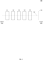
- FIG. 1 is a schematic diagram illustrating an exemplary lens system according to some embodiments of the present disclosure.
- the lens system 100 includes a first lens group G1, a second lens group G2, a third lens group G3, a fourth lens group G4, a fifth lens group G5, and an image plane 106 in sequence from an object side to an image side along an optical axis 102 of the lens system 100.
- the image plane 106 refers to a plane that is vertical to the optical axis 102 and includes an object's projected image generated based on the lens system 100.
- a lens group e.g., G1-G5 may include one or more lenses.
- At least one of G1, G2, G3, G4, and G5 may be adjustable along the optical axis 102 of the lens system 100 to change the magnification (i.e., adjust the focal length) of the lens system 100.
- G1, G3, and G5 may be fixed relative to the image plane 106 during the magnification change of the lens system 100.
- G2 and G4 are adjustable along the optical axis 102 of the lens system 100 to adjust the focal length of the lens system 100.
- G1, G3, and G5 may be referred to as first fixed lens group, second fixed lens group, and third fixed lens group, respectively.
- G2 may be referred to as zoom lens group and G4 may be referred to as focusing lens group.
- the lens system 100 may have different working states (e.g., having different focal lengths).
- the lens system 100 may be at a telephoto end when it is focused on an object at a maximum focal length of its zoom range.
- the lens system 100 may be at a wide-angle end when it is focused on an object at a minimum focal length of its zoom range.
- the focal lengths of the lens system 100 satisfy formulas (1)-(3) below: a ⁇ f 2 f w ⁇ f t 1 / 2 ⁇ b , c ⁇ f 3 f w ⁇ f t 1 / 2 ⁇ d , e ⁇ f 4 f w ⁇ f t 1 / 2 ⁇ f , wherein a , b, c, d, e , and f are constants, f 2 represents the focal length of G2, f 3 represents the focal length of G3, f 4 represents the focal length of G4, f w represents the focal length of the lens system 100 at a wide-angle end, and f t represents the focal length of the lens system 100 at a telephoto end.
- a, b, c, d, e, and f are set as specific values to ensure the size of the lens system 100 and/or the correction of aberrations, such as spherical aberration, coma aberration, astigmatism, field curvature, distortion, axial chromatic aberration, or lateral chromatic aberration.
- aberrations such as spherical aberration, coma aberration, astigmatism, field curvature, distortion, axial chromatic aberration, or lateral chromatic aberration.
- a is equal to -1.33
- b is equal to -1.03
- c is equal to 1.56
- d is equal to 1.86
- e is equal to 1.21
- f is equal to 1.51. Therefore, the focal lengths of the lens system lens 100 satisfy formulas (4)-(6) below: ⁇ 1.33 ⁇ f 2 f w ⁇ f t 1 2 ⁇ ⁇ 1.03 , 1.56 ⁇ f 3 f w ⁇ f t 1 2 ⁇ 1.86 , 1.21 ⁇ f 4 f w ⁇ f t 1 2 ⁇ 1.51 .
- refractive power of G3 may be too weak, leading to an increase of the size of G3 (e.g., the diameter of the maximum cross-section vertical to the optical axis 102 of at least one lens in G3).
- the refractive power of G3 may be too strong, making the aberrations of the lens system 100 produced at different focal lengths (e.g., the focal lengths varying from the wide-angle end to the telephoto end) difficult to be corrected.
- the refractive power also referred to as optical power refers to the degree to which an optical system (e.g., the lens system 100) converges or diverges light (also referred to as rays).
- the optical system may converge the incident light of the optical system. If the optical system has negative refractive power, the optical system may diverge the incident light of the optical system. The larger the absolute value of the refractive power is, the larger the degree to which the optical system may converge or diverge the incident light.
- the size of the image plane 106 of the lens system 100 may be relatively large, the maximum aperture corresponding to different focal lengths (e.g., the focal lengths varying from the wide-angle end to the telephoto end) is constant, and the size of the maximum aperture may be relatively large.
- the size of the image plane is 3.38667 cm (4/3 inch).
- the size of the maximum aperture may be F1.5.
- G1 has positive refractive power
- G2 has negative refractive power
- G3 has positive refractive power
- G4 has positive refractive power
- G5 has positive refractive power
- the lens system 100 may include at least one aspherical lens.
- the lenses in the lens system 100 may be spherical lenses, which brings the benefits of low cost, high stability, suitability for mass production.
- the lens system 100 may also include one or more aperture stops (not shown in FIG. 1 ).
- the aberrations e.g., spherical aberration, astigmatism, distortion
- the lens system 100 may also include one or more color filters (not shown in FIG. 1 ) configured to correct color deviation of light incident to the lens system 100.
- FIG. 2 is a schematic diagram illustrating an exemplary lens system according to some embodiments of the present disclosure.
- the lens system 100-1 in FIG. 2 may be an example of the lens system 100 in FIG. 1 .
- the lens system 100-1 may include a first lens group G1 having positive refractive power, a second lens group G2 having negative refractive power, an aperture stop 104, a third lens group G3 having positive refractive power, a fourth lens group G4 having positive refractive power, a fifth lens group G5 having positive refractive power, and one or more color filters 108 in sequence from an object side to an image side along an optical axis 102 of the lens system 100-1.
- G1, G3, and G5 may be fixed relative to the image plane 106 during the magnification change of the lens system 100-1, and G2 and G4 may be adjustable along the optical axis 102 of the lens system 100-1 to adjust the focal length of the lens system 100-1.
- the lens system 100-1 may limit a first adjusting line for adjusting G2 along the optical axis 102 and a second adjusting line for adjusting G4 along the optical axis 102.
- the lens system 100-1 When G2 is adjusted along the optical axis 102 to the object-side end of the first adjusting line and G4 is adjusted along the optical axis 102 to the object-side end of the second adjusting line, the lens system 100-1 may be at the wide-angle end. When G2 is adjusted along the optical axis 102 to the image-side end of the first adjusting line and G4 is adjusted along the optical axis 102 to the image-side end of the second adjusting line, the lens system 100-1 may be at the telephoto end. In some embodiments, the focal lengths of the lens system lens 100-1 may satisfy formulas (4)-(6).
- G1 may include a first meniscus lens L11 having negative refractive power, a biconvex lens L12 having positive refractive power, and a second meniscus lens L13 having positive refractive power in sequence from the object side to the image side along the optical axis 102 of the lens system 100-1.
- L11 and L13 may be with a convex surface toward the object side (e.g., a convex object-side surface) of the lens system 100-1.
- a meniscus lens is a lens having two spherically curved surfaces, one convex and the other concave.
- a meniscus lens having positive refractive power may be thicker in the middle than at the edges and serve as a converging lens.
- a meniscus lens having negative refractive power e.g., L11 in FIG. 2
- a meniscus lens having negative refractive power may be thicker at the edges than in the middle and serve as a diverging lens.
- two or more lens may be cemented together.
- the cementation of a lens having the positive refractive power (e.g., L12) and a lens having the negative refractive power (e.g., L11) may reduce aberrations of the lens system 100, such as spherical aberration, astigmatism, axial chromatic aberration, etc.
- L11 and L12 may be cemented together (e.g., as shown in FIG. 2 ) or not be cemented together.
- G2 may include a first lens L21 having negative refractive power, a biconcave lens L22 having negative refractive power, and a second lens L23 having positive refractive power in sequence from the object side to the image side along the optical axis 102 of the lens system 100-1.
- L21 may be with a concave surface toward the image side (also referred to as image-side surface) of the lens system 100.
- the surface of L21 toward the object side of the lens system 100 (e.g., the object-side surface of L21) may be a concave surface, a convex surface, or a plane surface.
- L21 may be a biconcave lens (e.g., as shown in FIG.
- L23 may be with a convex surface toward the object side (e.g., a convex object-side surface) of the lens system 100-1.
- the surface of L23 toward the image side (e.g., the image-side surface) of the lens system 100 may be a concave surface, a convex surface, or a plane surface.
- L23 may be a biconvex lens, a plano-convex lens with a convex object-side surface and a plane image-side surface, or a meniscus lens (e.g., as shown in FIG. 2 ) with a convex object-side surface and a concave image-side surface.
- G3 may include a first lens sub-group G31 having positive refractive power, a second lens sub-group G32, and a third lens sub-group G33 in sequence from the object side to the image side along the optical axis 102 of the lens system 100-1.
- a sub-group e.g., G31-G33 and G41
- G31-G33 and G41 may include one or more lenses.
- each of G32 and G33 may include a lens having negative refractive power and a lens having positive refractive power that are cemented together.
- G31 may include a first biconvex lens L31 having positive refractive power, a biconcave lens L32 having negative refractive power, and a second biconvex lens L33 having positive refractive power that are cemented together in sequence from the object side to the image side along the optical axis 102 of the lens system 100-1.
- G32 may include a biconcave lens L34 having negative refractive power and a biconvex lens L35 having positive refractive power that are cemented together in sequence from the object side to the image side along the optical axis 102 of the lens system 100-1.
- G33 may include a biconvex lens L35 having positive refractive power and a biconcave lens L36 having negative refractive power that are cemented together in sequence from the object side to the image side along the optical axis 102 of the lens system 100-1.
- G4 may include a biconvex lens L41 having positive refractive power and a fourth lens sub-group G41 in sequence from the object side to the image side along the optical axis 102 of the lens system 100-1.
- G41 may include a lens having negative refractive power and a lens having positive refractive power that are cemented together.
- G41 may include a biconcave lens L42 having negative refractive power and a biconvex lens L43 having positive refractive power that are cemented together in sequence from the object side to the image side along the optical axis 102 of the lens system 100-1.
- G5 may include a third meniscus lens L51 having negative refractive power and a fourth meniscus lens L52 having positive refractive power in sequence from the object side to the image side along the optical axis 102 of the lens system 100-1.
- L51 and L52 may be with a convex surface toward the object side (e.g., a convex object-side surface) of the lens system 100-1.
- L51 and L52 may be cemented together.
- exemplary optical parameters of G1, G2, the aperture stop 104, G3, G4, G5, and the one or more color filters 108 in the lens system 100-1 are illustrated in Table 1.
- Table 1 Optical parameters of optical elements in the lens system 100-1 Surface Number Radius of Curvature R (mm) Surface Distance T c (mm) Refractive Index N d Abbe Number V d 1 546.38 2.25 1.847 23.785 2 154.69 6.23 1.593 67.002 3 -289.84 0.2 4 68.48 6.7 1.593 68.624 5 243.27 1.95 (W)-51.66 (T tele ) 6 -382.99 1.2 1.755 52.329 7 33.82 6.85 8 -67.03 1.2 1.497 81.608 9 76 1.63 10 59.8 3.56 1.954 32.319 11 482.82 52.17 (W)-2.46 (T tele ) 12 (aperture stop) 55.75 8.46 1.593 68.624 13 -29
- Each lens in the lens system 100-1 may include two surfaces, an object-side surface and an image-side surface.
- each value in the column of "Surface Number” represents the serial number of each surface of the lenses in the lens system 100-1, wherein “1” in the column of "Surface Number” represents the serial number of the object-side surface of L11 and the serial number is sequentially increased toward the image side.
- the cemented surfaces may have a same surface number.
- "2" in the column of "Surface Number” in Table 1 represents the cemented surfaces of L11 and L12 (e.g., the image-side surface of L11 and the object-side surface of L12 in FIG. 2 ).
- Each value in the column of "Radius of Curvature R (mm)” represents the radius of curvature of a corresponding lens surface.
- Each value in the column of “Surface Distance Tc (mm)” represents the distance along the optical axis 102 between a corresponding lens surface and the next lens surface.
- “2.25" in the column of “Surface Distance Tc (mm)” represents the distance along the optical axis 102 between lens surface 1 (e.g., the object-side surface of L11) and lens surface 2 (e.g., the cemented surfaces of L11 and L12) is 2.25 mm.
- W in the present disclosure represents the wide-angle end of a lens system (e.g., the lens system 100, the lens system 100-1, the lens system 100-2), and “T tele” in the present disclosure represents the telephoto end of the lens system.
- Different focus lengths of the lens system 100-1 may correspond to different locations of G2 and G4 along the optical axis 102 and different distances between G2 (or G4) and the adjacent lens group.
- the distance between lens surface 5 e.g., the image-side surface of L13 in FIG. 2
- lens surface 6 e.g., the object-side surface of L21 in FIG.
- lens 2 is 1.95 mm (e.g., represented as “1.95 (W)” in the column of "Surface Distance Tc (mm)”) when the lens system 100-1 is at the wide-angle end.
- the distance between lens surface 5 and lens surface 6 is 51.66 mm (e.g., represented as "51.66 (T tele )" in the column of "Surface Distance Tc (mm)") when the lens system 100-1 is at the telephoto end.
- Each value in the column of "Refractive Index Nd” in Table 1 represents the refractive index of the medium between a corresponding lens surface and the next lens surface.
- Each value in the column of "Abbe Number Vd” in Table 1 represents the Abbe number of the medium between a corresponding lens surface and the next lens surface.
- the Abbe number may be a measure of a medium's dispersion (variation of refractive index versus wavelength), with high values indicating low dispersion.
- the refractive index and the Abbe number of a lens may depend on the material of the lens.
- the optical parameters of the optical elements in the lens system 100-1 may be important to correct the aberrations of the lens system 100-1.
- spherical aberration and coma aberration of the lens system 100-1 may be reduced by adjusting the refractive indexes (e.g., by changing the material of the optical elements) and/or the radiuses of curvature of the optical elements in the lens system 100-1.
- lateral chromatic aberration of the lens system 100-1 may be reduced by adjusting the surface distances of the optical elements in the lens system 100-1.
- the lens system 100-1 may have the optical performance below:
- the values of the radius of curvature, the surface distance, the refractive index, the Abbe number of each lens in the lens system 100-1 are not limited to the values shown in Table 1 and may take different values.
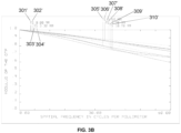
- FIGs. 3A and 3B are schematic diagrams of modulation transfer function (MTF) curve of the lens system 100-1 at a wide-angle end and a telephoto end, respectively, according to some embodiments of the present disclosure.
- MTF modulation transfer function
- a diagram of MTF curve of a lens system may assess the imaging quality of the lens system.
- one or more patterns each of which includes a plurality of stripes in black alternating with white may be captured using the lens system 100-1.
- the density of the black and white stripes may be represented by "spatial frequency" in line pairs per millimeter (lp/mm). Each line pair may include a black strip and the adjacent white stripe.
- the density of the black and white stripes in a pattern may be constant or varying.
- the difference between the captured pattern and the image of the captured pattern may be measured and quantified by the MTF value. The larger the MTF value is, the less the difference between the captured pattern and the image of the captured pattern may be.
- the MTF may be the modulus of the optical transfer function (OTF).
- the pattern may be placed in a circle (e.g., the field of view of the lens system 100-1) along the radial direction (e.g., the black and white stripes are parallel to a radial direction of the circle, or the black and white stripes radiate outwards from the center of the circle) and/or the tangential direction (e.g., the black and white stripes are vertical to a radial direction of the circle, or the black and white stripes are concentric circles of the circle).
- the MTF values corresponding to different spatial frequencies at a location in the circle may be determined.
- the MTF curves may be generated based on the MTF values.
- the MTF curve generated based on the pattern along the radial direction may be referred to as a sagittal MTF curve.
- the MTF curve generated based on the pattern along the tangential direction may be referred to as a tangential MTF curve.
- a same location in the circle may correspond to two MTF curves, i.e., the sagittal MTF curve and the tangential MTF curve.
- the better the imaging quality of the lens system in the entire zoom focal length may be and the better the lens system may correct the aberrations, such as spherical aberration, coma aberration, astigmatism, field curvature, distortion, axial chromatic aberration, or lateral chromatic aberration.
- aberrations such as spherical aberration, coma aberration, astigmatism, field curvature, distortion, axial chromatic aberration, or lateral chromatic aberration.
- the MTF curves are the MTF curves of visible light of which the wavelength is 0.4350 ⁇ m-0.65 ⁇ m.
- the horizontal axis represents spatial frequency in circles per millimeter (in lp/mm), and the vertical axis represents the modulus of the OTF (e.g., the MTF value).
- "T" represents the tangential MTF curve corresponding to a location and "S” represents the sagittal MTF curve corresponding to a location.
- curves 301, 303, 305, 307, and 309 may be the tangential MTF curves generated, at the wide-angle end of the lens system 100-1, based on locations whose distances away from the imaging center of the field of view of the lens system 100-1 are 0.00 mm, 3.3 mm, 5.5 mm, 7.7 mm, 10.78 mm, respectively.
- Curves 302, 304, 306, 308, and 310 may be the sagittal MTF curves generated, at the wide-angle end of the lens system 100-1, based on locations whose distances away from the imaging center of the field of view of the lens system 100-1 are 0.00 mm, 3.3 mm, 5.5 mm, 7.7 mm, 10.78 mm, respectively. As shown in FIG.
- curves 301', 303', 305', 307', and 309' may be the tangential MTF curves generated, at the telephoto end of the lens system 100-1, based on locations whose distances away from the imaging center of the field of view of the lens system 100-1 are 0.00 mm, 3.3 mm, 5.5 mm, 7.7 mm, 10.78 mm, respectively.
- Curves 302', 304', 306', 308', and 310' may be the sagittal MTF curves generated, at the telephoto end of the lens system 100-1, based on locations whose distances away from the imaging center of the field of view of the lens system 100-1 are 0.00 mm, 3.3 mm, 5.5 mm, 7.7 mm, 10.78 mm, respectively.
- the MTF curves at the wide-angle end and at the telephoto end are relatively similar, the averages of the MTF values of the full field of view (e.g., when the spatial frequency is equal to 60 lp/mm as shown in FIG. 3A and/or FIG.
- the lens system 100-1 may achieve relatively high resolution and allow obtaining images with high quality.
- the lens system 100-1 may be applicable to a camera with 12 megapixels and a 4/3-inch image plane.
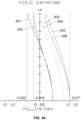
- FIGs. 4A and 4B are schematic diagrams of field curvature of the lens system 100-1 at a wide-angle end and a telephoto end, respectively, according to some embodiments of the present disclosure.
- Field curvature may be an optical aberration in which a planar object is projected to a curved (nonplanar) image and cannot be brought properly into focus on a flat image plane. This happens due to the curved nature of optical elements (e.g., the lenses) in the lens system, which project the image in a curved manner, rather than flat.
- a plane including the optical axis of the lens system and a point out of the optical axis may be referred to as a tangential plane.
- Incident rays on the tangential plane may be referred to as tangential rays.
- a plane that includes the optical axis of the lens system and is vertical to the tangential plane may be referred to as a sagittal plane.
- Incident rays on the sagittal plane may be referred to as sagittal rays.
- the diagram of field curvature may indicate the aberration of the tangential rays (e.g., tangential field curvature), the aberration of the sagittal rays (e.g., sagittal field curvature), and the correction ability of field curvature of the lens system.
- curves 401, 403, and 405 are the field curvature curves of the tangential rays (also referred to as the tangential field curvature curves) with the wavelength of 486 nm, 587 nm, and 656 nm, respectively, at the wide-angle end of the lens system 100-1.
- Curves 402, 404, and 406 are the field curvature curves of the sagittal rays (also referred to as the sagittal field curvature curves) with the wavelength of 486 nm, 587 nm, and 656 nm, respectively, at the wide-angle end of the lens system 100-1.
- the sagittal field curvature occurring in the lens system 100-1 at the wide-angle end is limited to a range of -0.032 mm-0.077 mm
- the tangential field curvature occurring in the lens system 100-1 at the wide-angle end is limited to a range of -0.016 mm-0.077 mm.
- curves 401', 403', and 405' are the field curvature curves of the tangential rays (also referred to as the tangential field curvature curves) with the wavelength of 486 nm, 587 nm, and 656 nm, respectively, at the telephoto end of the lens system 100-1.
- Curves 402', 404', and 406' are the field curvature curves of the sagittal rays (also referred to as the sagittal field curvature curves) with the wavelength of 486 nm, 587 nm, and 656 nm, respectively, at the telephoto end of the lens system 100-1. As shown in FIG.
- the sagittal field curvature occurring in the lens system 100-1 at the telephoto end is limited to a range of -0.006 mm-0.05 mm
- the tangential field curvature occurring in the lens system 100-1 at the telephoto end is limited to a range of -0.015 mm-0.05 mm.
- the field curvature of the lens system 100-1 may be limited to a relatively small range, which indicates that the periphery of the image plane of the lens system 100-1 may have relatively high resolution.
- FIGs. 5A and 5B are schematic diagrams illustrating axial chromatic aberration of the lens system 100-1 at a wide-angle end and a telephoto end, respectively, according to some embodiments of the present disclosure.
- the rays with different wavelengths may have different image points because of axial chromatic aberration, which makes an image of the object point include colored spots and/or halos. This happens due to different focal lengths of the lens system corresponding to rays with different wavelengths.
- the horizontal axis relates to the incident height of rays from an object point with respect to the lens system 100-1
- the vertical axis relates to the distance between the actual image point of the object point and the ideal image point of the object point.
- curves 501-503 are the aberration curves of the rays with the wavelengths of 486 nm, 588 nm, and 656 nm, respectively, at the wide-angle end of the lens system 100-1.
- the axial chromatic aberration occurring in the lens system 100-1 at the wide-angle end is limited to a range of -0.064 mm-0.078 mm.
- curves 501'-503' are the aberration curves of the rays with the wavelengths of 486 nm, 588 nm, and 656 nm, respectively, at the telephoto end of the lens system 100-1.
- the pupil radius of the lens system 100-1 used to capture an object or an object point to generate curves 501-503 and 501'-503' is 7.5523 mm.
- the axial chromatic aberration occurring in the lens system 100-1 at the telephoto end is limited to a range of -0.1 mm-0.05 mm.
- the axial chromatic aberration of the lens system 100-1 may be limited to a relatively small range, which increases the definition of the center and the periphery of an image generated using the lens system 100-1.
- FIGs. 6A and 6B are schematic diagrams illustrating lateral chromatic aberration of the lens system 100-1 at a wide-angle end and a telephoto end, respectively, according to some embodiments of the present disclosure.
- Lateral chromatic aberration may be an optical aberration in which an image of an object has colored edges and poor definition. This is caused by the fact that rays of different wavelengths are not equally refracted by the lens system, so that rays of different wavelengths from a same point (e.g., a point out of the optical axis of the lens system) corresponds to different image heights.
- the horizontal axis relates to the incident height of rays from an object point to the lens system 100-1
- the vertical axis relates to the distance between the actual image point of the object point and the ideal image point of the object point.
- the maximum field of the lens system 100-1 used to capture an object or an object point to generate curves 601-603 and 601'-603' is 10.7800 mm.
- curves 601-603 are the aberration curves of the rays with the wavelengths of 486 nm, 588 nm, and 656 nm, respectively, at the wide-angle end of the lens system 100-1.
- Curves 601 and 603 are generated by determining curve 602 as a reference curve.
- curve 602 As shown in FIG. 6A , the lateral chromatic aberration occurring in the lens system 100-1 at the wide-angle end is limited to a range of -0.0023 mm-0.0067 mm. As shown in FIG.
- curves 601'-603' are the aberration curves of the rays with the wavelengths of 486 nm, 588 nm, and 656 nm, respectively, at the telephoto end of the lens system 100-1.
- Curves 601' and 603' are generated by determining curve 602' as a reference curve. In this case, at the telephoto end, it is assumed that the actual image point of the object point and the ideal image point of the object point corresponding to the rays with the wavelengths of 588 nm is overlapped at any incident height. As shown in FIG.
- the lateral chromatic aberration occurring in the lens system 100-1 at the telephoto end is limited to a range of -0.0013 mm-0.0003 mm.
- the lateral chromatic aberration of the lens system 100-1 may be limited to a relatively small range, which increases the definition of the center and the periphery of an image generated using the lens system 100-1.
- the lens system 100-1 may well correct the aberrations, such as spherical aberration, coma aberration, astigmatism, field curvature, distortion, axial chromatic aberration, or lateral chromatic aberration.
- the lens system 100-1 may have a larger aperture (e.g., F1.5) and higher resolution (e.g., applicable to a camera with 12 megapixels).
- the lens system 100-1 may be applicable to capturing ultra high-definition (HD) images and/or video in all weather conditions in the field of, for example, security monitoring.
- HD ultra high-definition
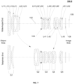
- FIG. 7 is a schematic diagram illustrating an exemplary lens system according to some embodiments of the present disclosure.
- the lens system 100-2 in FIG. 7 may be an example of the lens system 100 in FIG. 1 .
- the lens system 100-2 may include a first lens group G1 having positive refractive power, a second lens group G2 having negative refractive power, an aperture stop 104, a third lens group G3 having positive refractive power, a fourth lens group G4 having positive refractive power, a fifth lens group G5 having positive refractive power, and one or more color filters 108 in sequence from an object side to an image side along an optical axis 102 of the lens system 100-2.
- G1, G3, and G5 may be fixed relative to the image plane 106 during the magnification change of the lens system 100-2.
- G2 and G4 may be adjustable along the optical axis 102 of the lens system 100-2 to adjust the focal length of the lens system 100-2.
- the lens system 100-2 may limit a third adjusting line for adjusting G2 along the optical axis 102 and a fourth adjusting line for adjusting G4 along the optical axis 102.
- the lens system 100-2 may be at the wide-angle end.
- the lens system 100-2 may be at the telephoto end.
- the lens system lens 100-2 may satisfy formulas (4)-(6).
- G3 may include a first lens sub-group G31 having positive refractive power, a second lens sub-group G32, and a third lens sub-group G33 in sequence from the object side to the image side along the optical axis 102 of the lens system 100-2.
- G31 may include a biconvex lens L31' having positive refractive power and a meniscus lens L32' having positive refractive power in sequence from the object side to the image side along the optical axis 102 of the lens system 100-2.
- the object-side surface of L32' may be a convex surface (e.g., as shown in FIG. 7 ) or a concave surface.
- G32 may include a biconcave lens L33' having negative refractive power and a biconvex lens L34' having positive refractive power that are cemented together in sequence from the object side to the image side along the optical axis 102 of the lens system 100-2.
- G33 may include a meniscus lens L35' having positive refractive power and a biconcave lens L36' having negative refractive power in sequence from the object side to the image side along the optical axis 102 of the lens system 100-2.
- the object-side surface of L35' may be a convex surface or a concave surface (e.g., as shown in FIG. 7 ). If the object-side surface of L35' is the concave surface, L35' and L36' may be cemented together.
- the structure of G1, G2, G4, and G5 may be similar to the lens system 100-1 in FIG. 2 and is not described in FIG. 7 .
- the lens systems may be used in an imaging device, such as a digital camera, a web camera, a video gaming console equipped with a web camera, a video camera, a motion picture camera, a broadcasting camera, or a closed circuit television (CCTV) camera.
- an image sensor such as a charge-coupled device (CCD) or a complementary metal oxide semiconductor (CMOS)
- CCD charge-coupled device
- CMOS complementary metal oxide semiconductor
- An analog-digital converter (ADC) in the imaging device may transform the electronic signals to digital signals.
- Image processing circuits in the imaging device may process the digital signals to generate an image of the object.
- a storage medium in the imaging device may record the generated image. With the imaging device, a still image, a moving image, or a video may be captured.
- the imaging device that is provided with the lens system in the present disclosure may achieve a high image stabilization effect and allow obtaining high quality images.
Landscapes
- Physics & Mathematics (AREA)
- General Physics & Mathematics (AREA)
- Optics & Photonics (AREA)
- Lenses (AREA)
Claims (15)
- Linsensystem, das eine erste Linsengruppe, eine zweite Linsengruppe, eine dritte Linsengruppe, eine vierte Linsengruppe und eine fünfte Linsengruppe in Folge von einer Objektseite zu einer Bildseite entlang einer optischen Achse des Linsensystems umfasst, wobei:die erste Linsengruppe eine positive Brechkraft aufweist, die zweite Linsengruppe eine negative Brechkraft aufweist, die dritte Linsengruppe eine positive Brechkraft aufweist, die vierte Linsengruppe eine positive Brechkraft aufweist und die fünfte Linsengruppe eine positive Brechkraft aufweist;die zweiten Linsengruppen und die vierte Linsengruppe entlang der optischen Achse des Linsensystems anpassbar sind, um eine Brennweite des Linsensystems anzupassen; unddadurch gekennzeichnet, dass das Linsensystem erfüllt
 wobei das Linsensystem, um eine gewünschte Bildqualität zu realisieren, eine Bildebene mit einer Größe von 3,38667 cm (4/3 Zoll) und eine konstante maximale Blendenöffnung aufweist, die den Brennweiten von einem Weitwinkelende zu einem Teleobjektivende entspricht;wobei f 2 eine Brennweite der zweiten Linsengruppe darstellt, f 3 eine Brennweite der dritten Linsengruppe darstellt, f 4 eine Brennweite der vierten Linsengruppe darstellt, fw eine Brennweite des Linsensystems am Weitwinkelende darstellt und ft eine Brennweite des Linsensystems am Teleobjektivende darstellt.
 - Linsensystem nach Anspruch 1, wobei in der ersten Linsengruppe eine erste Meniskuslinse, die eine negative Brechkraft aufweist, eine erste bikonvexe Linse, die eine positive Brechkraft aufweist, und eine zweite Meniskuslinse, die eine positive Brechkraft aufweist, in Folge von der Objektseite zu der Bildseite entlang der optischen Achse des Linsensystems angeordnet sind, wobei jede von der ersten Meniskuslinse und der zweiten Meniskuslinse mit einer konvexen Oberfläche in Richtung zur Objektseite des Linsensystems steht.
- Linsensystem nach einem der Ansprüche 1 bis 2, wobei in der zweiten Linsengruppe eine erste Linse, die eine negative Brechkraft aufweist, eine erste bikonkave Linse, die eine negative Brechkraft aufweist, und eine zweite Linse, die eine positive Brechkraft aufweist, in Folge von der Objektseite zu der Bildseite entlang der optischen Achse des Linsensystems angeordnet sind, wobei die erste Linse mit einer konkaven Oberfläche in Richtung zur Bildseite des Linsensystems steht und die zweite Linse mit einer konvexen Oberfläche in Richtung zur Objektseite des Linsensystems steht.
- Linsensystem nach einem der Ansprüche 1 bis 3, wobei in der dritten Linsengruppe eine erste Linsenuntergruppe, die eine positive Brechkraft aufweist, eine zweite Linsenuntergruppe und eine dritte Linsenuntergruppe in Folge von der Objektseite zu der Bildseite entlang der optischen Achse des Linsensystems angeordnet sind.
- Linsensystem nach Anspruch 4, wobei:in der ersten Linsenuntergruppe eine zweite bikonvexe Linse, die eine positive Brechkraft aufweist, eine zweite bikonkave Linse, die eine negative Brechkraft aufweist, und eine dritte bikonvexe Linse, die eine positive Brechkraft aufweist, in Folge von der Objektseite zu der Bildseite entlang der optischen Achse des Linsensystems miteinander verkittet sind;in der zweiten Linsenuntergruppe eine dritte bikonkave Linse, die eine negative Brechkraft aufweist, und eine vierte bikonvexe Linse, die eine positive Brechkraft aufweist, in Folge von der Objektseite zu der Bildseite entlang der optischen Achse des Linsensystems miteinander verkittet sind; undin der dritten Linsenuntergruppe eine fünfte bikonvexe Linse, die eine positive Brechkraft aufweist, und eine vierte bikonkave Linse, die eine negative Brechkraft aufweist, in Folge von der Objektseite zu der Bildseite entlang der optischen Achse des Linsensystems miteinander verkittet sind.
- Linsensystem nach Anspruch 4, wobei:in der ersten Linsenuntergruppe eine sechste bikonvexe Linse, die eine positive Brechkraft aufweist, und eine dritte Meniskuslinse, die eine positive Brechkraft aufweist, in Folge von der Objektseite zu der Bildseite entlang der optischen Achse des Linsensystems angeordnet sind;in der zweiten Linsenuntergruppe eine fünfte bikonkave Linse, die eine negative Brechkraft aufweist, und eine siebte bikonvexe Linse, die eine positive Brechkraft aufweist, in Folge von der Objektseite zu der Bildseite entlang der optischen Achse des Linsensystems miteinander verkittet sind; undin der dritten Linsenuntergruppe eine sechste Meniskuslinse, die eine positive Brechkraft aufweist, und eine sechste bikonkave Linse, die eine negative Brechkraft aufweist, in Folge von der Objektseite zu der Bildseite entlang der optischen Achse des Linsensystems miteinander verkittet sind.
- Linsensystem nach Anspruch 6, wobei eine objektseitige Oberfläche der dritten Meniskuslinse in der ersten Linsenuntergruppe eine konvexe Oberfläche ist.
- Linsensystem nach Anspruch 6, wobei eine objektseitige Oberfläche der dritten Meniskuslinse in der ersten Linsenuntergruppe eine konkave Oberfläche ist und die sechste bikonvexe Linse und die dritte Meniskuslinse in der ersten Linsenuntergruppe miteinander verkittet sind.
- Linsensystem nach einem der Ansprüche 1 bis 8, wobei in der vierten Linsengruppe eine neunte bikonvexe Linse, die eine positive Brechkraft aufweist, und eine vierte Linsenuntergruppe in Folge von der Objektseite zu der Bildseite entlang der optischen Achse des Linsensystems angeordnet sind.
- Linsensystem nach Anspruch 9, wobei in der vierten Linsenuntergruppe eine siebte bikonkave Linse, die eine negative Brechkraft aufweist, und eine zehnte bikonvexe Linse, die eine positive Brechkraft aufweist, in Folge von der Objektseite zu der Bildseite entlang der optischen Achse des Linsensystems miteinander verkittet sind.
- Linsensystem nach einem der Ansprüche 1 bis 10, wobei in der fünften Linsengruppe eine vierte Meniskuslinse, die eine negative Brechkraft aufweist, und eine fünfte Meniskuslinse, die eine positive Brechkraft aufweist, in Folge von der Objektseite zu der Bildseite entlang der optischen Achse des Linsensystems angeordnet sind, wobei die vierte Meniskuslinse und die fünfte Meniskuslinse mit einer konvexen Oberfläche in Richtung zur Objektseite des Linsensystems stehen.
- Linsensystem nach einem der Ansprüche 1 bis 11, wobei Linsen in dem Linsensystem sphärische Linsen sind.
- Linsensystem nach einem der Ansprüche 1 bis 12, wobei das Linsensystem mindestens eine asphärische Linse beinhaltet.
- Linsensystem nach einem der Ansprüche 1 bis 13, wobei
das Linsensystem weiter einen Blendenöffnungsstopp zwischen der zweiten Linsengruppe und der dritten Linsengruppe umfasst. - Bildgebungsvorrichtung, die das Linsensystem nach Anspruch 1 umfasst.
Applications Claiming Priority (2)
| Application Number | Priority Date | Filing Date | Title |
|---|---|---|---|
| CN201710786947.3A CN107589534B (zh) | 2017-09-04 | 2017-09-04 | 一种透镜系统及镜头 |
| PCT/CN2018/103872 WO2019042452A1 (en) | 2017-09-04 | 2018-09-04 | IMAGING SYSTEM AND IMAGING DEVICE |
Publications (3)
| Publication Number | Publication Date |
|---|---|
| EP3662317A1 EP3662317A1 (de) | 2020-06-10 |
| EP3662317A4 EP3662317A4 (de) | 2020-10-28 |
| EP3662317B1 true EP3662317B1 (de) | 2025-02-19 |
Family
ID=61050862
Family Applications (1)
| Application Number | Title | Priority Date | Filing Date |
|---|---|---|---|
| EP18851395.6A Active EP3662317B1 (de) | 2017-09-04 | 2018-09-04 | Linsensystem und bildgebungsvorrichtung |
Country Status (4)
| Country | Link |
|---|---|
| US (1) | US11204488B2 (de) |
| EP (1) | EP3662317B1 (de) |
| CN (1) | CN107589534B (de) |
| WO (1) | WO2019042452A1 (de) |
Families Citing this family (8)
| Publication number | Priority date | Publication date | Assignee | Title |
|---|---|---|---|---|
| CN107589534B (zh) * | 2017-09-04 | 2019-09-17 | 浙江大华技术股份有限公司 | 一种透镜系统及镜头 |
| CN109445079B (zh) * | 2018-12-17 | 2024-04-09 | 东莞市宇瞳光学科技股份有限公司 | 一种变焦镜头及摄像机 |
| CN111435191B (zh) * | 2019-01-14 | 2022-10-14 | 杭州海康威视数字技术股份有限公司 | 一种变焦镜头及摄像机及监控设备 |
| CN110196484B (zh) * | 2019-05-30 | 2020-06-23 | 浙江大华技术股份有限公司 | 一种镜头 |
| CN110955035B (zh) * | 2019-12-23 | 2025-08-08 | 舜宇光学(中山)有限公司 | 变焦镜头 |
| EP3978964A1 (de) * | 2020-10-01 | 2022-04-06 | ASML Netherlands B.V. | Achromatische optische relaisanordnung |
| CN113296252B (zh) * | 2021-05-24 | 2022-10-28 | 江西凤凰光学科技有限公司 | 一种变焦镜头 |
| CN114089522B (zh) * | 2021-12-10 | 2025-03-18 | 舜宇光学(中山)有限公司 | 变焦镜头 |
Family Cites Families (24)
| Publication number | Priority date | Publication date | Assignee | Title |
|---|---|---|---|---|
| JP2543780B2 (ja) * | 1990-07-23 | 1996-10-16 | コニカ株式会社 | ズ―ムレンズ |
| JP3072815B2 (ja) * | 1993-10-08 | 2000-08-07 | キヤノン株式会社 | 変倍光学系 |
| JP3528947B2 (ja) | 1995-06-08 | 2004-05-24 | 株式会社ニコン | 近接撮影可能なズームレンズ |
| KR970002389A (ko) * | 1995-06-14 | 1997-01-24 | 김광호 | 줌(zoom)렌즈 광학계 |
| JP3601733B2 (ja) * | 1995-09-26 | 2004-12-15 | フジノン株式会社 | 高倍率ズームレンズ |
| JP4221670B2 (ja) | 2004-09-30 | 2009-02-12 | ソニー株式会社 | ズームレンズ及び撮像装置 |
| JP4244033B2 (ja) | 2004-10-14 | 2009-03-25 | ソニー株式会社 | ズームレンズ及び撮像装置 |
| JP2007322804A (ja) * | 2006-06-01 | 2007-12-13 | Sony Corp | ズームレンズ及び撮像装置 |
| JP4864600B2 (ja) * | 2006-08-11 | 2012-02-01 | 富士フイルム株式会社 | 投写型ズームレンズおよび投写型表示装置 |
| JP5126492B2 (ja) | 2007-10-01 | 2013-01-23 | 株式会社ニコン | ズームレンズ及びこのズームレンズを備えた光学機器 |
| JP5200527B2 (ja) | 2007-12-26 | 2013-06-05 | ソニー株式会社 | ズームレンズ及び撮像装置 |
| JP5846792B2 (ja) * | 2011-07-22 | 2016-01-20 | オリンパス株式会社 | ズームレンズ及びそれを用いた撮像装置 |
| CN103487913A (zh) | 2012-06-11 | 2014-01-01 | 苏州莱能士光电科技有限公司 | 超大像面日夜两用型高分辨率变焦镜头 |
| WO2014013648A1 (ja) * | 2012-07-17 | 2014-01-23 | パナソニック株式会社 | ズームレンズ系、撮像装置及びカメラ |
| JP5928426B2 (ja) * | 2013-09-25 | 2016-06-01 | コニカミノルタ株式会社 | 変倍光学系,撮像光学装置及びデジタル機器 |
| CN110058391B (zh) * | 2014-04-21 | 2021-11-23 | 株式会社尼康 | 变倍光学系统以及光学设备 |
| WO2015163368A1 (ja) | 2014-04-25 | 2015-10-29 | 株式会社ニコン | 変倍光学系、光学装置、変倍光学系の製造方法 |
| CN104049347B (zh) | 2014-06-20 | 2016-06-15 | 福建福光股份有限公司 | 紧凑型超大像面连续变焦镜头 |
| CN111880295B (zh) * | 2014-08-29 | 2022-12-09 | 株式会社尼康 | 变倍光学系统及光学设备 |
| JP6660757B2 (ja) * | 2016-02-12 | 2020-03-11 | 株式会社タムロン | ズームレンズおよび撮像装置 |
| CN205880341U (zh) * | 2016-07-19 | 2017-01-11 | 嘉兴中润光学科技有限公司 | 一种变焦镜头 |
| CN106125273B (zh) * | 2016-07-19 | 2018-10-16 | 嘉兴中润光学科技有限公司 | 一种变焦镜头 |
| JP6925190B2 (ja) * | 2017-07-12 | 2021-08-25 | 株式会社タムロン | ズームレンズ及び撮像装置 |
| CN107589534B (zh) * | 2017-09-04 | 2019-09-17 | 浙江大华技术股份有限公司 | 一种透镜系统及镜头 |
-
2017
- 2017-09-04 CN CN201710786947.3A patent/CN107589534B/zh active Active
-
2018
- 2018-09-04 EP EP18851395.6A patent/EP3662317B1/de active Active
- 2018-09-04 WO PCT/CN2018/103872 patent/WO2019042452A1/en not_active Ceased
-
2020
- 2020-03-04 US US16/808,575 patent/US11204488B2/en active Active
Also Published As
| Publication number | Publication date |
|---|---|
| EP3662317A1 (de) | 2020-06-10 |
| CN107589534A (zh) | 2018-01-16 |
| US20200201006A1 (en) | 2020-06-25 |
| US11204488B2 (en) | 2021-12-21 |
| CN107589534B (zh) | 2019-09-17 |
| WO2019042452A1 (en) | 2019-03-07 |
| EP3662317A4 (de) | 2020-10-28 |
Similar Documents
| Publication | Publication Date | Title |
|---|---|---|
| EP3662317B1 (de) | Linsensystem und bildgebungsvorrichtung | |
| US11320631B2 (en) | Lens system and imaging device | |
| US10359606B2 (en) | Optical image capturing system | |
| US10018807B2 (en) | Optical image capturing system | |
| US9851536B2 (en) | Optical image capturing system | |
| US9835831B2 (en) | Optical image capturing system | |
| KR102083931B1 (ko) | 광각 렌즈계 | |
| US9958648B2 (en) | Optical image capturing system | |
| US9869845B2 (en) | Optical image capturing system | |
| EP2637055B1 (de) | Zoomobjektiv und Fotografiervorrichtung damit | |
| US10254512B2 (en) | Optical image capturing system | |
| US20170090157A1 (en) | Optical image capturing system | |
| US9835829B2 (en) | Optical image capturing system | |
| US10288844B2 (en) | Optical image capturing system | |
| US20170139186A1 (en) | Optical image capturing system | |
| KR101527990B1 (ko) | 맞춤형 피사계 심도 광학계 및 콤팩트 패스트 렌즈 아키텍처 | |
| US20180231748A1 (en) | Optical image capturing system | |
| US20160356991A1 (en) | Optical image capturing system | |
| US9739980B2 (en) | Optical image capturing system | |
| US20180188491A1 (en) | Optical image capturing system | |
| US10139593B2 (en) | Optical image capturing system | |
| US20210231914A1 (en) | Optical image capturing system | |
| EP3249438A1 (de) | Zoomobjektivsystem | |
| US11719917B2 (en) | Optical image capturing system | |
| KR102066941B1 (ko) | 줌 렌즈계 |
Legal Events
| Date | Code | Title | Description |
|---|---|---|---|
| STAA | Information on the status of an ep patent application or granted ep patent |
Free format text: STATUS: THE INTERNATIONAL PUBLICATION HAS BEEN MADE |
|
| PUAI | Public reference made under article 153(3) epc to a published international application that has entered the european phase |
Free format text: ORIGINAL CODE: 0009012 |
|
| STAA | Information on the status of an ep patent application or granted ep patent |
Free format text: STATUS: REQUEST FOR EXAMINATION WAS MADE |
|
| 17P | Request for examination filed |
Effective date: 20200304 |
|
| AK | Designated contracting states |
Kind code of ref document: A1 Designated state(s): AL AT BE BG CH CY CZ DE DK EE ES FI FR GB GR HR HU IE IS IT LI LT LU LV MC MK MT NL NO PL PT RO RS SE SI SK SM TR |
|
| AX | Request for extension of the european patent |
Extension state: BA ME |
|
| RIC1 | Information provided on ipc code assigned before grant |
Ipc: G02B 15/14 20060101AFI20200630BHEP Ipc: G02B 15/15 20060101ALI20200630BHEP |
|
| REG | Reference to a national code |
Ref country code: DE Ref legal event code: R079 Free format text: PREVIOUS MAIN CLASS: G02B0015173000 Ipc: G02B0015140000 |
|
| A4 | Supplementary search report drawn up and despatched |
Effective date: 20200925 |
|
| RIC1 | Information provided on ipc code assigned before grant |
Ipc: G02B 15/14 20060101AFI20200921BHEP Ipc: G02B 15/15 20060101ALI20200921BHEP |
|
| DAV | Request for validation of the european patent (deleted) | ||
| DAX | Request for extension of the european patent (deleted) | ||
| STAA | Information on the status of an ep patent application or granted ep patent |
Free format text: STATUS: EXAMINATION IS IN PROGRESS |
|
| 17Q | First examination report despatched |
Effective date: 20220726 |
|
| GRAP | Despatch of communication of intention to grant a patent |
Free format text: ORIGINAL CODE: EPIDOSNIGR1 |
|
| STAA | Information on the status of an ep patent application or granted ep patent |
Free format text: STATUS: GRANT OF PATENT IS INTENDED |
|
| INTG | Intention to grant announced |
Effective date: 20241210 |
|
| GRAS | Grant fee paid |
Free format text: ORIGINAL CODE: EPIDOSNIGR3 |
|
| GRAA | (expected) grant |
Free format text: ORIGINAL CODE: 0009210 |
|
| STAA | Information on the status of an ep patent application or granted ep patent |
Free format text: STATUS: THE PATENT HAS BEEN GRANTED |
|
| AK | Designated contracting states |
Kind code of ref document: B1 Designated state(s): AL AT BE BG CH CY CZ DE DK EE ES FI FR GB GR HR HU IE IS IT LI LT LU LV MC MK MT NL NO PL PT RO RS SE SI SK SM TR |
|
| REG | Reference to a national code |
Ref country code: GB Ref legal event code: FG4D |
|
| REG | Reference to a national code |
Ref country code: CH Ref legal event code: EP |
|
| REG | Reference to a national code |
Ref country code: DE Ref legal event code: R096 Ref document number: 602018079412 Country of ref document: DE |
|
| REG | Reference to a national code |
Ref country code: IE Ref legal event code: FG4D |
|
| REG | Reference to a national code |
Ref country code: NL Ref legal event code: MP Effective date: 20250219 |
|
| PG25 | Lapsed in a contracting state [announced via postgrant information from national office to epo] |
Ref country code: RS Free format text: LAPSE BECAUSE OF FAILURE TO SUBMIT A TRANSLATION OF THE DESCRIPTION OR TO PAY THE FEE WITHIN THE PRESCRIBED TIME-LIMIT Effective date: 20250519 |
|
| PG25 | Lapsed in a contracting state [announced via postgrant information from national office to epo] |
Ref country code: FI Free format text: LAPSE BECAUSE OF FAILURE TO SUBMIT A TRANSLATION OF THE DESCRIPTION OR TO PAY THE FEE WITHIN THE PRESCRIBED TIME-LIMIT Effective date: 20250219 |
|
| PG25 | Lapsed in a contracting state [announced via postgrant information from national office to epo] |
Ref country code: PL Free format text: LAPSE BECAUSE OF FAILURE TO SUBMIT A TRANSLATION OF THE DESCRIPTION OR TO PAY THE FEE WITHIN THE PRESCRIBED TIME-LIMIT Effective date: 20250219 |
|
| PG25 | Lapsed in a contracting state [announced via postgrant information from national office to epo] |
Ref country code: ES Free format text: LAPSE BECAUSE OF FAILURE TO SUBMIT A TRANSLATION OF THE DESCRIPTION OR TO PAY THE FEE WITHIN THE PRESCRIBED TIME-LIMIT Effective date: 20250219 |
|
| REG | Reference to a national code |
Ref country code: LT Ref legal event code: MG9D |
|
| PG25 | Lapsed in a contracting state [announced via postgrant information from national office to epo] |
Ref country code: NO Free format text: LAPSE BECAUSE OF FAILURE TO SUBMIT A TRANSLATION OF THE DESCRIPTION OR TO PAY THE FEE WITHIN THE PRESCRIBED TIME-LIMIT Effective date: 20250519 Ref country code: IS Free format text: LAPSE BECAUSE OF FAILURE TO SUBMIT A TRANSLATION OF THE DESCRIPTION OR TO PAY THE FEE WITHIN THE PRESCRIBED TIME-LIMIT Effective date: 20250619 |
|
| PG25 | Lapsed in a contracting state [announced via postgrant information from national office to epo] |
Ref country code: NL Free format text: LAPSE BECAUSE OF FAILURE TO SUBMIT A TRANSLATION OF THE DESCRIPTION OR TO PAY THE FEE WITHIN THE PRESCRIBED TIME-LIMIT Effective date: 20250219 |
|
| PG25 | Lapsed in a contracting state [announced via postgrant information from national office to epo] |
Ref country code: HR Free format text: LAPSE BECAUSE OF FAILURE TO SUBMIT A TRANSLATION OF THE DESCRIPTION OR TO PAY THE FEE WITHIN THE PRESCRIBED TIME-LIMIT Effective date: 20250219 |
|
| PG25 | Lapsed in a contracting state [announced via postgrant information from national office to epo] |
Ref country code: PT Free format text: LAPSE BECAUSE OF FAILURE TO SUBMIT A TRANSLATION OF THE DESCRIPTION OR TO PAY THE FEE WITHIN THE PRESCRIBED TIME-LIMIT Effective date: 20250620 Ref country code: LV Free format text: LAPSE BECAUSE OF FAILURE TO SUBMIT A TRANSLATION OF THE DESCRIPTION OR TO PAY THE FEE WITHIN THE PRESCRIBED TIME-LIMIT Effective date: 20250219 |
|
| PG25 | Lapsed in a contracting state [announced via postgrant information from national office to epo] |
Ref country code: BG Free format text: LAPSE BECAUSE OF FAILURE TO SUBMIT A TRANSLATION OF THE DESCRIPTION OR TO PAY THE FEE WITHIN THE PRESCRIBED TIME-LIMIT Effective date: 20250219 Ref country code: GR Free format text: LAPSE BECAUSE OF FAILURE TO SUBMIT A TRANSLATION OF THE DESCRIPTION OR TO PAY THE FEE WITHIN THE PRESCRIBED TIME-LIMIT Effective date: 20250520 |
|
| REG | Reference to a national code |
Ref country code: AT Ref legal event code: MK05 Ref document number: 1768808 Country of ref document: AT Kind code of ref document: T Effective date: 20250219 |
|
| PG25 | Lapsed in a contracting state [announced via postgrant information from national office to epo] |
Ref country code: SE Free format text: LAPSE BECAUSE OF FAILURE TO SUBMIT A TRANSLATION OF THE DESCRIPTION OR TO PAY THE FEE WITHIN THE PRESCRIBED TIME-LIMIT Effective date: 20250219 |
|
| PG25 | Lapsed in a contracting state [announced via postgrant information from national office to epo] |
Ref country code: SM Free format text: LAPSE BECAUSE OF FAILURE TO SUBMIT A TRANSLATION OF THE DESCRIPTION OR TO PAY THE FEE WITHIN THE PRESCRIBED TIME-LIMIT Effective date: 20250219 |
|
| PG25 | Lapsed in a contracting state [announced via postgrant information from national office to epo] |
Ref country code: DK Free format text: LAPSE BECAUSE OF FAILURE TO SUBMIT A TRANSLATION OF THE DESCRIPTION OR TO PAY THE FEE WITHIN THE PRESCRIBED TIME-LIMIT Effective date: 20250219 |
|
| PGFP | Annual fee paid to national office [announced via postgrant information from national office to epo] |
Ref country code: DE Payment date: 20250916 Year of fee payment: 8 |
|
| PG25 | Lapsed in a contracting state [announced via postgrant information from national office to epo] |
Ref country code: IT Free format text: LAPSE BECAUSE OF FAILURE TO SUBMIT A TRANSLATION OF THE DESCRIPTION OR TO PAY THE FEE WITHIN THE PRESCRIBED TIME-LIMIT Effective date: 20250219 |
|
| PGFP | Annual fee paid to national office [announced via postgrant information from national office to epo] |
Ref country code: GB Payment date: 20250919 Year of fee payment: 8 |
|
| PG25 | Lapsed in a contracting state [announced via postgrant information from national office to epo] |
Ref country code: AT Free format text: LAPSE BECAUSE OF FAILURE TO SUBMIT A TRANSLATION OF THE DESCRIPTION OR TO PAY THE FEE WITHIN THE PRESCRIBED TIME-LIMIT Effective date: 20250219 |
|
| PGFP | Annual fee paid to national office [announced via postgrant information from national office to epo] |
Ref country code: FR Payment date: 20250929 Year of fee payment: 8 |
|
| PG25 | Lapsed in a contracting state [announced via postgrant information from national office to epo] |
Ref country code: EE Free format text: LAPSE BECAUSE OF FAILURE TO SUBMIT A TRANSLATION OF THE DESCRIPTION OR TO PAY THE FEE WITHIN THE PRESCRIBED TIME-LIMIT Effective date: 20250219 Ref country code: CZ Free format text: LAPSE BECAUSE OF FAILURE TO SUBMIT A TRANSLATION OF THE DESCRIPTION OR TO PAY THE FEE WITHIN THE PRESCRIBED TIME-LIMIT Effective date: 20250219 |
|
| PG25 | Lapsed in a contracting state [announced via postgrant information from national office to epo] |
Ref country code: RO Free format text: LAPSE BECAUSE OF FAILURE TO SUBMIT A TRANSLATION OF THE DESCRIPTION OR TO PAY THE FEE WITHIN THE PRESCRIBED TIME-LIMIT Effective date: 20250219 |
|
| PG25 | Lapsed in a contracting state [announced via postgrant information from national office to epo] |
Ref country code: SK Free format text: LAPSE BECAUSE OF FAILURE TO SUBMIT A TRANSLATION OF THE DESCRIPTION OR TO PAY THE FEE WITHIN THE PRESCRIBED TIME-LIMIT Effective date: 20250219 |
|
| REG | Reference to a national code |
Ref country code: DE Ref legal event code: R097 Ref document number: 602018079412 Country of ref document: DE |
|
| PLBE | No opposition filed within time limit |
Free format text: ORIGINAL CODE: 0009261 |
|
| STAA | Information on the status of an ep patent application or granted ep patent |
Free format text: STATUS: NO OPPOSITION FILED WITHIN TIME LIMIT |
|
| 26N | No opposition filed |
Effective date: 20251120 |