EP3662405B1 - Dispositif de lecture de codes à barres - Google Patents
Dispositif de lecture de codes à barres Download PDFInfo
- Publication number
- EP3662405B1 EP3662405B1 EP17809358.9A EP17809358A EP3662405B1 EP 3662405 B1 EP3662405 B1 EP 3662405B1 EP 17809358 A EP17809358 A EP 17809358A EP 3662405 B1 EP3662405 B1 EP 3662405B1
- Authority
- EP
- European Patent Office
- Prior art keywords
- capture device
- image capture
- enclosure
- camera
- transparent window
- Prior art date
- Legal status (The legal status is an assumption and is not a legal conclusion. Google has not performed a legal analysis and makes no representation as to the accuracy of the status listed.)
- Active
Links
Images



Classifications
-
- G—PHYSICS
- G06—COMPUTING OR CALCULATING; COUNTING
- G06K—GRAPHICAL DATA READING; PRESENTATION OF DATA; RECORD CARRIERS; HANDLING RECORD CARRIERS
- G06K7/00—Methods or arrangements for sensing record carriers, e.g. for reading patterns
- G06K7/10—Methods or arrangements for sensing record carriers, e.g. for reading patterns by electromagnetic radiation, e.g. optical sensing; by corpuscular radiation
- G06K7/10544—Methods or arrangements for sensing record carriers, e.g. for reading patterns by electromagnetic radiation, e.g. optical sensing; by corpuscular radiation by scanning of the records by radiation in the optical part of the electromagnetic spectrum
- G06K7/10712—Fixed beam scanning
- G06K7/10722—Photodetector array or CCD scanning
-
- G—PHYSICS
- G01—MEASURING; TESTING
- G01N—INVESTIGATING OR ANALYSING MATERIALS BY DETERMINING THEIR CHEMICAL OR PHYSICAL PROPERTIES
- G01N35/00—Automatic analysis not limited to methods or materials provided for in any single one of groups G01N1/00 - G01N33/00; Handling materials therefor
- G01N35/00584—Control arrangements for automatic analysers
- G01N35/00722—Communications; Identification
- G01N35/00732—Identification of carriers, materials or components in automatic analysers
-
- G—PHYSICS
- G06—COMPUTING OR CALCULATING; COUNTING
- G06K—GRAPHICAL DATA READING; PRESENTATION OF DATA; RECORD CARRIERS; HANDLING RECORD CARRIERS
- G06K7/00—Methods or arrangements for sensing record carriers, e.g. for reading patterns
- G06K7/10—Methods or arrangements for sensing record carriers, e.g. for reading patterns by electromagnetic radiation, e.g. optical sensing; by corpuscular radiation
- G06K7/10544—Methods or arrangements for sensing record carriers, e.g. for reading patterns by electromagnetic radiation, e.g. optical sensing; by corpuscular radiation by scanning of the records by radiation in the optical part of the electromagnetic spectrum
- G06K7/10712—Fixed beam scanning
- G06K7/10722—Photodetector array or CCD scanning
- G06K7/10732—Light sources
-
- G—PHYSICS
- G06—COMPUTING OR CALCULATING; COUNTING
- G06K—GRAPHICAL DATA READING; PRESENTATION OF DATA; RECORD CARRIERS; HANDLING RECORD CARRIERS
- G06K7/00—Methods or arrangements for sensing record carriers, e.g. for reading patterns
- G06K7/10—Methods or arrangements for sensing record carriers, e.g. for reading patterns by electromagnetic radiation, e.g. optical sensing; by corpuscular radiation
- G06K7/10544—Methods or arrangements for sensing record carriers, e.g. for reading patterns by electromagnetic radiation, e.g. optical sensing; by corpuscular radiation by scanning of the records by radiation in the optical part of the electromagnetic spectrum
- G06K7/10821—Methods or arrangements for sensing record carriers, e.g. for reading patterns by electromagnetic radiation, e.g. optical sensing; by corpuscular radiation by scanning of the records by radiation in the optical part of the electromagnetic spectrum further details of bar or optical code scanning devices
- G06K7/10831—Arrangement of optical elements, e.g. lenses, mirrors, prisms
-
- G—PHYSICS
- G06—COMPUTING OR CALCULATING; COUNTING
- G06K—GRAPHICAL DATA READING; PRESENTATION OF DATA; RECORD CARRIERS; HANDLING RECORD CARRIERS
- G06K7/00—Methods or arrangements for sensing record carriers, e.g. for reading patterns
- G06K7/10—Methods or arrangements for sensing record carriers, e.g. for reading patterns by electromagnetic radiation, e.g. optical sensing; by corpuscular radiation
- G06K7/10544—Methods or arrangements for sensing record carriers, e.g. for reading patterns by electromagnetic radiation, e.g. optical sensing; by corpuscular radiation by scanning of the records by radiation in the optical part of the electromagnetic spectrum
- G06K7/10821—Methods or arrangements for sensing record carriers, e.g. for reading patterns by electromagnetic radiation, e.g. optical sensing; by corpuscular radiation by scanning of the records by radiation in the optical part of the electromagnetic spectrum further details of bar or optical code scanning devices
- G06K7/10861—Methods or arrangements for sensing record carriers, e.g. for reading patterns by electromagnetic radiation, e.g. optical sensing; by corpuscular radiation by scanning of the records by radiation in the optical part of the electromagnetic spectrum further details of bar or optical code scanning devices sensing of data fields affixed to objects or articles, e.g. coded labels
-
- G—PHYSICS
- G01—MEASURING; TESTING
- G01N—INVESTIGATING OR ANALYSING MATERIALS BY DETERMINING THEIR CHEMICAL OR PHYSICAL PROPERTIES
- G01N35/00—Automatic analysis not limited to methods or materials provided for in any single one of groups G01N1/00 - G01N33/00; Handling materials therefor
- G01N35/00584—Control arrangements for automatic analysers
- G01N35/00722—Communications; Identification
- G01N35/00732—Identification of carriers, materials or components in automatic analysers
- G01N2035/00742—Type of codes
- G01N2035/00752—Type of codes bar codes
-
- G—PHYSICS
- G01—MEASURING; TESTING
- G01N—INVESTIGATING OR ANALYSING MATERIALS BY DETERMINING THEIR CHEMICAL OR PHYSICAL PROPERTIES
- G01N35/00—Automatic analysis not limited to methods or materials provided for in any single one of groups G01N1/00 - G01N33/00; Handling materials therefor
- G01N35/00584—Control arrangements for automatic analysers
- G01N35/00722—Communications; Identification
- G01N35/00732—Identification of carriers, materials or components in automatic analysers
- G01N2035/00792—Type of components bearing the codes, other than sample carriers
- G01N2035/00801—Holders for sample carriers, e.g. trays, caroussel, racks
Definitions
- This invention relates to an image capture device for imaging barcodes located on containers/tubes held in racks and to related methods.
- Automated and robotic systems are widely used in research and analysis laboratories in the pharmaceutical, biotechnology and veterinary industries, where large numbers of biological samples such as blood and other human/animal fluids, biological drug candidates or small molecule libraries in powder or liquid form are handled.
- samples are contained within test tubes or vials that are labelled with unique 2D barcodes generally placed on the base of the tube in order to identify each individual sample.
- the barcode acts as an identifier to allow a researcher to access information about the sample from a file or database with ease.
- Such tubes are commonly held in racks that allow samples to be easily transported and enable the barcodes on the base of the tubes to be read.
- machine vision is used to capture images of the base of a rack and analyse the images to determine the barcode on each tube.
- the quality of the image that is captured is vital to the success of the resulting analysis.
- an image capture device In order to capture an image, an image capture device is required.
- image capture devices contain an image sensor or sensors which may for example be a charged couple device (CCD) or complementary metal-oxide-semiconductor (CMOS) device.
- CCD charged couple device
- CMOS complementary metal-oxide-semiconductor
- one or more CCD or CMOS image sensors are fixed within the device.
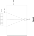
- Figure 1 illustrates a known image capture device 100 which uses a single camera 10 to obtain an image of a whole rack (12) holding sample test tubes labelled with barcodes (14).
- US2010046041 discloses a scanning apparatus which includes a flatbed scanning portion and a scanning module.
- the flatbed scanning portion includes a glass platform.
- the scanning module includes a scanning module case, a light source, multiple reflective mirrors, a lens, an optical sensing element, a printed circuit board and a metallic post.
- the metallic post is interconnected between the scanning module case and the printed circuit board.
- the printed circuit board is not in direct contact with the scanning module case so as to prevent defocus aberration resulting from thermal expansion.
- EP2682756 A2 represents the basis for the preamble of claim 1 and discloses an image capture device for capturing an image of barcodes of a plurality of test tubes held in a test tube rack.
- the height of the single camera imaging devices can be problematic for use with some automated robotic systems that have limited range of vertical arm movement.
- the height of the imaging device can be reduced using multiple cameras, where the resulting image is a composite of several images taken from a closer distance; however this solution increases complexity and cost of the imaging device.
- an image capture device for capturing an image of a test tube rack comprising a plurality of test tubes each having an individual barcode thereon, the image capture device comprising: an enclosure comprising a transparent window which, in use, is adjacent to the test tube rack to be imaged; at least one camera mounted within the enclosure to capture an image of the test tube rack; a lighting arrangement mounted within the enclosure, the lighting arrangement comprising at least one light source to illuminate the test tube rack through the transparent window; a mirror in an optical path between the at least one camera and the transparent window, the mirror arranged to relay light rays reflecting from the test tube rack to the at least one camera; and an interface for outputting the captured image to a host computer.
- an image capture device for capturing an image of barcodes of a plurality of test tubes held in a test tube rack, the plurality of test tubes each having an individual barcode thereon, the image capture device comprising: an enclosure comprising a transparent window which, in use, is adjacent to the test tube rack to be imaged; and a plurality of stationary components, the plurality of stationary components comprising: at least one camera mounted within the enclosure to capture an image of the barcodes; a lighting arrangement mounted within the enclosure, the lighting arrangement comprising at least one light source to illuminate the barcodes of the plurality of test tubes held in the test tube rack through the transparent window; a mirror in an optical path between the at least one camera and the transparent window, the mirror arranged to relay light rays reflecting from the barcodes of the plurality of test tubes held in the test tube rack to the at least one camera; and an interface for outputting the captured image to a host computer for decoding of said barcodes.
- the lighting arrangement may be mounted within the enclosure to provide generally uniform illumination across the whole transparent window and to reduce unwanted reflections.
- the barcodes may be positioned on the bases of the tubes (e.g. at the closed ends of the test tubes) or on the top of the tubes (for example on an outer surface of caps which seal the open ends of the tubes).
- the mirror inside the enclosure enables the camera to capture an image from the same distance as the known image capture device 100 (it will be a mirror image in the case of a single mirror) without the image suffering from any distortion, and the height of the image capture device can be made significantly smaller than the known image capture device 10.
- the mirror may be a first surface mirror.
- the mirror may be mounted within the enclosure at an angle that is equal to, or greater than 10 degrees relative to the transparent window and less than, or equal to 65 degrees relative to the transparent window.
- the mirror is mounted within the enclosure at an angle of 45 degrees relative to the transparent window. In another embodiment, the mirror is mounted within the enclosure at an angle that is greater than 45 degrees and less than or equal to 65 degrees relative to the transparent window. In yet another embodiment, the mirror is mounted within the enclosure at an angle that is greater than or equal to10 degrees and less than 45 degrees relative to the transparent window.
- the mirror may be mounted to one or any combination of: a base of the enclosure, a side wall of the enclosure, and a portion of a top of the enclosure which surrounds the transparent window.
- the at least one camera may be positioned lower than a height of the transparent window.
- the at least one camera may be mounted to one or any combination of: a base of the enclosure, a side wall of the enclosure, and a portion of a top of the enclosure which surrounds the transparent window.
- the enclosure may comprise a portion which extends vertically above a height of the transparent window and the at least one camera is mounted within said portion such that the at least one camera is positioned higher than the height of the transparent window.
- the image capture device may further comprise at least one further stationary mirror in the optical path between the at least one camera and the transparent window, the at least one further stationary mirror in combination with said mirror arranged to relay light rays reflecting from the test tube rack to the at least one camera.
- the at least one further stationary mirror may be a first surface mirror.
- the rack of tubes will be placed on top of the window and an image of the base of rack of tubes will be captured.
- the image capture device may be supported with its window above the tube rack.
- the lighting arrangement is mounted within the enclosure to provide generally uniform illumination across the whole transparent window and to reduce unwanted reflections.
- the barcodes of the plurality of test tubes held in the rack placed in contact or close proximity with the window will also be uniformly illuminated.
- generally uniform illumination it is meant that the illumination across the window is within a predefined range which is suitable for the dynamic range of the camera and optics being used.
- generally uniform illumination may be defined as providing illumination that varies by no more than approximately 20% from a maximum illumination. This enables high quality images to be captured and transferred to a host computer in order to decode barcodes present in the images.
- the barcodes of the plurality of test tubes held in the tube rack will reflect light back to the at least one camera.
- the nature of the reflection will depend on the material of the base of the tubes .
- the base surface of the tubes within a rack is generally matte, incoming light is reflected in a broad range of directions, i.e. there is diffuse reflection.
- the base surface of the tubes within a rack is generally glossy, there is will a mixture of diffuse reflection and specular reflection.
- Specular reflection is the mirror-like reflection of light in which the angle of incidence is equal to the angle of reflection. Reflection, in particular specular reflection where the light is directed straight back at the camera, is problematic for barcode reading as it can cause both the background material and the barcode to appear washed out, destroying the contrast that is required in order to read the barcode.
- the at least one light source needs to be positioned so that the angle of the light rays from it minimises reflections that may reduce the contrast of the barcodes on the test tubes.
- the direct reflection of the light from the mirror also needs to be avoided, which restricts the number of possible configurations for the light source(s).
- the optimal lighting avoids undesirable reflections whilst achieving a reasonably even illumination across the transparent window.
- the at least one light source directly illuminates the transparent window.
- the enclosure comprises a pair of opposed end walls and the at least one light source may be mounted adjacent to at least one end wall.
- a plurality of light sources may be symmetrically placed within the enclosure with light sources mounted adjacent to both end walls.
- the image capture device may further comprise at least one light blocking element arranged to block a subset of light ray angles radiating from the at least one light source.
- the lighting arrangement may comprise: a plurality of light sources comprising a first set of light sources and a second set of light sources mounted within the enclosure to directly illuminate the window, and at least one light blocking element arranged to block a subset of light ray angles radiating from only one of the first and second set of light sources.
- the first set of light sources may illuminate a first section of the transparent window and the second set of light sources may illuminate a second section of the transparent window and the first and second sections at least partially overlap to provide overlap regions.
- Each of the first and second set of light sources may comprise at least one array of light sources.
- the first set of light sources and the second set of light sources may be mounted at different angles relative to each other.
- Individual light sources may emit light of different intensity to achieve generally uniform illumination of the sample rack.
- the at least one light source indirectly illuminates the transparent window.
- the mirror may be arranged to reflect light emitted by the at least one light source towards the transparent window.
- At least one further mirror may be arranged to reflect light emitted by the at least one light source towards the transparent window.
- the at least one camera may have a resolution of at least 5 megapixels.
- the at least one camera may be a CCD camera or a CMOS camera.
- the transparent window may have dimensions which are approximately equal to dimensions of the test tube rack to be placed on the image capture device.
- the image capture device may further comprise a plurality of positioning elements to assist in correct positioning of the test tube rack on the transparent window.
- the image capture device may further comprise a controller which is configured to control capture of an image of the test tube rack placed on the image capture device.
- the controller may be mounted on a printed circuit board, the printed circuit board housed within the enclosure behind the mirror.
- the controller may be configured to receive a command to capture an image from the host computer via the interface.
- the controller may be configured to: increase the light intensity of light emitted by the at least one light source; control the at least one camera to capture an image of the test tube rack; decrease the light intensity of light emitted by the at least one light source; and transmit, via said interface, the captured image of the test tube rack to the host computer.
- the controller is configured to control the light intensity of light emitted by the at least one light source to provide generally uniform illumination across the whole transparent window.
- a computer program may be provided for the host computer to send commands to the imaging device and to decode the barcodes in the resulting image.
- the image capture device is designed to work with multiple racks available on the market, which includes various contrasts and colours of the printing of the barcodes and various surfaces of the tubes - from matte to glossy.
- a system comprising: an image capture device for capturing an image of barcodes of a plurality of test tubes held in a test tube rack, the plurality of test tubes each having an individual barcode thereon; and a host computer coupled to the image capture device; wherein the image capture device comprises: an enclosure comprising a transparent window which, in use, is adjacent to the test tube rack to be imaged; and a plurality of stationary components, the plurality of stationary components comprising: at least one camera mounted within the enclosure to capture an image of the barcodes; a lighting arrangement mounted within the enclosure, the lighting arrangement comprising at least one light source to illuminate the barcodes of the plurality of test tubes held in the test tube rack through the transparent window; a mirror in an optical path between the at least one camera and the transparent window, the mirror arranged to relay light rays reflecting from the barcodes of the plurality of test tubes held in the test tube rack to the at least one camera; and an interface for outputting the captured image to a host computer for de
- the invention further provides processor control code to implement the image capture system described above, for example on an embedded processor.
- the code may be provided on a carrier such as a disk, CD- or DVD-ROM, programmed memory such as read-only memory (Firmware), or on a data carrier such as an optical or electrical signal carrier.
- Code (and/or data) to implement embodiments of the invention may comprise source, object or executable code in a conventional programming language (interpreted or compiled) such as C, or assembly code, code for setting up or controlling an ASIC (Application Specific Integrated Circuit) or FPGA (Field Programmable Gate Array), or code for a hardware description language.
- ASIC Application Specific Integrated Circuit
- FPGA Field Programmable Gate Array
- code and/or data may be distributed between a plurality of coupled components in communication with one another.
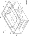
- FIG. 2 show an image capture device 200 according to the present invention.
- the image capture device 200 comprises an enclosure 201 having side walls, a base and a top (the base of the enclosure opposing the top).
- the top has a window 204 with dimensions (width and length) which generally match (i.e. is approximately equal to) those of a test tube rack to be placed on the device.
- the enclosure has the form of a generally rectangular box. It will be appreciated that other shapes of enclosure may be used provided the device is suitable for capturing an image of a test tube rack placed thereon.
- the image capture device 200 may comprise tube rack positioning elements 202 to correctly position a tube rack on the device,
- the enclosure 201 houses a camera 206. Whilst Figure 2 shows a single camera, more than one camera may be housed within the enclosure. The camera(s) 206 has a resolution of at least 5 megapixels.
- the enclosure 201 further houses a mirror 208. Whilst Figure 2 shows a single mirror, more than one mirror may be housed within the enclosure (described in more detail later).
- the mirror 208 may be a first surface mirror (otherwise known as a front surface mirror), which avoids added reflections that would otherwise be created from the glass surface of a conventional second surface mirror.
- the mirror 208 is in an optical path between the camera 206 and the transparent window 204, the mirror 208 being arranged to reflect light (which is reflected from the underside of the test tube rack) into the field of view of the camera 206.
- the mirror 208 enables the height of the image capture device 200 to be reduced whilst retaining the ability of the camera to obtain high quality images of barcodes of a plurality of test tubes held in the test tube rack so that the barcodes on each tube may be decoded.
- the camera 206 captures a single image of all of the barcodes of the plurality of test tubes held in the test tube rack.
- the enclosure 201 also houses a lighting arrangement; the lighting arrangement comprises at least one light source to illuminate test tube rack through the transparent window 204 in a generally uniform manner and to reduce unwanted reflections. When activated, the light source(s) illuminate the whole area of the transparent window.
- the lighting arrangement can be implemented in various ways which will be discussed in further detail later.
- the walls and base of the enclosure 201 are non-transparent in order to block out light from external sources.
- the top of the enclosure or at least the window 16 is transparent so that barcodes of a plurality of test tubes held in a test tube rack placed on the top of the device can be illuminated by the light sources and imaged by the camera 206 within the device.
- the image capture device 200 has no moving parts within the enclosure 201, all components housed within the enclosure are stationary (non-moveable components). That is, the camera 206, mirror 208 and light sources are stationary (do not move in operation) due to being fixed inside the enclosure by way of suitable mounting.
- Figures 3a shows the base 300 of a typical tube rack (in this case, a 96 tube rack), which is the object to be captured by the image capture device 200.
- a typical tube rack in this case, a 96 tube rack
- each circle indicates the position of a tube in the rack
- the base of each tube 14 is labelled with a barcode 302 (2D or otherwise), as shown in Figure 3b , which uniquely identifies the sample contained in each tube.
- embodiments extend to imaging barcodes which are placed on the top of the tubes (when the image capture device is supported with its window above the tube rack).
- Embodiments are not limited to an image capturing device for capturing an image of a 96 tube rack and can extend to capturing an image of any size test tube rack which holds a plurality of test tubes.
- the mirror 208 may be mounted within the enclosure 201 by a suitable fixing to one or more of: the base of the enclosure, a long side wall 205 of the enclosure and a portion of the top of the enclosure which surrounds the transparent window 204.
- the camera 206 may be mounted within the enclosure 201 by a suitable fixing to one or more of: the base of the enclosure, a long side wall 203 of the enclosure (opposing the long side wall 205 onto which the mirror 208 may be mounted) and a portion of the top of the enclosure which surrounds the transparent window 204
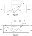
- Figure 4a is a side view of a first arrangement in which the mirror 208 is positioned at an angle, ⁇ of 45 degrees relative to a plane of the window 204 (plane A across the width of the window 204) e.g. relative to the rack 12, and the camera 206 is positioned so that the angle of reflection of the light reflected from the test tube rack is 90 degrees.
- the camera 206 is mounted such that the rear surface of the body of the camera 206 is parallel to the long side wall 203 of the enclosure (and may indeed be mounted to the long side wall 203) and the mirror 208 is in the field of view of the camera 206.
- the camera 206 is at a 90 degree angle relative to a plane (plane A) of the window 204 so that the camera 206 captures an image which is a mirror image of an image captured by the known image capture device 100 shown in Figure 1 .
- the enclosure 201 houses a printed circuit board (PCB) which includes a controller for controlling the light source(s) and the camera 206.
- the PCB may be positioned behind the mirror 208 such that the PCB is positioned directly below the sloping underside of the mirror 208.
- the height of the image capture device 200 can be reduced to below 85mm (this is approximately equal to the width of a 96 well test tube rack manufactured under the specifications of the industry standard defined by the Society for Biomolecular Screening (SBS)).
- the mirror 208 is mounted within the enclosure at an angle, ⁇ relative to a plane (plane A) of the window 204 that is greater than 45 degrees and less than or equal to 65 degrees relative to the transparent window 204, and the camera 206 is positioned so that the angle of the light reflected from the test tube rack is greater than 90 degrees.
- the height of the image capture device 200 will be higher than the arrangement shown in Figure 4a , the height of the image capture device 200 is still lower than the height of the known image capture device 100 shown in Figure 1 .
- the camera 206 In order for the camera 206 to capture an image equivalent to an image captured by the known image capture device 100 shown in Figure 1 , the camera 206 is tilted such that it is angled (at an angle greater than 90 degrees) relative to a plane (plane A) of the window 204 with the mirror 208 in the field of view of the camera 206.
- Figure 4b is a side view of a second arrangement in which the mirror 208 is positioned at an angle, ⁇ that is equal to, or greater than 10 degrees and less than 45 degrees relative to a plane of the window 204 (plane A across the width of the window 204) and the camera 206 is positioned so that the angle of reflection of the light reflected from the test tube rack is less than 90 degrees.
- the camera 206 In order for the camera 206 to capture an image equivalent to an image captured by the known image capture device 100 shown in Figure 1 , the camera 206 is tilted such that it is angled (at an angle less than 90 degrees) relative to a plane (plane A) of the window 204.
- the arrangement shown in Figure 4b is advantageous is that the height of the image capture device 200 is further reduced compared with the arrangement shown in Figure 4a .
- Figure 4c illustrates the height reduction which can be achieved using the arrangements shown in Figure 4a and Figure 4b .
- the height of the known image capture device 100 which shown in Figure 1 is h1.
- a shown in Figure 4c by using the arrangement shown in Figure 4a the height of the image capture device 200 is h2, where h2 ⁇ h1, and by using the arrangement shown in Figure 4b the height of the image capture device 200 is h3, where h3 ⁇ h2 ⁇ h1.
- embodiments of the present invention reduce the height of the image capture device while using a single low-cost camera.
- the enclosure 201 comprises a portion which extends vertically above a height of the transparent window and the camera 206 is mounted within said portion such that the camera 206 is positioned at a height which is higher than the height of the transparent window 204.
- the top of the enclosure 201 is not flat having a raised portion which houses the camera 206.
- the mirror 208 is positioned at an angle, ⁇ that is greater than 10 degrees and less than 45 degrees relative to a plane of the window 204 (plane A across the width of the window 204) and the camera 206 is positioned so that the angle of reflection of the light reflected from the test tube rack is less than 90 degrees.
- the camera 206 is tilted such that it is angled (at an angle less than 90 degrees) relative to a plane of the extended portion.
- a single mirror is in the optical path between the camera 206 and the transparent window 204
- multiple stationary mirrors may be present in the optical path between the camera 206 and the transparent window 204 and the multiple stationary mirrors in combination are arranged to relay light signals reflecting from the test tube rack to the at least one camera.
- Figure 5 is an example arrangement in which multiple stationary mirrors are present in the optical path between the camera 206 and the transparent window 204.
- a further stationary mirror 218 is provided so that an image of the barcodes of the plurality of test tubes 14 held in the test tube rack 12is reflected on the first stationary mirror 208, then reflected on the further stationary mirror 218, and then captured by the camera 206.
- At least one further stationary mirror 218 may be provided.
- the further stationary mirror(s) 218 may be a first surface mirror.
- the camera 206 may be mounted within the enclosure 201 so that the field of view of the camera is directed towards the top of the enclosure. In alternative arrangements, the camera 206 may be mounted within the enclosure 201 so that the field of view of the camera is directed towards the base of the enclosure.
- the path length of the optical path between the camera 206 and the transparent window 204 is the same and is equal to the path length of the optical path length between the camera 10 and the transparent window in the known image capture device 100 shown in Figure 1 .
- the use of multiple mirrors is advantageous because it enables the width of the image capture device 200 to be reduced as well as the height. Note that in the arrangement of Figure 4b having the mirror at a more acute angle requires the width of the image capture device to be increased in order to keep the path length of the optical path between the camera 206 and the transparent window 204 the same as the path length of the optical path length between the camera 10 and the transparent window in the known image capture device 100 shown in Figure 1 .
- imaging systems are generally pre-tuned or have user-configurable options that affect the amount of light captured by the sensor. These options include the optical size of the aperture and the exposure time. If the illumination is not evenly spread across the object there may be no single combination of exposure and aperture size that will result in a single image of high-enough quality. With high-dynamic range cameras this is less of a problem, but for a cost-effective CMOS camera the dynamic range may not be great enough. Accordingly, for a CMOS camera uneven illumination can result in total loss of contrast in over-exposed sections of the capture image and conversely total loss of contrast in under-exposed sections of the capture image. In addition, when lighting an object from the side, light rays reach the object from many different angles, which may potentially cause unwanted reflections.
- the lighting arrangement can be implemented in various ways.
- the light source(s) of the lighting arrangement directly illuminate the test tube rack through the transparent window 204. That is, no mirror is used to reflect light emitted by the light source(s) towards the transparent window 204.
- At least one light source is mounted on at least one side wall of the enclosure.
- at least one light source may be mounted on a short side wall 207 of the enclosure and optionally an additional at least one light source is mounted on the opposed short side wall 209 of the enclosure.
- the at least one light source may be mounted to the base of the enclosure and/or a portion of the top of the enclosure which surrounds the transparent window 204.
- the lighting needs to be placed to minimise the direct (specular) reflections from the sample rack (as if the camera was positioned on the base of the enclosure facing the transparent window) and additionally adjusted so that there is no direct reflection from the mirror 208.
- This may be achieved merely by optimal positioning and angling of the light source(s) without any light blocking elements being housed within the enclosure. In other embodiments, light blocking elements may be housed within the enclosure.
- one or more light blocking elements 214 may be housed within the enclosure 201 to block light from falling in these regions.
- the one or more light blocking elements 214 are arranged to block light rays which have an angle of incidence on the window 204 which is such that when the light ray is reflected in a single direction (specular reflection), the light is reflected directly back to the at least one camera 206.
- a preferred lighting arrangement is shown in Figure 6 . It will be appreciated that there are many lighting systems that reduce reflections that could be used to achieve a similar illumination result as the preferred lighting arrangement.
- the lighting arrangement shown in Figure 6 provides even illumination of and controls the reflections from the object being imaged (the plurality of test tubes held in the rack) and from the mirror 208 by using a combination of multiple light sources and multiple light blocking elements which are optimally positioned within the enclosure.
- the image capture device 200 contains multiple light sources positioned along two facing walls of the device.
- a first set of light sources 212a,b comprises an array of LEDs 212a mounted towards the lower edge of a short side wall 207 and a second array 212b mounted in a similar position on the opposed short side wall 209.
- a second set of light sources 212c,d comprises a first array of LEDs 212c mounted towards the upper edge of a short side wall 207 and a second array 212d mounted in a similar position on the opposed short side wall 209.
- Each set of light sources comprises an array in the form of a single line of 12 LEDs although it will be appreciated that different numbers of light sources could be used.
- White LEDs are used as these are a good general light source. However, other colour light sources may also be used in the cases where the use of different colours would improve the contrast of the resulting image. Also, emitters of illumination outside of visible spectrum can be employed, such as infrared light, or UV light (although this is often damaging for biological samples and generally not used if can be avoided).
- the light sources housed inside the enclosure 201 are stationary due to being fixed inside the enclosure by way of suitable mounting.
- the difference in intensity is balanced by arranging the light sources to control regions of overlap, i.e. regions of the window which are illuminated by more than one light source.
- the overlap regions will therefore be a mixture of intensity of light from different sources which overall gives rise to uniform light illumination on the window.
- Each blocking member 214 is in the form of a plate which extends generally perpendicular to the side wall of the enclosure.
- a blocking member 214 is mounted between the first set of light sources and the second set of light sources to prevent specular reflections from the first array of light sources.
- the unwanted reflections and the extent of the overlap regions are controlled by appropriate angling of the light sources.
- the light sources 212 may have the intensity and angles of the light emitted by the light sources 212 controlled electronically by the controller within the imaging device to help fine tune the illumination levels across the transparent window 204. This control may also be extended to the host computer, so the lighting may be adjusted based on the results of the image analysis.
- the same number of light sources is used in both the first and second light sources on each side of the enclosure but this is a parameter which could be adjusted to ensure uniform illumination.
- the light source(s) of the lighting arrangement directly illuminate the test tube rack through the transparent window 204.
- the light source(s) of the lighting arrangement indirectly illuminate the test tube rack through the transparent window 204 via one or more mirror. That is, one or more mirror is used to reflect light emitted by the light source(s) towards the transparent window 204.
- the mirror(s) arranged to relay light rays reflecting from the test tube rack to the at least one camera 206 are also used to reflect light emitted by the light source(s) towards the transparent window 204.
- the mirror(s) used to reflect light emitted by the light source(s) towards the transparent window 204 are different to the mirror(s) arranged to relay light rays reflecting from the test tube rack to the at least one camera 206.
- the enclosure 201 houses a printed circuit board (PCB) which includes a controller for controlling the light source(s) 212 and the camera 206.
- PCB printed circuit board
- the PCB 210 is shown in Figure 6 positioned behind the mirror 208 such that the PCB 210 is positioned directly below the sloping underside of the mirror 208, however the PCB 210 may be positioned at other locations inside the enclosure 201.
- Figure 7 is a schematic block diagram of the image capture device 200 and a host computer 700 which is coupled to the image capture device 200.
- the host computer 700 being external to the image capture device 200.
- a controller 218 is mounted on the PCB 210. It will be appreciated that other components will also be mounted on the PCB 210 but these have been omitted for simplicity.
- the controller 218 is coupled to the camera 206 via a suitable connection which may be a wired or wireless connection.
- the controller 218 is configured to control the camera 206 to capture an image of the barcodes of the plurality of test tubes held in test tube rack 12, and receive an image back from the camera 206 using this connection.
- the controller 218 is coupled to the light source(s) 212 via a suitable connection which may be a wired or wireless connection.
- the controller 218 is configured to control the intensity of light emitted by the light source(s) 212 using this connection.
- the image capture device 200 is coupled to the host computer 700 via an interface 216.
- the interface 216 is fixed within the enclosure 201. Whilst Figure 6 shows the interface 216 on a side wall of the enclosure 201, it will be appreciated that the interface may be located on the base of the enclosure or on a portion of the top of the enclosure which surrounds the transparent window 204.
- the controller 218 is coupled to the interface 216 and is configured to receive commands, transmitted from the host computer 700, via the interface 216.
- the controller 218 is further configured to transmit the image, received from the camera 206, to the host computer 700 via the interface 216 for decoding of the barcodes in the captured image.
- the image capture device 200 is coupled to the host computer 700 via a wired link (e.g. USB cable, Ethernet cable, HDMI cable, DIN cable etc.) in which case the interface 216 is a wired interface.
- a wired link e.g. USB cable, Ethernet cable, HDMI cable, DIN cable etc.
- the image capture device 200 is coupled to the host computer 700 via a wireless link (e.g. via a short-range RF technology such as Wi-Fi ® , ZigBee ® or Bluetooth ® ) in which case the interface 216 is a wireless interface.
- the image capture device 200 is connected to the host computer 700 and is initialised by a user opening and running an associated imaging software application running on a controller 704 of the host computer 700.
- the controller 704 is configured to send commands to the image capture device 200 via an interface 702 (wired or wireless) on the host computer 700.
- the controller 704 is further configured to receive image data, from the image capture device 200, via the interface 702.
- the host computer 700 may be any computing device able to connect to the image capture device 200 for example a mobile phone, a personal computer ("PC"), a tablet computer, a laptop computer etc.
- PC personal computer
- tablet computer a laptop computer etc.
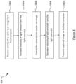
- Figure 8 is a flow chart for a process 800 performed by the controller 218 of the image capture device 200.
- the controller 218 receives, via the interface 216, a command from the host computer 700 to capture an image of the test tube rack 12.
- step S804 the controller 218 controls the light source(s) so that the light emitted from the light source(s) is increased.
- Step S804 may comprise the controller 218 turning the light source(s) on.
- step S804 may comprise the controller 218 increasing the light emitted from the light source(s) from a first illumination level (corresponding to when light is emitted from the light source(s)) to a higher second illumination level.
- the controller 218 controls the camera 206 to capture a single image of the barcodes of the plurality of test tubes held in the test tube rack 12 and in response receives image data of the captured image back from the camera 206.
- the light source(s) illuminate the whole area of the transparent window throughout the duration of a predetermined time period, and during this time period the controller 218 controls the camera 206 to capture the image.
- step S808 the controller 218 controls the light source(s) so that the light emitted from the light source(s) is decreased.
- Step S808 may comprise the controller 218 turning the light source(s) off.
- step S808 may comprise the controller 218 decreasing the light emitted from the light source(s) from a second illumination level to a lower first illumination level (corresponding to when light is emitted from the light source(s)).
- this advantageously protects light sensitive samples in the test tubes from unnecessary exposure to light and also to protect the eyes of the users operating the image capture device 200 from the bright light source(s) when the rack is not in place. Furthermore this reduces power consumption of the image capture device, extends the operating life of the light source(s), and avoids overheating of the image capture device.
- the controller 218 transmits the image data, received from the camera 206, to the host computer 700 via the interface 216.
- the imaging software application running on the controller 704 of the host computer 700 receives the image data and performs image processing to decode the barcodes in the captured image.
- the imaging software application may flip the received image horizontally (in the case of a single mirror being used to relay light rays reflecting from the test tube rack to the camera 206) so that the resulting image corresponds to that which would be captured using the known image capture device 100.
- the flipping of the captured image may alternatively be carried out on the image capture device e.g. by the camera 206 or controller 218.
- the controller 218 may be implemented in code (software and/or firmware) stored on a memory (not shown in the figure) comprising one or more storage media, and arranged for execution on a processor comprising on or more processing units.
- the code is configured so as when fetched from the memory and executed on the processor to perform operations in line with embodiments discussed above.
- some or all of the functionality of the controller 218 is implemented in dedicated hardware circuitry, or configurable hardware circuitry like an FPGA.
Landscapes
- Physics & Mathematics (AREA)
- Engineering & Computer Science (AREA)
- Electromagnetism (AREA)
- General Health & Medical Sciences (AREA)
- Health & Medical Sciences (AREA)
- General Physics & Mathematics (AREA)
- Theoretical Computer Science (AREA)
- Toxicology (AREA)
- Computer Vision & Pattern Recognition (AREA)
- Artificial Intelligence (AREA)
- Analytical Chemistry (AREA)
- Biochemistry (AREA)
- Chemical & Material Sciences (AREA)
- Pathology (AREA)
- Immunology (AREA)
- Life Sciences & Earth Sciences (AREA)
- Studio Devices (AREA)
- Investigating Materials By The Use Of Optical Means Adapted For Particular Applications (AREA)
- Image Input (AREA)
- Investigating Or Analysing Materials By Optical Means (AREA)
Claims (15)
- Dispositif de capture d'image (200) pour capturer une image de codes à barres d'une pluralité de tubes à essai (14) maintenus dans un support de tubes à essai (12), la pluralité des tubes à essai comportant chacun un code à barres individuel (302) sur celui-ci, le dispositif de capture d'image comprenant :une enceinte (201) comprenant une fenêtre transparente (204) pour supporter le support de tubes à essai à reproduire en image, etune pluralité d'éléments fixes non mobiles, la pluralité d'éléments fixes non mobiles comprenant :au moins un appareil de prise de vues (206) monté à l'intérieur de l'enceinte pour capturer une image des codes à barres,un agencement d'éclairage monté à l'intérieur de l'enceinte, l'agencement d'éclairage comprenant au moins une source de lumière (212) pour éclairer les codes à barres de la pluralité des tubes à essai maintenus dans le support de tubes à essai à travers la fenêtre transparente,une interface (216) pour délivrer l'image capturée à un ordinateur hôte (700),caractérisé parun miroir (208) dans un trajet optique entre l'au moins un appareil de prise de vues et la fenêtre transparente, le miroir permettant de renvoyer des rayons de lumière réfléchis à partir des codes à barres de la pluralité des tubes à essai maintenus dans le support de tubes à essai vers l'au moins un appareil de prise de vues.
- Dispositif de capture d'image selon la revendication 1, dans lequel le miroir est monté à l'intérieur de l'enceinte à un angle qui est égal ou supérieur à 10 degrés par rapport à la fenêtre transparente, et inférieur ou égal à 65 degrés par rapport à la fenêtre transparente,
optionnellement dans lequel le miroir est monté à l'intérieur de l'enceinte à un angle de 45 degrés par rapport à la fenêtre transparente. - Dispositif de capture d'image selon la revendication 1, dans lequel le miroir est monté à l'intérieur de l'enceinte à un angle qui est supérieur à 45 degrés et inférieur ou égal à 65 degrés par rapport à la fenêtre transparente.
- Dispositif de capture d'image selon la revendication 1, dans lequel le miroir est monté à l'intérieur de l'enceinte à un angle qui est égal ou supérieur à 10 degrés et inférieur à 45 degrés par rapport à la fenêtre transparente.
- Dispositif de capture d'image selon l'une quelconque des revendications précédentes, dans lequel l'au moins un appareil de prise de vues est positionné à une hauteur inférieure à la hauteur de la fenêtre transparente, dans lequel de préférence l'au moins un appareil de prise de vues est monté sur une ou une combinaison d'une base de l'enceinte, une paroi latérale de l'enceinte, et une partie du haut de l'enceinte qui entoure la fenêtre transparente.
- Dispositif de capture d'image selon l'une quelconque des revendications précédentes, où le dispositif de capture d'image comprend en outre au moins un miroir fixe supplémentaire (218) dans le trajet optique entre l'au moins un appareil de prise de vues et la fenêtre transparente, l'au moins un miroir fixe supplémentaire, combiné avec ledit miroir, étant agencé pour renvoyer des rayons de lumière réfléchis par le support de tubes à essai vers l'au moins un appareil de prise de vues.
- Dispositif de capture d'image selon l'une quelconque des revendications précédentes, dans lequel l'agencement d'éclairage est monté à l'intérieur de l'enceinte pour fournir un éclairage généralement uniforme à travers la fenêtre transparente entière et pour réduire des reflets indésirables.
- Dispositif de capture d'image selon l'une quelconque des revendications précédentes, dans lequel l'enceinte comprend une paire de parois d'extrémité opposées (207, 209) et l'au moins une source de lumière est montée de façon adjacente à au moins une paroi d'extrémité, dans lequel de préférence une pluralité de sources de lumière sont placées de façon symétrique à l'intérieur de l'enceinte, les sources de lumière étant montées de façon adjacente aux deux parois d'extrémité.
- Dispositif de capture d'image selon l'une quelconque des revendications précédentes, dans lequel le dispositif de capture d'image comprend en outre au moins un élément de blocage de lumière (214) agencé pour bloquer un sous-ensemble d'angles de rayon de lumière émis par l'au moins une source de lumière.
- Dispositif de capture d'image selon l'une quelconque des revendications 1 à 7, dans lequel l'agencement d'éclairage comprend :une pluralité de sources de lumière comprenant un premier ensemble de sources de lumière et un deuxième ensemble de sources de lumière montés à l'intérieur de l'enceinte pour éclairer directement la fenêtre, etau moins un élément de blocage de lumière agencé pour bloquer un sous-ensemble d'angles de rayon de lumière émis à partir d'un seul du premier et du deuxième ensemble de sources de lumière,dans lequel de préférence le premier ensemble de sources de lumière éclaire une première section de la fenêtre transparente et le deuxième ensemble de sources de lumière éclaire une deuxième section de la fenêtre transparente et les première et deuxième sections se chevauchent au moins partiellement pour fournir des régions de chevauchement.
- Dispositif de capture d'image selon l'une quelconque des revendications 1 à 10, dans lequel l'au moins une source de lumière éclaire indirectement la fenêtre transparente.
- Dispositif de capture d'image selon l'une quelconque des revendications précédentes, dans lequel l'au moins un appareil de prise de vues a une résolution d'au moins 5 mégapixels.
- Dispositif de capture d'image selon l'une quelconque des revendications précédentes, comprenant en outre un dispositif de contrôle (218) qui est configuré pour contrôler une capture d'une image du support de tubes à essai placé sur le dispositif de capture d'image, dans lequel le dispositif de contrôle est configuré de préférence pour :augmenter l'intensité de lumière émise par l'au moins une source de lumière,contrôler l'au moins un appareil de prise de vues pour capturer une image du support de tubes à essai,diminuer l'intensité de la lumière émise par l'au moins une source de lumière, ettransmettre, via ladite interface, l'image capturée du support de tubes à essai à l'ordinateur hôte.
- Dispositif de capture d'image selon l'une quelconque des revendications précédentes, dans lequel le miroir est un premier miroir de surface.
- Système comprenant :un dispositif de capture d'image selon l'une quelconque des revendications précédentes, etun ordinateur hôte (700) couplé au dispositif de capture d'image.
Applications Claiming Priority (2)
| Application Number | Priority Date | Filing Date | Title |
|---|---|---|---|
| GBGB1712421.5A GB201712421D0 (en) | 2017-08-02 | 2017-08-02 | Device for reading barcodes |
| PCT/GB2017/053631 WO2019025747A1 (fr) | 2017-08-02 | 2017-12-01 | Dispositif de lecture de codes à barres |
Publications (2)
| Publication Number | Publication Date |
|---|---|
| EP3662405A1 EP3662405A1 (fr) | 2020-06-10 |
| EP3662405B1 true EP3662405B1 (fr) | 2023-06-07 |
Family
ID=59778866
Family Applications (1)
| Application Number | Title | Priority Date | Filing Date |
|---|---|---|---|
| EP17809358.9A Active EP3662405B1 (fr) | 2017-08-02 | 2017-12-01 | Dispositif de lecture de codes à barres |
Country Status (4)
| Country | Link |
|---|---|
| US (1) | US20200191812A1 (fr) |
| EP (1) | EP3662405B1 (fr) |
| GB (1) | GB201712421D0 (fr) |
| WO (1) | WO2019025747A1 (fr) |
Families Citing this family (6)
| Publication number | Priority date | Publication date | Assignee | Title |
|---|---|---|---|---|
| CN111538101B (zh) * | 2020-04-18 | 2024-10-29 | 桂林优利特医疗电子有限公司 | 一种试管检测装置 |
| US12412651B2 (en) * | 2021-03-23 | 2025-09-09 | Quantgene Inc. | Sample tube rack based transfer, management and tracking |
| US12475344B2 (en) * | 2021-06-23 | 2025-11-18 | Liconic Ag | Code scanner for capturing codes on tubes in a tube rack |
| CN114118324A (zh) * | 2021-11-26 | 2022-03-01 | 上海品峰医疗科技有限公司 | 一种可实现试管快速扫描定位的装置 |
| DE102021133125A1 (de) * | 2021-12-14 | 2023-06-15 | Krones Aktiengesellschaft | Getränkekasten mit Zentrierfunktion für Flaschen und zusätzlicher Aussparung für Serialisierungsanwendung |
| EP4206679B1 (fr) | 2021-12-29 | 2026-05-06 | TECAN Trading AG | Lecteure optique pour embout de pipette |
Citations (1)
| Publication number | Priority date | Publication date | Assignee | Title |
|---|---|---|---|---|
| WO2005038705A2 (fr) * | 2003-10-10 | 2005-04-28 | Ruling Optics Llc | Dispositif de balayage rapide comprenant un miroir rotatif et un systeme de traitement de l'image |
Family Cites Families (8)
| Publication number | Priority date | Publication date | Assignee | Title |
|---|---|---|---|---|
| US5053612A (en) * | 1990-03-28 | 1991-10-01 | Tech-S, Inc. | Barcode badge and ticket reader employing beam splitting |
| US5907411A (en) * | 1996-07-17 | 1999-05-25 | Microtek International, Inc. | Multi-resolution transmissive and reflective optical scanner |
| US7533819B2 (en) * | 2007-01-31 | 2009-05-19 | Symbol Technologies, Inc. | Dual camera assembly for an imaging-based bar code reader |
| US8505824B2 (en) * | 2007-06-28 | 2013-08-13 | Symbol Technologies, Inc. | Bar code readers having multifold mirrors |
| TWI384860B (zh) * | 2008-08-22 | 2013-02-01 | Primax Electronics Ltd | 可防止失焦現象之掃描裝置 |
| US8434686B2 (en) * | 2010-01-11 | 2013-05-07 | Cognex Corporation | Swipe scanner employing a vision system |
| GB2501504B (en) * | 2012-04-25 | 2015-07-22 | Ziath Ltd | Device for reading barcodes |
| ES2692743T3 (es) * | 2014-03-06 | 2018-12-04 | Skidata Ag | Escáner de código de barras 2D |
-
2017
- 2017-08-02 GB GBGB1712421.5A patent/GB201712421D0/en not_active Ceased
- 2017-12-01 US US16/633,213 patent/US20200191812A1/en not_active Abandoned
- 2017-12-01 WO PCT/GB2017/053631 patent/WO2019025747A1/fr not_active Ceased
- 2017-12-01 EP EP17809358.9A patent/EP3662405B1/fr active Active
Patent Citations (1)
| Publication number | Priority date | Publication date | Assignee | Title |
|---|---|---|---|---|
| WO2005038705A2 (fr) * | 2003-10-10 | 2005-04-28 | Ruling Optics Llc | Dispositif de balayage rapide comprenant un miroir rotatif et un systeme de traitement de l'image |
Also Published As
| Publication number | Publication date |
|---|---|
| EP3662405A1 (fr) | 2020-06-10 |
| GB201712421D0 (en) | 2017-09-13 |
| WO2019025747A1 (fr) | 2019-02-07 |
| US20200191812A1 (en) | 2020-06-18 |
Similar Documents
| Publication | Publication Date | Title |
|---|---|---|
| EP3662405B1 (fr) | Dispositif de lecture de codes à barres | |
| US20130306729A1 (en) | Device for reading barcodes | |
| EP2781910B1 (fr) | Module de lecteur portatif, lecteur portatif et procédé d'analyse quantitative d'un dosage | |
| JP7003241B2 (ja) | 貼り付けスライド判定システム | |
| EP2996064B1 (fr) | Dispositif stationnaire de lecture de code d'informations | |
| JP6293223B2 (ja) | フリッカー修正エイマおよび交替する照明を有する端末 | |
| CN111279199B (zh) | 用于禁用转盘旋转的安全光幕 | |
| JP2017055396A5 (fr) | ||
| CN102334130A (zh) | 具有双功能照明光组件的成像读取器和方法 | |
| CN102334131A (zh) | 用于成像读取器的紧凑型成像引擎 | |
| GB2537887A (en) | System and method for identifying a sample container, a reagent container or a rack | |
| US10721368B2 (en) | Slide rack determination system | |
| EP2921846B1 (fr) | Module de lecteur portatif, lecteur portatif et procédé d'analyse quantitative d'un dosage | |
| JPH06139398A (ja) | 2次元コードスキャナ | |
| US20250138003A1 (en) | Measurement system | |
| JP6930252B2 (ja) | 光学的情報読取装置 |
Legal Events
| Date | Code | Title | Description |
|---|---|---|---|
| STAA | Information on the status of an ep patent application or granted ep patent |
Free format text: STATUS: UNKNOWN |
|
| STAA | Information on the status of an ep patent application or granted ep patent |
Free format text: STATUS: THE INTERNATIONAL PUBLICATION HAS BEEN MADE |
|
| PUAI | Public reference made under article 153(3) epc to a published international application that has entered the european phase |
Free format text: ORIGINAL CODE: 0009012 |
|
| STAA | Information on the status of an ep patent application or granted ep patent |
Free format text: STATUS: REQUEST FOR EXAMINATION WAS MADE |
|
| 17P | Request for examination filed |
Effective date: 20200228 |
|
| AK | Designated contracting states |
Kind code of ref document: A1 Designated state(s): AL AT BE BG CH CY CZ DE DK EE ES FI FR GB GR HR HU IE IS IT LI LT LU LV MC MK MT NL NO PL PT RO RS SE SI SK SM TR |
|
| AX | Request for extension of the european patent |
Extension state: BA ME |
|
| DAV | Request for validation of the european patent (deleted) | ||
| DAX | Request for extension of the european patent (deleted) | ||
| STAA | Information on the status of an ep patent application or granted ep patent |
Free format text: STATUS: EXAMINATION IS IN PROGRESS |
|
| 17Q | First examination report despatched |
Effective date: 20211112 |
|
| GRAP | Despatch of communication of intention to grant a patent |
Free format text: ORIGINAL CODE: EPIDOSNIGR1 |
|
| STAA | Information on the status of an ep patent application or granted ep patent |
Free format text: STATUS: GRANT OF PATENT IS INTENDED |
|
| INTG | Intention to grant announced |
Effective date: 20221103 |
|
| GRAS | Grant fee paid |
Free format text: ORIGINAL CODE: EPIDOSNIGR3 |
|
| GRAA | (expected) grant |
Free format text: ORIGINAL CODE: 0009210 |
|
| STAA | Information on the status of an ep patent application or granted ep patent |
Free format text: STATUS: THE PATENT HAS BEEN GRANTED |
|
| AK | Designated contracting states |
Kind code of ref document: B1 Designated state(s): AL AT BE BG CH CY CZ DE DK EE ES FI FR GB GR HR HU IE IS IT LI LT LU LV MC MK MT NL NO PL PT RO RS SE SI SK SM TR |
|
| REG | Reference to a national code |
Ref country code: GB Ref legal event code: FG4D |
|
| REG | Reference to a national code |
Ref country code: CH Ref legal event code: EP Ref country code: AT Ref legal event code: REF Ref document number: 1577197 Country of ref document: AT Kind code of ref document: T Effective date: 20230615 |
|
| REG | Reference to a national code |
Ref country code: DE Ref legal event code: R096 Ref document number: 602017069797 Country of ref document: DE |
|
| REG | Reference to a national code |
Ref country code: NL Ref legal event code: FP |
|
| REG | Reference to a national code |
Ref country code: LT Ref legal event code: MG9D |
|
| P01 | Opt-out of the competence of the unified patent court (upc) registered |
Effective date: 20230913 |
|
| PG25 | Lapsed in a contracting state [announced via postgrant information from national office to epo] |
Ref country code: SE Free format text: LAPSE BECAUSE OF FAILURE TO SUBMIT A TRANSLATION OF THE DESCRIPTION OR TO PAY THE FEE WITHIN THE PRESCRIBED TIME-LIMIT Effective date: 20230607 Ref country code: NO Free format text: LAPSE BECAUSE OF FAILURE TO SUBMIT A TRANSLATION OF THE DESCRIPTION OR TO PAY THE FEE WITHIN THE PRESCRIBED TIME-LIMIT Effective date: 20230907 Ref country code: ES Free format text: LAPSE BECAUSE OF FAILURE TO SUBMIT A TRANSLATION OF THE DESCRIPTION OR TO PAY THE FEE WITHIN THE PRESCRIBED TIME-LIMIT Effective date: 20230607 |
|
| REG | Reference to a national code |
Ref country code: AT Ref legal event code: MK05 Ref document number: 1577197 Country of ref document: AT Kind code of ref document: T Effective date: 20230607 |
|
| PG25 | Lapsed in a contracting state [announced via postgrant information from national office to epo] |
Ref country code: RS Free format text: LAPSE BECAUSE OF FAILURE TO SUBMIT A TRANSLATION OF THE DESCRIPTION OR TO PAY THE FEE WITHIN THE PRESCRIBED TIME-LIMIT Effective date: 20230607 Ref country code: LV Free format text: LAPSE BECAUSE OF FAILURE TO SUBMIT A TRANSLATION OF THE DESCRIPTION OR TO PAY THE FEE WITHIN THE PRESCRIBED TIME-LIMIT Effective date: 20230607 Ref country code: LT Free format text: LAPSE BECAUSE OF FAILURE TO SUBMIT A TRANSLATION OF THE DESCRIPTION OR TO PAY THE FEE WITHIN THE PRESCRIBED TIME-LIMIT Effective date: 20230607 Ref country code: HR Free format text: LAPSE BECAUSE OF FAILURE TO SUBMIT A TRANSLATION OF THE DESCRIPTION OR TO PAY THE FEE WITHIN THE PRESCRIBED TIME-LIMIT Effective date: 20230607 Ref country code: GR Free format text: LAPSE BECAUSE OF FAILURE TO SUBMIT A TRANSLATION OF THE DESCRIPTION OR TO PAY THE FEE WITHIN THE PRESCRIBED TIME-LIMIT Effective date: 20230908 |
|
| PG25 | Lapsed in a contracting state [announced via postgrant information from national office to epo] |
Ref country code: FI Free format text: LAPSE BECAUSE OF FAILURE TO SUBMIT A TRANSLATION OF THE DESCRIPTION OR TO PAY THE FEE WITHIN THE PRESCRIBED TIME-LIMIT Effective date: 20230607 |
|
| PG25 | Lapsed in a contracting state [announced via postgrant information from national office to epo] |
Ref country code: SK Free format text: LAPSE BECAUSE OF FAILURE TO SUBMIT A TRANSLATION OF THE DESCRIPTION OR TO PAY THE FEE WITHIN THE PRESCRIBED TIME-LIMIT Effective date: 20230607 |
|
| PG25 | Lapsed in a contracting state [announced via postgrant information from national office to epo] |
Ref country code: IS Free format text: LAPSE BECAUSE OF FAILURE TO SUBMIT A TRANSLATION OF THE DESCRIPTION OR TO PAY THE FEE WITHIN THE PRESCRIBED TIME-LIMIT Effective date: 20231007 |
|
| PG25 | Lapsed in a contracting state [announced via postgrant information from national office to epo] |
Ref country code: SM Free format text: LAPSE BECAUSE OF FAILURE TO SUBMIT A TRANSLATION OF THE DESCRIPTION OR TO PAY THE FEE WITHIN THE PRESCRIBED TIME-LIMIT Effective date: 20230607 Ref country code: SK Free format text: LAPSE BECAUSE OF FAILURE TO SUBMIT A TRANSLATION OF THE DESCRIPTION OR TO PAY THE FEE WITHIN THE PRESCRIBED TIME-LIMIT Effective date: 20230607 Ref country code: RO Free format text: LAPSE BECAUSE OF FAILURE TO SUBMIT A TRANSLATION OF THE DESCRIPTION OR TO PAY THE FEE WITHIN THE PRESCRIBED TIME-LIMIT Effective date: 20230607 Ref country code: PT Free format text: LAPSE BECAUSE OF FAILURE TO SUBMIT A TRANSLATION OF THE DESCRIPTION OR TO PAY THE FEE WITHIN THE PRESCRIBED TIME-LIMIT Effective date: 20231009 Ref country code: IS Free format text: LAPSE BECAUSE OF FAILURE TO SUBMIT A TRANSLATION OF THE DESCRIPTION OR TO PAY THE FEE WITHIN THE PRESCRIBED TIME-LIMIT Effective date: 20231007 Ref country code: EE Free format text: LAPSE BECAUSE OF FAILURE TO SUBMIT A TRANSLATION OF THE DESCRIPTION OR TO PAY THE FEE WITHIN THE PRESCRIBED TIME-LIMIT Effective date: 20230607 Ref country code: CZ Free format text: LAPSE BECAUSE OF FAILURE TO SUBMIT A TRANSLATION OF THE DESCRIPTION OR TO PAY THE FEE WITHIN THE PRESCRIBED TIME-LIMIT Effective date: 20230607 Ref country code: AT Free format text: LAPSE BECAUSE OF FAILURE TO SUBMIT A TRANSLATION OF THE DESCRIPTION OR TO PAY THE FEE WITHIN THE PRESCRIBED TIME-LIMIT Effective date: 20230607 |
|
| PG25 | Lapsed in a contracting state [announced via postgrant information from national office to epo] |
Ref country code: PL Free format text: LAPSE BECAUSE OF FAILURE TO SUBMIT A TRANSLATION OF THE DESCRIPTION OR TO PAY THE FEE WITHIN THE PRESCRIBED TIME-LIMIT Effective date: 20230607 |
|
| REG | Reference to a national code |
Ref country code: DE Ref legal event code: R097 Ref document number: 602017069797 Country of ref document: DE |
|
| PLBE | No opposition filed within time limit |
Free format text: ORIGINAL CODE: 0009261 |
|
| STAA | Information on the status of an ep patent application or granted ep patent |
Free format text: STATUS: NO OPPOSITION FILED WITHIN TIME LIMIT |
|
| PG25 | Lapsed in a contracting state [announced via postgrant information from national office to epo] |
Ref country code: DK Free format text: LAPSE BECAUSE OF FAILURE TO SUBMIT A TRANSLATION OF THE DESCRIPTION OR TO PAY THE FEE WITHIN THE PRESCRIBED TIME-LIMIT Effective date: 20230607 |
|
| PG25 | Lapsed in a contracting state [announced via postgrant information from national office to epo] |
Ref country code: SI Free format text: LAPSE BECAUSE OF FAILURE TO SUBMIT A TRANSLATION OF THE DESCRIPTION OR TO PAY THE FEE WITHIN THE PRESCRIBED TIME-LIMIT Effective date: 20230607 |
|
| 26N | No opposition filed |
Effective date: 20240308 |
|
| PG25 | Lapsed in a contracting state [announced via postgrant information from national office to epo] |
Ref country code: SI Free format text: LAPSE BECAUSE OF FAILURE TO SUBMIT A TRANSLATION OF THE DESCRIPTION OR TO PAY THE FEE WITHIN THE PRESCRIBED TIME-LIMIT Effective date: 20230607 Ref country code: IT Free format text: LAPSE BECAUSE OF FAILURE TO SUBMIT A TRANSLATION OF THE DESCRIPTION OR TO PAY THE FEE WITHIN THE PRESCRIBED TIME-LIMIT Effective date: 20230607 |
|
| REG | Reference to a national code |
Ref country code: CH Ref legal event code: PL |
|
| PG25 | Lapsed in a contracting state [announced via postgrant information from national office to epo] |
Ref country code: LU Free format text: LAPSE BECAUSE OF NON-PAYMENT OF DUE FEES Effective date: 20231201 |
|
| PG25 | Lapsed in a contracting state [announced via postgrant information from national office to epo] |
Ref country code: MC Free format text: LAPSE BECAUSE OF FAILURE TO SUBMIT A TRANSLATION OF THE DESCRIPTION OR TO PAY THE FEE WITHIN THE PRESCRIBED TIME-LIMIT Effective date: 20230607 |
|
| REG | Reference to a national code |
Ref country code: BE Ref legal event code: MM Effective date: 20231231 |
|
| PG25 | Lapsed in a contracting state [announced via postgrant information from national office to epo] |
Ref country code: MC Free format text: LAPSE BECAUSE OF FAILURE TO SUBMIT A TRANSLATION OF THE DESCRIPTION OR TO PAY THE FEE WITHIN THE PRESCRIBED TIME-LIMIT Effective date: 20230607 Ref country code: LU Free format text: LAPSE BECAUSE OF NON-PAYMENT OF DUE FEES Effective date: 20231201 |
|
| REG | Reference to a national code |
Ref country code: IE Ref legal event code: MM4A |
|
| PG25 | Lapsed in a contracting state [announced via postgrant information from national office to epo] |
Ref country code: IE Free format text: LAPSE BECAUSE OF NON-PAYMENT OF DUE FEES Effective date: 20231201 |
|
| PG25 | Lapsed in a contracting state [announced via postgrant information from national office to epo] |
Ref country code: BE Free format text: LAPSE BECAUSE OF NON-PAYMENT OF DUE FEES Effective date: 20231231 |
|
| PG25 | Lapsed in a contracting state [announced via postgrant information from national office to epo] |
Ref country code: FR Free format text: LAPSE BECAUSE OF NON-PAYMENT OF DUE FEES Effective date: 20231231 |
|
| PG25 | Lapsed in a contracting state [announced via postgrant information from national office to epo] |
Ref country code: CH Free format text: LAPSE BECAUSE OF NON-PAYMENT OF DUE FEES Effective date: 20231231 |
|
| PG25 | Lapsed in a contracting state [announced via postgrant information from national office to epo] |
Ref country code: IE Free format text: LAPSE BECAUSE OF NON-PAYMENT OF DUE FEES Effective date: 20231201 Ref country code: FR Free format text: LAPSE BECAUSE OF NON-PAYMENT OF DUE FEES Effective date: 20231231 Ref country code: CH Free format text: LAPSE BECAUSE OF NON-PAYMENT OF DUE FEES Effective date: 20231231 Ref country code: BE Free format text: LAPSE BECAUSE OF NON-PAYMENT OF DUE FEES Effective date: 20231231 |
|
| PG25 | Lapsed in a contracting state [announced via postgrant information from national office to epo] |
Ref country code: BG Free format text: LAPSE BECAUSE OF FAILURE TO SUBMIT A TRANSLATION OF THE DESCRIPTION OR TO PAY THE FEE WITHIN THE PRESCRIBED TIME-LIMIT Effective date: 20230607 |
|
| PG25 | Lapsed in a contracting state [announced via postgrant information from national office to epo] |
Ref country code: BG Free format text: LAPSE BECAUSE OF FAILURE TO SUBMIT A TRANSLATION OF THE DESCRIPTION OR TO PAY THE FEE WITHIN THE PRESCRIBED TIME-LIMIT Effective date: 20230607 |
|
| PGFP | Annual fee paid to national office [announced via postgrant information from national office to epo] |
Ref country code: GB Payment date: 20250212 Year of fee payment: 8 |
|
| PG25 | Lapsed in a contracting state [announced via postgrant information from national office to epo] |
Ref country code: CY Free format text: LAPSE BECAUSE OF FAILURE TO SUBMIT A TRANSLATION OF THE DESCRIPTION OR TO PAY THE FEE WITHIN THE PRESCRIBED TIME-LIMIT; INVALID AB INITIO Effective date: 20171201 |
|
| PG25 | Lapsed in a contracting state [announced via postgrant information from national office to epo] |
Ref country code: HU Free format text: LAPSE BECAUSE OF FAILURE TO SUBMIT A TRANSLATION OF THE DESCRIPTION OR TO PAY THE FEE WITHIN THE PRESCRIBED TIME-LIMIT; INVALID AB INITIO Effective date: 20171201 |
|
| PG25 | Lapsed in a contracting state [announced via postgrant information from national office to epo] |
Ref country code: TR Free format text: LAPSE BECAUSE OF FAILURE TO SUBMIT A TRANSLATION OF THE DESCRIPTION OR TO PAY THE FEE WITHIN THE PRESCRIBED TIME-LIMIT Effective date: 20230607 |
|
| PGFP | Annual fee paid to national office [announced via postgrant information from national office to epo] |
Ref country code: NL Payment date: 20251226 Year of fee payment: 9 |
|
| PGFP | Annual fee paid to national office [announced via postgrant information from national office to epo] |
Ref country code: DE Payment date: 20251229 Year of fee payment: 9 |