EP3662544B1 - Kabelanordnung mit zugentlastung - Google Patents
Kabelanordnung mit zugentlastung Download PDFInfo
- Publication number
- EP3662544B1 EP3662544B1 EP18840193.9A EP18840193A EP3662544B1 EP 3662544 B1 EP3662544 B1 EP 3662544B1 EP 18840193 A EP18840193 A EP 18840193A EP 3662544 B1 EP3662544 B1 EP 3662544B1
- Authority
- EP
- European Patent Office
- Prior art keywords
- cable
- retainer
- connector
- accordance
- clamps
- Prior art date
- Legal status (The legal status is an assumption and is not a legal conclusion. Google has not performed a legal analysis and makes no representation as to the accuracy of the status listed.)
- Active
Links
Images



Classifications
-
- H—ELECTRICITY
- H01—ELECTRIC ELEMENTS
- H01R—ELECTRICALLY-CONDUCTIVE CONNECTIONS; STRUCTURAL ASSOCIATIONS OF A PLURALITY OF MUTUALLY-INSULATED ELECTRICAL CONNECTING ELEMENTS; COUPLING DEVICES; CURRENT COLLECTORS
- H01R13/00—Details of coupling devices of the kinds covered by groups H01R12/70 or H01R24/00 - H01R33/00
- H01R13/58—Means for relieving strain on wire connection, e.g. cord grip, for avoiding loosening of connections between wires and terminals within a coupling device terminating a cable
- H01R13/582—Means for relieving strain on wire connection, e.g. cord grip, for avoiding loosening of connections between wires and terminals within a coupling device terminating a cable the cable being clamped between assembled parts of the housing
- H01R13/5825—Means for relieving strain on wire connection, e.g. cord grip, for avoiding loosening of connections between wires and terminals within a coupling device terminating a cable the cable being clamped between assembled parts of the housing the means comprising additional parts captured between housing parts and cable
-
- H—ELECTRICITY
- H01—ELECTRIC ELEMENTS
- H01R—ELECTRICALLY-CONDUCTIVE CONNECTIONS; STRUCTURAL ASSOCIATIONS OF A PLURALITY OF MUTUALLY-INSULATED ELECTRICAL CONNECTING ELEMENTS; COUPLING DEVICES; CURRENT COLLECTORS
- H01R13/00—Details of coupling devices of the kinds covered by groups H01R12/70 or H01R24/00 - H01R33/00
- H01R13/02—Contact members
- H01R13/15—Pins, blades or sockets having separate spring member for producing or increasing contact pressure
- H01R13/187—Pins, blades or sockets having separate spring member for producing or increasing contact pressure with spring member in the socket
-
- H—ELECTRICITY
- H01—ELECTRIC ELEMENTS
- H01R—ELECTRICALLY-CONDUCTIVE CONNECTIONS; STRUCTURAL ASSOCIATIONS OF A PLURALITY OF MUTUALLY-INSULATED ELECTRICAL CONNECTING ELEMENTS; COUPLING DEVICES; CURRENT COLLECTORS
- H01R13/00—Details of coupling devices of the kinds covered by groups H01R12/70 or H01R24/00 - H01R33/00
- H01R13/02—Contact members
- H01R13/04—Pins or blades for co-operation with sockets
- H01R13/05—Resilient pins or blades
- H01R13/052—Resilient pins or blades co-operating with sockets having a circular transverse section
-
- H—ELECTRICITY
- H01—ELECTRIC ELEMENTS
- H01R—ELECTRICALLY-CONDUCTIVE CONNECTIONS; STRUCTURAL ASSOCIATIONS OF A PLURALITY OF MUTUALLY-INSULATED ELECTRICAL CONNECTING ELEMENTS; COUPLING DEVICES; CURRENT COLLECTORS
- H01R13/00—Details of coupling devices of the kinds covered by groups H01R12/70 or H01R24/00 - H01R33/00
- H01R13/02—Contact members
- H01R13/10—Sockets for co-operation with pins or blades
- H01R13/11—Resilient sockets
- H01R13/113—Resilient sockets co-operating with pins or blades having a rectangular transverse section
-
- H—ELECTRICITY
- H01—ELECTRIC ELEMENTS
- H01R—ELECTRICALLY-CONDUCTIVE CONNECTIONS; STRUCTURAL ASSOCIATIONS OF A PLURALITY OF MUTUALLY-INSULATED ELECTRICAL CONNECTING ELEMENTS; COUPLING DEVICES; CURRENT COLLECTORS
- H01R13/00—Details of coupling devices of the kinds covered by groups H01R12/70 or H01R24/00 - H01R33/00
- H01R13/02—Contact members
- H01R13/193—Means for increasing contact pressure at the end of engagement of coupling part, e.g. zero insertion force or no friction
-
- H—ELECTRICITY
- H01—ELECTRIC ELEMENTS
- H01R—ELECTRICALLY-CONDUCTIVE CONNECTIONS; STRUCTURAL ASSOCIATIONS OF A PLURALITY OF MUTUALLY-INSULATED ELECTRICAL CONNECTING ELEMENTS; COUPLING DEVICES; CURRENT COLLECTORS
- H01R13/00—Details of coupling devices of the kinds covered by groups H01R12/70 or H01R24/00 - H01R33/00
- H01R13/02—Contact members
- H01R13/26—Pin or blade contacts for sliding co-operation on one side only
-
- H—ELECTRICITY
- H01—ELECTRIC ELEMENTS
- H01R—ELECTRICALLY-CONDUCTIVE CONNECTIONS; STRUCTURAL ASSOCIATIONS OF A PLURALITY OF MUTUALLY-INSULATED ELECTRICAL CONNECTING ELEMENTS; COUPLING DEVICES; CURRENT COLLECTORS
- H01R13/00—Details of coupling devices of the kinds covered by groups H01R12/70 or H01R24/00 - H01R33/00
- H01R13/02—Contact members
- H01R13/28—Contacts for sliding cooperation with identically-shaped contact, e.g. for hermaphroditic coupling devices
-
- H—ELECTRICITY
- H01—ELECTRIC ELEMENTS
- H01R—ELECTRICALLY-CONDUCTIVE CONNECTIONS; STRUCTURAL ASSOCIATIONS OF A PLURALITY OF MUTUALLY-INSULATED ELECTRICAL CONNECTING ELEMENTS; COUPLING DEVICES; CURRENT COLLECTORS
- H01R13/00—Details of coupling devices of the kinds covered by groups H01R12/70 or H01R24/00 - H01R33/00
- H01R13/44—Means for preventing access to live contacts
-
- H—ELECTRICITY
- H01—ELECTRIC ELEMENTS
- H01R—ELECTRICALLY-CONDUCTIVE CONNECTIONS; STRUCTURAL ASSOCIATIONS OF A PLURALITY OF MUTUALLY-INSULATED ELECTRICAL CONNECTING ELEMENTS; COUPLING DEVICES; CURRENT COLLECTORS
- H01R13/00—Details of coupling devices of the kinds covered by groups H01R12/70 or H01R24/00 - H01R33/00
- H01R13/46—Bases; Cases
- H01R13/502—Bases; Cases composed of different pieces
-
- H—ELECTRICITY
- H01—ELECTRIC ELEMENTS
- H01R—ELECTRICALLY-CONDUCTIVE CONNECTIONS; STRUCTURAL ASSOCIATIONS OF A PLURALITY OF MUTUALLY-INSULATED ELECTRICAL CONNECTING ELEMENTS; COUPLING DEVICES; CURRENT COLLECTORS
- H01R13/00—Details of coupling devices of the kinds covered by groups H01R12/70 or H01R24/00 - H01R33/00
- H01R13/46—Bases; Cases
- H01R13/502—Bases; Cases composed of different pieces
- H01R13/506—Bases; Cases composed of different pieces assembled by snap action of the parts
-
- H—ELECTRICITY
- H01—ELECTRIC ELEMENTS
- H01R—ELECTRICALLY-CONDUCTIVE CONNECTIONS; STRUCTURAL ASSOCIATIONS OF A PLURALITY OF MUTUALLY-INSULATED ELECTRICAL CONNECTING ELEMENTS; COUPLING DEVICES; CURRENT COLLECTORS
- H01R13/00—Details of coupling devices of the kinds covered by groups H01R12/70 or H01R24/00 - H01R33/00
- H01R13/46—Bases; Cases
- H01R13/52—Dustproof, splashproof, drip-proof, waterproof, or flameproof cases
- H01R13/5202—Sealing means between parts of housing or between housing part and a wall, e.g. sealing rings
-
- H—ELECTRICITY
- H01—ELECTRIC ELEMENTS
- H01R—ELECTRICALLY-CONDUCTIVE CONNECTIONS; STRUCTURAL ASSOCIATIONS OF A PLURALITY OF MUTUALLY-INSULATED ELECTRICAL CONNECTING ELEMENTS; COUPLING DEVICES; CURRENT COLLECTORS
- H01R13/00—Details of coupling devices of the kinds covered by groups H01R12/70 or H01R24/00 - H01R33/00
- H01R13/46—Bases; Cases
- H01R13/52—Dustproof, splashproof, drip-proof, waterproof, or flameproof cases
- H01R13/5205—Sealing means between cable and housing, e.g. grommet
- H01R13/5208—Sealing means between cable and housing, e.g. grommet having at least two cable receiving openings
-
- H—ELECTRICITY
- H01—ELECTRIC ELEMENTS
- H01R—ELECTRICALLY-CONDUCTIVE CONNECTIONS; STRUCTURAL ASSOCIATIONS OF A PLURALITY OF MUTUALLY-INSULATED ELECTRICAL CONNECTING ELEMENTS; COUPLING DEVICES; CURRENT COLLECTORS
- H01R13/00—Details of coupling devices of the kinds covered by groups H01R12/70 or H01R24/00 - H01R33/00
- H01R13/46—Bases; Cases
- H01R13/52—Dustproof, splashproof, drip-proof, waterproof, or flameproof cases
- H01R13/5219—Sealing means between coupling parts, e.g. interfacial seal
-
- H—ELECTRICITY
- H01—ELECTRIC ELEMENTS
- H01R—ELECTRICALLY-CONDUCTIVE CONNECTIONS; STRUCTURAL ASSOCIATIONS OF A PLURALITY OF MUTUALLY-INSULATED ELECTRICAL CONNECTING ELEMENTS; COUPLING DEVICES; CURRENT COLLECTORS
- H01R13/00—Details of coupling devices of the kinds covered by groups H01R12/70 or H01R24/00 - H01R33/00
- H01R13/46—Bases; Cases
- H01R13/53—Bases or cases for heavy duty; Bases or cases for high voltage with means for preventing corona or arcing
-
- H—ELECTRICITY
- H01—ELECTRIC ELEMENTS
- H01R—ELECTRICALLY-CONDUCTIVE CONNECTIONS; STRUCTURAL ASSOCIATIONS OF A PLURALITY OF MUTUALLY-INSULATED ELECTRICAL CONNECTING ELEMENTS; COUPLING DEVICES; CURRENT COLLECTORS
- H01R13/00—Details of coupling devices of the kinds covered by groups H01R12/70 or H01R24/00 - H01R33/00
- H01R13/58—Means for relieving strain on wire connection, e.g. cord grip, for avoiding loosening of connections between wires and terminals within a coupling device terminating a cable
- H01R13/5804—Means for relieving strain on wire connection, e.g. cord grip, for avoiding loosening of connections between wires and terminals within a coupling device terminating a cable comprising a separate cable clamping part
- H01R13/5812—Means for relieving strain on wire connection, e.g. cord grip, for avoiding loosening of connections between wires and terminals within a coupling device terminating a cable comprising a separate cable clamping part the cable clamping being achieved by mounting the separate part on the housing of the coupling device
-
- H—ELECTRICITY
- H01—ELECTRIC ELEMENTS
- H01R—ELECTRICALLY-CONDUCTIVE CONNECTIONS; STRUCTURAL ASSOCIATIONS OF A PLURALITY OF MUTUALLY-INSULATED ELECTRICAL CONNECTING ELEMENTS; COUPLING DEVICES; CURRENT COLLECTORS
- H01R13/00—Details of coupling devices of the kinds covered by groups H01R12/70 or H01R24/00 - H01R33/00
- H01R13/62—Means for facilitating engagement or disengagement of coupling parts or for holding them in engagement
-
- H—ELECTRICITY
- H01—ELECTRIC ELEMENTS
- H01R—ELECTRICALLY-CONDUCTIVE CONNECTIONS; STRUCTURAL ASSOCIATIONS OF A PLURALITY OF MUTUALLY-INSULATED ELECTRICAL CONNECTING ELEMENTS; COUPLING DEVICES; CURRENT COLLECTORS
- H01R13/00—Details of coupling devices of the kinds covered by groups H01R12/70 or H01R24/00 - H01R33/00
- H01R13/62—Means for facilitating engagement or disengagement of coupling parts or for holding them in engagement
- H01R13/621—Bolt, set screw or screw clamp
- H01R13/6215—Bolt, set screw or screw clamp using one or more bolts
-
- H—ELECTRICITY
- H01—ELECTRIC ELEMENTS
- H01R—ELECTRICALLY-CONDUCTIVE CONNECTIONS; STRUCTURAL ASSOCIATIONS OF A PLURALITY OF MUTUALLY-INSULATED ELECTRICAL CONNECTING ELEMENTS; COUPLING DEVICES; CURRENT COLLECTORS
- H01R13/00—Details of coupling devices of the kinds covered by groups H01R12/70 or H01R24/00 - H01R33/00
- H01R13/66—Structural association with built-in electrical component
- H01R13/665—Structural association with built-in electrical component with built-in electronic circuit
-
- H—ELECTRICITY
- H01—ELECTRIC ELEMENTS
- H01R—ELECTRICALLY-CONDUCTIVE CONNECTIONS; STRUCTURAL ASSOCIATIONS OF A PLURALITY OF MUTUALLY-INSULATED ELECTRICAL CONNECTING ELEMENTS; COUPLING DEVICES; CURRENT COLLECTORS
- H01R24/00—Two-part coupling devices, or either of their cooperating parts, characterised by their overall structure
- H01R24/66—Two-part coupling devices, or either of their cooperating parts, characterised by their overall structure with pins, blades or analogous contacts and secured to apparatus or structure, e.g. to a wall
-
- H—ELECTRICITY
- H01—ELECTRIC ELEMENTS
- H01R—ELECTRICALLY-CONDUCTIVE CONNECTIONS; STRUCTURAL ASSOCIATIONS OF A PLURALITY OF MUTUALLY-INSULATED ELECTRICAL CONNECTING ELEMENTS; COUPLING DEVICES; CURRENT COLLECTORS
- H01R43/00—Apparatus or processes specially adapted for manufacturing, assembling, maintaining, or repairing of line connectors or current collectors or for joining electric conductors
- H01R43/16—Apparatus or processes specially adapted for manufacturing, assembling, maintaining, or repairing of line connectors or current collectors or for joining electric conductors for manufacturing contact members, e.g. by punching and by bending
-
- H—ELECTRICITY
- H01—ELECTRIC ELEMENTS
- H01R—ELECTRICALLY-CONDUCTIVE CONNECTIONS; STRUCTURAL ASSOCIATIONS OF A PLURALITY OF MUTUALLY-INSULATED ELECTRICAL CONNECTING ELEMENTS; COUPLING DEVICES; CURRENT COLLECTORS
- H01R13/00—Details of coupling devices of the kinds covered by groups H01R12/70 or H01R24/00 - H01R33/00
- H01R13/02—Contact members
- H01R13/20—Pins, blades, or sockets shaped, or provided with separate member, to retain co-operating parts together
- H01R13/207—Pins, blades, or sockets shaped, or provided with separate member, to retain co-operating parts together by screw-in connection
-
- H—ELECTRICITY
- H01—ELECTRIC ELEMENTS
- H01R—ELECTRICALLY-CONDUCTIVE CONNECTIONS; STRUCTURAL ASSOCIATIONS OF A PLURALITY OF MUTUALLY-INSULATED ELECTRICAL CONNECTING ELEMENTS; COUPLING DEVICES; CURRENT COLLECTORS
- H01R13/00—Details of coupling devices of the kinds covered by groups H01R12/70 or H01R24/00 - H01R33/00
- H01R13/40—Securing contact members in or to a base or case; Insulating of contact members
- H01R13/42—Securing in a demountable manner
- H01R13/436—Securing a plurality of contact members by one locking piece or operation
- H01R13/4367—Insertion of locking piece from the rear
- H01R13/4368—Insertion of locking piece from the rear comprising a temporary and a final locking position
-
- H—ELECTRICITY
- H01—ELECTRIC ELEMENTS
- H01R—ELECTRICALLY-CONDUCTIVE CONNECTIONS; STRUCTURAL ASSOCIATIONS OF A PLURALITY OF MUTUALLY-INSULATED ELECTRICAL CONNECTING ELEMENTS; COUPLING DEVICES; CURRENT COLLECTORS
- H01R13/00—Details of coupling devices of the kinds covered by groups H01R12/70 or H01R24/00 - H01R33/00
- H01R13/62—Means for facilitating engagement or disengagement of coupling parts or for holding them in engagement
- H01R13/629—Additional means for facilitating engagement or disengagement of coupling parts, e.g. aligning or guiding means, levers, gas pressure electrical locking indicators, manufacturing tolerances
- H01R13/633—Additional means for facilitating engagement or disengagement of coupling parts, e.g. aligning or guiding means, levers, gas pressure electrical locking indicators, manufacturing tolerances for disengagement only
- H01R13/6335—Additional means for facilitating engagement or disengagement of coupling parts, e.g. aligning or guiding means, levers, gas pressure electrical locking indicators, manufacturing tolerances for disengagement only comprising a handle
-
- H—ELECTRICITY
- H01—ELECTRIC ELEMENTS
- H01R—ELECTRICALLY-CONDUCTIVE CONNECTIONS; STRUCTURAL ASSOCIATIONS OF A PLURALITY OF MUTUALLY-INSULATED ELECTRICAL CONNECTING ELEMENTS; COUPLING DEVICES; CURRENT COLLECTORS
- H01R13/00—Details of coupling devices of the kinds covered by groups H01R12/70 or H01R24/00 - H01R33/00
- H01R13/66—Structural association with built-in electrical component
- H01R13/665—Structural association with built-in electrical component with built-in electronic circuit
- H01R13/6683—Structural association with built-in electrical component with built-in electronic circuit with built-in sensor
-
- H—ELECTRICITY
- H01—ELECTRIC ELEMENTS
- H01R—ELECTRICALLY-CONDUCTIVE CONNECTIONS; STRUCTURAL ASSOCIATIONS OF A PLURALITY OF MUTUALLY-INSULATED ELECTRICAL CONNECTING ELEMENTS; COUPLING DEVICES; CURRENT COLLECTORS
- H01R2103/00—Two poles
-
- H—ELECTRICITY
- H01—ELECTRIC ELEMENTS
- H01R—ELECTRICALLY-CONDUCTIVE CONNECTIONS; STRUCTURAL ASSOCIATIONS OF A PLURALITY OF MUTUALLY-INSULATED ELECTRICAL CONNECTING ELEMENTS; COUPLING DEVICES; CURRENT COLLECTORS
- H01R2201/00—Connectors or connections adapted for particular applications
- H01R2201/26—Connectors or connections adapted for particular applications for vehicles
-
- H—ELECTRICITY
- H01—ELECTRIC ELEMENTS
- H01R—ELECTRICALLY-CONDUCTIVE CONNECTIONS; STRUCTURAL ASSOCIATIONS OF A PLURALITY OF MUTUALLY-INSULATED ELECTRICAL CONNECTING ELEMENTS; COUPLING DEVICES; CURRENT COLLECTORS
- H01R4/00—Electrically-conductive connections between two or more conductive members in direct contact, i.e. touching one another; Means for effecting or maintaining such contact; Electrically-conductive connections having two or more spaced connecting locations for conductors and using contact members penetrating insulation
- H01R4/28—Clamped connections, spring connections
- H01R4/50—Clamped connections, spring connections utilising a cam, wedge, cone or ball also combined with a screw
- H01R4/5083—Clamped connections, spring connections utilising a cam, wedge, cone or ball also combined with a screw using a wedge
- H01R4/5091—Clamped connections, spring connections utilising a cam, wedge, cone or ball also combined with a screw using a wedge combined with a screw
Definitions
- This disclosure generally relates to a cable assembly, and more particularly relates to a cable assembly that includes strain relief.
- Publication US 2015/0144395 A1 discloses a connector to be mounted on a case of a device and including a resin housing.
- a shield bracket is fixed to the case to cover the housing and wires are drawn out through a rear opening. Rubber plugs are accommodated in cavities in the housing and seal between inner surfaces of the cavities and the wires.
- a resin back retainer is mounted in a wire draw-out portion of the housing to be arranged in a tubular portion of the shield bracket with the wires supported and retains the rubber plugs.
- Wire protecting portions are provided at positions of the back retainer at a distance from the wires and project back from the rear end opening of the shield bracket.
- Publication US 2013/0267109 A1 discloses a coaxial cable connector for terminating a coaxial cable including an inner conductor, an insulating layer surrounding the inner conductor, an outer conductor surrounding the insulating layer, and a jacket surrounding the outer conductor.
- the coaxial cable connector includes an inner conductor clamp configured to engage the inner conductor, an outer conductor clamp configured to engage the outer conductor, a strain relief clamp configured to exert a first inwardly-directed radial force against the coaxial cable, and a moisture seal configured to exert a second inwardly-directed radial force against the jacket. The first force is greater than the second force.
- Further electrical connector assemblies are known from publications JP 10-508418 A and US 6234834 B1 .
- connector including a housing which accommodates terminals connected to end portions of wires therein and which has locking pawls on an exterior surface of the housing; a rear holder having locking frames which are locked with or unlocked from the locking pawls by elastic deformation, in which the rear holder is mounted on a back side of the housing, and prevents rubber plugs that contact an outer periphery of the wires from dropping off the housing; and a shield shell mounted on an outer periphery of the housing to which the rear holder has been mounted.
- the shield shell includes a rear end portion which is arranged at an elastic deformation region of the locking frames in an assembling process of the rear holder to the housing and obstructs the elastic deformation of the locking frames.
- the invention pertains to a cable assembly that comprises the features of claim 1.
- Preferred embodiments are the subject matter of the dependent claims.
- Fig. 1 illustrates a non-limiting example of a cable assembly 10.
- the cable assembly 10 is an improvement over previous cable assemblies because the cable assembly 10 includes a two-piece retainer 12, configured to retain a cable-seal 13, that provides a cable 14 strain-relief.
- the cable assembly 10 provides the technical benefit of enabling the installation of the retainer 12 after the cable 14 is assembled into a connector-body 16, as will be described in more detail below.
- the cable assembly 10 includes the cable 14.
- the cable 14 is a cable 14 suitable to conduct electrical-current or transmit electrical-signals in an electrical-system of an automobile.
- the cable 14 may be a solid cable 14, or may be a stranded cable 14.
- the cable 14 includes an outer-jacket 18 formed of a dielectric-material, such a flexible polymeric-material, that is capable of electrically isolating the electrical conductor from its surroundings.
- the cable 14 is an fiber-optic-cable capable of transmitting light-signals.
- the cable assembly 10 also includes the connector-body 16 attached to the cable 14.
- the connector-body 16 may include electrical-terminals (not shown) disposed within a terminal-end 20 of the connector-body 16 that are attached to the cable 14 and configured to interconnect with corresponding electrical-terminals (not shown) of the electrical-system.
- the connector-body 16 is formed of any dielectric material capable of electrically isolating portions of the electrical-terminals, and is preferably a polyamide (NYLON) material.
- the cable assembly 10 also includes the cable-seal 13 disposed within the connector-body 16 and surrounding the cable 14.
- the cable-seal 13 is configured to inhibit entry of a contaminant into the connector-body 16 (e.g. water, dust, etc.) and is formed of a flexible polymeric-material, such as a silicone-rubber.
- the cable 14 is inserted through a cylindrical through-opening formed in the cable-seal 13 and forms a seal between the cable 14 and the cable-seal 13.
- the cable-seal 13 also forms a seal between the connector-body 16 and the cable-seal 13.
- the cable assembly 10 also includes the retainer 12 in direct contact with the cable 14, the connector-body 16 and the cable-seal 13.
- the retainer 12 is configured to retain the cable-seal 13 within the connector-body 16 and inhibit a movement of the cable-seal 13 that may be caused by vibrations and a routing of the cable 14.
- the retainer 12 is further configured to be installed onto the cable 14, and has the added technical benefit of installation onto the cable 14 after the cable 14 is attached to the connector-body 16. This technical benefit removes the requirement of inserting the cable 14 through a one-piece-retainer prior to attaching any ferrules or electrical-terminals to the cable 14.
- the retainer 12 is further configured to attach to the connector-body 16, as will be described in more detail below.
- Fig. 2 is an exploded view of the cable assembly 10 illustrating other components that may otherwise be hidden from view in Fig. 1 .
- Fig. 3 illustrates a perspective view of the retainer 12 isolated from the cable assembly 10 of Fig. 1 .
- the retainer 12 includes cable-clamps 24 that are longitudinally slideably mounted to a pair of opposed inclined-surfaces 26 (see Fig. 4 ) which are located on an inner-surface 28 of the retainer 12.
- the retainer 12 includes a first-half 30 and an opposed second-half 32 that is identical to the first-half 30.
- the first-half 30 is configured to mate with the second-half 32.
- the first-half 30 and the identical second-half 32 each contain the cable-clamps 24, which are illustrated in Fig. 3 as being configured to fit the pair of cables 14 after they are installed into the connector-body 16 of Fig. 1 .
- the retainer 12 and cable-clamps 24 may be configured to be installed onto the connector-body 16 that includes a single cable 14, or may be configured to be installed onto the connector-body 16 that includes a plurality of cables 14.
- Fig. 4 is an exploded-view of the first-half 30 of the retainer 12 isolated from the second-half 32 of the retainer 12, and illustrates the cable-clamp 24 removed from the first-half 30 to more clearly view the inner-surface 28 of the retainer 12. Due to the identical nature of the first-half 30 and the second-half 32, only the first-half 30 will be described in detail, and the description of the first-half 30 will also apply to the second-half 32.
- the first-half 30 includes at least one first-locking-tab 34 on a bottom-side 36 that is configured to engage a first-locking-ramp 38 on an outer-surface 40 of the connector-body 16 (see Fig. 1 ).
- the first-half 30 also includes at least one second-locking-tab 42 and at least one second-locking-ramp 44 on both a first-side 46 (shown as 42A and 44A, respectively) and on a second-side 48 (shown as 42B and 44B, respectively) opposite the first-side 46 of the first-half 30.
- the first-side 46 is characterized by the second-locking-tab 42A being located in a forward-position 52 on the first-half 30, and the second-side 48 is characterized by the second-locking-ramp 44B being located in the forward-position 52.
- the second-side 48 may be characterized by the second-locking-tab 42B being located in the forward-position 52 (not shown) and the first-side 46 may be characterized by the second-locking-ramp 44A being located in the forward-position 52 (not shown).
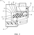
- Fig. 5 is a cross-section view illustrating the first-half 30 with the cable-clamp 24 in a pre-stage position 54.
- the pair of opposed inclined-surfaces 26 are inclined relative to a longitudinal-axis 56 of the cable 14, as indicated by the dashed-line extending from the inclined-surface 26, and are oriented generally parallel to the inclined-surfaces 26.
- the cable-clamps 24 include inclined-ramps 58 configured to engage the inclined-surfaces 26.
- the cable-clamps 24 are releasably locked in the pre-stage position 54 by locking-features 60 that project from a top-surface 62 of the inclined-ramps 58.
- the locking-features 60 are disposed within apertures 64 defined by arms 66 overlaying the inclined-surfaces 26 that project from a back-side 68 of the retainer 12.
- the apertures 64 are further configured to retain the locking-features 60 when the cable-clamps 24 are moved from the pre-stage position 54 to a clamped-position 70, as will be described below.
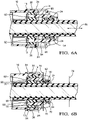
- Figs. 6A-6B illustrate a progression of attaching the retainer 12 to the connector-body 16.
- the retainer 12 is configured to be moved along the cable 14 toward the connector-body 16 in the direction parallel to the longitudinal-axis 56.
- Fig. 6A illustrates the retainer 12 with the cable-clamps 24 in the pre-stage position 54 and the first-locking-tabs 34 on the retainer 12 are not yet engaged with the first-locking-ramps 38 on the connector-body 16.
- a leading-edge 72 see Fig.
- the inclined-ramps 24 preferably engage the cable 14 for a length of between 75% to 85% of an outer-diameter 78 dimension of the cable 14.
- the cable-clamps 24 define a contact-surface 80 in direct contact with the cable 14.
- the contact-surface 80 defines a plurality of grooves 82 extending below the contact-surface 80, whereby a portion of the outer-jacket 18 of the cable 14 is disposed within the plurality of grooves 82 when the cable-clamps 24 impart the radial-force 76, as illustrated in Fig 6B .
- the cable-clamps 24 further include a face 84 extending perpendicular to the longitudinal-axis 56 of the cable 14 that is configured to engage the cable-seal 13 when the retainer 12 is attached to the connector-body 16.
- the face 84 maintains a compressive-force on the cable-seal 13 that retains the cable-seal 13 in the designed position to inhibit contamination from entering the connector-body 16.
- Figs. 7A illustrates the back-side 68 of the retainer 12 that is assembled over a pair of cables 14.
- the retainer 12 further includes a clip-lock 86 disposed between the plurality of cables 14.
- Fig. 7B illustrates an exploded-view of the retainer 12 of Fig. 7A isolated from the cable assembly 10.
- the clip-lock 86 includes a first-clip 86A located on the first-half 30 of the retainer 12 and a corresponding second-clip 86B located on the opposed second-half 32 of the retainer 12.
- the first-clip 86A and the corresponding second-clip 86B are configured to engage one another when the retainer 12 is installed onto the cable 14 and enables the radial-force 76 to be consistently applied about the cable 14 where a plurality of cables 14 are present.
- the retainer 12 may include a plurality of terminal position assurance posts 88 (TPA-posts 88) configured to engage an inner-ferrule 90 disposed within the connector-body 16 when the retainer 12 is attached to the connector-body 16, as illustrated in Figs. 6A-6B .
- the plurality of TPA-posts 88 extend from the back-side 68 of the retainer 12 and are aligned parallel to the longitudinal-axis 56 of the cable 14.
- the plurality of TPA-posts 88 pass through passages 92 formed in the cable-seal 13 and contact the inner-ferrule 90 and apply an axial-force (not shown) to ensure the inner-ferrule 90 is properly seated.
- a cable assembly 10 is provided.
- the cable assembly 10 is an improvement over other cable assemblies because the cable assembly 10 includes a two-piece retainer 12 with cable-clamps 24 that is configured to be installed onto the cable 14 after the cable 14 is assembled into the connector-body 16.
- the cable-clamps 24 provide strain relief for the cable 14, and especially for a large-diameter cable 14 (e.g. greater than 5 mm) typically used in high-voltage applications.
- first, second, upper, lower, etc. does not denote any order of importance, location, or orientation, but rather the terms first, second, etc. are used to distinguish one element from another.
- use of the terms a, an, etc. do not denote a limitation of quantity, but rather denote the presence of at least one of the referenced items.
Landscapes
- Engineering & Computer Science (AREA)
- Manufacturing & Machinery (AREA)
- Microelectronics & Electronic Packaging (AREA)
- Details Of Connecting Devices For Male And Female Coupling (AREA)
- Connector Housings Or Holding Contact Members (AREA)
Claims (14)
- Kabelanordnung (10), umfassend:ein Kabel (14);einen Verbinderkörper (16), der an dem Kabel (14) angebracht ist;eine Kabeldichtung (13), die innerhalb des Verbinderkörpers (16) angeordnet ist und das Kabel (14) umgibt; undeinen Halter (12) in direktem Kontakt mit dem Kabel (14), dem Verbinderkörper (16) und der Kabeldichtung (13), wobei der Halter (12) dazu konfiguriert ist, die Kabeldichtung (13) innerhalb des Verbinderkörpers (16) zu halten, und ferner dazu konfiguriert ist, an dem Verbinderkörper (16) angebracht zu werden, wobei der Halter (12) eine erste Hälfte (30) und eine mit der ersten Hälfte (30) identische gegenüberliegende zweite Hälfte (32) beinhaltet, wobei die erste Hälfte (30) dazu konfiguriert ist, mit der gegenüberliegenden zweiten Hälfte (32) zusammenzupassen, wobei die erste Hälfte (30) und die gegenüberliegende zweite Hälfte (32) jeweils Kabelklemmen (24) enthalten, wobei die Kabelklemmen (24) in Längsrichtung verschiebbar an einem Paar gegenüberliegenden schrägen Oberflächen (26) montiert sind, das sich an einer inneren Oberfläche (28) des Halters (12) befindet und relativ zu einer Längsachse (56) des Kabels (14) schräg ist, wobei die Kabelklemmen (24) schräge Rampen (58) beinhalten, die dazu konfiguriert sind, in die schrägen Oberflächen (26) einzugreifen, und wobei die schrägen Rampen (58) dazu konfiguriert sind, sich entlang der schrägen Oberflächen (26) zu bewegen, wodurch bewirkt wird, dass die Kabelklemmen (24) eine Radialkraft (76) normal zu dem Kabel (14) ausüben, wenn der Halter (12) an dem Verbinderkörper (16) angebracht ist, wobei die Kabelklemmen (24) dazu konfiguriert sind, aus einer Vorstufenposition (54) in eine Klemmposition (70) bewegt zu werden, wenn der Halter (12) an dem Verbinderkörper (16) angebracht ist,wobei die Kabelklemmen (24) durch Verriegelungsmerkmale (60), die von einer oberen Oberfläche (62) der schrägen Rampen (58) vorstehen, lösbar in der Vorstufenposition (54) verriegelt sind, wobei die Verriegelungsmerkmale (60) innerhalb von Öffnungen (64) angeordnet sind, die durch Arme (66) definiert sind, die die schrägen Oberflächen (26) überlagern, wobei die Arme (66) von einer Rückseite (68) des Halters (12) vorstehen, wobei die Öffnungen (64) dazu konfiguriert sind, die Verriegelungsmerkmale (60) zu halten, wenn die Kabelklemmen (24) aus der Vorstufenposition (54) in die Klemmposition (70) bewegt werden.
- Kabelanordnung (10) nach Anspruch 1, wobei der Halter (12) dazu konfiguriert ist, entlang des Kabels (14) bewegt zu werden.
- Kabelanordnung (10) nach Anspruch 1 oder 2, wobei die schrägen Rampen (58) im Allgemeinen parallel zu den schrägen Oberflächen (26) ausgerichtet sind.
- Kabelanordnung (10) nach einem der vorhergehenden Ansprüche, wobei eine Vorderkante (72) der schrägen Rampen (58) in eine Hinterkante (74) des Verbinderkörpers (16) eingreift, wenn der Halter (12) an dem Verbinderkörper (16) angebracht ist.
- Kabelanordnung (10) nach einem der vorhergehenden Ansprüche, wobei die Kabelklemmen (24) ferner eine Fläche (84) beinhalten, die sich senkrecht zu der Längsachse (56) des Kabels (14) erstreckt, und wobei die Fläche (84) dazu konfiguriert ist, in die Kabeldichtung (13) einzugreifen, wenn der Halter (12) an dem Verbinderkörper (16) angebracht ist.
- Kabelanordnung (10) nach Anspruch 1, wobei die erste Hälfte (30) und die gegenüberliegende zweite Hälfte (32) mindestens eine erste Verriegelungslasche (34) an einer Unterseite (36) beinhalten, wobei die mindestens eine erste Verriegelungslasche (34) dazu konfiguriert ist, in eine erste Verriegelungsrampe (38) an einer äußeren Oberfläche (40) des Verbinderkörpers (16) einzugreifen.
- Kabelanordnung (10) nach Anspruch 1, wobei die erste Hälfte (30) und die gegenüberliegende zweite Hälfte (32) mindestens eine zweite Verriegelungslasche (42) und mindestens eine zweite Verriegelungsrampe (44) an sowohl einer ersten Seite (46) als auch einer zweiten Seite (48) gegenüber der ersten Seite einer äußeren Oberfläche (40) der ersten Hälfte (30) und der gegenüberliegenden zweiten Hälfte (32) beinhalten.
- Kabelanordnung (10) nach Anspruch 7, wobei sich die zweite Verriegelungslasche (42) in einer Vorwärtsposition (52) befindet und sich die zweite Verriegelungsrampe (44) in der Vorwärtsposition (52) befindet.
- Kabelanordnung (10) nach einem der vorhergehenden Ansprüche, wobei die Kabelklemmen (24) eine Kontaktoberfläche (80) definieren, wobei die Kontaktoberfläche (80) in direktem Kontakt mit dem Kabel (14) steht und wobei die Kontaktoberfläche (80) eine Vielzahl von Nuten (82) definiert, die sich unterhalb der Kontaktoberfläche (80) erstreckt, wodurch ein Abschnitt eines Außenmantels (18) des Kabels (14) innerhalb der Vielzahl von Nuten (82) angeordnet ist, wenn die Kabelklemmen (24) die Radialkraft (76) normal zu dem Kabel (14) ausüben.
- Kabelanordnung (10) nach einem der vorhergehenden Ansprüche, wobei die Kabelanordnung (10) ferner eine Vielzahl von Kabeln (14) beinhaltet und der Halter (12) ferner eine zwischen der Vielzahl von Kabeln (14) angeordnete Bügelverriegelung (86) beinhaltet.
- Kabelanordnung (10) nach Anspruch 10, wobei die Bügelverriegelung (86) einen ersten Bügel (86A), der sich an der ersten Hälfte (30) des Halters (12) befindet, und einen entsprechenden zweiten Bügel (86B), der sich an der gegenüberliegenden zweiten Hälfte (32) des Halters (12) befindet, umfasst, und wobei der erste Bügel (86A) und der entsprechende zweite Bügel (86B) dazu konfiguriert sind, ineinander einzugreifen, wenn der Halter (12) an dem Kabel (14) installiert ist.
- Kabelanordnung (10) nach Anspruch 1, wobei der Halter (12) eine Vielzahl von Polklemmen (88) zur Sicherung der Klemmenposition (TPA) umfasst, die dazu konfiguriert ist, in eine innere Aderendhülse (90) einzugreifen, die innerhalb des Verbinderkörpers (16) angeordnet ist, wobei sich die Vielzahl von TPA-Polklemmen (88) von einer Rückseite (68) des Halters (12) parallel zu der Längsachse (56) des Kabels (14) erstreckt.
- Kabelanordnung (10) nach Anspruch 13, wobei die Vielzahl von TPA-Polklemmen (88) durch in der Kabeldichtung (13) ausgebildete Durchlässe (92) verläuft.
- Kabelanordnung (10) nach einem der vorhergehenden Ansprüche, wobei die Kabelklemmen (24) in das Kabel (14) entlang einer Länge des Kabels (14) eingreifen, die eine Längenabmessung in einem Bereich von 75 % bis 85 % einer Abmessung eines Außendurchmessers (78) des Kabels (14) aufweist.
Applications Claiming Priority (3)
| Application Number | Priority Date | Filing Date | Title |
|---|---|---|---|
| US201762539656P | 2017-08-01 | 2017-08-01 | |
| US15/867,277 US10573988B2 (en) | 2017-08-01 | 2018-01-10 | Cable assembly with strain relief |
| PCT/US2018/042791 WO2019027682A1 (en) | 2017-08-01 | 2018-07-19 | CABLE ASSEMBLY WITH CONSTRAINTS REDUCTION |
Publications (3)
| Publication Number | Publication Date |
|---|---|
| EP3662544A1 EP3662544A1 (de) | 2020-06-10 |
| EP3662544A4 EP3662544A4 (de) | 2021-05-05 |
| EP3662544B1 true EP3662544B1 (de) | 2022-11-02 |
Family
ID=74882442
Family Applications (1)
| Application Number | Title | Priority Date | Filing Date |
|---|---|---|---|
| EP18840193.9A Active EP3662544B1 (de) | 2017-08-01 | 2018-07-19 | Kabelanordnung mit zugentlastung |
Country Status (4)
| Country | Link |
|---|---|
| US (2) | US10573988B2 (de) |
| EP (1) | EP3662544B1 (de) |
| CN (1) | CN110998983B (de) |
| WO (1) | WO2019027682A1 (de) |
Cited By (1)
| Publication number | Priority date | Publication date | Assignee | Title |
|---|---|---|---|---|
| DE102022126544A1 (de) * | 2022-10-12 | 2024-04-18 | Amphenol-Tuchel Electronics Gesellschaft mit beschränkter Haftung | Kabelklemmung |
Families Citing this family (28)
| Publication number | Priority date | Publication date | Assignee | Title |
|---|---|---|---|---|
| WO2016069570A2 (en) | 2014-10-27 | 2016-05-06 | Fci Asia Pte. Ltd | Circular power connectors |
| US10573988B2 (en) * | 2017-08-01 | 2020-02-25 | Delphi Technologies, Llc | Cable assembly with strain relief |
| JP6735313B2 (ja) * | 2018-05-22 | 2020-08-05 | 矢崎総業株式会社 | 閉塞体保持構造及びコネクタ付き電線 |
| US10923863B2 (en) * | 2018-12-04 | 2021-02-16 | J.S.T. Corporation | High voltage connector and method for assembling thereof |
| JP6999246B2 (ja) * | 2019-05-27 | 2022-01-18 | 矢崎総業株式会社 | コネクタ、及び、ワイヤハーネス |
| WO2021045908A1 (en) * | 2019-09-06 | 2021-03-11 | Corning Research & Development Corporation | Cable seal and strain relief assembly |
| JP7392349B2 (ja) * | 2019-09-24 | 2023-12-06 | 住友電装株式会社 | 通信ケーブル |
| US11735858B2 (en) | 2020-07-14 | 2023-08-22 | J.S.T. Corporation | Elastomer seal spring |
| JP2022064366A (ja) * | 2020-10-14 | 2022-04-26 | 住友電装株式会社 | コネクタ |
| EP3989371B1 (de) * | 2020-10-20 | 2024-08-28 | Aptiv Technologies Limited | Verbinderanordnung mit zugentlastungsvorrichtung in zwei teilen |
| CN114696146B (zh) * | 2020-12-30 | 2025-05-13 | 安波福中央电气(上海)有限公司 | 电气连接器 |
| JP7447857B2 (ja) * | 2021-03-31 | 2024-03-12 | 住友電装株式会社 | コネクタ及びワイヤハーネス |
| JP7591454B2 (ja) * | 2021-04-01 | 2024-11-28 | ヒロセ電機株式会社 | ケーブルコネクタ |
| CN214754556U (zh) * | 2021-05-09 | 2021-11-16 | 东莞市万旅电器有限公司 | 一种插座结构 |
| US12525755B2 (en) | 2021-07-19 | 2026-01-13 | Fci Usa Llc | Power connector for compact electronic systems |
| JP7387242B2 (ja) * | 2021-07-21 | 2023-11-28 | 矢崎総業株式会社 | ワイヤハーネス |
| US12355183B2 (en) * | 2021-08-31 | 2025-07-08 | Rivian Ip Holdings, Llc | Cable protection structures |
| US12444879B2 (en) | 2021-12-17 | 2025-10-14 | Aptiv Technologies AG | Strain relief device for electrical connectors |
| JP2025503254A (ja) * | 2022-01-30 | 2025-01-30 | アイディール インダストリーズ,インク. | 高い侵入保護機能を有する電気コネクタ |
| JP1730745S (ja) * | 2022-05-20 | 2022-11-28 | コネクタ | |
| JP1730746S (ja) * | 2022-05-20 | 2022-11-28 | コネクタ | |
| US20240030694A1 (en) * | 2022-07-21 | 2024-01-25 | Te Connectivity Solutions Gmbh | Cable Inlet Pass-Through Strain Relief Guide |
| CN117712752A (zh) | 2022-09-13 | 2024-03-15 | 李尔公司 | 用于电通路的帽组件 |
| CN117712753A (zh) | 2022-09-13 | 2024-03-15 | 李尔公司 | 用于电通路的壳体 |
| CN117712732A (zh) * | 2022-09-13 | 2024-03-15 | 李尔公司 | 用于电通路的接触组件 |
| JP2024064432A (ja) * | 2022-10-28 | 2024-05-14 | ヒロセ電機株式会社 | 電気コネクタ、及び電気コネクタ組立体 |
| EP4468530A1 (de) | 2023-05-26 | 2024-11-27 | Aptiv Technologies AG | Abgedichteter verbinder mit einem in das gehäuse integrierten halter |
| EP4622017A1 (de) | 2024-03-21 | 2025-09-24 | Rosenberger Hochfrequenztechnik GmbH & Co. KG | Abschlussbaugruppe einer kabelsteckverbinderanordnung, kabelsteckverbinderanordnung und verfahren zur montage einer kabelsteckverbinderanordnung |
Family Cites Families (55)
| Publication number | Priority date | Publication date | Assignee | Title |
|---|---|---|---|---|
| US2816672A (en) * | 1956-08-15 | 1957-12-17 | Rigo R Facchini | Triple adjustable boat-supporting bracket |
| US3272913A (en) * | 1964-03-18 | 1966-09-13 | Thomas & Betts Co Inc | Two-wire socket insulator |
| US4108527A (en) * | 1977-06-23 | 1978-08-22 | Amp Incorporated | Strain relief assembly |
| US4138185A (en) * | 1977-10-04 | 1979-02-06 | Harvey Hubbell, Incorporated | Electric cord clamp device |
| JPS5882780U (ja) * | 1981-11-30 | 1983-06-04 | 住友電装株式会社 | 防水コネクタ |
| US4963104A (en) * | 1989-05-01 | 1990-10-16 | Spark Innovations, Inc. | Shielded connector assembly |
| US5211576A (en) * | 1991-09-27 | 1993-05-18 | Glenair, Inc. | Strain relief cable clamp |
| US5207598A (en) | 1992-02-24 | 1993-05-04 | Molex Incorporated | Edge card connector |
| BR9403559A (pt) | 1994-09-14 | 1996-09-03 | Amp Do Brasil Conectores Eletr | Conjunto de capa de proteçao para ser utilizado com pelo menos um condutor elétrico conectado a um conector elétrico |
| US5591046A (en) * | 1995-06-07 | 1997-01-07 | Hubbell Incorporated | Electrical cord clamp |
| US5588870A (en) * | 1995-06-07 | 1996-12-31 | Hubbell Incorporated | Electrical cord clamp |
| US5683273A (en) * | 1996-07-24 | 1997-11-04 | The Whitaker Corporation | Mechanical splice connector for cable |
| DE19712810A1 (de) * | 1997-03-26 | 1998-10-01 | Whitaker Corp | Kabelstecker für ein Kabel mit einem Beidraht |
| DE19839114A1 (de) | 1998-08-27 | 2000-03-02 | Delphi Automotive Systems Gmbh | Elektrischer Anschluß für einen flachen elektrischen Leiter und ein Verbindungsverfahren |
| TW446208U (en) | 1999-12-17 | 2001-07-11 | Hon Hai Prec Ind Co Ltd | Stack-type electrical connector |
| US6485337B2 (en) | 2000-08-30 | 2002-11-26 | Delphi Technologies, Inc. | Electrical connector |
| US6692316B2 (en) | 2002-04-16 | 2004-02-17 | Delphi Technologies, Inc. | High current terminal blade type sealed connection system |
| US6945826B2 (en) | 2003-05-02 | 2005-09-20 | Charles Michael Wise | Method and apparatus for preventing electric shocking |
| US6948976B2 (en) * | 2004-03-01 | 2005-09-27 | Andrew Corporation | Cable and apparatus interface environmental seal |
| DE102005040952A1 (de) * | 2005-08-30 | 2007-03-08 | Kostal Kontakt Systeme Gmbh | Elektrischer Nullkraftsteckverbinder |
| JP2007103120A (ja) | 2005-10-03 | 2007-04-19 | Sumitomo Wiring Syst Ltd | コネクタ |
| TWI330236B (en) * | 2006-01-30 | 2010-09-11 | Smc Corp | Electromagnetic valve |
| JP4839989B2 (ja) * | 2006-07-04 | 2011-12-21 | 住友電装株式会社 | コネクタ |
| US7413466B2 (en) | 2006-08-29 | 2008-08-19 | Adc Telecommunications, Inc. | Threaded connector and patch cord having a threaded connector |
| US7465192B2 (en) | 2006-09-11 | 2008-12-16 | J.S.T. Corporation | In-line sealed electrical connector apparatus |
| WO2009058270A2 (en) | 2007-10-31 | 2009-05-07 | Corning Gilbert Inc. | Coaxial connector with telescoping center conductor mechanism |
| US8109789B2 (en) | 2008-12-12 | 2012-02-07 | Tyco Electronics Corporation | Connector assembly with strain relief |
| US7632148B1 (en) | 2009-02-18 | 2009-12-15 | J.S.T. Corporation | Sealed and grounded electrical connector and sealed and grounded electrical connector assembly |
| JP5618985B2 (ja) * | 2009-03-24 | 2014-11-05 | 矢崎総業株式会社 | 防水コネクタ |
| JP5375440B2 (ja) | 2009-08-26 | 2013-12-25 | 住友電装株式会社 | 雄型コネクタ及びコネクタ装置 |
| CN201541002U (zh) | 2009-12-03 | 2010-08-04 | 四川华丰企业集团有限公司 | 电源连接器基座与金属端子锁紧结构 |
| CN201667450U (zh) * | 2010-03-18 | 2010-12-08 | 欧姆龙(上海)有限公司 | 线缆紧固装置 |
| US8545275B2 (en) | 2010-04-07 | 2013-10-01 | Alltop Electronics (Suzhou) Ltd. | Electrical connector with touch-safety contact structures |
| US20110312211A1 (en) | 2010-06-22 | 2011-12-22 | John Mezzalingua Associates, Inc. | Strain relief accessory for coaxial cable connector |
| US8454385B2 (en) | 2010-06-22 | 2013-06-04 | John Mezzalingua Associates, LLC | Coaxial cable connector with strain relief clamp |
| US8288667B2 (en) | 2010-08-11 | 2012-10-16 | Avc Industrial Corp. | Double-packing cable and flexible conduit gland |
| EP2418742B1 (de) | 2010-08-13 | 2016-04-27 | TE Connectivity Germany GmbH | Fingerschutz für 90°-Verbinder |
| US8419486B2 (en) | 2010-12-17 | 2013-04-16 | Tyco Electronics Corporation | Receptacle terminal with a contact spring |
| DE102012209298B4 (de) | 2012-06-01 | 2017-10-05 | Te Connectivity Germany Gmbh | Elektrischer Steckverbinder, Steckverbinderanordnung sowie Verfahren zum Montieren des Steckverbinders |
| CN103545627B (zh) | 2012-07-17 | 2015-09-09 | 凡甲电子(苏州)有限公司 | 电源连接器 |
| JP2014154359A (ja) * | 2013-02-08 | 2014-08-25 | Yazaki Corp | コネクタ |
| US9153889B2 (en) | 2013-04-09 | 2015-10-06 | Delphi Technologies, Inc. | Electrical connector system connectable in a straight or right angle configuration |
| EP2816672B1 (de) * | 2013-06-21 | 2016-11-16 | Delphi Technologies, Inc. | Zugentlastungssystem für elektrische Verbinderanordnung |
| JP6065228B2 (ja) | 2013-11-27 | 2017-01-25 | 住友電装株式会社 | コネクタ |
| DE102013113878B4 (de) * | 2013-12-11 | 2020-03-26 | HARTING Electronics GmbH | Steckverbinder mit Einzeladerabdichtung |
| DE102014008343A1 (de) * | 2014-06-04 | 2015-12-17 | Kostal Kontakt Systeme Gmbh | Elektrisches Gerät |
| DE102014109043B4 (de) * | 2014-06-27 | 2016-06-16 | Phoenix Contact Gmbh & Co. Kg | Kabelanschlussbauteil |
| CN204167595U (zh) * | 2014-11-08 | 2015-02-18 | 浙江科瑞普电气有限公司 | 一种工业插座 |
| US9954337B2 (en) * | 2014-12-22 | 2018-04-24 | Selvin Kao | Electrical plugs with integrated strain relief and method of manufacture |
| CN204424548U (zh) * | 2014-12-31 | 2015-06-24 | 德尔福中央电气(上海)有限公司 | 一种连接器防水圈挡块 |
| CA2925184A1 (en) * | 2016-03-29 | 2017-09-29 | Ipex Technologies Inc. | Grommet for a cable connector and a strain relief cable fitting |
| CN205846336U (zh) * | 2016-07-26 | 2016-12-28 | 上海三竹机电设备有限公司 | 信号连接器出线防水机构 |
| JP6467383B2 (ja) * | 2016-08-10 | 2019-02-13 | 矢崎総業株式会社 | コネクタ |
| CN106299808B (zh) | 2016-09-26 | 2018-10-12 | 欧品电子(昆山)有限公司 | 铜排连接器及端子组件 |
| US10573988B2 (en) * | 2017-08-01 | 2020-02-25 | Delphi Technologies, Llc | Cable assembly with strain relief |
-
2018
- 2018-01-10 US US15/867,277 patent/US10573988B2/en active Active
- 2018-07-19 EP EP18840193.9A patent/EP3662544B1/de active Active
- 2018-07-19 WO PCT/US2018/042791 patent/WO2019027682A1/en not_active Ceased
- 2018-07-19 CN CN201880050282.2A patent/CN110998983B/zh active Active
-
2019
- 2019-12-12 US US16/711,907 patent/US10897099B2/en active Active
Cited By (1)
| Publication number | Priority date | Publication date | Assignee | Title |
|---|---|---|---|---|
| DE102022126544A1 (de) * | 2022-10-12 | 2024-04-18 | Amphenol-Tuchel Electronics Gesellschaft mit beschränkter Haftung | Kabelklemmung |
Also Published As
| Publication number | Publication date |
|---|---|
| CN110998983B (zh) | 2021-04-20 |
| US10573988B2 (en) | 2020-02-25 |
| US10897099B2 (en) | 2021-01-19 |
| US20190044277A1 (en) | 2019-02-07 |
| EP3662544A1 (de) | 2020-06-10 |
| CN110998983A (zh) | 2020-04-10 |
| EP3662544A4 (de) | 2021-05-05 |
| WO2019027682A1 (en) | 2019-02-07 |
| US20200119480A1 (en) | 2020-04-16 |
Similar Documents
| Publication | Publication Date | Title |
|---|---|---|
| EP3662544B1 (de) | Kabelanordnung mit zugentlastung | |
| US10574001B2 (en) | High power electrical connector | |
| CN103843102B (zh) | 同轴熔断器保持组件 | |
| US7264506B2 (en) | Terminal-movable connector | |
| US20160329651A1 (en) | Live portion protection structure and connector | |
| EP2020701A1 (de) | Kabelabschluss | |
| EP3706252A1 (de) | Verbinderanordnung und verfahren zu ihrer montage | |
| US9768548B2 (en) | Multicore cable and method for manufacturing the same | |
| EP2729995B1 (de) | Buchsenstecker für raue umgebungsbedingungen | |
| US9928939B1 (en) | Device and method for splicing shielded wire cables | |
| JP2009252682A (ja) | コネクタ | |
| CA2975733C (en) | Fiber optic cable external shield connector | |
| EP3619782A1 (de) | Verspleisstes abgeschirmtes drahtkabel und herstellungsverfahren dafür | |
| US9906003B1 (en) | Device and method for splicing shielded wire cables | |
| US8263865B2 (en) | Wire connection unit | |
| US20180294629A1 (en) | Device and method for splicing shielded wire cables | |
| KR100800790B1 (ko) | 하우징 조립체 및 이를 구비하는 실드커넥터 | |
| CN104682090B (zh) | 具有线保持管的电连接器 | |
| WO2017061249A1 (ja) | コネクタ | |
| JP4278846B2 (ja) | 機器接続用シールドコネクタ | |
| KR100882047B1 (ko) | 접속이 용이한 하우징 조립체, 이를 구비하는 실드커넥터,및 실드커넥터 세트 | |
| CN119923775A (zh) | 配线部件 | |
| US20250157691A1 (en) | Wire harness arrangement structure | |
| EP3509165A1 (de) | Wasserdichter stecker | |
| KR100800788B1 (ko) | 실드쉘 접속수단 및 이를 구비한 실드커넥터 |
Legal Events
| Date | Code | Title | Description |
|---|---|---|---|
| STAA | Information on the status of an ep patent application or granted ep patent |
Free format text: STATUS: THE INTERNATIONAL PUBLICATION HAS BEEN MADE |
|
| PUAI | Public reference made under article 153(3) epc to a published international application that has entered the european phase |
Free format text: ORIGINAL CODE: 0009012 |
|
| STAA | Information on the status of an ep patent application or granted ep patent |
Free format text: STATUS: REQUEST FOR EXAMINATION WAS MADE |
|
| 17P | Request for examination filed |
Effective date: 20200228 |
|
| AK | Designated contracting states |
Kind code of ref document: A1 Designated state(s): AL AT BE BG CH CY CZ DE DK EE ES FI FR GB GR HR HU IE IS IT LI LT LU LV MC MK MT NL NO PL PT RO RS SE SI SK SM TR |
|
| AX | Request for extension of the european patent |
Extension state: BA ME |
|
| DAV | Request for validation of the european patent (deleted) | ||
| DAX | Request for extension of the european patent (deleted) | ||
| A4 | Supplementary search report drawn up and despatched |
Effective date: 20210406 |
|
| RIC1 | Information provided on ipc code assigned before grant |
Ipc: H01R 13/58 20060101AFI20210329BHEP Ipc: H01R 13/506 20060101ALI20210329BHEP Ipc: H01R 13/52 20060101ALI20210329BHEP Ipc: H01R 103/00 20060101ALN20210329BHEP Ipc: H01R 13/436 20060101ALN20210329BHEP |
|
| RAP1 | Party data changed (applicant data changed or rights of an application transferred) |
Owner name: APTIV TECHNOLOGIES LIMITED |
|
| GRAP | Despatch of communication of intention to grant a patent |
Free format text: ORIGINAL CODE: EPIDOSNIGR1 |
|
| STAA | Information on the status of an ep patent application or granted ep patent |
Free format text: STATUS: GRANT OF PATENT IS INTENDED |
|
| RIC1 | Information provided on ipc code assigned before grant |
Ipc: H01R 13/436 20060101ALN20220621BHEP Ipc: H01R 103/00 20060101ALN20220621BHEP Ipc: H01R 13/52 20060101ALI20220621BHEP Ipc: H01R 13/506 20060101ALI20220621BHEP Ipc: H01R 13/58 20060101AFI20220621BHEP |
|
| RIC1 | Information provided on ipc code assigned before grant |
Ipc: H01R 13/436 20060101ALN20220630BHEP Ipc: H01R 103/00 20060101ALN20220630BHEP Ipc: H01R 13/52 20060101ALI20220630BHEP Ipc: H01R 13/506 20060101ALI20220630BHEP Ipc: H01R 13/58 20060101AFI20220630BHEP |
|
| INTG | Intention to grant announced |
Effective date: 20220713 |
|
| GRAS | Grant fee paid |
Free format text: ORIGINAL CODE: EPIDOSNIGR3 |
|
| GRAA | (expected) grant |
Free format text: ORIGINAL CODE: 0009210 |
|
| STAA | Information on the status of an ep patent application or granted ep patent |
Free format text: STATUS: THE PATENT HAS BEEN GRANTED |
|
| AK | Designated contracting states |
Kind code of ref document: B1 Designated state(s): AL AT BE BG CH CY CZ DE DK EE ES FI FR GB GR HR HU IE IS IT LI LT LU LV MC MK MT NL NO PL PT RO RS SE SI SK SM TR |
|
| REG | Reference to a national code |
Ref country code: GB Ref legal event code: FG4D |
|
| REG | Reference to a national code |
Ref country code: CH Ref legal event code: EP Ref country code: AT Ref legal event code: REF Ref document number: 1529449 Country of ref document: AT Kind code of ref document: T Effective date: 20221115 |
|
| REG | Reference to a national code |
Ref country code: DE Ref legal event code: R096 Ref document number: 602018042653 Country of ref document: DE |
|
| REG | Reference to a national code |
Ref country code: IE Ref legal event code: FG4D |
|
| REG | Reference to a national code |
Ref country code: LT Ref legal event code: MG9D |
|
| REG | Reference to a national code |
Ref country code: NL Ref legal event code: MP Effective date: 20221102 |
|
| RAP4 | Party data changed (patent owner data changed or rights of a patent transferred) |
Owner name: APTIV TECHNOLOGIES LIMITED |
|
| REG | Reference to a national code |
Ref country code: AT Ref legal event code: MK05 Ref document number: 1529449 Country of ref document: AT Kind code of ref document: T Effective date: 20221102 |
|
| PG25 | Lapsed in a contracting state [announced via postgrant information from national office to epo] |
Ref country code: SE Free format text: LAPSE BECAUSE OF FAILURE TO SUBMIT A TRANSLATION OF THE DESCRIPTION OR TO PAY THE FEE WITHIN THE PRESCRIBED TIME-LIMIT Effective date: 20221102 Ref country code: PT Free format text: LAPSE BECAUSE OF FAILURE TO SUBMIT A TRANSLATION OF THE DESCRIPTION OR TO PAY THE FEE WITHIN THE PRESCRIBED TIME-LIMIT Effective date: 20230302 Ref country code: NO Free format text: LAPSE BECAUSE OF FAILURE TO SUBMIT A TRANSLATION OF THE DESCRIPTION OR TO PAY THE FEE WITHIN THE PRESCRIBED TIME-LIMIT Effective date: 20230202 Ref country code: LT Free format text: LAPSE BECAUSE OF FAILURE TO SUBMIT A TRANSLATION OF THE DESCRIPTION OR TO PAY THE FEE WITHIN THE PRESCRIBED TIME-LIMIT Effective date: 20221102 Ref country code: FI Free format text: LAPSE BECAUSE OF FAILURE TO SUBMIT A TRANSLATION OF THE DESCRIPTION OR TO PAY THE FEE WITHIN THE PRESCRIBED TIME-LIMIT Effective date: 20221102 Ref country code: ES Free format text: LAPSE BECAUSE OF FAILURE TO SUBMIT A TRANSLATION OF THE DESCRIPTION OR TO PAY THE FEE WITHIN THE PRESCRIBED TIME-LIMIT Effective date: 20221102 Ref country code: AT Free format text: LAPSE BECAUSE OF FAILURE TO SUBMIT A TRANSLATION OF THE DESCRIPTION OR TO PAY THE FEE WITHIN THE PRESCRIBED TIME-LIMIT Effective date: 20221102 |
|
| PG25 | Lapsed in a contracting state [announced via postgrant information from national office to epo] |
Ref country code: RS Free format text: LAPSE BECAUSE OF FAILURE TO SUBMIT A TRANSLATION OF THE DESCRIPTION OR TO PAY THE FEE WITHIN THE PRESCRIBED TIME-LIMIT Effective date: 20221102 Ref country code: PL Free format text: LAPSE BECAUSE OF FAILURE TO SUBMIT A TRANSLATION OF THE DESCRIPTION OR TO PAY THE FEE WITHIN THE PRESCRIBED TIME-LIMIT Effective date: 20221102 Ref country code: LV Free format text: LAPSE BECAUSE OF FAILURE TO SUBMIT A TRANSLATION OF THE DESCRIPTION OR TO PAY THE FEE WITHIN THE PRESCRIBED TIME-LIMIT Effective date: 20221102 Ref country code: IS Free format text: LAPSE BECAUSE OF FAILURE TO SUBMIT A TRANSLATION OF THE DESCRIPTION OR TO PAY THE FEE WITHIN THE PRESCRIBED TIME-LIMIT Effective date: 20230302 Ref country code: HR Free format text: LAPSE BECAUSE OF FAILURE TO SUBMIT A TRANSLATION OF THE DESCRIPTION OR TO PAY THE FEE WITHIN THE PRESCRIBED TIME-LIMIT Effective date: 20221102 Ref country code: GR Free format text: LAPSE BECAUSE OF FAILURE TO SUBMIT A TRANSLATION OF THE DESCRIPTION OR TO PAY THE FEE WITHIN THE PRESCRIBED TIME-LIMIT Effective date: 20230203 |
|
| P01 | Opt-out of the competence of the unified patent court (upc) registered |
Effective date: 20230424 |
|
| PG25 | Lapsed in a contracting state [announced via postgrant information from national office to epo] |
Ref country code: NL Free format text: LAPSE BECAUSE OF FAILURE TO SUBMIT A TRANSLATION OF THE DESCRIPTION OR TO PAY THE FEE WITHIN THE PRESCRIBED TIME-LIMIT Effective date: 20221102 |
|
| PG25 | Lapsed in a contracting state [announced via postgrant information from national office to epo] |
Ref country code: SM Free format text: LAPSE BECAUSE OF FAILURE TO SUBMIT A TRANSLATION OF THE DESCRIPTION OR TO PAY THE FEE WITHIN THE PRESCRIBED TIME-LIMIT Effective date: 20221102 Ref country code: RO Free format text: LAPSE BECAUSE OF FAILURE TO SUBMIT A TRANSLATION OF THE DESCRIPTION OR TO PAY THE FEE WITHIN THE PRESCRIBED TIME-LIMIT Effective date: 20221102 Ref country code: EE Free format text: LAPSE BECAUSE OF FAILURE TO SUBMIT A TRANSLATION OF THE DESCRIPTION OR TO PAY THE FEE WITHIN THE PRESCRIBED TIME-LIMIT Effective date: 20221102 Ref country code: DK Free format text: LAPSE BECAUSE OF FAILURE TO SUBMIT A TRANSLATION OF THE DESCRIPTION OR TO PAY THE FEE WITHIN THE PRESCRIBED TIME-LIMIT Effective date: 20221102 Ref country code: CZ Free format text: LAPSE BECAUSE OF FAILURE TO SUBMIT A TRANSLATION OF THE DESCRIPTION OR TO PAY THE FEE WITHIN THE PRESCRIBED TIME-LIMIT Effective date: 20221102 |
|
| REG | Reference to a national code |
Ref country code: DE Ref legal event code: R097 Ref document number: 602018042653 Country of ref document: DE |
|
| PG25 | Lapsed in a contracting state [announced via postgrant information from national office to epo] |
Ref country code: SK Free format text: LAPSE BECAUSE OF FAILURE TO SUBMIT A TRANSLATION OF THE DESCRIPTION OR TO PAY THE FEE WITHIN THE PRESCRIBED TIME-LIMIT Effective date: 20221102 Ref country code: AL Free format text: LAPSE BECAUSE OF FAILURE TO SUBMIT A TRANSLATION OF THE DESCRIPTION OR TO PAY THE FEE WITHIN THE PRESCRIBED TIME-LIMIT Effective date: 20221102 |
|
| PLBE | No opposition filed within time limit |
Free format text: ORIGINAL CODE: 0009261 |
|
| STAA | Information on the status of an ep patent application or granted ep patent |
Free format text: STATUS: NO OPPOSITION FILED WITHIN TIME LIMIT |
|
| 26N | No opposition filed |
Effective date: 20230803 |
|
| PG25 | Lapsed in a contracting state [announced via postgrant information from national office to epo] |
Ref country code: SI Free format text: LAPSE BECAUSE OF FAILURE TO SUBMIT A TRANSLATION OF THE DESCRIPTION OR TO PAY THE FEE WITHIN THE PRESCRIBED TIME-LIMIT Effective date: 20221102 |
|
| PG25 | Lapsed in a contracting state [announced via postgrant information from national office to epo] |
Ref country code: MC Free format text: LAPSE BECAUSE OF FAILURE TO SUBMIT A TRANSLATION OF THE DESCRIPTION OR TO PAY THE FEE WITHIN THE PRESCRIBED TIME-LIMIT Effective date: 20221102 |
|
| PG25 | Lapsed in a contracting state [announced via postgrant information from national office to epo] |
Ref country code: MC Free format text: LAPSE BECAUSE OF FAILURE TO SUBMIT A TRANSLATION OF THE DESCRIPTION OR TO PAY THE FEE WITHIN THE PRESCRIBED TIME-LIMIT Effective date: 20221102 |
|
| REG | Reference to a national code |
Ref country code: CH Ref legal event code: PL |
|
| REG | Reference to a national code |
Ref country code: BE Ref legal event code: MM Effective date: 20230731 |
|
| PG25 | Lapsed in a contracting state [announced via postgrant information from national office to epo] |
Ref country code: LU Free format text: LAPSE BECAUSE OF NON-PAYMENT OF DUE FEES Effective date: 20230719 |
|
| PG25 | Lapsed in a contracting state [announced via postgrant information from national office to epo] |
Ref country code: LU Free format text: LAPSE BECAUSE OF NON-PAYMENT OF DUE FEES Effective date: 20230719 |
|
| REG | Reference to a national code |
Ref country code: IE Ref legal event code: MM4A |
|
| PG25 | Lapsed in a contracting state [announced via postgrant information from national office to epo] |
Ref country code: CH Free format text: LAPSE BECAUSE OF NON-PAYMENT OF DUE FEES Effective date: 20230731 |
|
| PG25 | Lapsed in a contracting state [announced via postgrant information from national office to epo] |
Ref country code: IT Free format text: LAPSE BECAUSE OF FAILURE TO SUBMIT A TRANSLATION OF THE DESCRIPTION OR TO PAY THE FEE WITHIN THE PRESCRIBED TIME-LIMIT Effective date: 20221102 Ref country code: BE Free format text: LAPSE BECAUSE OF NON-PAYMENT OF DUE FEES Effective date: 20230731 |
|
| PG25 | Lapsed in a contracting state [announced via postgrant information from national office to epo] |
Ref country code: IE Free format text: LAPSE BECAUSE OF NON-PAYMENT OF DUE FEES Effective date: 20230719 |
|
| PG25 | Lapsed in a contracting state [announced via postgrant information from national office to epo] |
Ref country code: IE Free format text: LAPSE BECAUSE OF NON-PAYMENT OF DUE FEES Effective date: 20230719 |
|
| PG25 | Lapsed in a contracting state [announced via postgrant information from national office to epo] |
Ref country code: BG Free format text: LAPSE BECAUSE OF FAILURE TO SUBMIT A TRANSLATION OF THE DESCRIPTION OR TO PAY THE FEE WITHIN THE PRESCRIBED TIME-LIMIT Effective date: 20221102 |
|
| PG25 | Lapsed in a contracting state [announced via postgrant information from national office to epo] |
Ref country code: BG Free format text: LAPSE BECAUSE OF FAILURE TO SUBMIT A TRANSLATION OF THE DESCRIPTION OR TO PAY THE FEE WITHIN THE PRESCRIBED TIME-LIMIT Effective date: 20221102 |
|
| REG | Reference to a national code |
Ref country code: DE Ref legal event code: R081 Ref document number: 602018042653 Country of ref document: DE Owner name: APTIV TECHNOLOGIES AG, CH Free format text: FORMER OWNER: APTIV TECHNOLOGIES LIMITED, ST. MICHAEL, BB |
|
| PG25 | Lapsed in a contracting state [announced via postgrant information from national office to epo] |
Ref country code: CY Free format text: LAPSE BECAUSE OF FAILURE TO SUBMIT A TRANSLATION OF THE DESCRIPTION OR TO PAY THE FEE WITHIN THE PRESCRIBED TIME-LIMIT; INVALID AB INITIO Effective date: 20180719 |
|
| PG25 | Lapsed in a contracting state [announced via postgrant information from national office to epo] |
Ref country code: HU Free format text: LAPSE BECAUSE OF FAILURE TO SUBMIT A TRANSLATION OF THE DESCRIPTION OR TO PAY THE FEE WITHIN THE PRESCRIBED TIME-LIMIT; INVALID AB INITIO Effective date: 20180719 |
|
| PGFP | Annual fee paid to national office [announced via postgrant information from national office to epo] |
Ref country code: DE Payment date: 20250618 Year of fee payment: 8 |
|
| PGFP | Annual fee paid to national office [announced via postgrant information from national office to epo] |
Ref country code: GB Payment date: 20250703 Year of fee payment: 8 |
|
| PGFP | Annual fee paid to national office [announced via postgrant information from national office to epo] |
Ref country code: FR Payment date: 20250703 Year of fee payment: 8 |
|
| PG25 | Lapsed in a contracting state [announced via postgrant information from national office to epo] |
Ref country code: TR Free format text: LAPSE BECAUSE OF FAILURE TO SUBMIT A TRANSLATION OF THE DESCRIPTION OR TO PAY THE FEE WITHIN THE PRESCRIBED TIME-LIMIT Effective date: 20221102 |