EP3662735A1 - Machine de distribution pour épander un matériau d'épandage agricole granulaire et procédé pour distribuer un matériau d'épandage agricole granulaire - Google Patents
Machine de distribution pour épander un matériau d'épandage agricole granulaire et procédé pour distribuer un matériau d'épandage agricole granulaire Download PDFInfo
- Publication number
- EP3662735A1 EP3662735A1 EP19211736.4A EP19211736A EP3662735A1 EP 3662735 A1 EP3662735 A1 EP 3662735A1 EP 19211736 A EP19211736 A EP 19211736A EP 3662735 A1 EP3662735 A1 EP 3662735A1
- Authority
- EP
- European Patent Office
- Prior art keywords
- distribution
- linkage
- spreading
- spreading material
- distribution linkage
- Prior art date
- Legal status (The legal status is an assumption and is not a legal conclusion. Google has not performed a legal analysis and makes no representation as to the accuracy of the status listed.)
- Granted
Links
Images





Classifications
-
- A—HUMAN NECESSITIES
- A01—AGRICULTURE; FORESTRY; ANIMAL HUSBANDRY; HUNTING; TRAPPING; FISHING
- A01C—PLANTING; SOWING; FERTILISING
- A01C15/00—Fertiliser distributors
- A01C15/04—Fertiliser distributors using blowers
-
- A—HUMAN NECESSITIES
- A01—AGRICULTURE; FORESTRY; ANIMAL HUSBANDRY; HUNTING; TRAPPING; FISHING
- A01C—PLANTING; SOWING; FERTILISING
- A01C15/00—Fertiliser distributors
-
- A—HUMAN NECESSITIES
- A01—AGRICULTURE; FORESTRY; ANIMAL HUSBANDRY; HUNTING; TRAPPING; FISHING
- A01C—PLANTING; SOWING; FERTILISING
- A01C21/00—Methods of fertilising, sowing or planting
Definitions
- the invention relates to a distribution machine, in particular a pneumatic fertilizer spreader, for spreading granular agricultural spreading material.
- the invention also relates to a method for distributing granular agricultural material.
- fertilizer spreaders For the large-scale distribution of granular or granular agricultural spreading material, in particular for the distribution of agricultural fertilizer, essentially two different types of agricultural spreading machines known as fertilizer spreaders are known from the prior art.
- a first embodiment variant is represented by so-called disc spreaders or centrifugal spreaders, in which the spreading material is distributed by means of a disc-shaped centrifugal unit.
- the centrifugal unit is generally a horizontally or slightly inclined disc with, for example, 700min-1 to 1000min-1 rotating discs, on each disc of which a variable quantity of grit flowing through an outlet opening of a storage container falls and is attached to the discs Throwing bars is accelerated and flung away.
- the amount of spreading material is varied by enlarging or reducing the outlet opening of the storage container.
- the pattern created by the rotation of the discs usually corresponds to a circular ring sector.
- Such distribution machines usually have a simple and therefore inexpensive structure.
- the so-called pneumatic spreader or exact spreader was developed as a second variant.
- the grit is dosed from a storage container, by means of the dosing devices spatially assigned to the storage containers, into an air flow and conveyed by means of this air flow from the storage tank via a plurality of pipes to a corresponding number of distribution lines attached to a distribution linkage.
- So-called baffle plates are usually attached to the distribution lines, against which the spreading material is conveyed by means of the air flow and then distributed over the entire surface by means of scattering fans thus generated.
- each section comprises a metering device spatially assigned to the storage container, a pipeline arranged between the storage container and the distribution linkage, and a distribution line into which the pipeline opens and to which a baffle plate is attached.
- a metering device spatially assigned to the storage container
- a pipeline arranged between the storage container and the distribution linkage
- a distribution line into which the pipeline opens and to which a baffle plate is attached.
- the invention has for its object to provide a distributor for spreading granular agricultural spreading material, which can be used for area-specific applications even in strong winds and which is also optimized for wear.
- the invention relates to a spreading machine, in particular a pneumatic fertilizer spreader, for spreading granular agricultural spreading material, with a frame structure carrying the assemblies or components of the spreading machine, and with a storage container for carrying and / or providing the spreading material to be distributed.
- a spreading machine in particular a pneumatic fertilizer spreader, for spreading granular agricultural spreading material
- a frame structure carrying the assemblies or components of the spreading machine
- a storage container for carrying and / or providing the spreading material to be distributed.
- a distribution machine for spreading granular agricultural distribution goods which can be used for area-specific applications even in strong winds, it is provided according to the invention that it does not have a disc-shaped centrifugal mechanism, but a distribution linkage extending transversely to the direction of travel, which distribution linkage a carrier Has central part and pivotally attached to the central part side booms, distribution lines with distribution elements are attached to the distribution linkage and wherein to promote the spreading material to the distribution elements, the distribution lines can be acted upon by an air volume flow.
- a distribution element is assigned to each distribution line.
- two or more distribution elements are assigned to a distribution line.
- the required number of pipes, pipe bends, hose lines and the like can thus be reduced to a minimum compared to the prior art, or such pipe or hose lines can be dispensed with entirely be created, whereby a wear-optimized agricultural distribution machine is created.
- only one connection, in particular in the form of a conveyor system, between the storage container and the metering device which forms a structural unit with the distribution linkage is expediently required on the distribution machine according to the invention.
- the spreading machine is preferably a fertilizer spreader, expediently a pneumatic fertilizer spreader or pneumatic spreader, by means of which granular or granular agricultural spreading material can be spread.
- the spreading materials can be, for example, agricultural fertilizers and / or microgranules and / or the like. Seeds which can be spread over the entire surface, ie which do not require placement by means of a seed coulter, can also be spread using the distribution machine according to the invention.
- the distribution machine can be designed as a self-propelled machine or as an agricultural distribution machine that can be coupled or towed by means of a towing vehicle or that can be attached to a towing vehicle.
- the self-propelled distribution machine could also be an autonomous vehicle (e.g. fully autonomous or semi-autonomous), the autonomous vehicle being particularly suitable or designed for agricultural use.
- the distribution machine could be or can be mounted on a self-driving and / or autonomous carrier vehicle.
- the distribution machine also includes a frame construction, and to carry and / or provide the spreading material at least one storage container.
- the distribution machine can also comprise a storage container having several chambers, which chambers can also have the same or different volumes.
- the storage container can have two chambers, which chambers can have different or the same volume, which enables a distribution of different spreading materials.
- the spreading material of which larger quantities are required, can be carried in the chamber with the larger volume.
- the chambers can be created by one or more intermediate plate (s) in a welding assembly and / or assembly assembly (e.g. assembly assembled by means of screws) and / or a plastic container.
- the chambers could also each be designed as separate plastic tanks and / or welding assemblies and / or assembly assemblies, which in turn form the storage container as a unit. A combination of plastic tanks and / or welding assemblies and / or assembly assemblies would also be conceivable.
- each chamber can also have a separate cover element, it also being conceivable that two or more chambers have a common cover element.
- the storage container (or the one or more chambers and / or at least one of the several chambers) can be made pressure-tight.
- the storage container (or the one or more chambers and / or at least one of the several chambers) can be subjected to an overpressure, or can be in operation of the Distribution machine in the storage container (or in the one or more chambers and / or at least in one of the several chambers) there is an overpressure.
- the operative connection of the metering device and the storage container is formed by a conveyor system for conveying grit.
- the storage container or the one or more chambers taper downwards in a funnel shape, the outlet being arranged at the deepest point of the storage container.
- the outlet is in particular an opening through which grit can be passed from the storage container into the conveyor system, whereby the outlet can simultaneously form the inlet of the conveyor system.
- the outlet can be assigned a cover that can be changed in its position, in particular displaceable, whereby a corresponding change in the position of the cover can be used to define which area of the storage container or the chamber is to be emptied first or last, that is to say, for example first the front, middle or rear area of the storage container or chamber is to be emptied.
- the same or a lower pressure level than in the storage container can prevail or prevail in the conveying system, in order thus to ensure a continuous flow of the To ensure grit from the storage container to the conveyor system.
- the distribution machine is designed as a pneumatically operating fertilizer spreader, which means that the spreading material can be conveyed from the metering device to the distribution elements along the distribution lines by means of an air volume flow or is conveyed during operation.
- a flow generating device is preferably one or more blowers (eg centrifugal blowers, radial blowers, axial blowers, diagonal blowers, cross-flow blowers or the like.).
- the flow generating device is designed and / or can be operated in such a way that, in particular, different flow velocities of the air volume flow can be generated. This can be achieved, for example, by different drive speeds of the flow generating device, wherein the flow generating device can also be operated at different speeds by means of a motor drive (e.g. hydraulic motor, electric motor, or the like).
- a motor drive e.g. hydraulic motor, electric motor, or the like.
- the flow generating device is spatially assigned to the frame structure of the distributor and is connected to the distributor lines and / or the metering device by means of connecting lines.
- the flow generating device is assigned to the distribution linkage.
- the flow generating device and the distribution linkage can form a structural unit.
- An air flow divider can be assigned to the flow generation device, by means of which the air volume flow generated by the flow generation device can be divided into a plurality of air volume flows. The majority can suitably correspond to the number of distribution lines.
- the air flow divider can have different cross sections for connection to the distribution lines, in order to vary the air volume flows in the distribution lines, this being possible, for example, depending on the length of the connected distribution lines.
- air volume flows and / or flow velocities to be fitted, for example flaps for changing the passage cross section and / or switching elements for changing the passage cross section, in order thus in turn to vary the air volume flows present in the distribution lines .
- flaps and / or switching elements can also be manually adjustable and / or motorized or automatically adjustable by means of adjusting elements.
- the air flow divider can in turn form a structural unit with the distribution linkage, i.e. in particular be spatially assigned to the distribution linkage.
- air volume flow in the present context means in particular any type of gaseous media by means of which granular grit can be conveyed.
- air volume flow can also be generated by pressurizing, for example, the distribution lines, an air flow or an air volume flow in turn being produced by a pressure drop in the distribution lines (for example, generated by an opening in the distribution elements).
- the distribution machine has a distribution linkage extending transversely to the direction of travel.
- the distribution linkage has a carrier connected to the frame construction, a central part and side arms pivotally attached to the central part.
- the side brackets are attached to the center section, in particular, so that they can pivot about upright axes.
- horizontal axes would also be conceivable.
- the side arms could be composed of segments which are pivoted relative to one another about upright and / or horizontal axes.
- the distribution linkage or the middle part and / or the side brackets can also be formed at least in sections by a truss, in particular the middle part and / or the side brackets can be formed by a truss construction, i.e. in particular have a lattice structure.
- the truss or the truss structure also has a greater height than depth.
- the framework can have a triangular lattice structure.
- the distribution linkage can also have a large working width or, in one working position, a large extension transverse to the direction of travel, of up to 20 meters or 30 meters or more.
- the distribution linkage in particular its middle part, can be mounted rotatably to or on the carrier by means of a bearing transverse to the direction of travel.
- controllability and / or regulatability of the rotational position of the distribution linkage can be provided, in order thus to enable the distribution linkage to be adapted to uneven floors.
- an adjusting device can be provided for controlling and / or regulating the rotational position.
- the actuating device can be e.g. are formed by one or more hydraulically and / or pneumatically and / or electrically operated linear drives or rotary drives or similar drives.
- the actuating device can be formed by one or two hydraulically or pneumatically operated cylinders.
- the actuating device can expediently be double-acting, so that the rotational position can be pivoted clockwise or counterclockwise around the bearing.
- the actuating device can be formed, for example, by at least one double-acting pneumatic and / or hydraulically operated cylinder or can be formed by at least two single-acting pneumatically and / or hydraulically operated cylinders, which single-acting cylinders operate in opposite directions.
- the frame construction comprises the carrier with the bearing, on which carrier or on which bearing the distribution linkage is rotatably mounted.
- the frame construction can in particular be made in several parts, whereby the individual parts can in turn be connected by means of a non-detachable (e.g. welding) and / or detachable (e.g. screws or similar machine elements) connection.
- the frame construction can also be designed such that, for example, a parallelogram and / or a linear unit to which the carrier can in turn be attached can be attached. It would also be conceivable that the storage container and / or the conveyor system are again part of the frame construction.
- the bearing can be an axis and / or axis of rotation oriented parallel to a direction of travel.
- the bearing could also be an at least sectionally spherical element, around which at least sectionally spherical element the distribution linkage, or in particular the middle part in relation to the carrier, or the distribution linkage can rotate in relation to a direction of travel of the distribution machine, which in turn also at least in sections spherical element can form a corresponding axis.
- the Storage carried out in such a way that the distribution linkage can rotate transversely to the direction of travel.
- the height of the distribution linkage can be controlled and / or regulated, i.e. that, in particular, it can be provided that the distribution linkage is adjustable in height to a soil surface or to a plant stand. This is achieved in particular by adjusting the height of the distribution boom in relation to the frame construction.
- the height adjustment can be implemented, for example, by means of a parallelogram arranged between the frame construction and the carrier or a linear unit.
- At least one actuator e.g. one or more hydraulically and / or pneumatically operated linear drives such as cylinders or the like
- the parallelogram and / or the linear unit can expediently be part of the distribution linkage, or in particular the carrier of the distribution linkage can be connected to the parallelogram and / or the linear unit.
- the distribution machine can comprise a control and / or regulating system, the control and / or regulating system in each case being used to control and / or actuators or regulation of the height of the distribution linkage to the frame structure or to a floor surface or a plant stand and / or an actuating device for controlling and / or regulating the rotational position can be controlled and / or regulated.
- the side arms to the middle part and / or the segments of the side arms can each be angled to one another, expediently in relation to a soil surface or a crop. This is achieved in particular in that the side arms to the middle part and / or the segments of the side arms are pivotable relative to one another about horizontal pivot axes, i.e. that they can be pivoted towards or away from a surface of the soil or a crop.
- This pivoting can in turn take place by means of one or more hydraulically or pneumatically or electrically operated linear drives or rotary drives or the like, these linear drives or rotary drives also being able to be controlled and / or regulated by means of or by means of the control and / or regulating system.
- a plurality of distribution lines are attached along the distribution linkage, to which distribution lines one or more distribution elements are attached.
- the distribution lines have different lengths or they each extend from the metering device along the central part to the side arms in different lengths.
- the distribution lines have a distribution element in their course and / or at its outer end, but in particular at its outer end.
- the distribution lines and / or the distribution elements can be attached to the distribution linkage at least largely symmetrically with respect to the central part.
- the distribution elements can be provided that the distribution elements have the same height position on the distribution linkage.
- the distribution lines can also have separating points between the middle part and the side arms or between the segments of the side arms.
- the separating points can be designed in such a way that the side arms to the middle part or the segments of the side arms can be moved relative to one another, and yet conveying of spreading material along the distribution lines is possible.
- the separation points can be formed, for example, by flexible hose lines or by elements that are variable in length (e.g. bellows or the like).
- An inexpensive distribution element is achieved in particular by being formed by a baffle plate, against which baffle plate the grit is conveyed by means of the air volume flow and which baffle plate then Spreading material can be distributed in a fan shape, in particular in the direction of a soil surface or a plant population.
- the size of the spreading fan generated by means of the distribution element can be variably changed or controlled and / or regulated, this being possible, for example, by adapting the air volume flow and / or by changing the angular position of the baffle plate.
- the distribution element in a further embodiment variant, it would also be conceivable for the distribution element to be formed by an arc-shaped end region of the distribution line, the arc-shaped end region in turn being able to be attached to the distribution line in a rotatable and / or pivotable manner, and in turn scattering compartments can also be produced by means of such distribution elements.
- the distribution elements can in particular be designed in such a way that they can be used to distribute the spreading material over the entire surface over a soil surface or a plant population.
- the distributing elements are arranged on the distributing linkage in such a way or that the spreading compartments produced by means of the distributing elements are such that the spreading compartments are respectively adjacent to one another, i.e. that there is no overlap of the spreading fans.
- the distribution elements it would also be conceivable for the distribution elements to be arranged on the distribution linkage in such a way or for the spreading compartments produced by means of the distribution elements to be such that the spreading compartments overlap.
- double or triple overlap of the spreading compartments can be provided, which in turn can increase the distribution quality.
- the height and / or the spreading compartments generated by means of the distribution elements can be controlled and / or regulated in such a way that no overlap or a double or triple overlap of the spreading compartments can be produced depending on the spreading material.
- the spreading compartments produced by means of the distribution elements can have a triangular and / or conical shape which widens downwards, ie away from a distribution linkage.
- the spreading fans can also have a rectangular shape. A linear form of the spreading fans would also be conceivable.
- the spreading fans generated by means of the distribution elements are designed in areas in which there are no useful plants in such a way that no spreading material is spread in these areas. Tramlines can be.
- the distribution elements in these areas can be provided with corresponding screens, deflection plates or the like.
- asymmetrical spreading fans can be generated in such areas.
- the amount of spreading material metered by means of the metering device can be reduced.
- a conveyor system can be provided, by means of which the grit is conveyed from the storage tank to the metering device assigned to the distribution linkage.
- the conveyor system comprises only one conveyor line or conveyor device. According to a preferred embodiment variant, it can be provided that only one conveyor system is provided for each type of grit.
- the conveyor system can be formed at least in sections by one or more screw conveyors.
- the screw conveyors can also be arranged at an angle to one another.
- the conveyor system can also be a conveyor belt, at least in sections.
- the conveyor system prefferably be a screw conveyor at least in sections and a conveyor belt in sections.
- the conveyor system can also be formed, at least in sections, by a pneumatic conveyor system in which the grit is conveyed from the storage tank to the metering device by means of an air volume flow.
- the conveyor system is composed of at least two sections.
- the at least two sections in a further development can also be pivoted relative to one another be arranged, ie the at least two sections can for example be arranged at a variable angle to each other.
- a first section of the conveyor system forms the outlet of the storage container and that a second section extends from the outlet of the storage container in the direction of the distribution linkage.
- the first section and the second section of the conveyor system are arranged at a variable angle to one another, the angle being able to change depending on the height of the distribution linkage.
- connection of the two sections takes place in such a way that the conveying of spreading material by means of the conveyor system is made possible irrespective of the angle between the at least two sections;
- connection can be made, for example, by a flexible hose line or by a hose Length variable element (z. B. bellows or the like.) Be formed.
- the conveyor system can be designed in such a way that the altitude and / or the rotational position of the distribution linkage can be controlled and / or regulated.
- the connection between the conveyor system and the distribution unit and / or the container can be made by means of a flexible hose line, or it can be formed by an element which can be varied in length (e.g. bellows or the like).
- the connection is in each case carried out in such a way that the spreading material can be conveyed to the distribution unit and / or to the container independently of the height and / or rotational position of the distribution linkage by means of the conveyor system.
- An advantageous embodiment of the conveyor system can also provide that the amount of spreading material conveyed by means of the conveying system can be varied, appropriately controlled and / or regulated depending on the amount of spreading material metered by means of the metering device. can be increased or decreased or kept constant.
- the operative connection of the metering device and the storage container to comprise a conveyor system and a container which forms a structural unit with the distribution linkage, the spreading material being conveyed into the container by means of the conveyor system.
- Which container is connected to the metering device or is part of the metering device, so that the grit in turn reaches the metering device from the container.
- An overpressure can also be applied to the container, which overpressure, for example, by means of a connection to the Flow generating device can be generated.
- the overpressure in the container can also be generated by an overpressure present in the conveyor system.
- the operative connection of the metering device and the storage container to comprise a conveying system and a distributing unit which forms a structural unit with the distributing rod, the spreading material being conveyable in or towards a distributing unit by means of the conveying system.
- the spreading material conveyed by means of the conveyor system in the direction of or to the distribution unit is conveyed to the metering device.
- the distribution unit prefferably has a plurality of outlets, via which outlets in turn the grit can be conveyed to the metering device.
- the distribution unit can also be subjected to excess pressure, so that in each case an air volume flow arises.
- the overpressure can be generated in particular by means of a flow generating device.
- the distribution unit forms a structural unit with the distribution linkage.
- the distribution unit is firmly connected to the carrier and / or to the parallelogram and / or to the linear unit.
- the distribution unit could also be connected to the central part of the distribution linkage.
- the dosing device can comprise one or more dosing units. For the most variable possible spreading of spreading material, provision can be made for each distribution line to be supplied with spreading material by means of a metering unit assigned to it, this being possible in particular in variable quantities.
- the number of outlets corresponds to the number of metering units.
- elements influencing the flow of grit material are attached in the outlets, for example flaps for closing or for releasing or for increasing or reducing the grit material flow.
- the flaps can also be manually adjustable and / or adjustable by means of actuating elements.
- the metering device prefferably integrated into the distribution unit, in particular into the outlets of the distribution unit.
- a dosing unit can be used for each outlet be assigned to which metering unit a distribution line can in turn be arranged.
- the one or more dosing units can each be operated independently of one another, it also being possible for the application rates of the dosing units to be varied independently of one another. It is also possible that the dosing units can be activated or deactivated independently of one another.
- the metering device or the metering unit is designed such that a defined or definable amount of grit is metered into the distribution line or the distribution lines.
- the scattered material thus metered into the distribution lines is or can be conveyed in the direction of the distribution elements with the air volume flow generated therein by means of the flow generating device.
- the metering unit can be a cellular wheel sluice.
- the cellular wheel sluice can be equipped with different rotors and / or the rotors can be operated at different speeds.
- the rotor (s) can be driven in particular by means of a motor drive (e.g. hydraulic motor, electric motor, or the like).
- the metering device or the metering unit can be formed by a metering screw.
- the dosing screw can, in particular, have a screw flight which is designed with an opposite spiral.
- the metering screw can be designed in such a way that the metering screw can be used to remove a defined or definable quantity of grit from the storage container. Due to the opposite helical screw path, the grit taken from the storage container can be conveyed in different, in particular opposite, directions along the longitudinal extent of the metering screw, so that different distribution lines can be supplied with grit.
- the metering screw can be assigned a drive which can drive the metering screw rotating at different speeds.
- the drive the metering screw can be formed by a motor drive, optionally by a hydraulic motor, electric motor or the like. Drive.
- two or four or more dosing units are arranged in one housing, i.e. that two or four or more rotors are mounted in a housing, which rotors can each have a separate motor drive.
- the rotors can each be the same.
- At least one rotor can also be designed differently, i.e. in particular have other openings.
- the rotors can be operated at the same speed or can also be operated at different speeds.
- At least two rotors can be operated with a motor drive, wherein a switching element, gear element or the like can in turn be provided for activating and / or deactivating individual rotors. It can expediently be provided here that at least two rotors can be operated with a motor drive, but a gear unit is provided to generate a desired or a different speed.
- the metering device or the metering units forming the metering device can be assigned to the central part of the distribution linkage.
- the metering units forming the metering device can be attached to the distribution linkage in such a way that they can follow the vertical movements and / or rotary movements of the distribution linkage at least largely synchronously.
- a simplified connection of the metering device or the metering unit and / or the flow generating device to the distribution lines can be achieved by arranging a drop lock downstream of the metering unit, in particular by attaching a drop lock below and / or at least in sections next to the metering unit.
- the fall sluice prefferably has at least one connection for a flow generating device.
- the fall lock prefferably has one or more connections for one or more distribution lines.
- the fall sluice it is also possible for elements that influence the flow of the grit to be attached, for example flaps for the Seal or to release the spreading material dosing by means of the dosing unit in the fall lock or in the distribution lines.
- the flaps can also be manually adjustable and / or automated or adjustable by means of adjusting elements.
- Such an embodiment makes it possible to activate or deactivate two or more sections with only one metering device or metering unit.
- such an embodiment makes it possible to switch part-width sections without the need for a separate metering unit for each part-width section, which in turn achieves a considerably simplified construction of the distributing machine and as a result of which the number of part-width sections can be increased cost-effectively.
- each section has, for example, 1.5 meters. This can be achieved, for example, in the case of a distribution machine with a distribution linkage with a working width of 36 meters, in which 12 metering units are provided, to which 12 metering units a drop lock is arranged, to which drop lock in turn two distribution lines (thus a total of 24 distribution lines) are attached are.
- the fall lock can also each have a flap, by means of which at least one metering of spreading material into a distribution line can be closed.
- the spreading material is mixed by means of the conveyor system. This can be achieved, for example, by conveying grit from two chambers of the storage container to the metering device by means of the conveyor system. It could also be provided that a conveyor system is provided for each type of grit and the respective grit or the two or more grit can be metered in variable quantities into the distribution line by means of a metering device or by means of the metering units. In addition, it could be provided that a conveyor system and a metering device are provided for each spreading material.
- a sensor arrangement for detecting its fill level can be assigned to the container on the distribution linkage or the distribution unit.
- the conveyor system in each case depending on the Fill level is activated or deactivated or that the flow rate is increased or decreased.
- the metering device is assigned a sensor arrangement for determining and / or evaluating the metered amount of spreading material and / or that a data processing device is provided, by means of which in turn the amount of spreading material metered by the metering device can be evaluated.
- the conveying system is activated or deactivated depending on the amount of spreading material metered by means of the metering device, or that the conveying amount is increased or decreased.
- An evaluation of the amount of spreading material metered by means of the metering device or by means of the metering units can be carried out, for example, on the basis of the rotor used and the speed at which it is driven, this being done, for example, by means of a control and / or regulation program stored in the data processing device can be done.
- Characteristic values e.g. a calibration factor
- lighting means can be assigned to the distribution linkage, so that the respective spreading compartments are visible even when working at night.
- Each distribution element can be assigned a lighting device and / or at least one or two lighting devices can be attached to the central part of the distribution linkage in such a way that the distribution linkage or in particular the side arms are illuminated accordingly.
- it can be provided that in each case only the lighting means of the distributing elements are activated, by means of which the spreading material is distributed.
- the components forming a structural unit with the distribution linkage ie the metering device and / or the flow generating device and / or the container and / or the Distribution unit and / or the air flow divider and / or the water trap) are attached to the distribution linkage or on the carrier and / or on the central part of the distribution linkage.
- the components are attached to the distribution linkage in such a way that the center of gravity is at least approximately in the middle, ie in the center of the distribution linkage and / or the center of gravity is located in an area which is only a short distance from the center of the Distributing linkage, for example. Is a maximum of 25 cm or 50 cm or 100 cm from the center, where the center can in turn be on a plane oriented parallel to the direction of travel and this plane can in turn intersect the bearing.
- a sensor arrangement for determining and / or evaluating an altitude of the distribution linkage can be provided.
- the sensor arrangement for determining and / or evaluating the altitudes can comprise, for example, one or more ultrasonic sensors and / or distance sensors and / or the like.
- a sensor arrangement for determining and / or evaluating a rotational position of the distribution linkage can be provided.
- the sensor arrangement for determining and / or evaluating a rotational position can comprise, for example, one or more angle sensors and / or acceleration sensors and / or rotation rate sensors and / or pressure sensors or the like.
- control and / or regulation signals for the actuating device and / or actuators or similar drives for automated control and / or regulation of the altitude and / or the rotational position of the distribution linkage can be generated.
- sensor data fusion can be carried out to generate actuating and / or regulating signals of the actuators and / or the actuating device by means of the control and / or regulating program stored in the data processing device on the basis of the altitude and / or rotational position detected by the sensor arrangements.
- a sensor arrangement for example, radar sensors or camera systems or the like
- a sensor arrangement can be attached to the distribution machine, expediently on the distribution linkage, for determining and / or evaluating the spreading compartments, the height position and / or the rotational position again being automated and control and accordingly based on the detected spreading compartments / or controllable and / or manually changeable.
- Drives can also be operatively connected to a control device, the control device in particular having an electrical and / or pneumatic and / or hydraulic and / or a combination of these types of energy and signal transmission based control and / or circuit are in operative connection or can include or include them.
- the control device is in particular designed in such a way that it can be used to directly and / or regulate and / or parameterize the actuating device and / or actuators or similar drives, or that they can be controlled and / or regulated indirectly or directly and / or are parameterizable.
- the data processing device can be part of the control device.
- the data processing device can also be, for example, a computer unit with a control and / or regulation program stored in a memory of the latter.
- target specifications for an altitude and / or rotational position can be entered or stored in the data processing device.
- Control and / or regulation signals for the actuator and / or the actuating device can in turn be generated and / or output on the basis of the target specifications and the altitude and / or rotational position determined by means of the sensor arrangements.
- corresponding target specifications can be entered and / or stored in the data processing device, and in turn the metering device and / or the distribution elements can be controlled and / or regulated on the basis of these target specifications by means of the data processing device.
- sensor and sensor arrangement apply to any sensors, measuring means, detection means or the like, so if the present term refers to sensors or sensor arrangements, then any sensors, measuring means, detection means or the like are equally applicable of which, wherein a sensor arrangement can also include sensors as well as measuring means and / or detection means and / or the like or can be formed by such.
- the direction of travel relates to a forward direction of the distributor, i.e. in a direction with which the distribution machine is usually moved over a floor area to be worked or a plant stand during a work process.
- control and “controllability” or “control” and “regulation” refer to electronic and / or can obtain pneumatic and / or hydraulic controls, which depending on their training can take on control tasks and / or regulation tasks. Even if the term “taxes” is used here, “rules” may also be used as appropriate. Likewise, when the term “rules” is used, “control” can also be included.
- the definition "form a structural unit” is to be understood such that the respective components are spatially assigned to the corresponding machine component and are, for example, firmly connected to it, in particular by means of machine elements (for example screws, bolts, Splinten, or the like.) And / or by means of non-detachable connections (eg welding, soldering, or the like.) Are connected to these.
- the definition “form a structural unit” can in particular mean that, for example, the metering device and / or the flow generating device are firmly connected to the carrier and / or the central part and / or the parallelogram.
- the definition "form a structural unit” can expediently include that the respective components forming a structural unit perform at least approximately the same movements (for example rotational movements or vertical movements) as the distribution linkage, in particular at least largely synchronous movements such as the distribution linkage or its Carry out the middle section and / or its side arm.
- the process steps can in particular be carried out continuously by means of the pneumatic fertilizer spreader in the aforementioned order or in another order.
- a pivoting of the distribution linkage transverse to the direction of travel can also be provided by means of a bearing.
- the rotational position can be controlled and / or regulated on the basis of the rotational position detected by means of a sensor arrangement for determining and / or evaluating a rotational position, the rotational position being controlled and / or regulated by means of an adjusting device.
- a controllability and / or regulatability of a height position of the distribution linkage can be provided as a function of a height position of the distribution linkage detected by means of a sensor arrangement for determining and / or evaluating a height position.
- Embodiments of a distribution machine 10 according to the invention for spreading granular agricultural spreading material go from the different views of the Figures 1 to 3 forth.
- the spreading machine 10 is in particular a fertilizer spreader, expediently a pneumatic fertilizer spreader, by means of which fertilizer spreader granular or granular agricultural spreading material or distribution material, such as, for example. Fertilizer or microgranules, but also seeds can be applied.
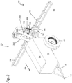
- the distribution machine 10 is according to the Figures 1 , 2nd and 3rd each designed as an agricultural distribution machine 10 that can be coupled or towed by means of a towing vehicle.
- the distribution machine 10 according to the invention could, however, also be a self-propelled and / or a distribution machine 10 which can be attached to a towing vehicle.
- the distribution machine 10 in each case comprises a frame structure 12 for supporting the assemblies of the distribution machine 10, a connecting device 14 (according to FIG Figures 1 to 3 in the form of a towing eye), which connecting device 14 is designed in such a way that the distributor 10 can be connected to a towing vehicle, not shown.
- this also comprises a carriage 16, which carriage 16 comprises two running wheels according to the exemplary embodiments. It would also be conceivable for the undercarriage 16 to be formed by one or more tape drives or caterpillar drives.
- a storage container 18 is also attached to the frame structure 12 for carrying and / or providing the spreading material.
- the storage container 18 can have one or more chambers 20 (cf. Figure 1D and 2D ).
- the chambers 20 have the same volume, whereby they can also have different volumes, so that an adaptation to the amount of spreading material required in each case is made possible.
- the chambers 20 are also formed by an intermediate plate 22 in a common welding assembly.
- the chambers 20 can also be formed by an intermediate plate 22 in an assembly module.
- the chambers 20 could also be formed by a plurality of welding assemblies and / or plastic tanks and / or assembly assemblies, which in turn can form the storage container 18 as a unit.
- the storage container 18 has a cover element 24.
- cover element 24 also a common cover element 24.
- the storage container 18 or the chambers 20 or at least one of the chambers 20 can be designed to be pressure-tight.
- the reservoir 18 or the chambers 20 or at least one of the chambers 20 could also be pressurized.
- this has a distribution linkage 50 extending transversely to the direction of travel FR.
- the distribution linkage 50 has a support 52 connected to the frame construction 12, a central part 54 and side arms 56 pivotally attached to the central part 54.
- the distribution linkage 50 can have working widths of 20 meters, 30 meters or more, for example.
- the distribution linkage 50 is also rotatably attached to or on the carrier 52 by means of a bearing 58.
- the distribution linkage 50 is rotatably supported transversely to the direction of travel by means of the bearing 58.
- the bearing 58 is an axis or axis of rotation oriented parallel to the direction of travel, whereby other design variants would also be conceivable.
- the bearing 58 could also be an at least partially spherical element, about which at least partially spherical element the distribution linkage 50 can rotate transversely to the direction of travel.
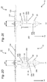
- the side arms 56 can be upright (see, for example, Figure 2A ) and / or pivotally attached to the central part 54 about horizontal axes.
- the side arms 56 can also be composed of two or more segments, which segments can in turn be pivotable relative to one another about upright and / or horizontal axes.
- the distribution linkage 50 or the middle part 54 and / or the side brackets 56 are also at least in sections due to a truss or a truss structure educated.
- the truss or the truss structure also has a greater height than depth.
- the distribution linkage 50 is also attached to the frame structure 12 so as to be adjustable in height, in order to be able to control and / or regulate the height of the distribution linkage 50 relative to a frame construction 12 or to a floor surface or a plant population.
- the height is adjusted by means of a parallelogram 60 arranged between the frame structure 12 and the support 52 and at least one actuator 62 assigned to the parallelogram 60, the actuator 62 according to the figures being a hydraulically or pneumatically operated linear drive, in particular a cylinder.
- a metering device 100 forming a structural unit with the distribution linkage 50 is provided, by means of which metering device 100 the desired quantity can be metered into a plurality of distribution lines 150 attached to the distribution linkage 50.
- the distribution lines 150 each extend from the metering device 100 in different lengths along the distribution linkage 50.
- the distribution lines 150 have a distribution element 152 at its outer end, it also being possible for two or more distribution elements 152 to be provided on a distribution line 150 are attached so that, for example, a distribution element 152 is attached in the course and a further distribution element 152 is attached to the outer end of the distribution line 150.
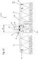
- the distribution element 152 is formed in each case by a baffle plate 154, against which baffle plate 154 the grit is conveyed by means of an air volume flow and by means of which baffle plate 154 the grit is then distributed in a fan shape in the direction of a soil surface or a plant stock (see Figure 1A and 2A ).
- the spreading fans generated by the distribution elements 152 in areas in which there are no useful plants and / or in areas of the lane of the chassis 16 can each be adapted such that no spreading material is spread in these areas. This can be achieved, for example, by means of a distribution element 152, by means of which an asymmetrical scatter fan is generated.
- the means of The metering device 100 into the distribution lines 150 with such distribution elements 152 is accordingly reduced or adapted amount of grit.
- the agricultural distribution mesh is designed as a pneumatic fertilizer spreader, which means that the spreading material is conveyed by the metering device 100 along the distribution lines 150 by means of an air volume flow in the direction of the distribution elements 152.
- the distribution lines 150 are connected by means of at least one flow generating device 200.
- the flow generating device 200 is formed in particular by one or more fans.
- the flow generating device 200 is in particular designed in such a way that different air volume flows can be generated in the distribution lines 150, in particular air volume flows with different flow rates.
- the flow generating device 200 can be operated at different speeds by means of a motor drive.
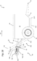
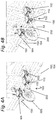
- the flow generating device 200 is in each case assigned to the distribution linkage 50. As especially from the Figures 1B and 2 B and FIGS. 4A and 4B can be seen, the flow generating device 200 thus forms a structural unit with the distribution linkage 50, the flow generation device 200 being attached to a holding device 64 connected to the distribution linkage 50, and thus being permanently connected.
- an air flow divider 202 is assigned to the flow generating device 200.
- the air flow divider 202 opens into the flow generating device 200 and has a plurality of connections, corresponding to the number of distribution lines 150.
- the airflow divider 202 in turn forms a structural unit with the distribution linkage 50.
- the metering device 100 is supplied by means of a conveyor system 250 arranged between the storage container 18 and the distribution linkage 50.
- a conveyor system 250 is provided, the conveyor system 250 in the Figures are shown in greatly simplified form as a connection 252 in the form of a pipeline.
- the conveyor system 250 is expediently designed in such a way that the amount of spreading material conveyed can be varied variably, i.e. Is controllable and / or regulatable.
- the variation of the spreading material in particular through a variation i.e. can be done by controlling and / or regulating a drive system 254 of the conveyor system 250.
- Such a variation can be, for example, an increase or decrease in a drive speed.
- the amount of spreading material conveyed by means of the conveyor system 250 can be varied depending on the amount of spreading material metered by means of the metering device 100.
- the conveyor system 250 is composed of several sections, which sections are also at an angle ⁇ (cf. Figure 2B ) are arranged to each other. Wherein the angle ⁇ can also be changeable, in particular can be changeable depending on the height of the distribution linkage 50.
- the conveyor system 250 is according to the Figures 1 and 2nd formed by screw conveyors 256.
- a conveyor belt and / or a plurality of conveyor belt sections would also be conceivable, which in turn can be arranged at an angle ⁇ .
- a combination of screw conveyor 256 and conveyor belt would also be conceivable or usable, which in turn can be arranged at an angle ⁇ to one another.
- the conveyor system 250 is designed as a pneumatic conveyor system 250, in which the spreading material from the reservoir 18 is present by means of an air volume flow from the reservoir 18 arranged in a conveyor line arranged between the reservoir 18 and the distribution linkage 50 and / or the metering device to the metering device 100 or to the distribution unit 156 and / or to the container 158, in such an embodiment variant the drive system 254 could be formed by a blower.
- the conveyor system 250 runs at least in sections along the outer contour of the storage container 18 or along the bottom surface and a side wall.
- the conveyor system 250 has an inlet 258, which inlet 258 is assigned to the outlet 258 of the funnel-shaped storage container 18 or the chamber 20 of the storage container 18. According to the exemplary embodiments, the conveyor system 250 thus forms the bottom or the outlet 258 of the storage container 18.
- the inlet 258 can be assigned a cover 260 which can be changed or displaced in its position, it being possible to define which area of the storage container 18 is to be emptied first or last by a corresponding change in the position.
- the spreading material conveyed by means of the conveyor system 250 is conveyed in or towards a distribution unit 156.
- the distribution unit 156 uses the distribution unit 156 to divide the grit into a plurality of outlets 160, from which outlets 160 the grit can in turn be forwarded to the metering device 100 by means of lines 162 (only a few are shown for simplicity).
- the distribution unit 156 can in turn be subjected to an air volume flow.
- the distribution unit 156 in accordance with the exemplary embodiments in turn forms a structural unit with the distribution linkage 50.
- the spreading material conveyed by means of the conveyor system 250 is conveyed in or towards a container 158, in particular with the distribution linkage 50, from which container 158 the spreading material is subsequently fed the metering device 100 is passed on.
- the number of distribution units 156 or containers 158 in turn corresponds to the number of conveyor systems 250 and thus the number of different spreading materials.
- the metering device 100 and the distribution linkage 50 form such a structural unit that the movements of the distribution linkage 50 are carried out synchronously and / or at least largely synchronously by the metering device 100.
- each dosing unit can be supplied with a line with grit
- each dosing unit can be supplied with grit with two lines
- the dosing device 100 comprises a plurality of dosing units 102, it also being provided that a dosing unit 102 is assigned to each distribution line 150.
- the spreading material is preferably supplied by means of the metering units 102 to the distribution lines 150 with variable quantities.
- the dosing units 102 can each be operated independently of one another, i.e. each dosing unit 102 can have its own motor drive MA, by means of which the speeds of the dosing units 102 can in turn be variably changed.
- the metering units 102 can be activated or deactivated independently of one another by means of the motor drive MA.
- the grit is in each case metered into distribution lines 150 and conveyed in the direction of the distribution elements 152 by an air volume flow present at least in the distribution lines 150.
- the metering unit 102 is designed here as a cellular wheel sluice 104, ie a rotor 108 which is rotatably driven by a motor drive MA is arranged in a housing 106.
- the rotor 108 each has openings or cutouts which are filled with grit during operation.
- the amount of spreading material metered by means of the metering unit 102 can be changed, ie increased or decreased.
- two rotors 108 are arranged in the housing 106, ie two metering units 102 are thus formed by means of a housing 106.
- a motor drive MA is in turn assigned to each rotor 108.
- the motor drive MA according to the Figure 5 is an electric motor.
- other design variants of motor drives MA would also be conceivable or usable, for example also hydraulically operated motors.
- a drop lock 110 can be provided for connecting 252 the metering device 100 to the distribution lines 150. It can be provided in each case that a drop lock 110 is arranged downstream of each housing 106, the number of connections of drop lock 110 again being identical and / or different from the number of drop locks 110 connected to it.
- the sluice gate 110 is connected to the air flow divider 202 or to the flow generating device 200.
- Each distribution line 150 with a distribution element 152 arranged thereon can also correspond to a so-called partial width, so that partial widths can also be switched, for example, by activating and / or deactivating the metering unit 102.
- Each section can correspond to a working width of 1.5 meters or more or less, for example.
- elements that influence the flow of grit such as flaps for closing or releasing the grit dosing by means of the dosing unit 102 into the sluice 110 or into the distribution lines 150, are attached.
- the flaps can also be manually adjustable and / or automated or adjustable by means of adjusting elements.
- the components forming a structural unit with the distribution linkage 50 ie the metering device 100 and / or the flow generating device 200 and / or the Containers 158 and / or the distribution unit 156 and / or the air flow divider 202 and / or the fall lock 110) are attached to the carrier 52 and / or that they are attached to the central part 54 of the distribution linkage 50.
- the components are attached to the distribution linkage 50 in such a way that its center of gravity SP is at least approximately in the middle, ie in the center of the distribution linkage 50 and / or that the center of gravity SP is in an area which is only one has a small distance from the center of the distribution linkage 50, for example a maximum of 25 cm or 50 cm or 100 cm from the center (see dashed lines in FIG Figures 1D, 1E and 2D, 2E ), the center in turn being located on a plane oriented parallel to the direction of travel, and this plane in turn being able to intersect the bearing 58.
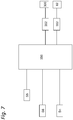
- FIG Figure 7 A control and / or regulating system for varying the rotational position and / or the height of the distribution linkage is shown here, in particular a control and / or regulating system of an actuating device 300 and / or an actuator 62.
- the control and / or regulation system initially comprises a sensor arrangement S5 for determining and / or evaluating an altitude (for example by means of Ultrasonic sensors or distance sensors or the like.) Of the distribution linkage 50, in particular in relation to a frame construction 12 of the distribution machine 10 or to a floor surface or a crop.
- the open-loop and / or closed-loop control system also includes a sensor arrangement S6 for determining and / or evaluating a rotational position of the distribution linkage 50 in relation to the carrier 52 and / or a frame construction 12 of the distribution machine 10.
- further sensor arrangements Sn would be possible or conceivable.
- a sensor arrangement for determining and / or evaluating the movements of the actuating device 300 and / or the at least one actuator 62 would be conceivable.
- the output signals of the sensor arrangements S5; S6; Sn generates and / or outputs control and / or regulation signals for the actuating device 300 and / or the at least one actuator 62 for automated control and / or regulation of the distribution linkage 50.
- a valve 352 can expediently be controlled and / or regulated and / or parameterized by means of the data processing device 350, by means of which valve 352 in turn the actuating device 300 and / or the actuators 62 can be controlled and / or regulated.
- the container 158 or the distribution unit 156 can be assigned a sensor arrangement S2 for determining and / or evaluating its fill level, the fill level being transmitted to a data processing device 350.
- the metering unit 102 is in turn associated with a sensor arrangement S2 for determining and / or evaluating the metered amount of spreading material. These values can also be transferred to a data processing device. A determination and / or evaluation of the metered quantity is also based on the rotor used and the speed at which the rotor is driven, which can be determined and / or evaluated by means of the data processing device 350.
- a further sensor arrangement S3 is provided for determining and / or evaluating the spreading fans, or for monitoring the Distribution elements 152.
- the sensor arrangement S3 can in turn be used to evaluate the distributed quantity of spreading material by means of the data processing device 350.
- a valve 352 or the like is then in turn actuated by means of the data processing device 350 and thus a drive system 254 of the conveyor system 250 is activated or deactivated and / or by of the conveyor system 250 increased or decreased amount of grit.
Landscapes
- Life Sciences & Earth Sciences (AREA)
- Soil Sciences (AREA)
- Environmental Sciences (AREA)
- Fertilizing (AREA)
Applications Claiming Priority (1)
| Application Number | Priority Date | Filing Date | Title |
|---|---|---|---|
| DE102018131070.6A DE102018131070A1 (de) | 2018-12-05 | 2018-12-05 | Verteilmaschine zum Ausbringen von körnigem landwirtschaftlichem Streugut und Verfahren zur Verteilung von körnigem landwirtschaftlichem Streugut |
Publications (3)
| Publication Number | Publication Date |
|---|---|
| EP3662735A1 true EP3662735A1 (fr) | 2020-06-10 |
| EP3662735B1 EP3662735B1 (fr) | 2024-02-28 |
| EP3662735C0 EP3662735C0 (fr) | 2024-02-28 |
Family
ID=68699282
Family Applications (1)
| Application Number | Title | Priority Date | Filing Date |
|---|---|---|---|
| EP19211736.4A Active EP3662735B1 (fr) | 2018-12-05 | 2019-11-27 | Machine de distribution pour épander un matériau d'épandage agricole granulaire et procédé pour distribuer un matériau d'épandage agricole granulaire |
Country Status (3)
| Country | Link |
|---|---|
| EP (1) | EP3662735B1 (fr) |
| DE (1) | DE102018131070A1 (fr) |
| UA (1) | UA128782C2 (fr) |
Cited By (1)
| Publication number | Priority date | Publication date | Assignee | Title |
|---|---|---|---|---|
| CN116686517A (zh) * | 2023-06-30 | 2023-09-05 | 广西壮族自治区农业科学院 | 一种玉米施肥机 |
Families Citing this family (3)
| Publication number | Priority date | Publication date | Assignee | Title |
|---|---|---|---|---|
| DE102021104407A1 (de) | 2021-02-24 | 2022-08-25 | Horsch Leeb Application Systems Gmbh | Landwirtschaftliche verteilmaschine und verfahren zum betreiben einer derartigen landwirtschaftlichen verteilmaschine |
| DE102022103794A1 (de) | 2022-02-17 | 2023-08-17 | Horsch Leeb Application Systems Gmbh | Pneumatischer Düngerstreuer |
| CN116420485B (zh) * | 2023-06-12 | 2023-08-25 | 大同市现代农业发展中心 | 一种基于物联网的智能变量施肥装置 |
Citations (4)
| Publication number | Priority date | Publication date | Assignee | Title |
|---|---|---|---|---|
| US5125583A (en) * | 1986-03-17 | 1992-06-30 | Tyler Limited Partnership | Truck mounted fertilizer applicator using fluid conveying |
| US5178333A (en) * | 1991-12-06 | 1993-01-12 | Larry Barber | Air distribution apparatus for particulates |
| US20160095276A1 (en) * | 2014-10-02 | 2016-04-07 | Cnh Industrial Canada, Ltd. | Pheumatic delivery system for application implement using multiple metering devices |
| DE102017005093A1 (de) * | 2017-05-29 | 2018-11-29 | Rauch Landmaschinenfabrik Gmbh | Pneumatische Verteilmaschine und Verfahren zum Ausbringen von Verteilgut mit derselben |
-
2018
- 2018-12-05 DE DE102018131070.6A patent/DE102018131070A1/de active Pending
-
2019
- 2019-11-27 EP EP19211736.4A patent/EP3662735B1/fr active Active
- 2019-12-02 UA UAA201911590A patent/UA128782C2/uk unknown
Patent Citations (4)
| Publication number | Priority date | Publication date | Assignee | Title |
|---|---|---|---|---|
| US5125583A (en) * | 1986-03-17 | 1992-06-30 | Tyler Limited Partnership | Truck mounted fertilizer applicator using fluid conveying |
| US5178333A (en) * | 1991-12-06 | 1993-01-12 | Larry Barber | Air distribution apparatus for particulates |
| US20160095276A1 (en) * | 2014-10-02 | 2016-04-07 | Cnh Industrial Canada, Ltd. | Pheumatic delivery system for application implement using multiple metering devices |
| DE102017005093A1 (de) * | 2017-05-29 | 2018-11-29 | Rauch Landmaschinenfabrik Gmbh | Pneumatische Verteilmaschine und Verfahren zum Ausbringen von Verteilgut mit derselben |
Cited By (1)
| Publication number | Priority date | Publication date | Assignee | Title |
|---|---|---|---|---|
| CN116686517A (zh) * | 2023-06-30 | 2023-09-05 | 广西壮族自治区农业科学院 | 一种玉米施肥机 |
Also Published As
| Publication number | Publication date |
|---|---|
| EP3662735B1 (fr) | 2024-02-28 |
| BR102019025632A2 (pt) | 2020-06-16 |
| EP3662735C0 (fr) | 2024-02-28 |
| DE102018131070A1 (de) | 2020-06-10 |
| UA128782C2 (uk) | 2024-10-23 |
Similar Documents
| Publication | Publication Date | Title |
|---|---|---|
| EP3501250B1 (fr) | Épandeur agricole et procédé de commande de rangée simple et groupée d'un tel épandeur agricole | |
| EP3338524B1 (fr) | Semoir monograine agricole et procédé | |
| EP3662735B1 (fr) | Machine de distribution pour épander un matériau d'épandage agricole granulaire et procédé pour distribuer un matériau d'épandage agricole granulaire | |
| EP3409090B1 (fr) | Machine d'épandage pneumatique et procédé de distribution de produit à épandre au moyen de ladite machine d'épandage pneumatique | |
| EP3000299B1 (fr) | Dispositif de distribution pour marchandises en grains | |
| EP3662734B1 (fr) | Système de commande et / ou de régulation pour une machine de distribution agricole, machine de distribution agricole et procédé de commande et / ou de régulation d'une machine de distribution agricole | |
| WO2017055266A1 (fr) | Tour de distribution d'une machine de distribution agricole et procédé pour la mise hors circuit en série sur une telle tour de distribution | |
| EP2022329A2 (fr) | Dispositif de pulvérisation mobile doté d'une tige de pulvérisation et procédé de réglage de ses buses de pulvérisation | |
| EP2932818A1 (fr) | Dispositif d'épandage et procédé d'extraction du produit à épandre sous forme de granulés | |
| DE102011054862A1 (de) | Bodenbearbeitungsgerät und Verfahren zur Einbringung von wasserspeicherndem Material und/oder Düngemittel und/oder Saatgut in den Erdboden | |
| EP4349148A1 (fr) | Machine de distribution pneumatique et procédé de régulation du débit massique de son organe de dosage | |
| DE102018131071A1 (de) | Verteilmaschine zum Ausbringen von körnigem landwirtschaftlichem Streugut mit einem verbesserten Fördersystem und Verfahren zum Fördern von körnigem landwirtschaftlichem Streugut | |
| EP3804516B1 (fr) | Machine d'épandage agricole, de préférence pulvérisateur ou distributeur d'engrais | |
| DE102007038510B4 (de) | Vorrichtung zum Dosieren und Verteilen von landwirtschaftlichen und kommunalen Schüttgütern | |
| DE102019007588A1 (de) | Pneumatische Verteilmaschine | |
| EP3662733B1 (fr) | Machine d'épandage agricole et dispositif de dosage pour une machine d'épandage agricole | |
| DE102020003359A1 (de) | Verteilmaschine, insbesondere pneumatischer Düngerstreuer | |
| DE102018131072A1 (de) | Steuerungs- und/oder Regelungssystem für ein Verteilgestänge eines pneumatischen Düngerstreuers, pneumatischer Düngerstreuer und Verfahren zur Steuerung- und/oder Regelung eines pneumatischen Düngerstreuers | |
| DE102018001875A1 (de) | Zweischeibenstreuer mit hydraulischem Antrieb der Verteilerscheiben | |
| DE102020114760A1 (de) | Verteilmaschine, insbesondere pneumatischer Düngerstreuer und Verfahren zum Einstellen einer Dosiervorrichtung einer Verteilmaschine | |
| EP3175694B1 (fr) | Procédé d'épandage de produit d'épandage agricole, commande pour une épandeuse pour produit d'épandage agricole, et épandeuse pour produit d'épandage agricole | |
| DE102023115652A1 (de) | Tragstruktur für ein landwirtschaftliches arbeitsgerät zur ausbringung eines landwirtschaftlichen guts auf einem boden, arbeitsgerät mit einer tragstruktur und verfahren zum ausbringen eines landwirtschaftlichen guts | |
| EP3508047A1 (fr) | Dispositif d'épandage du produit d'épandage sur des surfaces agricoles | |
| EP4260701A1 (fr) | Machine de distribution agricole et procédé d'épandage de produit de distribution agricole | |
| DE102024112921A1 (de) | Pneumatischer Düngerstreuer und Verfahren zum Ausbringen von körnigem landwirtschaftlichem Streugut |
Legal Events
| Date | Code | Title | Description |
|---|---|---|---|
| PUAI | Public reference made under article 153(3) epc to a published international application that has entered the european phase |
Free format text: ORIGINAL CODE: 0009012 |
|
| STAA | Information on the status of an ep patent application or granted ep patent |
Free format text: STATUS: THE APPLICATION HAS BEEN PUBLISHED |
|
| AK | Designated contracting states |
Kind code of ref document: A1 Designated state(s): AL AT BE BG CH CY CZ DE DK EE ES FI FR GB GR HR HU IE IS IT LI LT LU LV MC MK MT NL NO PL PT RO RS SE SI SK SM TR |
|
| AX | Request for extension of the european patent |
Extension state: BA ME |
|
| RAP1 | Party data changed (applicant data changed or rights of an application transferred) |
Owner name: HORSCH LEEB APPLICATION SYSTEMS GMBH |
|
| STAA | Information on the status of an ep patent application or granted ep patent |
Free format text: STATUS: REQUEST FOR EXAMINATION WAS MADE |
|
| 17P | Request for examination filed |
Effective date: 20201209 |
|
| RBV | Designated contracting states (corrected) |
Designated state(s): AL AT BE BG CH CY CZ DE DK EE ES FI FR GB GR HR HU IE IS IT LI LT LU LV MC MK MT NL NO PL PT RO RS SE SI SK SM TR |
|
| GRAP | Despatch of communication of intention to grant a patent |
Free format text: ORIGINAL CODE: EPIDOSNIGR1 |
|
| STAA | Information on the status of an ep patent application or granted ep patent |
Free format text: STATUS: GRANT OF PATENT IS INTENDED |
|
| INTG | Intention to grant announced |
Effective date: 20230922 |
|
| GRAS | Grant fee paid |
Free format text: ORIGINAL CODE: EPIDOSNIGR3 |
|
| GRAA | (expected) grant |
Free format text: ORIGINAL CODE: 0009210 |
|
| STAA | Information on the status of an ep patent application or granted ep patent |
Free format text: STATUS: THE PATENT HAS BEEN GRANTED |
|
| AK | Designated contracting states |
Kind code of ref document: B1 Designated state(s): AL AT BE BG CH CY CZ DE DK EE ES FI FR GB GR HR HU IE IS IT LI LT LU LV MC MK MT NL NO PL PT RO RS SE SI SK SM TR |
|
| REG | Reference to a national code |
Ref country code: GB Ref legal event code: FG4D Free format text: NOT ENGLISH |
|
| REG | Reference to a national code |
Ref country code: CH Ref legal event code: EP |
|
| REG | Reference to a national code |
Ref country code: DE Ref legal event code: R096 Ref document number: 502019010664 Country of ref document: DE |
|
| REG | Reference to a national code |
Ref country code: IE Ref legal event code: FG4D Free format text: LANGUAGE OF EP DOCUMENT: GERMAN |
|
| U01 | Request for unitary effect filed |
Effective date: 20240307 |
|
| U07 | Unitary effect registered |
Designated state(s): AT BE BG DE DK EE FI FR IT LT LU LV MT NL PT SE SI Effective date: 20240408 |
|
| PG25 | Lapsed in a contracting state [announced via postgrant information from national office to epo] |
Ref country code: IS Free format text: LAPSE BECAUSE OF FAILURE TO SUBMIT A TRANSLATION OF THE DESCRIPTION OR TO PAY THE FEE WITHIN THE PRESCRIBED TIME-LIMIT Effective date: 20240628 |
|
| PG25 | Lapsed in a contracting state [announced via postgrant information from national office to epo] |
Ref country code: GR Free format text: LAPSE BECAUSE OF FAILURE TO SUBMIT A TRANSLATION OF THE DESCRIPTION OR TO PAY THE FEE WITHIN THE PRESCRIBED TIME-LIMIT Effective date: 20240529 |
|
| PG25 | Lapsed in a contracting state [announced via postgrant information from national office to epo] |
Ref country code: RS Free format text: LAPSE BECAUSE OF FAILURE TO SUBMIT A TRANSLATION OF THE DESCRIPTION OR TO PAY THE FEE WITHIN THE PRESCRIBED TIME-LIMIT Effective date: 20240528 Ref country code: HR Free format text: LAPSE BECAUSE OF FAILURE TO SUBMIT A TRANSLATION OF THE DESCRIPTION OR TO PAY THE FEE WITHIN THE PRESCRIBED TIME-LIMIT Effective date: 20240228 |
|
| PG25 | Lapsed in a contracting state [announced via postgrant information from national office to epo] |
Ref country code: ES Free format text: LAPSE BECAUSE OF FAILURE TO SUBMIT A TRANSLATION OF THE DESCRIPTION OR TO PAY THE FEE WITHIN THE PRESCRIBED TIME-LIMIT Effective date: 20240228 |
|
| PG25 | Lapsed in a contracting state [announced via postgrant information from national office to epo] |
Ref country code: RS Free format text: LAPSE BECAUSE OF FAILURE TO SUBMIT A TRANSLATION OF THE DESCRIPTION OR TO PAY THE FEE WITHIN THE PRESCRIBED TIME-LIMIT Effective date: 20240528 Ref country code: NO Free format text: LAPSE BECAUSE OF FAILURE TO SUBMIT A TRANSLATION OF THE DESCRIPTION OR TO PAY THE FEE WITHIN THE PRESCRIBED TIME-LIMIT Effective date: 20240528 Ref country code: IS Free format text: LAPSE BECAUSE OF FAILURE TO SUBMIT A TRANSLATION OF THE DESCRIPTION OR TO PAY THE FEE WITHIN THE PRESCRIBED TIME-LIMIT Effective date: 20240628 Ref country code: HR Free format text: LAPSE BECAUSE OF FAILURE TO SUBMIT A TRANSLATION OF THE DESCRIPTION OR TO PAY THE FEE WITHIN THE PRESCRIBED TIME-LIMIT Effective date: 20240228 Ref country code: GR Free format text: LAPSE BECAUSE OF FAILURE TO SUBMIT A TRANSLATION OF THE DESCRIPTION OR TO PAY THE FEE WITHIN THE PRESCRIBED TIME-LIMIT Effective date: 20240529 Ref country code: ES Free format text: LAPSE BECAUSE OF FAILURE TO SUBMIT A TRANSLATION OF THE DESCRIPTION OR TO PAY THE FEE WITHIN THE PRESCRIBED TIME-LIMIT Effective date: 20240228 |
|
| PG25 | Lapsed in a contracting state [announced via postgrant information from national office to epo] |
Ref country code: PL Free format text: LAPSE BECAUSE OF FAILURE TO SUBMIT A TRANSLATION OF THE DESCRIPTION OR TO PAY THE FEE WITHIN THE PRESCRIBED TIME-LIMIT Effective date: 20240228 |
|
| PG25 | Lapsed in a contracting state [announced via postgrant information from national office to epo] |
Ref country code: PL Free format text: LAPSE BECAUSE OF FAILURE TO SUBMIT A TRANSLATION OF THE DESCRIPTION OR TO PAY THE FEE WITHIN THE PRESCRIBED TIME-LIMIT Effective date: 20240228 |
|
| PG25 | Lapsed in a contracting state [announced via postgrant information from national office to epo] |
Ref country code: SM Free format text: LAPSE BECAUSE OF FAILURE TO SUBMIT A TRANSLATION OF THE DESCRIPTION OR TO PAY THE FEE WITHIN THE PRESCRIBED TIME-LIMIT Effective date: 20240228 |
|
| PG25 | Lapsed in a contracting state [announced via postgrant information from national office to epo] |
Ref country code: CZ Free format text: LAPSE BECAUSE OF FAILURE TO SUBMIT A TRANSLATION OF THE DESCRIPTION OR TO PAY THE FEE WITHIN THE PRESCRIBED TIME-LIMIT Effective date: 20240228 |
|
| PG25 | Lapsed in a contracting state [announced via postgrant information from national office to epo] |
Ref country code: SK Free format text: LAPSE BECAUSE OF FAILURE TO SUBMIT A TRANSLATION OF THE DESCRIPTION OR TO PAY THE FEE WITHIN THE PRESCRIBED TIME-LIMIT Effective date: 20240228 |
|
| PG25 | Lapsed in a contracting state [announced via postgrant information from national office to epo] |
Ref country code: SM Free format text: LAPSE BECAUSE OF FAILURE TO SUBMIT A TRANSLATION OF THE DESCRIPTION OR TO PAY THE FEE WITHIN THE PRESCRIBED TIME-LIMIT Effective date: 20240228 Ref country code: SK Free format text: LAPSE BECAUSE OF FAILURE TO SUBMIT A TRANSLATION OF THE DESCRIPTION OR TO PAY THE FEE WITHIN THE PRESCRIBED TIME-LIMIT Effective date: 20240228 Ref country code: RO Free format text: LAPSE BECAUSE OF FAILURE TO SUBMIT A TRANSLATION OF THE DESCRIPTION OR TO PAY THE FEE WITHIN THE PRESCRIBED TIME-LIMIT Effective date: 20240228 Ref country code: CZ Free format text: LAPSE BECAUSE OF FAILURE TO SUBMIT A TRANSLATION OF THE DESCRIPTION OR TO PAY THE FEE WITHIN THE PRESCRIBED TIME-LIMIT Effective date: 20240228 |
|
| REG | Reference to a national code |
Ref country code: DE Ref legal event code: R097 Ref document number: 502019010664 Country of ref document: DE |
|
| U20 | Renewal fee for the european patent with unitary effect paid |
Year of fee payment: 6 Effective date: 20241125 |
|
| PLBE | No opposition filed within time limit |
Free format text: ORIGINAL CODE: 0009261 |
|
| STAA | Information on the status of an ep patent application or granted ep patent |
Free format text: STATUS: NO OPPOSITION FILED WITHIN TIME LIMIT |
|
| 26N | No opposition filed |
Effective date: 20241129 |
|
| REG | Reference to a national code |
Ref country code: CH Ref legal event code: PL |
|
| PG25 | Lapsed in a contracting state [announced via postgrant information from national office to epo] |
Ref country code: MC Free format text: LAPSE BECAUSE OF FAILURE TO SUBMIT A TRANSLATION OF THE DESCRIPTION OR TO PAY THE FEE WITHIN THE PRESCRIBED TIME-LIMIT Effective date: 20240228 |
|
| REG | Reference to a national code |
Ref country code: CH Ref legal event code: PL |
|
| GBPC | Gb: european patent ceased through non-payment of renewal fee |
Effective date: 20241127 |
|
| PG25 | Lapsed in a contracting state [announced via postgrant information from national office to epo] |
Ref country code: CH Free format text: LAPSE BECAUSE OF NON-PAYMENT OF DUE FEES Effective date: 20241130 |
|
| PG25 | Lapsed in a contracting state [announced via postgrant information from national office to epo] |
Ref country code: GB Free format text: LAPSE BECAUSE OF NON-PAYMENT OF DUE FEES Effective date: 20241127 |
|
| PG25 | Lapsed in a contracting state [announced via postgrant information from national office to epo] |
Ref country code: IE Free format text: LAPSE BECAUSE OF NON-PAYMENT OF DUE FEES Effective date: 20241127 |
|
| U20 | Renewal fee for the european patent with unitary effect paid |
Year of fee payment: 7 Effective date: 20251117 |
|
| PG25 | Lapsed in a contracting state [announced via postgrant information from national office to epo] |
Ref country code: HU Free format text: LAPSE BECAUSE OF FAILURE TO SUBMIT A TRANSLATION OF THE DESCRIPTION OR TO PAY THE FEE WITHIN THE PRESCRIBED TIME-LIMIT; INVALID AB INITIO Effective date: 20191127 |
|
| PG25 | Lapsed in a contracting state [announced via postgrant information from national office to epo] |
Ref country code: CY Free format text: LAPSE BECAUSE OF FAILURE TO SUBMIT A TRANSLATION OF THE DESCRIPTION OR TO PAY THE FEE WITHIN THE PRESCRIBED TIME-LIMIT; INVALID AB INITIO Effective date: 20191127 |