EP3662738A1 - Moissonneuse-batteuse automotrice - Google Patents
Moissonneuse-batteuse automotrice Download PDFInfo
- Publication number
- EP3662738A1 EP3662738A1 EP19202917.1A EP19202917A EP3662738A1 EP 3662738 A1 EP3662738 A1 EP 3662738A1 EP 19202917 A EP19202917 A EP 19202917A EP 3662738 A1 EP3662738 A1 EP 3662738A1
- Authority
- EP
- European Patent Office
- Prior art keywords
- suction fan
- air
- fan arrangement
- arrangement
- combine
- Prior art date
- Legal status (The legal status is an assumption and is not a legal conclusion. Google has not performed a legal analysis and makes no representation as to the accuracy of the status listed.)
- Granted
Links
Images


Classifications
-
- A—HUMAN NECESSITIES
- A01—AGRICULTURE; FORESTRY; ANIMAL HUSBANDRY; HUNTING; TRAPPING; FISHING
- A01D—HARVESTING; MOWING
- A01D41/00—Combines, i.e. harvesters or mowers combined with threshing devices
- A01D41/12—Details of combines
- A01D41/1243—Devices for laying-out or distributing the straw
Definitions
- the present invention relates to a self-propelled combine harvester, comprising a threshing device, a separating device, a cleaning device, which is followed by a suction fan arrangement with at least one housing, at least one inlet opening and at least one outlet opening, a chopping device and at least one distribution device for accepting and discharging a chopper passing through the chopping device Gutstrom.
- the combine harvester comprises a threshing device, a separating device, a cleaning device, which is followed by a suction fan arrangement with at least one housing, at least one inlet opening and at least one outlet opening, a chopping device and at least one distribution device for accepting and discharging a crop flow passing through the chopping device.
- the suction blower arrangement is designed as a cleaning blower of the cleaning device and serves to convey a material stream consisting of short grain, chaff and the like consisting essentially of non-grain components out of a machine housing of the combine harvester and to transfer it to a distribution device which distributes the material flow over a distribution width on the field soil .
- the chopping device is used to shred the material stream essentially consisting of straw coming from the separating device.
- the material flows fed to the distribution device are each accelerated by the chopping device and by the suction fan arrangement before they are mixed with one another in the distribution device before the distribution. This mixing of the different, accelerated crop flows can influence the quality of the distribution and the distribution width.
- the invention has for its object to develop a self-propelled combine harvester of the type mentioned, which is characterized by an improved distribution of the crop flows transferred to the distribution device.
- a self-propelled combine harvester comprising a threshing device, a separating device, a cleaning device, which is followed by a suction fan arrangement with at least one housing, at least one inlet opening and at least one outlet opening, a chopping device and at least one distribution device for receiving and discharging the chopping device continuous flow of material, proposed, wherein the at least one inlet opening of the suction blower arrangement faces the cleaning device and the at least one outlet opening of the suction blower arrangement is positioned below the chopping device, so that a transfer of an air and material flow sucked in by the suction blower arrangement through the at least one inlet opening to the distribution device in in a lower area of the distribution device, the distribution device in an upper area the material flow passing through the chopping device and in brings the air and material flow to the lower area.
- An upper layer is formed in the upper area, which essentially consists of chopped material.
- the air and material flow forms a lower layer, above which the upper layer flows essentially in parallel.
- the flow of material coming from the chopping device is thereby supported and accelerated the air and material flow coming from the suction fan arrangement when it emerges from the distribution device.
- This has the effect that the crop stream comminuted by the chopping device floats on the air and crop stream of the suction fan arrangement when it emerges from the distribution device, and thus a greater throwing distance or distribution width is achieved.
- the suction fan arrangement generates one intensive airflow than a conventional pressure blower arranged in front of the cleaning device, so that a higher proportion of admixtures and dust can be removed from the combine.
- At least one rotor can be arranged rotating about a horizontal axis in the at least one housing, the at least one housing having two conical housing sections arranged in mirror image, which are arranged coaxially to the horizontal axis.
- the housing sections which are of conical disk shape at least in sections, surround the at least one rotor arranged to rotate about the horizontal axis.
- the at least one inlet opening can be designed as an opening arranged coaxially to the horizontal axis in at least one of the housing sections and the at least one outlet opening can be designed as an opening that extends perpendicularly to a guide segment that bridges a region between the suction fan arrangement and the distribution device.
- the air and material flow sucked in by the at least one rotor is essentially fed into the housing from the front, i.e. essentially parallel to the plane of sieves of the cleaning device.
- the air and material flow is discharged through the at least one outlet opening, which is positioned such that there is an approximately tangential transition of the air and material flow from the at least one outlet opening into the downstream distribution device.
- the guide segment can bridge a free section between the suction fan arrangement and the distribution device, in which the chopping device is positioned.
- the flow of air and material flows over the surface of the guide segment and can thus transport chopped material further in the direction of the distribution device.
- the at least one inlet opening can be delimited in each case by a guide section which extends in sections in the circumferential direction of the horizontal axis and tapers in the axial direction, the guide section is interrupted in sections on its side facing the cleaning device.
- the guiding section serves to assume that the air and material flow coming from the direction of the cleaning device is deflected.
- the arrangement of the guide section is selected such that the interruption in sections enables the air and material flow to be accepted from the front, ie essentially parallel to the plane of the screens of the cleaning device.
- the taper of the respective guide section can cause a deflection of the intake air and material flow into the inlet opening of the housing.
- the respective leading gate can limit the suction of air and material in sections. In particular, the suction can be limited on the side of the respective inlet opening which faces the distribution device.
- cutting elements can be arranged on a shaft rotating about the horizontal axis in the region of the inlet opening.
- the cutting elements can crush the non-grain components in the sucked-in air and material flow in a free cut.
- the cutting elements can be designed as knives or cutting threads.
- the cutting elements can be used to eliminate excess lengths in the straw which, coming from the threshing device and the separating device, reach the cleaning device. An increase in the degree of comminution of the cleaning outlet can be achieved. Leakage losses during the transition to the distribution device can also be reduced.
- the cutting elements can be used to improve field hygiene by destroying weed seeds and lost grains. This results in a reduction in the use of spraying agents and less effort in tillage for weed control.
- the shaft on which the cutting elements are arranged can also drive the at least one rotor.
- baffle plates are arranged on the inside of the housing sections surrounding the rotor.
- the baffle plates can up to be arranged in the region of the outlet opening.
- the baffle plates can preferably be pivoted on the inside of the housing sections. At least the baffle plates in the area of the outlet opening can be removed in order to be able to prevent a build-up in critical harvesting conditions.
- counter knives opposite the at least one cutting element can be arranged on the inside of the housing sections. This enables the degree of comminution of the suctioned cleaning outlet to be increased, which contributes to a further improvement in field hygiene.
- the suction fan arrangement can be transferred from its operating position, in which the air and material flow provided by the suction fan arrangement is transferred to the distribution device, to a transport position, in which the suction fan arrangement is in a position inside the machine housing, by means of a lever arrangement is located below the separator.
- the suction fan arrangement can be designed to be pivotable about a pivot axis.
- the at least one outlet opening of the suction fan arrangement can preferably be formed on at least one channel segment, to which the guide segment adjoins.
- a plurality of channel segments can preferably be arranged lying next to one another in a common, horizontal plane. Each channel segment can have an outlet opening.
- the suction blower arrangement can suck air essentially through a suction area located in front of the cleaning device, at least one air guiding element being arranged in the suction area.
- the at least one air guide element can serve to deflect a partial air flow in the direction of a grain conveyor screw arranged below the cleaning device.
- the cleaned grain which has passed the cleaning device, is fed to a conveyor device which conveys the grain into a grain tank of the combine harvester.
- the redirection of the partial air flow in the direction the auger causes a higher pressure on the auger by increasing the maximum pouring cone, which means that a higher grain recovery rate can be achieved. Grain trickling out at high throughputs can at least be minimized or avoided entirely.
- the at least one air guide element can be designed as a guide plate and / or as louvre-like, in particular adjustable, slats.
- the threshing device, the separating device, the cleaning device, the suction blower arrangement and the chopping device are surrounded by a machine housing, wherein at least in the area of the threshing device and the separating device, closure elements are arranged which serve to deflect the air flow sucked in by the suction blower arrangement inside the machine housing.
- the air flow generated by the suction fan arrangement can be diverted by means of the closure elements in such a way that it specifically flows over or around critical assemblies in order to remove deposits.
- the targeted deflection of the air flow can be used, for example, to remove deposits on the separating device designed as a separating rotor without additional work.
- the closure elements can be controlled automatically. This would enable a cleaning program for the combine's working units.
- a ventilated drop step can be formed between a return tray arranged below the separating device and a conveyor tray arranged below the threshing device.
- the suction blower arrangement can suck in air through the stone trap arranged below the threshing device between the drop stage formed between the return floor and the conveyor floor. The additional flow ensures additional segregation of the crop stream coming from the return floor and discharges chaff to the rear from the combine.
- At least one loss sensor embodied in the area of the at least one outlet opening of the suction fan arrangement can be arranged.
- the at least one loss sensor can be designed as a head sensor.
- the positioning of the suction blower arrangement designed as a cleaning blower downstream of the cleaning device has the advantage that loss grains discharged with the air flow or removed by the cleaning device are sucked in by the suction blower arrangement and pass through them.
- At least one sensor element designed as a radar sensor can be arranged in the region of the at least one outlet opening of the suction fan arrangement.
- the speed of the crop flow, in particular the chaff, can be determined by means of the radar sensor.
- At least one sensor element designed as a baffle plate with a weighing cell can be arranged in the region of the at least one outlet opening of the suction fan arrangement.
- the throughput can be determined in connection with the speed determination by the radar sensor.
- the suction blower arrangement can preferably be set up to separate the chaff sucked in with the air flow and to transfer it to a transport vehicle.
- the chaff can be applied directly to the transport vehicle by means of the air flow.
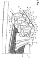
- Combine harvester 1 includes a threshing device 2, which is designed as a multi-drum threshing unit, a separating device 3, which in the exemplary embodiment shown is designed as separating rotors, a cleaning device 4, a chopping device 5, and a distribution device 6, which is designed as a spreading plate distributor.
- the threshing device 2, the separating device 3, the cleaning device 4 and the chopping device 5 are surrounded by a machine housing 7.
- the distribution device 6 is arranged on the outside of the machine housing 7.
- An oscillating driven conveyor floor 8 is arranged below the threshing device 2.
- a return floor 9 is arranged below the separating device 3.
- the cleaning device 4 comprises an upper sieve 10 and a lower sieve 11.
- the cleaning device 4 is a suction fan assembly 12 downstream, which serves as a cleaning fan.
- the suction fan arrangement 12 has at least one housing 13.
- the at least one housing 13 comprises conical housing sections 14 arranged in mirror image.
- the housing sections 14 are coaxial with a horizontal axis 15.
- a guide segment 16 connects to the at least one housing 13.
- the suction fan arrangement 12 draws in an air and material flow 17, which essentially contains chaff, short straw and the like. The air and material flow is essentially sucked in in the area of the threshing device 2 and the cleaning device 4 and passed on from the suction fan arrangement 12 via the guide segment 16 to the distribution device 6.
- the guide segment 16 bridges the horizontally running section between the suction blower arrangement 12 and the distribution device 6. Above the guide segment 16, the chopping device 5 is arranged, which delivers a material flow 34, which essentially consists of shredded straw, to the distribution device 6. The guide segment 16 prevents chopped material from escaping before the distribution device 6 is reached.
- the at least one housing 13 of the suction blower arrangement 12 can be transferable about a horizontal axis 15 from its operating position, in which the air and material flow 17 provided by the suction blower arrangement 12 is transferred to the distribution device 6, into a transport position in which the suction blower arrangement 12 is in a position below the separating device 3 and partially above the cleaning device 4.
- the distribution device 6, designed as a scattering plate distributor, comprises a cover component 18, on the underside of which scattering baffle plates 19 are arranged.
- the scattering baffles 19 are each arranged on the cover component 18 so as to be pivotable about a vertical axis.
- An actuator is arranged in the interior of the cover component 18, by means of which the scattering baffle plates 19 can be pivoted individually or in groups about the vertical axis.
- FIG. 2 a view of the suction fan arrangement 12 with a subsequent chopping device 5 and distribution device 6 is shown schematically.
- a shaft 20 extends coaxially to the horizontal axis 15 and extends at least over the width of the housing 13.
- Runners 21 are arranged on the shaft 20, each of which is surrounded by two of the conical disk-shaped housing sections 14.
- the cone-shaped housing sections 14 taper outwards in the axial direction.
- a channel segment 22 is arranged on the respective housing section 14, into which the air and material flow 17 conveyed by the respective rotor 21 flows. The air and material flow 17 emerging from the channel segments 22 is supplied to the distribution device 6 via the surface of the guide segment 16.
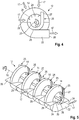
- Fig. 3 schematically shows a perspective view of the suction fan arrangement 12, which is arranged downstream of the cleaning device 4.
- the suction fan arrangement 12 connects to the top sieve 10 of the cleaning device 4.
- Each housing section 14 has an inlet opening 24 through which the horizontal shaft 20 extends.
- the air and material flow 17 is drawn in by the runners 21 through the respective inlet opening 14.
- the area around the respective inlet opening 24, in which the air and material flow 17 is drawn in by the rotors 21, is delimited by guide sections 25 tapering in the axial direction.
- the guide sections 25 prevent an undesired air flow from being sucked in from the area of the chopping device 5.
- the guide sections 25 have a lower semicircular section 26, which is arranged essentially coaxially to the shaft 20 on the housing section 14.
- the semicircular section 26 merges into a straight section 27 which extends essentially vertically to the shaft 20.
- each channel section 22 has an outlet opening 28, from which the air and material flow 17 exits.
- At least one sensor element 23 is arranged in the area of each outlet opening 28 and serves to detect a property of the air and material flow 17.
- the at least one sensor element 23 can be used as a knock sensor to detect lost grains be trained.
- the arrangement of the at least one sensor element 23 takes place on wall areas of the channel section 22, along which the air and material flow 17 mainly flows.
- a radar sensor can be arranged in the respective channel section 22 as the sensor element 23.
- the speed of the material in the air and material flow 17 can be determined by means of the sensor element 23 designed as a radar sensor.
- the throughput could be determined by combining the radar sensor with a further sensor element 23 designed as a baffle plate and a weighing cell arranged thereon.
- FIG. 4 the suction fan arrangement 12 is shown schematically in a side view.
- the respective guide section 25 limits the acceptance of the air and material flow 17 to an approximately quarter-circular area around the inlet opening 24.
- a horizontally running segment 29 extends in the radial direction of the housing section 14 starting from the semicircular section 26 of the guide section 25.
- the respectively horizontally running segments 29 form an acceptance level for the air and material flow 17 coming from the direction of the cleaning device 4.
- the horizontally running segment 29 can be arranged at approximately the same height as the top sieve 10 of the cleaning device 4. This prevents air from being sucked in from below, bypassing the upper sieve 11.
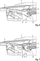
- Fig. 6 shows schematically a partial view of the conveyor floor 8 and the cleaning device 4. Grains which pass through both sieves 10, 11 of the cleaning device 4 fall on an inclined collecting and guide tray 30 and slide into a - not shown - grain conveyor screw, which the grains of Feeds conveyor, by means of which the grain is conveyed into the grain tank. At least one air guiding element 31 is arranged beneath the conveyor base 8 or the sieve 11, which deflects the suction wind generated by the suction fan arrangement 12 proportionally onto the grain conveyor screw. The at least one air guide element 31 is arranged inclined in the longitudinal direction of the combine harvester. That is at least one air guiding element 31 designed as a baffle, which extends at least over the width of the suction area. In Fig.
- FIG. 7 a partial view of conveyor floor 8 and cleaning device 4 with air guiding elements 31, 32 according to a second embodiment is shown schematically.
- a further air guiding element 32 designed as a blind can be provided in addition to the air guiding element 31 designed as a baffle plate.
- the air guiding element 32 has an essentially vertical orientation. It comprises several slats 33 arranged essentially parallel to one another. The inclination of the slats 33 is adjustable.
- the arrangement of at least one air guiding element 31, 32 enables an increase in the maximum pouring cone to be achieved, so that more pressure is exerted on the grain auger by the grain. In this way, a higher grain recovery rate can be achieved and the trickling out of the grains at high throughputs can be minimized or avoided.
- the at least one inlet opening 24 of the suction blower arrangement 12 faces the cleaning device 4 and the at least one outlet opening 28 of the suction blower arrangement 12 is positioned below the chopping device 6, so that a transfer of the air and material flow 17 sucked in by the suction blower arrangement 12 through the at least one inlet opening 24 to the distribution device 6 in a lower area of the distribution device 6, the distribution device 6 delivering the crop flow 34 passing through the chopping device 5 in an upper area and the air and crop flow 17 in the lower area.
- the material flow 34 coming from the chopping device 5 and essentially made of chopped straw is supported and accelerated by the air and material flow 17 coming from the suction blower arrangement 12 in the region of the guide segment 16.
- the crop flow 34 coming from the chopping device 5 flows in an upper region of the distribution device 6 between the scattering baffles 19.
- the air and material flow 17 flows below the material flow 34 coming from the chopping device 5 in a lower region of the distribution device 6 between the scattering baffles 19.
- the air and material flow 17 forms a lower layer, above which the material flow 34 forming an upper layer flows essentially in parallel. This has the effect that the crop stream 26 comminuted by the chopping device 5 floats on the air and crop stream 17 coming from the suction blower arrangement 12 as it flows through and exits the distribution device 6, and thus a greater throwing distance or distribution width is achieved.
- the influence of gravity on the crop flow after leaving the chopping device 5 is compensated for by the supporting air and crop flow 17.
- the suction fan arrangement 12 generates an intensive air flow, so that a higher proportion of admixtures and dust can be removed from the combine harvester 1.
- a ventilated drop step can form between a return tray 9 arranged below the separating device 3 and a conveyor tray 8 arranged below the threshing device 2.
- the suction blower arrangement 12 can suck in air through the stone trap arranged below the threshing device 2 through the drop step formed between the return floor 9 and the conveyor floor 8.
- the additional flow provides additional segregation of the crop stream coming from the return floor 9 and discharges chaff to the rear from the combine harvester 1.
Landscapes
- Life Sciences & Earth Sciences (AREA)
- Environmental Sciences (AREA)
- Threshing Machine Elements (AREA)
Applications Claiming Priority (1)
| Application Number | Priority Date | Filing Date | Title |
|---|---|---|---|
| DE102018131432.9A DE102018131432A1 (de) | 2018-12-07 | 2018-12-07 | Selbstfahrender Mähdrescher |
Publications (2)
| Publication Number | Publication Date |
|---|---|
| EP3662738A1 true EP3662738A1 (fr) | 2020-06-10 |
| EP3662738B1 EP3662738B1 (fr) | 2023-08-02 |
Family
ID=68280942
Family Applications (1)
| Application Number | Title | Priority Date | Filing Date |
|---|---|---|---|
| EP19202917.1A Active EP3662738B1 (fr) | 2018-12-07 | 2019-10-14 | Moissonneuse-batteuse automotrice |
Country Status (2)
| Country | Link |
|---|---|
| EP (1) | EP3662738B1 (fr) |
| DE (1) | DE102018131432A1 (fr) |
Cited By (5)
| Publication number | Priority date | Publication date | Assignee | Title |
|---|---|---|---|---|
| EP3662737B1 (fr) * | 2018-12-07 | 2022-05-25 | CLAAS Selbstfahrende Erntemaschinen GmbH | Moissonneuse-batteuse automotrice |
| DE102021121089A1 (de) | 2021-08-13 | 2023-02-16 | Claas Selbstfahrende Erntemaschinen Gmbh | Selbstfahrender Mähdrescher |
| EP4238407A1 (fr) | 2022-03-01 | 2023-09-06 | CLAAS Selbstfahrende Erntemaschinen GmbH | Moissonneuse-batteuse automotrice et son procédé de fonctionnement |
| EP4268570A1 (fr) * | 2022-04-25 | 2023-11-01 | CLAAS Selbstfahrende Erntemaschinen GmbH | Moissonneuse-batteuse automotrice |
| DE102022110940A1 (de) | 2022-05-04 | 2023-11-09 | Claas Selbstfahrende Erntemaschinen Gmbh | Selbstfahrender Mähdrescher |
Families Citing this family (12)
| Publication number | Priority date | Publication date | Assignee | Title |
|---|---|---|---|---|
| US10492369B2 (en) | 2015-07-14 | 2019-12-03 | Dean Mayerle | Weed seed destruction |
| US12610886B2 (en) | 2019-03-14 | 2026-04-28 | Tritana Intellectual Property Ltd. | Weed seed destruction on a combine harvester including transferring grain from the grain loss sensor to the destructor |
| CA3231538C (fr) * | 2019-03-14 | 2025-09-09 | Tritana Intellectual Property Ltd. | Destruction de graines de mauvaises herbes |
| WO2023004494A1 (fr) | 2021-07-30 | 2023-02-02 | Tritana Intellectual Property Ltd. | Destruction de graines d'adventices |
| US20230337588A1 (en) | 2019-03-14 | 2023-10-26 | Tritana Intellectual Property Ltd. | Weed seed destruction |
| US12604812B2 (en) | 2019-03-14 | 2026-04-21 | Tritana Intellectual Property Ltd. | Weed seed destruction on a combine harvester including a moveable guide wall for the chaff and weed seeds from the sieve |
| AU2021235800B2 (en) | 2020-03-12 | 2024-06-13 | Tritana Intellectual Property Ltd. | Weed seed destruction |
| BR112023000241A2 (pt) * | 2020-08-14 | 2023-02-28 | Tritana Intellectual Property Ltd | Acionamento por correia para um destruidor de sementes de ervas daninhas de uma colheitadeira |
| DE102020132401A1 (de) | 2020-12-07 | 2022-06-09 | Claas Selbstfahrende Erntemaschinen Gmbh | Verfahren zum Betreiben eines Mähdreschers |
| DE102022120634A1 (de) | 2022-08-16 | 2024-02-22 | Claas Selbstfahrende Erntemaschinen Gmbh | Selbstfahrender Mähdrescher mit einem Sensorsystem zur Kornverlusterfassung |
| GB202219833D0 (en) * | 2022-12-29 | 2023-02-15 | Agco Do Brasil Solucoes Agricolas Ltda | Residue chopper and spreader arrangement |
| DE102024122916A1 (de) * | 2024-08-12 | 2026-02-12 | Claas Selbstfahrende Erntemaschinen Gmbh | Mähdrescher |
Citations (5)
| Publication number | Priority date | Publication date | Assignee | Title |
|---|---|---|---|---|
| US3071246A (en) * | 1960-12-22 | 1963-01-01 | Edwin J Schimke | Combine attachment |
| EP0958727A1 (fr) * | 1998-05-19 | 1999-11-24 | Franz Schrattenecker | Dispositif d'épandage de balle pour moissonneuse-batteuse |
| EP1790208A2 (fr) | 2005-11-23 | 2007-05-30 | CLAAS Selbstfahrende Erntemaschinen GmbH | Moissonneuse-batteuse avec ventilateur aspirateur |
| US20160106040A1 (en) * | 2014-10-16 | 2016-04-21 | Agco Corporation | Combine harvester residue management system |
| US20180310474A1 (en) * | 2017-05-01 | 2018-11-01 | Cnh Industrial America Llc | System and method for monitoring residue output from a harvester |
-
2018
- 2018-12-07 DE DE102018131432.9A patent/DE102018131432A1/de not_active Withdrawn
-
2019
- 2019-10-14 EP EP19202917.1A patent/EP3662738B1/fr active Active
Patent Citations (5)
| Publication number | Priority date | Publication date | Assignee | Title |
|---|---|---|---|---|
| US3071246A (en) * | 1960-12-22 | 1963-01-01 | Edwin J Schimke | Combine attachment |
| EP0958727A1 (fr) * | 1998-05-19 | 1999-11-24 | Franz Schrattenecker | Dispositif d'épandage de balle pour moissonneuse-batteuse |
| EP1790208A2 (fr) | 2005-11-23 | 2007-05-30 | CLAAS Selbstfahrende Erntemaschinen GmbH | Moissonneuse-batteuse avec ventilateur aspirateur |
| US20160106040A1 (en) * | 2014-10-16 | 2016-04-21 | Agco Corporation | Combine harvester residue management system |
| US20180310474A1 (en) * | 2017-05-01 | 2018-11-01 | Cnh Industrial America Llc | System and method for monitoring residue output from a harvester |
Cited By (6)
| Publication number | Priority date | Publication date | Assignee | Title |
|---|---|---|---|---|
| EP3662737B1 (fr) * | 2018-12-07 | 2022-05-25 | CLAAS Selbstfahrende Erntemaschinen GmbH | Moissonneuse-batteuse automotrice |
| DE102021121089A1 (de) | 2021-08-13 | 2023-02-16 | Claas Selbstfahrende Erntemaschinen Gmbh | Selbstfahrender Mähdrescher |
| EP4238407A1 (fr) | 2022-03-01 | 2023-09-06 | CLAAS Selbstfahrende Erntemaschinen GmbH | Moissonneuse-batteuse automotrice et son procédé de fonctionnement |
| DE102022104770A1 (de) | 2022-03-01 | 2023-09-07 | Claas Selbstfahrende Erntemaschinen Gmbh | Selbstfahrender Mähdrescher sowie Verfahren zu dessen Betrieb |
| EP4268570A1 (fr) * | 2022-04-25 | 2023-11-01 | CLAAS Selbstfahrende Erntemaschinen GmbH | Moissonneuse-batteuse automotrice |
| DE102022110940A1 (de) | 2022-05-04 | 2023-11-09 | Claas Selbstfahrende Erntemaschinen Gmbh | Selbstfahrender Mähdrescher |
Also Published As
| Publication number | Publication date |
|---|---|
| DE102018131432A1 (de) | 2020-06-10 |
| EP3662738B1 (fr) | 2023-08-02 |
Similar Documents
| Publication | Publication Date | Title |
|---|---|---|
| EP3662738B1 (fr) | Moissonneuse-batteuse automotrice | |
| EP2298061B1 (fr) | Procédé de répartition d'un flux de matière sur un champ et dispositif de hachage et de répartition | |
| EP3662737B1 (fr) | Moissonneuse-batteuse automotrice | |
| EP3000303B1 (fr) | Moissonneuse-batteuse dote d'un systeme d'assistance du conducteur | |
| DE3042734C3 (de) | Mähdrescher | |
| DE3240954C2 (fr) | ||
| EP1897430B1 (fr) | Dispositif de hachage et de répartition | |
| EP0521280B1 (fr) | Séparateur axial | |
| EP3520596B1 (fr) | Moissonneuse-batteuse | |
| DE102005056115A1 (de) | Mähdrescher mit Sauggebläse | |
| EP1219163B1 (fr) | Dispositif hacheur | |
| EP3753393B1 (fr) | Moissonneuse-batteuse automotrice | |
| DE2943840A1 (de) | Maehdrescher | |
| EP2071935B1 (fr) | Moissonneuse-batteuse dotée d'un ventilateur de nettoyage | |
| EP3884762A1 (fr) | Procédé de fonctionnement d'une moissonneuse-batteuse autonome ainsi que moissonneuse-batteuse autonome | |
| DE10101033B4 (de) | Rotationsmähdrescher und Verfahren zum Dreschen und Trennen von Getreide aus Ähren | |
| EP3369301B1 (fr) | Moissonneuse | |
| EP3903557B1 (fr) | Moissonneuse-batteuse autonome, ainsi que procédé de récolte | |
| EP2848113A1 (fr) | Dispositif de nettoyage pour une moissonneuse-batteuse | |
| DE102020123939A1 (de) | Rotierender siebkasten | |
| DE3016180A1 (de) | Schuettlerloser selbstfahrender maehdrescher | |
| EP4324323A1 (fr) | Moissonneuse-batteuse automotrice dotée d'un système de capteur pour détecter la perte de grain | |
| EP1842415B1 (fr) | Déflecteur pour un dispositif de répartition d'un système à hacher la paille | |
| DE102008040128B4 (de) | Erntegutrestehäcksel und -verteilanordnung für einen Mähdrescher mit einem an die Kontur des Strohhäckslers angepassten Wurfgebläse | |
| DE3824166C2 (de) | Verteilvorrichtung für Streugut |
Legal Events
| Date | Code | Title | Description |
|---|---|---|---|
| PUAI | Public reference made under article 153(3) epc to a published international application that has entered the european phase |
Free format text: ORIGINAL CODE: 0009012 |
|
| STAA | Information on the status of an ep patent application or granted ep patent |
Free format text: STATUS: THE APPLICATION HAS BEEN PUBLISHED |
|
| AK | Designated contracting states |
Kind code of ref document: A1 Designated state(s): AL AT BE BG CH CY CZ DE DK EE ES FI FR GB GR HR HU IE IS IT LI LT LU LV MC MK MT NL NO PL PT RO RS SE SI SK SM TR |
|
| AX | Request for extension of the european patent |
Extension state: BA ME |
|
| STAA | Information on the status of an ep patent application or granted ep patent |
Free format text: STATUS: REQUEST FOR EXAMINATION WAS MADE |
|
| 17P | Request for examination filed |
Effective date: 20201210 |
|
| RBV | Designated contracting states (corrected) |
Designated state(s): AL AT BE BG CH CY CZ DE DK EE ES FI FR GB GR HR HU IE IS IT LI LT LU LV MC MK MT NL NO PL PT RO RS SE SI SK SM TR |
|
| STAA | Information on the status of an ep patent application or granted ep patent |
Free format text: STATUS: EXAMINATION IS IN PROGRESS |
|
| 17Q | First examination report despatched |
Effective date: 20210420 |
|
| GRAP | Despatch of communication of intention to grant a patent |
Free format text: ORIGINAL CODE: EPIDOSNIGR1 |
|
| STAA | Information on the status of an ep patent application or granted ep patent |
Free format text: STATUS: GRANT OF PATENT IS INTENDED |
|
| INTG | Intention to grant announced |
Effective date: 20230309 |
|
| P01 | Opt-out of the competence of the unified patent court (upc) registered |
Effective date: 20230516 |
|
| GRAS | Grant fee paid |
Free format text: ORIGINAL CODE: EPIDOSNIGR3 |
|
| GRAA | (expected) grant |
Free format text: ORIGINAL CODE: 0009210 |
|
| STAA | Information on the status of an ep patent application or granted ep patent |
Free format text: STATUS: THE PATENT HAS BEEN GRANTED |
|
| AK | Designated contracting states |
Kind code of ref document: B1 Designated state(s): AL AT BE BG CH CY CZ DE DK EE ES FI FR GB GR HR HU IE IS IT LI LT LU LV MC MK MT NL NO PL PT RO RS SE SI SK SM TR |
|
| REG | Reference to a national code |
Ref country code: GB Ref legal event code: FG4D Free format text: NOT ENGLISH |
|
| REG | Reference to a national code |
Ref country code: CH Ref legal event code: EP |
|
| REG | Reference to a national code |
Ref country code: DE Ref legal event code: R096 Ref document number: 502019008732 Country of ref document: DE |
|
| REG | Reference to a national code |
Ref country code: IE Ref legal event code: FG4D Free format text: LANGUAGE OF EP DOCUMENT: GERMAN |
|
| REG | Reference to a national code |
Ref country code: LT Ref legal event code: MG9D |
|
| REG | Reference to a national code |
Ref country code: NL Ref legal event code: MP Effective date: 20230802 |
|
| PG25 | Lapsed in a contracting state [announced via postgrant information from national office to epo] |
Ref country code: GR Free format text: LAPSE BECAUSE OF FAILURE TO SUBMIT A TRANSLATION OF THE DESCRIPTION OR TO PAY THE FEE WITHIN THE PRESCRIBED TIME-LIMIT Effective date: 20231103 |
|
| PG25 | Lapsed in a contracting state [announced via postgrant information from national office to epo] |
Ref country code: IS Free format text: LAPSE BECAUSE OF FAILURE TO SUBMIT A TRANSLATION OF THE DESCRIPTION OR TO PAY THE FEE WITHIN THE PRESCRIBED TIME-LIMIT Effective date: 20231202 |
|
| PG25 | Lapsed in a contracting state [announced via postgrant information from national office to epo] |
Ref country code: SE Free format text: LAPSE BECAUSE OF FAILURE TO SUBMIT A TRANSLATION OF THE DESCRIPTION OR TO PAY THE FEE WITHIN THE PRESCRIBED TIME-LIMIT Effective date: 20230802 Ref country code: RS Free format text: LAPSE BECAUSE OF FAILURE TO SUBMIT A TRANSLATION OF THE DESCRIPTION OR TO PAY THE FEE WITHIN THE PRESCRIBED TIME-LIMIT Effective date: 20230802 Ref country code: PT Free format text: LAPSE BECAUSE OF FAILURE TO SUBMIT A TRANSLATION OF THE DESCRIPTION OR TO PAY THE FEE WITHIN THE PRESCRIBED TIME-LIMIT Effective date: 20231204 Ref country code: NO Free format text: LAPSE BECAUSE OF FAILURE TO SUBMIT A TRANSLATION OF THE DESCRIPTION OR TO PAY THE FEE WITHIN THE PRESCRIBED TIME-LIMIT Effective date: 20231102 Ref country code: NL Free format text: LAPSE BECAUSE OF FAILURE TO SUBMIT A TRANSLATION OF THE DESCRIPTION OR TO PAY THE FEE WITHIN THE PRESCRIBED TIME-LIMIT Effective date: 20230802 Ref country code: LV Free format text: LAPSE BECAUSE OF FAILURE TO SUBMIT A TRANSLATION OF THE DESCRIPTION OR TO PAY THE FEE WITHIN THE PRESCRIBED TIME-LIMIT Effective date: 20230802 Ref country code: LT Free format text: LAPSE BECAUSE OF FAILURE TO SUBMIT A TRANSLATION OF THE DESCRIPTION OR TO PAY THE FEE WITHIN THE PRESCRIBED TIME-LIMIT Effective date: 20230802 Ref country code: IS Free format text: LAPSE BECAUSE OF FAILURE TO SUBMIT A TRANSLATION OF THE DESCRIPTION OR TO PAY THE FEE WITHIN THE PRESCRIBED TIME-LIMIT Effective date: 20231202 Ref country code: HR Free format text: LAPSE BECAUSE OF FAILURE TO SUBMIT A TRANSLATION OF THE DESCRIPTION OR TO PAY THE FEE WITHIN THE PRESCRIBED TIME-LIMIT Effective date: 20230802 Ref country code: GR Free format text: LAPSE BECAUSE OF FAILURE TO SUBMIT A TRANSLATION OF THE DESCRIPTION OR TO PAY THE FEE WITHIN THE PRESCRIBED TIME-LIMIT Effective date: 20231103 Ref country code: FI Free format text: LAPSE BECAUSE OF FAILURE TO SUBMIT A TRANSLATION OF THE DESCRIPTION OR TO PAY THE FEE WITHIN THE PRESCRIBED TIME-LIMIT Effective date: 20230802 |
|
| PG25 | Lapsed in a contracting state [announced via postgrant information from national office to epo] |
Ref country code: PL Free format text: LAPSE BECAUSE OF FAILURE TO SUBMIT A TRANSLATION OF THE DESCRIPTION OR TO PAY THE FEE WITHIN THE PRESCRIBED TIME-LIMIT Effective date: 20230802 |
|
| PG25 | Lapsed in a contracting state [announced via postgrant information from national office to epo] |
Ref country code: ES Free format text: LAPSE BECAUSE OF FAILURE TO SUBMIT A TRANSLATION OF THE DESCRIPTION OR TO PAY THE FEE WITHIN THE PRESCRIBED TIME-LIMIT Effective date: 20230802 |
|
| PG25 | Lapsed in a contracting state [announced via postgrant information from national office to epo] |
Ref country code: SM Free format text: LAPSE BECAUSE OF FAILURE TO SUBMIT A TRANSLATION OF THE DESCRIPTION OR TO PAY THE FEE WITHIN THE PRESCRIBED TIME-LIMIT Effective date: 20230802 Ref country code: RO Free format text: LAPSE BECAUSE OF FAILURE TO SUBMIT A TRANSLATION OF THE DESCRIPTION OR TO PAY THE FEE WITHIN THE PRESCRIBED TIME-LIMIT Effective date: 20230802 Ref country code: ES Free format text: LAPSE BECAUSE OF FAILURE TO SUBMIT A TRANSLATION OF THE DESCRIPTION OR TO PAY THE FEE WITHIN THE PRESCRIBED TIME-LIMIT Effective date: 20230802 Ref country code: EE Free format text: LAPSE BECAUSE OF FAILURE TO SUBMIT A TRANSLATION OF THE DESCRIPTION OR TO PAY THE FEE WITHIN THE PRESCRIBED TIME-LIMIT Effective date: 20230802 Ref country code: DK Free format text: LAPSE BECAUSE OF FAILURE TO SUBMIT A TRANSLATION OF THE DESCRIPTION OR TO PAY THE FEE WITHIN THE PRESCRIBED TIME-LIMIT Effective date: 20230802 Ref country code: CZ Free format text: LAPSE BECAUSE OF FAILURE TO SUBMIT A TRANSLATION OF THE DESCRIPTION OR TO PAY THE FEE WITHIN THE PRESCRIBED TIME-LIMIT Effective date: 20230802 Ref country code: SK Free format text: LAPSE BECAUSE OF FAILURE TO SUBMIT A TRANSLATION OF THE DESCRIPTION OR TO PAY THE FEE WITHIN THE PRESCRIBED TIME-LIMIT Effective date: 20230802 |
|
| REG | Reference to a national code |
Ref country code: DE Ref legal event code: R097 Ref document number: 502019008732 Country of ref document: DE |
|
| PG25 | Lapsed in a contracting state [announced via postgrant information from national office to epo] |
Ref country code: MC Free format text: LAPSE BECAUSE OF FAILURE TO SUBMIT A TRANSLATION OF THE DESCRIPTION OR TO PAY THE FEE WITHIN THE PRESCRIBED TIME-LIMIT Effective date: 20230802 |
|
| REG | Reference to a national code |
Ref country code: CH Ref legal event code: PL |
|
| PLBE | No opposition filed within time limit |
Free format text: ORIGINAL CODE: 0009261 |
|
| STAA | Information on the status of an ep patent application or granted ep patent |
Free format text: STATUS: NO OPPOSITION FILED WITHIN TIME LIMIT |
|
| PG25 | Lapsed in a contracting state [announced via postgrant information from national office to epo] |
Ref country code: LU Free format text: LAPSE BECAUSE OF NON-PAYMENT OF DUE FEES Effective date: 20231014 |
|
| PG25 | Lapsed in a contracting state [announced via postgrant information from national office to epo] |
Ref country code: LU Free format text: LAPSE BECAUSE OF NON-PAYMENT OF DUE FEES Effective date: 20231014 |
|
| 26N | No opposition filed |
Effective date: 20240503 |
|
| PG25 | Lapsed in a contracting state [announced via postgrant information from national office to epo] |
Ref country code: CH Free format text: LAPSE BECAUSE OF NON-PAYMENT OF DUE FEES Effective date: 20231031 |
|
| GBPC | Gb: european patent ceased through non-payment of renewal fee |
Effective date: 20231102 |
|
| PG25 | Lapsed in a contracting state [announced via postgrant information from national office to epo] |
Ref country code: FR Free format text: LAPSE BECAUSE OF NON-PAYMENT OF DUE FEES Effective date: 20231031 Ref country code: CH Free format text: LAPSE BECAUSE OF NON-PAYMENT OF DUE FEES Effective date: 20231031 Ref country code: SI Free format text: LAPSE BECAUSE OF FAILURE TO SUBMIT A TRANSLATION OF THE DESCRIPTION OR TO PAY THE FEE WITHIN THE PRESCRIBED TIME-LIMIT Effective date: 20230802 |
|
| PG25 | Lapsed in a contracting state [announced via postgrant information from national office to epo] |
Ref country code: IE Free format text: LAPSE BECAUSE OF NON-PAYMENT OF DUE FEES Effective date: 20231014 |
|
| PG25 | Lapsed in a contracting state [announced via postgrant information from national office to epo] |
Ref country code: GB Free format text: LAPSE BECAUSE OF NON-PAYMENT OF DUE FEES Effective date: 20231102 |
|
| PG25 | Lapsed in a contracting state [announced via postgrant information from national office to epo] |
Ref country code: IE Free format text: LAPSE BECAUSE OF NON-PAYMENT OF DUE FEES Effective date: 20231014 Ref country code: GB Free format text: LAPSE BECAUSE OF NON-PAYMENT OF DUE FEES Effective date: 20231102 |
|
| PG25 | Lapsed in a contracting state [announced via postgrant information from national office to epo] |
Ref country code: BG Free format text: LAPSE BECAUSE OF FAILURE TO SUBMIT A TRANSLATION OF THE DESCRIPTION OR TO PAY THE FEE WITHIN THE PRESCRIBED TIME-LIMIT Effective date: 20230802 |
|
| PG25 | Lapsed in a contracting state [announced via postgrant information from national office to epo] |
Ref country code: BG Free format text: LAPSE BECAUSE OF FAILURE TO SUBMIT A TRANSLATION OF THE DESCRIPTION OR TO PAY THE FEE WITHIN THE PRESCRIBED TIME-LIMIT Effective date: 20230802 |
|
| PG25 | Lapsed in a contracting state [announced via postgrant information from national office to epo] |
Ref country code: CY Free format text: LAPSE BECAUSE OF FAILURE TO SUBMIT A TRANSLATION OF THE DESCRIPTION OR TO PAY THE FEE WITHIN THE PRESCRIBED TIME-LIMIT; INVALID AB INITIO Effective date: 20191014 |
|
| PG25 | Lapsed in a contracting state [announced via postgrant information from national office to epo] |
Ref country code: HU Free format text: LAPSE BECAUSE OF FAILURE TO SUBMIT A TRANSLATION OF THE DESCRIPTION OR TO PAY THE FEE WITHIN THE PRESCRIBED TIME-LIMIT; INVALID AB INITIO Effective date: 20191014 |
|
| PG25 | Lapsed in a contracting state [announced via postgrant information from national office to epo] |
Ref country code: TR Free format text: LAPSE BECAUSE OF FAILURE TO SUBMIT A TRANSLATION OF THE DESCRIPTION OR TO PAY THE FEE WITHIN THE PRESCRIBED TIME-LIMIT Effective date: 20230802 |
|
| REG | Reference to a national code |
Ref country code: AT Ref legal event code: MM01 Ref document number: 1593520 Country of ref document: AT Kind code of ref document: T Effective date: 20241014 |
|
| PGFP | Annual fee paid to national office [announced via postgrant information from national office to epo] |
Ref country code: DE Payment date: 20251021 Year of fee payment: 7 |
|
| PG25 | Lapsed in a contracting state [announced via postgrant information from national office to epo] |
Ref country code: AT Free format text: LAPSE BECAUSE OF NON-PAYMENT OF DUE FEES Effective date: 20241014 |
|
| PGFP | Annual fee paid to national office [announced via postgrant information from national office to epo] |
Ref country code: IT Payment date: 20251024 Year of fee payment: 7 |
|
| PGFP | Annual fee paid to national office [announced via postgrant information from national office to epo] |
Ref country code: BE Payment date: 20251021 Year of fee payment: 7 |
|
| PGFP | Annual fee paid to national office [announced via postgrant information from national office to epo] |
Ref country code: AT Payment date: 20260410 Year of fee payment: 5 |