EP3662782A1 - Appareil portatif électrique permettant d'apporter des préparations cosmétiques dans la peau - Google Patents
Appareil portatif électrique permettant d'apporter des préparations cosmétiques dans la peau Download PDFInfo
- Publication number
- EP3662782A1 EP3662782A1 EP19207453.2A EP19207453A EP3662782A1 EP 3662782 A1 EP3662782 A1 EP 3662782A1 EP 19207453 A EP19207453 A EP 19207453A EP 3662782 A1 EP3662782 A1 EP 3662782A1
- Authority
- EP
- European Patent Office
- Prior art keywords
- control unit
- connection
- housing
- electrically controllable
- skin
- Prior art date
- Legal status (The legal status is an assumption and is not a legal conclusion. Google has not performed a legal analysis and makes no representation as to the accuracy of the status listed.)
- Withdrawn
Links
- 239000002537 cosmetic Substances 0.000 title claims description 11
- 238000002360 preparation method Methods 0.000 title claims description 8
- 239000000463 material Substances 0.000 claims abstract description 17
- 239000004020 conductor Substances 0.000 claims description 17
- 238000012806 monitoring device Methods 0.000 claims description 15
- 210000003491 skin Anatomy 0.000 description 42
- 238000002347 injection Methods 0.000 description 6
- 239000007924 injection Substances 0.000 description 6
- 238000013021 overheating Methods 0.000 description 6
- 210000004027 cell Anatomy 0.000 description 5
- 239000000126 substance Substances 0.000 description 4
- 239000004480 active ingredient Substances 0.000 description 3
- 230000000694 effects Effects 0.000 description 3
- 210000002615 epidermis Anatomy 0.000 description 3
- 230000006870 function Effects 0.000 description 3
- 238000000034 method Methods 0.000 description 3
- 230000004044 response Effects 0.000 description 3
- 230000003110 anti-inflammatory effect Effects 0.000 description 2
- 239000006071 cream Substances 0.000 description 2
- 239000007788 liquid Substances 0.000 description 2
- 239000006210 lotion Substances 0.000 description 2
- 230000003287 optical effect Effects 0.000 description 2
- LQIAZOCLNBBZQK-UHFFFAOYSA-N 1-(1,2-Diphosphanylethyl)pyrrolidin-2-one Chemical compound PCC(P)N1CCCC1=O LQIAZOCLNBBZQK-UHFFFAOYSA-N 0.000 description 1
- 230000003796 beauty Effects 0.000 description 1
- 239000003990 capacitor Substances 0.000 description 1
- 239000003638 chemical reducing agent Substances 0.000 description 1
- 230000000295 complement effect Effects 0.000 description 1
- 238000001816 cooling Methods 0.000 description 1
- 230000006378 damage Effects 0.000 description 1
- 239000000850 decongestant Substances 0.000 description 1
- 230000001419 dependent effect Effects 0.000 description 1
- 210000004207 dermis Anatomy 0.000 description 1
- 238000011161 development Methods 0.000 description 1
- 230000018109 developmental process Effects 0.000 description 1
- 238000010586 diagram Methods 0.000 description 1
- 238000004146 energy storage Methods 0.000 description 1
- 238000001802 infusion Methods 0.000 description 1
- 230000000977 initiatory effect Effects 0.000 description 1
- 210000002570 interstitial cell Anatomy 0.000 description 1
- 239000012669 liquid formulation Substances 0.000 description 1
- 230000001926 lymphatic effect Effects 0.000 description 1
- 238000012423 maintenance Methods 0.000 description 1
- 230000035515 penetration Effects 0.000 description 1
- 230000033764 rhythmic process Effects 0.000 description 1
- 230000037380 skin damage Effects 0.000 description 1
- 239000000243 solution Substances 0.000 description 1
- 230000008961 swelling Effects 0.000 description 1
- 210000001519 tissue Anatomy 0.000 description 1
Images

Classifications
-
- A—HUMAN NECESSITIES
- A45—HAND OR TRAVELLING ARTICLES
- A45D—HAIRDRESSING OR SHAVING EQUIPMENT; EQUIPMENT FOR COSMETICS OR COSMETIC TREATMENTS, e.g. FOR MANICURING OR PEDICURING
- A45D34/00—Containers or accessories specially adapted for handling liquid toiletry or cosmetic substances, e.g. perfumes
- A45D34/04—Appliances specially adapted for applying liquid, e.g. using roller or ball
-
- A—HUMAN NECESSITIES
- A61—MEDICAL OR VETERINARY SCIENCE; HYGIENE
- A61M—DEVICES FOR INTRODUCING MEDIA INTO, OR ONTO, THE BODY; DEVICES FOR TRANSDUCING BODY MEDIA OR FOR TAKING MEDIA FROM THE BODY; DEVICES FOR PRODUCING OR ENDING SLEEP OR STUPOR
- A61M35/00—Devices for applying media, e.g. remedies, on the human body
- A61M35/003—Portable hand-held applicators having means for dispensing or spreading integral media
-
- A—HUMAN NECESSITIES
- A61—MEDICAL OR VETERINARY SCIENCE; HYGIENE
- A61M—DEVICES FOR INTRODUCING MEDIA INTO, OR ONTO, THE BODY; DEVICES FOR TRANSDUCING BODY MEDIA OR FOR TAKING MEDIA FROM THE BODY; DEVICES FOR PRODUCING OR ENDING SLEEP OR STUPOR
- A61M5/00—Devices for bringing media into the body in a subcutaneous, intra-vascular or intramuscular way; Accessories therefor, e.g. filling or cleaning devices, arm-rests
- A61M5/14—Infusion devices, e.g. infusing by gravity; Blood infusion; Accessories therefor
- A61M5/142—Pressure infusion, e.g. using pumps
-
- A—HUMAN NECESSITIES
- A61—MEDICAL OR VETERINARY SCIENCE; HYGIENE
- A61M—DEVICES FOR INTRODUCING MEDIA INTO, OR ONTO, THE BODY; DEVICES FOR TRANSDUCING BODY MEDIA OR FOR TAKING MEDIA FROM THE BODY; DEVICES FOR PRODUCING OR ENDING SLEEP OR STUPOR
- A61M5/00—Devices for bringing media into the body in a subcutaneous, intra-vascular or intramuscular way; Accessories therefor, e.g. filling or cleaning devices, arm-rests
- A61M5/178—Syringes
- A61M5/30—Syringes for injection by jet action, without needle, e.g. for use with replaceable ampoules or carpules
-
- A—HUMAN NECESSITIES
- A61—MEDICAL OR VETERINARY SCIENCE; HYGIENE
- A61M—DEVICES FOR INTRODUCING MEDIA INTO, OR ONTO, THE BODY; DEVICES FOR TRANSDUCING BODY MEDIA OR FOR TAKING MEDIA FROM THE BODY; DEVICES FOR PRODUCING OR ENDING SLEEP OR STUPOR
- A61M5/00—Devices for bringing media into the body in a subcutaneous, intra-vascular or intramuscular way; Accessories therefor, e.g. filling or cleaning devices, arm-rests
- A61M5/48—Devices for bringing media into the body in a subcutaneous, intra-vascular or intramuscular way; Accessories therefor, e.g. filling or cleaning devices, arm-rests having means for varying, regulating, indicating or limiting injection pressure
- A61M5/484—Regulating injection pressure
-
- A—HUMAN NECESSITIES
- A61—MEDICAL OR VETERINARY SCIENCE; HYGIENE
- A61N—ELECTROTHERAPY; MAGNETOTHERAPY; RADIATION THERAPY; ULTRASOUND THERAPY
- A61N5/00—Radiation therapy
- A61N5/06—Radiation therapy using light
- A61N5/0613—Apparatus adapted for a specific treatment
- A61N5/0616—Skin treatment other than tanning
-
- A—HUMAN NECESSITIES
- A61—MEDICAL OR VETERINARY SCIENCE; HYGIENE
- A61M—DEVICES FOR INTRODUCING MEDIA INTO, OR ONTO, THE BODY; DEVICES FOR TRANSDUCING BODY MEDIA OR FOR TAKING MEDIA FROM THE BODY; DEVICES FOR PRODUCING OR ENDING SLEEP OR STUPOR
- A61M2205/00—General characteristics of the apparatus
- A61M2205/05—General characteristics of the apparatus combined with other kinds of therapy
- A61M2205/051—General characteristics of the apparatus combined with other kinds of therapy with radiation therapy
-
- A—HUMAN NECESSITIES
- A61—MEDICAL OR VETERINARY SCIENCE; HYGIENE
- A61M—DEVICES FOR INTRODUCING MEDIA INTO, OR ONTO, THE BODY; DEVICES FOR TRANSDUCING BODY MEDIA OR FOR TAKING MEDIA FROM THE BODY; DEVICES FOR PRODUCING OR ENDING SLEEP OR STUPOR
- A61M2205/00—General characteristics of the apparatus
- A61M2205/33—Controlling, regulating or measuring
- A61M2205/3368—Temperature
-
- A—HUMAN NECESSITIES
- A61—MEDICAL OR VETERINARY SCIENCE; HYGIENE
- A61N—ELECTROTHERAPY; MAGNETOTHERAPY; RADIATION THERAPY; ULTRASOUND THERAPY
- A61N5/00—Radiation therapy
- A61N5/06—Radiation therapy using light
- A61N2005/0635—Radiation therapy using light characterised by the body area to be irradiated
- A61N2005/0643—Applicators, probes irradiating specific body areas in close proximity
- A61N2005/0644—Handheld applicators
-
- A—HUMAN NECESSITIES
- A61—MEDICAL OR VETERINARY SCIENCE; HYGIENE
- A61N—ELECTROTHERAPY; MAGNETOTHERAPY; RADIATION THERAPY; ULTRASOUND THERAPY
- A61N5/00—Radiation therapy
- A61N5/06—Radiation therapy using light
- A61N2005/065—Light sources therefor
- A61N2005/0651—Diodes
- A61N2005/0652—Arrays of diodes
-
- A—HUMAN NECESSITIES
- A61—MEDICAL OR VETERINARY SCIENCE; HYGIENE
- A61N—ELECTROTHERAPY; MAGNETOTHERAPY; RADIATION THERAPY; ULTRASOUND THERAPY
- A61N5/00—Radiation therapy
- A61N5/06—Radiation therapy using light
- A61N2005/0658—Radiation therapy using light characterised by the wavelength of light used
- A61N2005/0662—Visible light
- A61N2005/0663—Coloured light
Definitions
- the invention relates to an electrical hand-held device for introducing cosmetic preparations into the skin, which is intended in particular for domestic use.
- a hand-held device for introducing a substance into a skin site which has a housing-shaped base body in which a pressure medium container for providing a gaseous or liquid pressure medium, a controllable shut-off valve and a pressure reducer assigned to the pressure medium container, which has a predetermined, adjustable pressure on it Output supplies are arranged. Furthermore, the hand-held device has a nozzle which can be placed on a skin site to be treated and which is connected to the pressure medium container via a pressure medium connection which preferably runs completely inside the base body.
- WO 2006/086742 A2 describes a needleless injector with which a liquid formulation containing a biologically active ingredient can be introduced into a desired tissue depth under the skin by means of a liquid microcurrent under high pressure.
- the required pressure is generated by means of a MEMS pump, which is arranged in the injector.
- the desire for smooth skin without needle injections, pain and swelling is the basis for the search for effective, gentle and at the same time safe aesthetic treatment methods.
- the spaces between the cells of the skin serve as natural channels through which cosmetic active ingredients can be introduced deep into the skin.
- the one from the WO 2006/086742 A2 known injector works with pressure intensities that cause a shot channel in the skin, are not painless and injure the skin.
- the invention is therefore based on the object of providing an electrical hand-held device for introducing cosmetic preparations into the skin, which enables effective, gentle and painless treatment of the skin. Another aspect of the invention can be seen in creating an electrical hand-held device which is safe and reliable in use and less expensive to use Maintenance is as well as less wear parts that need to be disposed of.
- a key concept of the invention can be seen in creating an electrical hand-held device for introducing cosmetic preparations into the skin, which enables multiple and flexible skin treatment by a combination of pressure injection and colored light treatment.
- This hand-held device also does not use any pressure medium containers that are harmful to the environment, potentially dangerous due to the high pressure, and that have to be replaced regularly.
- a gentle, painless, skin-soothing and anti-inflammatory skin treatment is possible with a single hand device.
- Such an electric handheld device is compact, easy to handle and can also be used safely and reliably by private individuals at home.
- an electrical hand-held device for introducing cosmetic preparations into the skin, which has a housing and a nozzle which can be placed on a skin area to be treated.
- An electrically controllable pump, an electrically controllable valve which is connected to the electric pump via a first pressure medium channel, a second pressure medium channel and a control unit for controlling the valve and the pump are arranged in the housing, the nozzle being connected to the valve via the second pressure medium channel electrically controllable valve is connected.
- the nozzle can, for example, be molded onto the housing or releasably attached to the housing.
- a translucent material preferably in the form of a ring, which is arranged in a corresponding recess in the housing.
- a plurality of light-emitting components can be arranged in the housing, the control unit being designed to control the light-emitting components.
- the light-emitting components can be LEDs, for example, which, depending on the implementation and control, can emit light in different wavelengths.
- the translucent material is shaped in such a way that blue light, which is generated by the light-emitting components inside the housing, in particular forward, i.e. is radiated towards the nozzle on the skin to be treated.
- the light-emitting components preferably produce a blue colored light with a wavelength of, for example, 470 nm, which is used, for example, to soothe the skin and increase the treatment effect via the translucent material. is radiated in the direction of the skin to be treated. Blue colored light has a soothing and anti-inflammatory effect. In this way, the skin is immediately soothed during pressure injection and can therefore regenerate faster.
- An efficient color light treatment can be achieved in that the second pressure medium channel is made of a translucent material, so that the light-emitting components, blue light emitted is directed through the nozzle directly onto the skin to be treated.
- first and second pressure medium channels can each be designed as a hose, preferably at least the second pressure medium channel being designed as a translucent hose.
- a temperature monitoring device which is electrically connected to the control unit can be implemented in the housing. It is used in particular to monitor the temperature of the electric pump in order to prevent the pump from overheating.
- the temperature monitoring device can be a temperature sensor that regularly transmits the measured temperature to the control unit for further initiation, or an automatically resetting temperature switch that responds when a temperature threshold is exceeded. A change in state of the temperature switch is detected by the control unit.
- a control panel can be provided which is electrically connected to the control unit and in which light-emitting components, for example LEDs, can be arranged in the control panel buttons in addition to the optical support of the user.
- light-emitting components for example LEDs
- An acoustic signal generator which is electrically connected to the control unit, can be provided to provide acoustic support to a user.
- the acoustic signal generator can be designed as a piezo signal generator.
- control unit can, for example, perform the function of a timer that enables the hand-held device, in particular the electrically controllable pump, to be switched off automatically after a certain period of use can.
- a vibration motor can be arranged in the housing, which is designed to vibrate the nozzle directly or indirectly. In this way, preparations can diffuse into the skin even better.
- the vibration motor can be in physical contact with the nozzle, the second pressure medium channel or the translucent material.
- control unit in order to be able to prevent the electrically controllable valve from overheating, can be designed to control the electrically controllable valve by means of pulse width modulation.
- an energy store can be provided in the housing, which can supply the control unit with energy at least temporarily and can temporarily maintain the shutdown.
- the energy supply of the electrical hand-held device is expediently carried out via an external energy supply device.
- the electrical hand-held device has an energy supply connection to which, in particular, an external direct-voltage power supply, which can supply the hand-held device with a direct voltage, can be connected.
- an external direct-voltage power supply which can supply the hand-held device with a direct voltage
- the DC voltage is 12V.
- a circuit board can be arranged in the housing, which has a first connection device for the electrical connection of the electrically controllable valve, a second connection device for the electrical connection of the electrically controllable pump and a third connection device which is electrically connected to the energy supply connection and connected to the control unit, wherein the first connection device, the second connection device and the third connection device are each connected to the control unit via electrical interconnects, and wherein the control unit is designed to supply a direct voltage present at the energy supply connection to the first connection device for energy supply to control the electrically controllable valve and to the second connection device for supplying energy to the electrically controllable pump.
- a circuit board can also be referred to as a control board.
- a targeted and efficient power supply can be further improved by the fact that on the circuit board a fourth connection device that is electrically connected to the Temperature monitoring device and is connected to the control unit via conductor tracks, and a fifth connection device which is electrically connected to the control panel and to the control unit via conductor tracks.
- a further connection device for the electrical connection of the vibration motor can be arranged on the printed circuit board, the further connection device being connected to the control unit via electrical conductor tracks, and the control unit being designed to supply a direct voltage present at the energy supply connection to the connection device for supplying energy to the vibration motor to control.
- the acoustic signal generator, the energy store and the light-emitting components can be mounted on the circuit board and connected to the control unit via conductor tracks, wherein the control unit can be designed to supply a direct voltage applied to the power supply connection to the temperature monitoring device, the control panel and the acoustic Signalers to control the light-emitting components and the energy storage.
- the control unit can expediently control the electrically controllable valve in such a way that pressure pulses, for example of a defined length and preferably for a predetermined time, are preferably continuously generated at the nozzle or an essentially constant pressure stream is applied, for example for a predetermined time.
- pressure pulses for example of a defined length and preferably for a predetermined time
- an essentially constant pressure stream is applied, for example for a predetermined time.
- the electrically controllable valve is preferably only operated in two positions, namely an open and a closed position.
- the electrically controllable valve is preferably a solenoid valve.
- the nozzle can assume any cross-sectional shape
- the nozzle preferably diverts in the shape of a funnel in the direction of flow, the inside diameter of the nozzle advantageously being able to increase from approximately 0.5 mm to approximately 25 mm.
- the opening angle of the funnel is advantageously less than 180 °.
- All parameters required for operating the handheld electrical device can be stored in a memory.
- the electric hand-held device is intended to enable the user to achieve a particularly effective treatment result through the combination of the product infusion using several, immediately successive, pulsed pressure surges, as well as a treatment that massages and de-swells the skin area using a constant pressure flow applied to the skin area.
- a treatment that massages and de-swells the skin area using a constant pressure flow applied to the skin area.
- the application of colored light to the skin to be treated during the treatment and the nozzle set in motion by the vibration motor to loosen the cell network additionally ensure an increased treatment effect.
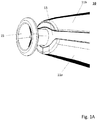
- FIG. 1 shows an exemplary electrical hand-held device 10, which is particularly suitable for domestic use.
- the Electric hand-held device 10 has a housing 11 to which a nozzle 15 can preferably be detachably fastened.
- Housing 11 and nozzle 15 can also be produced as an injection molded part.
- the housing 11 can essentially have the cross section of an "L" rotated by 180 °, the longer leg forming a handle part 11a and the shorter leg forming a housing part 11b to which the nozzle 15 can be detachably fastened.
- the housing part 11b can have a recess in which a translucent material 13 is arranged. The recess can run in a ring shape, so that the translucent material 13 forms a light ring.
- the translucent material 13 enables colored light treatment during a skin treatment, for example, by emitting blue light, which is generated by corresponding LEDs within the housing 11, from the light ring to the front, ie in the direction of the nozzle 15, onto the skin to be treated.
- the translucent material 13 forming a light ring also runs along the end face of the housing part 11b to which the nozzle 15 is attached.
- the nozzle 15 or its shaft preferably extends through an opening in the translucent material 13.
- a further recess can be provided in the housing part 11b, through which the keys of an operating panel 14, which is largely arranged in the housing 11, can be actuated.
- the control panel 14 can, for example, have two selection buttons with which two operating modes, for example a “pulse operation” or a “constant pressure flow operation”, can be set, and a button for switching the electrical hand-held device 10 on and off.
- the respective buttons can be used light-emitting components to provide optical support for the user.
- a recess for an energy supply connection 12 can be excluded in the bottom region of the handle part 11a.
- the power supply connection 12 can be designed as a DC socket to which, for example, an external 12 V DC plug-in power supply unit (not shown) can be connected to supply power to the electrical hand-held device 10.
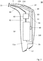
- Figure 2 shows that in Figure 1 Exemplary electrical hand-held device 10 shown with the housing 11 open.
- the nozzle 15 is preferably releasably attached to the end face of the housing 11 or the housing part 11b.
- An electrically controllable pump 50 is arranged in the housing 11 and is connected via a first pressure medium channel 31 to an electrically controllable valve 40, which is likewise arranged in the housing 11.
- the first pressure medium channel 31, which can be designed as a hose, for example, also runs within the housing 11.
- the electrically controllable valve 40 and the electrically controllable pump 50 are preferably accommodated in the handle part 11 a of the housing 11.
- a second pressure medium channel 30 is arranged in the housing 11, via which the nozzle 15 is connected to the electrically controllable valve 40.
- the second pressure medium channel 30, which in turn can be a hose, expediently runs in the housing part 11b.
- the second pressure medium channel 30 is made of a translucent material, so that the blue light emitted by the light-emitting components passes directly through the nozzle 15 onto the skin to be treated is directed.
- the second pressure medium channel 30 is designed as a translucent hose.
- a preferably DC-operated vibration motor 5 can be arranged in the housing part 11, which is designed to vibrate the nozzle 15 directly or indirectly.
- the vibration motor is arranged in the housing part 11b in such a way that it touches the nozzle or the second pressure medium channel 30 or the translucent material 13 forming the light ring and can thus set it in vibration.
- a control unit 110 is arranged in the housing 11, which is designed to control the valve 40, the vibration motor 5 and the pump 50.
- the control unit 110 is in particular designed to control the electrically controllable valve 40 in response to an operating mode selected on the control panel 14 in such a way that pressure pulses or an essentially constant pressure can be applied to the nozzle 15.
- the control unit 110 can be a microcontroller, for example.
- the control unit 110 can expediently carry out the function of a timer.
- parameters can be stored in the control unit 110 or in a separate memory (not shown) which define, for example, the duration of a pressure pulse and, for example, the duration of a treatment cycle, which can take a few minutes.
- the control unit 110 is able to control the electrically controllable valve 40 in such a way that pressure pulses at the nozzle 15 with a defined length and for a predetermined treatment time or a substantially constant pressure is applied for a predetermined treatment time.
- a temperature monitoring device 60 can be arranged in the housing 11, which is electrically connected to the control unit 110.
- the temperature monitoring device 60 is preferably arranged in the vicinity of the pump 50 in order to monitor its temperature.
- the temperature monitoring device 60 can be a temperature sensor that cyclically reports the measured temperature to the control unit 110, for example, which, in response to the temperature, can switch off the electrically controllable pump 50 and / or the electrically controllable valve 40 as soon as a predetermined temperature value is exceeded.
- the temperature monitoring device 60 can also be an automatically resetting temperature switch which is actuated when a predetermined temperature is exceeded, the actuation of the temperature switch being communicated to the control unit 110, which in turn then communicates with the electrically controllable pump 50 and / or the electrically controllable one Valve 40 can switch off.
- the control unit 110 can be designed to control the valve 40 by means of pulse width modulation.
- the electrically controllable pump 50, the electrically controllable valve 40, the vibration motor 5, the Temperature monitoring device 60 and control panel 14 are electrically connected to control unit 110.
- the hand-held device 10 has the energy supply connection 12.
- an external 12 V DC plug-in power supply unit (not shown) can be connected to the power supply connection 12, which is preferably designed as a DC socket.
- a printed circuit board 20 is arranged in the housing 11, preferably in the housing part 11b.
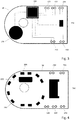
- the top of the printed circuit board 20, which preferably faces away from the bottom part of the housing 11, is shown in FIG Figure 3 shown, while the bottom of the circuit board 20, which faces the interior of the housing 11, in Figure 4 is shown.
- control unit 110 can be mounted on the top of the circuit board 20.
- Figure 3 shows, the printed circuit board 20, for example on the upper side, a first connection device 120 for the electrical connection of the electrically controllable valve 40, a second connection device 130 for the electrical connection of the electrically controllable pump 50, a third connection device 140 for the electrical energy supply of the hand-held device 10 and a further connection device 210 to connect the vibration motor 5.
- the first connection device 120 can have two connection points, both connection points being provided for connecting two supply lines which lead to the valve 40 as an electrical connection 90.
- the two connection points of the connection device 120 are each connected to the control unit 110 via a conductor track, as shown in FIG Figure 2 and Figure 3 you can see.
- connection device 210 preferably has two connection points for connecting two supply lines, which lead as an electrical connection to the electrically controllable vibration motor 5.
- the two connection points of the connection device 210 are each connected to the control unit 110 via a conductor track, as shown in FIG Figure 2 and Figure 3 you can see.
- the second connection device 130 preferably has two connection points for connecting two supply lines, which lead as an electrical connection 100 to the electrically controllable pump 50.
- the two connection points of the connection device 130 are each connected to the control unit 110 via a conductor track, as shown in FIG Figure 2 and Figure 3 you can see.
- the power supply connection 12 can be connected to the two connection points of the connection device 140 via two connection lines, which are provided with reference symbol 70.
- the two connection points of the connection device 140 are, for example, via a Fuse 150 and two interconnects are connected to control unit 110.
- a fourth connection device 160 can be provided on the printed circuit board, which again has two connection points, for example.
- the connection points of the connection device 160 can be connected via two connection lines which are shown in Figure 2 are identified by the reference symbol 80, connected to the temperature monitoring device 60 and via two conductor tracks to the control unit 110.
- a fifth connection device 180 can be provided on the printed circuit board 20 (see Fig. 4 ), to which the control panel 14 is electrically connected and which is connected to the control unit 110 via conductor tracks.
- an acoustic signal generator 170 can be arranged in the housing 11, which is preferably likewise arranged on the printed circuit board 20 and is connected to the control unit 110 via corresponding conductor tracks, as shown in FIG Figure 3 is shown.
- the control unit 110 is preferably designed to selectively supply a direct voltage present at the energy supply connection 12 to the connection device 120 for supplying energy to the electrically controllable valve 40, to the connection device 130 for supplying energy to the electrically controllable pump 50, to the connection device 160 for supplying energy to the temperature monitoring device 60 , to the connection device 180 for supplying energy to the control panel 14, to the connection device 210 for supplying energy to the vibration motor 5 and to the control acoustic signal generator 170.
- the components of the electrical hand-held device 10 are therefore not supplied with energy directly via an energy source connected to the energy supply connection 12, but indirectly via the control unit 110.
- an energy store 190 preferably a storage capacitor, can be arranged on the underside of the printed circuit board 20, which is connected to the control unit 110 via conductor tracks and can be charged via a direct voltage applied to the energy supply connection 12.
- the internal energy store 190 can be dimensioned such that, after the device has been automatically switched off by the control unit 110 and when a predetermined maximum operating time has been reached, the user prevents the device from being put back into operation immediately by the energy store 190, the control unit 110 and thus the timer can at least temporarily supply energy even when de-energized.
- a plurality of light-emitting components 200 which can be designed as LEDs, for example, can also be arranged.
- the light-emitting components 200 are preferably arranged in an approximately circular manner and preferably radiate the majority of the light in the direction of the interior of the housing 11, so that the light emitted by the light-emitting components 200 diffuses the translucent light ring 13 can be emitted to the outside and preferably focused in the direction of the nozzle 15.
- the light-emitting components 200 are connected to the control unit 110 via conductor tracks.
- the control unit 110 is designed, for example, to control the corresponding light-emitting components 200 as a function of the operating state or the selected operating mode or to connect it in a targeted manner to the energy supply connection 12.
- some of the light emitting devices 200 may emit red light and other light emitting devices 200 may emit blue light.
- the control unit 110 can, in particular, be designed to control the blue light-emitting components 200 during the treatment of the skin, and to control the red-light-emitting components 200 during an error, for example when the electrically controllable pump 50 overheats.
- various operating states or selected operating modes of the electrical hand-held device 10 can be visually signaled to the user under the control of the control unit 110.
- different operating states can be signaled to the user via the acoustic signal generator 170 and / or via the light-emitting components integrated in the respective buttons of the control panel 14.
- the control unit 110 ensures, for example, that the electrically controllable pump 50 and the blue-lit LEDs 200 are electrically connected to the power supply connection 12 and are thus supplied with current.
- the valve 40 is controlled by the control unit 110 in such a way that it generates pressure pulses of a defined length that are continuously generated for a predetermined treatment time.
- the control unit 110 establishes or interrupts the power supply to the valve 40 via the connecting line 90 in rhythm with the desired pressure pulses, and thus ensures that the valve 40 is opened and closed.
- control unit 110 can ensure, for example, that the vibration motor 5 is electrically connected to the energy supply connection 12 and is thus supplied with current.
- the vibration motor 5 now vibrates the nozzle 15.
- control unit 110 is connected to the power supply connection 12. It is now assumed that the temperature monitoring device 60 has been actuated because the temperature of the pump 50 has exceeded a critical value. In response to this, the control unit 110 separates the electrically controllable pump 50 and / or the electrically controllable valve 40 from the Power supply connection 12 and thus from the external power supply source. Depending on the implementation, the control unit 110 can be programmed in such a way that it can prevent the pump 50 and / or the valve 40 from being switched on again after switching off due to overheating before a sufficient cooling phase has elapsed, namely for example until the temperature switch is reset.
- control unit 110 can also monitor the maximum permissible, intended operating time of the device even when the electrical handheld device 10 is disconnected from the external energy supply source, even if only for a short time, for example, the internal energy store 190 can control unit 110 at least in a sufficient manner Supply energy to block immediate restart of the device by the user.
Landscapes
- Health & Medical Sciences (AREA)
- Biomedical Technology (AREA)
- Engineering & Computer Science (AREA)
- Life Sciences & Earth Sciences (AREA)
- Animal Behavior & Ethology (AREA)
- Veterinary Medicine (AREA)
- General Health & Medical Sciences (AREA)
- Public Health (AREA)
- Hematology (AREA)
- Anesthesiology (AREA)
- Heart & Thoracic Surgery (AREA)
- Vascular Medicine (AREA)
- Biophysics (AREA)
- Pathology (AREA)
- Nuclear Medicine, Radiotherapy & Molecular Imaging (AREA)
- Radiology & Medical Imaging (AREA)
- Surgical Instruments (AREA)
- Percussion Or Vibration Massage (AREA)
Applications Claiming Priority (1)
| Application Number | Priority Date | Filing Date | Title |
|---|---|---|---|
| DE102018127795.4A DE102018127795A1 (de) | 2018-11-07 | 2018-11-07 | Elektrisches Handgerät zum Einbringen von kosmetischen Präparaten in die Haut |
Publications (1)
| Publication Number | Publication Date |
|---|---|
| EP3662782A1 true EP3662782A1 (fr) | 2020-06-10 |
Family
ID=68470387
Family Applications (1)
| Application Number | Title | Priority Date | Filing Date |
|---|---|---|---|
| EP19207453.2A Withdrawn EP3662782A1 (fr) | 2018-11-07 | 2019-11-06 | Appareil portatif électrique permettant d'apporter des préparations cosmétiques dans la peau |
Country Status (2)
| Country | Link |
|---|---|
| EP (1) | EP3662782A1 (fr) |
| DE (1) | DE102018127795A1 (fr) |
Cited By (1)
| Publication number | Priority date | Publication date | Assignee | Title |
|---|---|---|---|---|
| WO2022198372A1 (fr) * | 2021-03-22 | 2022-09-29 | 上海茜茜纤美美容科技有限公司 | Dispositif d'injection de charge profonde dans la peau sans aiguille |
Families Citing this family (1)
| Publication number | Priority date | Publication date | Assignee | Title |
|---|---|---|---|---|
| WO2020138475A1 (fr) * | 2018-12-27 | 2020-07-02 | 株式会社ダイセル | Seringue sans aiguille |
Citations (5)
| Publication number | Priority date | Publication date | Assignee | Title |
|---|---|---|---|---|
| DE3115374A1 (de) * | 1981-04-16 | 1982-11-11 | Hoechst Ag, 6000 Frankfurt | Nadelloses injektionsgeraet |
| WO2004043533A2 (fr) * | 2002-11-12 | 2004-05-27 | Lothar Bode | Appareil a main d'injection sous pression destine a introduire des substances dans une zone de peau a traiter sous la pression d'un agent de pression gazeux ou liquide |
| WO2006086742A2 (fr) | 2005-02-09 | 2006-08-17 | Nanopharmatix, Inc. | Injecteur de microcourant |
| US20130218066A1 (en) * | 2012-02-17 | 2013-08-22 | Aptar France S.A.S. | Fluid dispenser |
| WO2014091035A1 (fr) * | 2012-12-15 | 2014-06-19 | Decaux Stéphane | Applicateur et capsule pour cet applicateur |
Family Cites Families (1)
| Publication number | Priority date | Publication date | Assignee | Title |
|---|---|---|---|---|
| DE20221228U1 (de) * | 2002-11-12 | 2005-07-07 | Bode, Lothar | Druckinjektions-Handgerät zum Einbringen von Substanzen unter Druck eines gasförmigen oder flüssigen Druckmittels in eine zu behandelnde Hautstelle |
-
2018
- 2018-11-07 DE DE102018127795.4A patent/DE102018127795A1/de not_active Withdrawn
-
2019
- 2019-11-06 EP EP19207453.2A patent/EP3662782A1/fr not_active Withdrawn
Patent Citations (6)
| Publication number | Priority date | Publication date | Assignee | Title |
|---|---|---|---|---|
| DE3115374A1 (de) * | 1981-04-16 | 1982-11-11 | Hoechst Ag, 6000 Frankfurt | Nadelloses injektionsgeraet |
| WO2004043533A2 (fr) * | 2002-11-12 | 2004-05-27 | Lothar Bode | Appareil a main d'injection sous pression destine a introduire des substances dans une zone de peau a traiter sous la pression d'un agent de pression gazeux ou liquide |
| DE10252917A1 (de) | 2002-11-12 | 2004-05-27 | Lothar Bode | Druckinjektions-Handgerät zum Einbringen von Substanzen unter Druck eines gasförmigen oder flüssigen Druckmittels in eine zu behandelnde Hautstelle |
| WO2006086742A2 (fr) | 2005-02-09 | 2006-08-17 | Nanopharmatix, Inc. | Injecteur de microcourant |
| US20130218066A1 (en) * | 2012-02-17 | 2013-08-22 | Aptar France S.A.S. | Fluid dispenser |
| WO2014091035A1 (fr) * | 2012-12-15 | 2014-06-19 | Decaux Stéphane | Applicateur et capsule pour cet applicateur |
Cited By (1)
| Publication number | Priority date | Publication date | Assignee | Title |
|---|---|---|---|---|
| WO2022198372A1 (fr) * | 2021-03-22 | 2022-09-29 | 上海茜茜纤美美容科技有限公司 | Dispositif d'injection de charge profonde dans la peau sans aiguille |
Also Published As
| Publication number | Publication date |
|---|---|
| DE102018127795A1 (de) | 2020-05-07 |
Similar Documents
| Publication | Publication Date | Title |
|---|---|---|
| EP3524317B1 (fr) | Appareil pouvant être tenu dans la main destiné au traitement de la peau assisté électriquement | |
| EP1991195B1 (fr) | Appareil manuel pour des soins combinés du visage | |
| AT17022U1 (fr) | ||
| DE202013010173U1 (de) | Tragbares Dermaplaning-Gerät | |
| DE202007019063U1 (de) | Vorrichtung zur nicht-invasiven Behandlung von Hautgewebe | |
| WO2008046671A1 (fr) | Système, dispositif et procédé de traitement antibactérien et fongicide d'un corps humain ou animal | |
| WO2008043520A2 (fr) | Dispositif de traitement dermatologique | |
| EP3662782A1 (fr) | Appareil portatif électrique permettant d'apporter des préparations cosmétiques dans la peau | |
| EP1269966A2 (fr) | Partie pour traitement ou de massage de pied et appareil de traitement de pied avec une telle partie | |
| DE9417441U1 (de) | Farblicht-Behandlungsgerät | |
| EP4230250A1 (fr) | Dispositif manuel de micronedding pour percer localement la peau et articles | |
| DE10210268A1 (de) | Kopfhautmassagegerät | |
| EP1638648A2 (fr) | Dispositif d'acuponcture faisant appel a un rayon laser | |
| DE10128629A1 (de) | Hautpflaster, Licht bzw. Strahlung emittierende Vorrichtung hierfür, sowie Verfahren zur Anhebung des menschlichen Wohlbefindens | |
| WO2004043533A2 (fr) | Appareil a main d'injection sous pression destine a introduire des substances dans une zone de peau a traiter sous la pression d'un agent de pression gazeux ou liquide | |
| WO1990006153A1 (fr) | Appareil d'iontophorese | |
| DE602004008661T2 (de) | Gerät zur beleuchtung einer zone von säugetierhaut | |
| KR102016559B1 (ko) | 피부용 약물 주입기 | |
| EP1423164A1 (fr) | Appareil d'irradiation dote d'une diode electroluminescente et d'un guide de lumiere | |
| EP4245283B1 (fr) | Appareil portatif de micro-aiguillage permettant de stimuler localement la peau, dispositif de stimulation de la peau et article | |
| DE3421750A1 (de) | Therapeutische vorrichtung unter anwendung von fluessigkeitsstroemen | |
| EP3880056A1 (fr) | Procédé et appareil pour exécuter différentes fonctions associées à des appareils chirurgicaux | |
| KR101431802B1 (ko) | 치과용 시린지의 제어밸브 | |
| DE102020123082B4 (de) | Gesichtsverschönerungs- und -pflegevorrichtung | |
| EP2954912A1 (fr) | Module pour un appareil portatif destiné à introduire une substance à travers la surface de la peau, article et agencement |
Legal Events
| Date | Code | Title | Description |
|---|---|---|---|
| PUAI | Public reference made under article 153(3) epc to a published international application that has entered the european phase |
Free format text: ORIGINAL CODE: 0009012 |
|
| AK | Designated contracting states |
Kind code of ref document: A1 Designated state(s): AL AT BE BG CH CY CZ DE DK EE ES FI FR GB GR HR HU IE IS IT LI LT LU LV MC MK MT NL NO PL PT RO RS SE SI SK SM TR |
|
| AX | Request for extension of the european patent |
Extension state: BA ME |
|
| STAA | Information on the status of an ep patent application or granted ep patent |
Free format text: STATUS: THE APPLICATION HAS BEEN WITHDRAWN |
|
| 18W | Application withdrawn |
Effective date: 20201110 |