EP3662846A1 - Instrument à demeure in vivo, système de pose d'instrument à demeure in vivo et procédé de fabrication d'instrument à demeure in vivo - Google Patents
Instrument à demeure in vivo, système de pose d'instrument à demeure in vivo et procédé de fabrication d'instrument à demeure in vivo Download PDFInfo
- Publication number
- EP3662846A1 EP3662846A1 EP18841280.3A EP18841280A EP3662846A1 EP 3662846 A1 EP3662846 A1 EP 3662846A1 EP 18841280 A EP18841280 A EP 18841280A EP 3662846 A1 EP3662846 A1 EP 3662846A1
- Authority
- EP
- European Patent Office
- Prior art keywords
- coil
- wire
- vivo indwelling
- indwelling instrument
- resin tip
- Prior art date
- Legal status (The legal status is an assumption and is not a legal conclusion. Google has not performed a legal analysis and makes no representation as to the accuracy of the status listed.)
- Pending
Links
Images

Classifications
-
- A—HUMAN NECESSITIES
- A61—MEDICAL OR VETERINARY SCIENCE; HYGIENE
- A61B—DIAGNOSIS; SURGERY; IDENTIFICATION
- A61B17/00—Surgical instruments, devices or methods
- A61B17/12—Surgical instruments, devices or methods for ligaturing or otherwise compressing tubular parts of the body, e.g. blood vessels or umbilical cord
- A61B17/12022—Occluding by internal devices, e.g. balloons or releasable wires
- A61B17/12131—Occluding by internal devices, e.g. balloons or releasable wires characterised by the type of occluding device
- A61B17/1214—Coils or wires
- A61B17/12154—Coils or wires having stretch limiting means
-
- A—HUMAN NECESSITIES
- A61—MEDICAL OR VETERINARY SCIENCE; HYGIENE
- A61B—DIAGNOSIS; SURGERY; IDENTIFICATION
- A61B17/00—Surgical instruments, devices or methods
- A61B17/12—Surgical instruments, devices or methods for ligaturing or otherwise compressing tubular parts of the body, e.g. blood vessels or umbilical cord
- A61B17/12022—Occluding by internal devices, e.g. balloons or releasable wires
- A61B17/12099—Occluding by internal devices, e.g. balloons or releasable wires characterised by the location of the occluder
- A61B17/12109—Occluding by internal devices, e.g. balloons or releasable wires characterised by the location of the occluder in a blood vessel
- A61B17/12113—Occluding by internal devices, e.g. balloons or releasable wires characterised by the location of the occluder in a blood vessel within an aneurysm
-
- A—HUMAN NECESSITIES
- A61—MEDICAL OR VETERINARY SCIENCE; HYGIENE
- A61B—DIAGNOSIS; SURGERY; IDENTIFICATION
- A61B17/00—Surgical instruments, devices or methods
- A61B17/12—Surgical instruments, devices or methods for ligaturing or otherwise compressing tubular parts of the body, e.g. blood vessels or umbilical cord
- A61B17/12022—Occluding by internal devices, e.g. balloons or releasable wires
- A61B17/12131—Occluding by internal devices, e.g. balloons or releasable wires characterised by the type of occluding device
- A61B17/1214—Coils or wires
- A61B17/12145—Coils or wires having a pre-set deployed three-dimensional shape
-
- A—HUMAN NECESSITIES
- A61—MEDICAL OR VETERINARY SCIENCE; HYGIENE
- A61B—DIAGNOSIS; SURGERY; IDENTIFICATION
- A61B17/00—Surgical instruments, devices or methods
- A61B2017/00526—Methods of manufacturing
-
- A—HUMAN NECESSITIES
- A61—MEDICAL OR VETERINARY SCIENCE; HYGIENE
- A61B—DIAGNOSIS; SURGERY; IDENTIFICATION
- A61B17/00—Surgical instruments, devices or methods
- A61B17/12—Surgical instruments, devices or methods for ligaturing or otherwise compressing tubular parts of the body, e.g. blood vessels or umbilical cord
- A61B17/12022—Occluding by internal devices, e.g. balloons or releasable wires
- A61B2017/1205—Introduction devices
- A61B2017/12054—Details concerning the detachment of the occluding device from the introduction device
-
- A—HUMAN NECESSITIES
- A61—MEDICAL OR VETERINARY SCIENCE; HYGIENE
- A61B—DIAGNOSIS; SURGERY; IDENTIFICATION
- A61B90/00—Instruments, implements or accessories specially adapted for surgery or diagnosis and not covered by any of the groups A61B1/00 - A61B50/00, e.g. for luxation treatment or for protecting wound edges
- A61B90/39—Markers, e.g. radio-opaque or breast lesions markers
- A61B2090/3966—Radiopaque markers visible in an X-ray image
-
- A—HUMAN NECESSITIES
- A61—MEDICAL OR VETERINARY SCIENCE; HYGIENE
- A61B—DIAGNOSIS; SURGERY; IDENTIFICATION
- A61B90/00—Instruments, implements or accessories specially adapted for surgery or diagnosis and not covered by any of the groups A61B1/00 - A61B50/00, e.g. for luxation treatment or for protecting wound edges
- A61B90/90—Identification means for patients or instruments, e.g. tags
- A61B90/92—Identification means for patients or instruments, e.g. tags coded with colour
Definitions
- the present invention relates to an in-vivo indwelling instrument for vascular embolization at a vascular disease site in a blood vessel, an in-vivo indwelling instrument delivering system and a method for producing an in-vivo indwelling instrument.
- an in-vivo indwelling instrument for embolization is indwelled at a target site to promote the thrombogenesis, thereby preventing a rupture of the aneurysm, for example.
- Patent Literatures 1 to 4 disclose an in-vivo indwelling instrument for embolization including a coil, a stretch resistant member provided in the coil, and a tip provided at a distal end part of the coil.
- the in-vivo indwelling instrument is attached to a tip end part of a pusher, and pushed by the pusher toward a distal side of a catheter or the like that is used when the instrument is indwelled, whereby the in-vivo indwelling instrument is delivered to a target site in the body, such as the aneurysm.
- the stretch resistant member may possibly stray from the coil when the in-vivo indwelling instrument is pushed by a pusher, which may make it impossible for the indwelling instrument to be delivered to a target site. Furthermore, only a tip may possibly remain in a blood vessel when a coil is removed under constraint during a procedure.
- an object of the present invention to provide an in-vivo indwelling instrument in which a stretch resistant member at a distal end part of a coil does not easily stray from the coil, a delivering system for the in-vivo indwelling instrument, and a method for producing the in-vivo indwelling instrument.
- An in-vivo indwelling instrument which is able to achieve the above object includes: a coil that is formed by winding a wire and extends in a distal and proximal direction; a resin tip that is connected to a distal end part of the coil; and a stretch resistant member that is provided in a lumen of the coil and is connected to the resin tip.
- the coil includes a contacting part which is in the distal end part of the coil and is a part of the wire where adjacent wires are in contact with each other by a length of at least one round or more, and a separating part which is placed on a proximal side of the contacting part and is a part of the wire where adjacent wires are not in contact, and a part of the resin tip is placed in the separating part.
- the in-vivo indwelling instrument of the present invention since the part of the resin tip is placed in the separating part, the coil is firmly fixed with the resin tip. Therefore, it is possible to inhibit the resin tip or the stretch resistant member from straying from the coil when the in-vivo indwelling instrument is pushed by a pusher. Furthermore, since it is possible to visually recognize that the part of the resin tip exists in the separating part, it is possible to easily grasp a fixed state between the separating part and the resin tip.
- the part of the resin tip is preferably sandwiched between the adjacent wires of the separating part.
- the part of the resin tip is preferably placed inside the coil at the separating part.
- the separating part is preferably placed at a second pitch or more and tenth pitch or less from a distal end of the coil.
- the part of the resin tip preferably has a color that is different from a color of the coil at the separating part.
- the resin tip preferably includes a material that changes a color by light irradiation.
- the stretch resistant member is preferably connected to the resin tip through the coil distal to the separating part.
- a part of the wire exists within a central region surrounded by a circle having a diameter of half a maximum outer diameter of the coil and having a center that is a middle point of the maximum outer diameter, and the stretch resistant member is preferably connected to the resin tip through a connecting part which is the part of the wire.
- an in-vivo indwelling instrument delivering system which is able to achieve the above object includes: an in-vivo indwelling instrument including a coil that is formed by winding a wire and extends in a distal and proximal direction, a resin tip that is connected to a distal end part of the coil, and a stretch resistant member that is provided in a lumen of the coil and is connected to the resin tip; and a sheath that stores the coil in a lumen thereof. When the coil is provided in the sheath, the resin tip is in contact with an inner wall of the sheath. According to the in-vivo indwelling instrument delivering system of the present invention, it is possible to secure the flexibility of the distal end part of the in-vivo indwelling instrument.
- an in-vivo indwelling instrument delivering system which is able to achieve the above object includes: an in-vivo indwelling instrument including a coil that is formed by winding a wire and extends in a distal and proximal direction, a resin tip that is connected to a distal end part of the coil, and a stretch resistant member that is provided in a lumen of the coil and is connected to the resin tip; and a sheath that stores the coil in a lumen thereof.
- the resin tip is in contact with an inner wall of the sheath.
- the resin tip in a case of pushing the coil to take out the resin tip from the sheath, the resin tip is in contact with a distal end part of the sheath.
- a method for producing an in-vivo indwelling instrument which is able to achieve the above object includes: preparing a coil formed by winding a wire, and a wire-shaped member having a folded part to which a stretch resistant member is connected; forming a separating part in the coil by making wider an interval between adjacent wires of the coil; inserting the folded part of the wire-shaped member into a lumen of the coil; inserting a tubular member into the lumen of the coil; heating the tubular member; and heating the wire-shaped member.
- the method for producing an in-vivo indwelling instrument of the present invention since a part of the tubular member that is heated is melted to flow into the separating part of the coil, it is possible to manufacture an in-vivo indwelling instrument in which the coil is firmly fixed with the resin tip. Furthermore, by providing the separating part in the coil, it is possible to inhibit a resin from flowing on a proximal side of the separating part owing to the capillary phenomenon. This makes it possible to secure the flexibility of the distal end part of the in-vivo indwelling instrument.
- the tubular member is preferably heated in a state of making wider the interval between adjacent wires of the coil on a proximal side of the separating part.
- the tubular member and the wire-shaped member are preferably heated in a same heating step.
- the in-vivo indwelling instrument of the present invention since the part of the resin tip is placed in the separating part, the coil is firmly fixed with the resin tip. Therefore, it is possible to inhibit the resin tip or the stretch resistant member from straying from the coil. Furthermore, since it is possible to visually recognize that the part of the resin tip exists in the separating part, it is possible to easily grasp a fixed state between the separating part and the resin tip.
- the in-vivo indwelling instrument delivering system of the present invention it is possible to secure the flexibility of the distal end part of the in-vivo indwelling instrument.
- the method for producing an in-vivo indwelling instrument of the present invention since a part of the tubular member that is heated is melted to flow into the separating part of the coil, it is possible to manufacture an in-vivo indwelling instrument in which the coil is firmly fixed with the resin tip. Furthermore, by providing the separating part in the coil, it is possible to inhibit a resin from flowing on a proximal side of the separating part owing to the capillary phenomenon. This makes it possible to secure the flexibility of the distal end part of the in-vivo indwelling instrument.
- An in-vivo indwelling instrument includes: a coil that is formed by winding a wire and extends in a distal and proximal direction; a resin tip that is connected to a distal end part of the coil; and a stretch resistant member that is provided in a lumen of the coil and is connected to the resin tip.
- the coil includes a contacting part which is in the distal end part of the coil and is a part of the wire where adjacent wires are in contact with each other by a length of at least one round or more, and a separating part which is placed on a proximal side of the contacting part and is a part of the wire where adjacent wires are not in contact, and a part of the resin tip is placed in the separating part.
- the in-vivo indwelling instrument of the present invention since the part of the resin tip is placed in the separating part, the coil is firmly fixed with the resin tip. Therefore, it is possible to inhibit the resin tip or the stretch resistant member from straying from the coil when the in-vivo indwelling instrument is pushed by a pusher. Furthermore, since it is possible to visually recognize that the part of the resin tip exists in the separating part, it is possible to easily grasp a fixed state between the separating part and the resin tip.
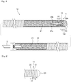
- Fig. 1 is a cross-sectional view (a partial side view) of an in-vivo indwelling instrument according to an embodiment of the present invention.
- Fig. 2 is an enlarged side view of a distal side of the in-vivo indwelling instrument illustrated in Fig. 1 .
- the in-vivo indwelling instrument includes a distal side and a proximal side.
- the proximal side of the in-vivo indwelling instrument indicates a side in a direction toward a user's (operator's) hand with respect to an extending direction of the in-vivo indwelling instrument
- the distal side indicates a side in a direction opposite to the proximal side (i.e., in a direction toward a procedure target).
- a direction from the proximal side to the distal side of the in-vivo indwelling instrument is referred to as an axial direction or a distal and proximal direction.
- the in-vivo indwelling instrument 10 includes a coil 11 that is formed by winding a wire 12 and extends in the distal and proximal direction, a resin tip 20 that is connected to a distal end part of the coil 11, and a stretch resistant member 21 that is provided in a lumen of the coil 11.
- the part at which the wire 12 is wound into a coil shape is referred to as the coil 11.
- the coil 11 is formed by one or a plurality of wires 12 being wound spirally, and is, for example, a secondary coil formed by a primary coil, which is formed by the wires 12 being wound spirally, being further wound, for example, spirally or in a three-dimensional shape, around the primary coil.
- a secondary coil formed by a primary coil which is formed by the wires 12 being wound spirally, being further wound, for example, spirally or in a three-dimensional shape, around the primary coil.
- the coil 11 is illustrated in a manner that the secondary coil is extended linearly for the purpose of easy understanding of the shape of the primary coil.
- the density (winding interval) of the coil 11 is not specifically limited, and the coil 11 can be formed by tight winding, pitch winding, or a combination thereof.
- the state in which the parts of the wire 12 that are adjacent to each other in the distal and proximal direction are in contact with each other is referred to as the tight winding
- the state in which the parts of the wire 12 that are adjacent to each other in the distal and proximal direction are not in contact with each other is referred to as the pitch winding.
- Such a state of not being in contact with each other refers to a state in which the parts of the wire 12 that are adjacent to each other in the distal and proximal direction are separated from each other.
- the wire 12 forming the coil 11 preferably has bio-compatibility and flexibility, and is, for example, more preferably made of metal materials such as platinum, gold, titanium, tungsten, and alloys thereof, and stainless steel, and is yet more preferably made of, namely, a platinum-tungsten alloy.
- the cross-sectional shape of the wire 12 forming the coil 11 in the axial direction may be circle, ellipse, polygon, or a combination thereof.
- the coil 11 may be a single-layer coil, or alternatively, may be a multi-layer coil having a plurality of layers.
- a chemical may be applied to at least either one of the coil 11, the wire 12, and the stretch resistant member 21.
- the outer diameter of the wire 12 forming the coil 11 is not particularly limited, and, for example, may be 25 pm or more, 30 pm or more, or 35 pm or more, and even may be 75 pm or less or 70 pm or less, as an acceptable outer diameter.
- the wire 12 may be a single wire-shaped member from one end to the other end, or alternatively, may be provided by a plurality of wire-shaped members being coupled to each other.
- the resin tip 20 is connected to the distal end part of the coil 11, and a member that covers the distal end part of the coil 11 to prevent the tip end 12a of the wire 12 from being in direct contact with the inner wall of a blood vessel.
- the shape of the resin tip 20 is not particularly limited, but can be formed in, for example, a hemispherical shape, a semi-ellipse spherical shape, columnar shape, or polygonal pillar shape.
- the resin tip 20 is preferably made of a thermoplastic resin or an ultraviolet curing resin, for example, epoxy acrylate resin, urethane acrylate resin, or polyester acrylate resin can be used.
- the viscosity of a resin constituting the resin tip 20 may be 10 mPa ⁇ s or more, 50 mPa ⁇ s or more, or 100 mPa ⁇ s or more, and even may be 2000 mPa ⁇ s or less, 1500 mPa ⁇ s or less, or 1000 mPa ⁇ s or less, as an acceptable viscosity.
- the melt flow rate of a resin constituting the resin tip 20 may be 0.1 g/min or more, 1 g/min or more, 10 g/min or more, or 25 g/min or more, and may also be 100 g/min or less, 75 g/min or less, or 50 g/min or less, as a melt flow rate.
- the resin easily flows between parts of the wire 12 of the contacting part 13 of the coil 11 described later, and thus, it is possible to inhibit the resin from flowing into the proximal side of the separating part 14.
- the outer diameter of the resin tip 20 is preferably larger than the inner diameter of the coil 11. Furthermore, in order to prevent the resin tip 20 from straying from the coil 11, a part of the resin tip 20 is preferably placed in the lumen of the coil 11, and is more preferably inserted into the lumen of the distal end part of the coil 11.
- the proximal end of the resin tip 20 is preferably disposed more distally than the position having a length of one tenth of the entire length of the coil 11 from the distal end of the coil 11 toward the proximal side, more preferably disposed more distally than the position having a length of one fifteenth, and yet more preferably disposed more distally than the position having a length of one twentieth.
- the resin tip 20 is preferably joined with an inner surface of the coil 11.
- the resin tip 20 preferably exists closer to the proximal side than the tip end 12a of the wire 12. Since the resin tip 20 is fixed firmly to the coil 11, it is possible to inhibit the resin tip 20 from straying from the coil 11.
- the resin tip 20 preferably extends more distally than the distal end of the coil 11.
- a part extending more distally than the distal end of the coil 11 is assumed as a tip end part 20a of the resin tip 20.
- the tip end part 20a of the resin tip 20 preferably has a size that is two times or more the outer diameter of the wire 12 in the axial direction, more preferably three times or more, yet more preferably four times or more, or has a size that is seven times or less or six times or less, as an acceptable size.
- the stretch resistant member 21 is provided in a lumen of the coil 11 and is connected to the resin tip 20.
- the stretch resistant member 21 is a wire-shaped member that inhibits the coil 11 from extending in the axial direction during the operation of the in-vivo indwelling instrument 10.
- the stretch resistant member 21 may be a single wire or a stranded wire.
- the stretch resistant member 21 may has a single layer or may be a multi-layer body having a plurality of layers.
- the stretch resistant member 21 may include an inner layer made of a stranded wire having a plurality of wires 12 and an outer layer located on the outer side of the inner layer and including resin composition.
- a single piece or a plurality of pieces of the stretch resistant member 21 may be provided in the coil 11.
- the stretch resistant member 21 is preferably made of resin or a metal material.
- the metal material include platinum, gold, rhodium, palladium, rhenium, gold, silver, titanium, tantalum, tungsten and alloys thereof, and stainless steel
- the resin material include polyester resin such as polyethylene terephthalate, polyamide resin such as nylon, polyolefin resin such as polyethylene, polypropylene, and the like.
- the stretch resistant member 21 can increase flexibility and improve the delivery performance of the in-vivo indwelling instrument 10.
- the stretch resistant member 21 made of resin is not ruptured due to metal fatigue during delivery, and can mitigate stretching by the end part of the coil 11 extending linearly due to the insufficient length of the stretch resistant member 21 when the coil 11 is provided in an aneurysm.
- the stretch resistant member 21 may be made of a material different from the coil 11.
- the coil 11 is preferably made of a platinum-tungsten alloy, and the stretch resistant member 21 is preferably made of polypropylene resin.
- the cross-sectional shape of the stretch resistant member 21 in the axial direction may be circle, ellipse, polygon, or a combination thereof.
- the outer diameter of the stretch resistant member 21 suffices as long as it is smaller than a lumen of the coil 11.
- the stretch resistant member 21 is preferably provided in the lumen of the coil 11 in a state being folded back. Therefore, the outer diameter of the stretch resistant member 21 is preferably smaller than one second an inner diameter of the coil 11, and more preferably one third or less.
- the outer diameter of the stretch resistant member 21 is preferably one fifteenth or more the inner diameter of the coil 11, and more preferably, one tenth or more.
- the outer diameter of the stretch resistant member 21 may be, for example, 20 pm or more, 25 pm or more, or 40 pm or less, or 35 pm or less.
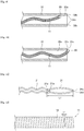
- the stretch resistant member 21 preferably has a linear shape, a wave shape, or a spiral shape, and more preferably has the wave shape. This makes it possible to smoothly indwell the stretch resistant member 21 until the end of the coil 11 and secure the length of the stretch resistant member 21 in the interior of the coil 11. Therefore, it is possible to mitigate a phenomenon of stretching by the end part of the coil 11 extending linearly due to the insufficient length of the stretch resistant member 21 can be mitigated when the in-vivo indwelling instrument 10 is indwelled at a target site during treatment.
- the stretch resistant member 21 has a wave shape
- the amplitude of the wave is preferably equal to or larger than the outer diameter of the wire 12.
- the amplitude of the wave of the stretch resistant member 21 may be 25 pm or more, 30 pm or more, or 40 pm or more, or may be 100 pm or less, 80 pm or less, or 60 pm or less.
- the coil 11 includes a contacting part 13 which is the distal end part and in which parts of the wire 12 that are adjacent to each other are in contact with each other by a length of at least one round or more, and a separating part 14 (first separating part 14) which is located on a proximal side of the contacting part 13 and at which the parts of the wire 12 that are adjacent to each other are separated from each other.
- a part of the resin tip 20 is placed in the separating part 14. According to the in-vivo indwelling instrument 10 of the present invention, since the part of the resin tip 20 exists in the separating part 14, the coil 11 is firmly fixed with the resin tip 20.
- the parts of the wire 12 that are adjacent to each other at the contacting part 13 are preferably in contact with each other by the length of 1.5 rounds or more, more preferably 2 rounds or more, yet more preferably 3 rounds or more, and further yet more preferably 4 rounds or more. Furthermore, in order to secure the flexibility at the distal end part of the in-vivo indwelling instrument 10 by forming the contacting part 13 to be short in the axial direction, the parts of the wire 12 that are adjacent to each other at the contacting part 13 are preferably in contact with each other by the length of 10 rounds or less, more preferably 8 rounds or less, and yet more preferably 5 rounds or less.
- the contacting part 13 is preferably provided at a part including the distal end of the coil 11, but the contacting part 13 may also be provided on the proximal side of the distal end.
- One or a plurality of separating parts 14 may be provided, but one separating part 14 is preferably provided. With such a configuration, it is possible to inhibit the resin tip 20 from being made excessively long in the axial direction, and thus, it is possible to secure the flexibility at the distal end part of the in-vivo indwelling instrument 10.
- the length of the separating part 14 in the axial direction is preferably half or more the outer diameter of the wire 12, more preferably equal to or larger than the outer diameter of the wire 12, and yet more preferably 1.5 times or more the outer diameter of the wire 12. This makes it possible to securely fix the resin tip 20 and the coil 11. Meanwhile, the length of the separating part 14 in the axial direction is preferably three times or less the outer diameter of the wire 12, more preferably 2.5 times or less the outer diameter of the wire 12. With such a configuration, it is possible to inhibit the resin tip 20 from being made excessively long in the axial direction, and thus, it is possible to secure the flexibility of the distal end part of the in-vivo indwelling instrument 10.
- the position of the separating part 14 is not particularly limited in the axial direction, but the separating part 14 is preferably placed at a second pitch or more from the distal end of the coil 11, more preferably third pitch or more from the distal end, and yet more preferably fourth pitch or more from the distal end. Furthermore, the separating part 14 is preferably placed at a tenth pitch or less from the distal end of the coil 11, more preferably eighth pitch or less from the distal end, and yet more preferably sixth pitch or less from the distal end. Providing the separating part 14 at such a position makes it possible to firmly fix the coil 11 and the resin tip 20, and to secure the flexibility of the distal end part of the in-vivo indwelling instrument 10.
- the part of the resin tip 20 is preferably sandwiched between the adjacent wires 12 of the separating part 14. Since the part of the resin tip 20 is sandwiched between the adjacent wires 12 in this way, the resin tip 20 is firmly fixed to the coil 11. From the viewpoint of further fixing the coil 11 and the resin tip 20 firmly, at the separating part 14, the part of the resin tip 20 is preferably sandwiched in the range that is equal to or larger than the radius of the wire 12, of which the parts are adjacent to each other, in the radial direction, and more preferably three-fourths of the diameter of the wire 12.
- the part of the resin tip 20 is preferably sandwiched in the range that is equal to or smaller than the diameter of the wire 12, of which the parts are adjacent to each other, and the resin tip 20 is preferably placed inside the outer diameter of the coil 11.
- the fixing between the resin tip 20 and the coil 11 are made firmer.
- the part of the resin tip 20 is placed from the outer side, in the radial direction, of the parts of the wire 12 that are adjacent to each other at the separating part 14 over the separating part 14, the fixing is also made firmer.
- the part of the resin tip 20 is preferably placed inside the coil 11 at the separating part 14. By providing the resin tip 20 in this way, the coil 11 and the resin tip 20 can be fixed firmly.
- the part of the resin tip 20 is preferably placed inside the coil 11 on the distal side of the proximal end of the separating part 14.
- the part of the resin tip 20 is preferably placed inside the coil 11 on the proximal side of the proximal end of the separating part 14. By providing the resin tip 20 in this way, the coil 11 and the resin tip 20 can be fixed further firmly.
- the part of the resin tip 20 preferably has a different color from the coil 11 at the separating part 14.
- the difference in color between the part of the resin tip 20 and the coil 11 means that at least one of hue, brightness, and chroma defined according to JIS Z8721 differs. Since the part of the resin tip 20 has a different color from the coil 11, the fixed state between the part of the resin tip 20 and the coil 11 is visually recognized readily at the time of producing the in-vivo indwelling instrument 10.
- the coil 11 is preferably made of a metal material such as platinum-tungsten, in a case in which the color of the coil 11 is silvery-white, for example, the brightness can be differentiated by changing the color of the resin tip 20 into a different color from the coil 11, such as blue.
- the resin tip 20 preferably includes a material that changes its color by light irradiation.
- a material that changes its color by light irradiation a color-changing fluorescent material having CaF 2 (fluorite) or rare earth, for example, as a main raw material can be used.
- a material that changes its color by light irradiation a material in which a photopolymerization initiator or a photosensitizer are contained in a resin material such as epoxy acrylate resin, urethane acrylate resin, or polyester acrylate resin can be used.
- a material is also colored by light irradiation and not colored without light irradiation, and thus, can be preferably used as a material that changes its color by light irradiation.
- a method for connecting the coil 11 and the stretch resistant member 21 will be described.
- the stretch resistant member 21 and the coil 11 are connected through the resin tip 20.
- a mooring part 20b that hooks a part of the stretch resistant member 21 is preferably provided at the resin tip 20.
- the shape of the mooring part 20b is not particularly limited as long as the mooring part 20b can connect the stretch resistant member 21, and for example, can be a loop shape or a hook shape. This makes it possible to simplify the producing process of the in-vivo indwelling instrument 10.
- the stretch resistant member 21 includes a folded part 21a that is folded back in the distal and proximal direction, and the folded part 21a is preferably connected to the mooring part 20b of the resin tip 20. Specifically, the folded part 21a of the stretch resistant member 21 is preferably hooked at the mooring part 20b of the resin tip 20. With such a configuration, the stretch resistant member 21 and the resin tip 20 can be readily connected to each other. This makes it possible to simplify the producing process of the in-vivo indwelling instrument 10.
- the stretch resistant member 21 is preferably fixed to a proximal end part of the coil 11 as well.
- the stretch member 21 and the proximal end part of the coil 11 can be connected and fixed to each other by, for example, a physically fixing method such as deposition, welding, clamping such as calking, adhesion by an adhesive, engaging, coupling, binding, knotting, or a combination thereof.
- the stretch resistant member 21 can also be fixed to a connecting part of the coil 11 and a pusher or a detachment part 2, in addition to the proximal end part of the coil 11.
- the proximal end part of the stretch resistant member 21 and the distal end part of the detachment part 2 are bound together.
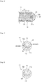
- FIG. 3 is a cross-sectional view (a partial side view) of another in-vivo indwelling instrument 10 according to an embodiment of the present invention.
- Fig. 4 is a front view of the coil 11 of the in-vivo indwelling instrument 10 illustrated in Fig. 3 .
- the stretch resistant member 21 is preferably connected to the resin tip 20 through the coil 11 distal to the separating part 14.
- the stretch resistant member 21 is connected not only to the resin tip 20 but also to the coil 11, it is possible to inhibit the stretch resistant member 21 from straying from the coil 11 when performing a pushing operation of the coil 11 by the pusher part 3.
- the parts of the stretch resistant member 21 and the coil 11 are preferably buried in the resin tip 20.
- the coil 11 is preferably connected directly to the stretch resistant member 21 on the distal side of the separating part 14. This further inhibits the stretch resistant member 21 from straying from the coil 11.
- a method for connecting the stretch resistant member 21 and the coil 11 on the distal side of the separating part 14 a method similar to a method for connecting the proximal end part of the coil 11 and the stretch resistant member 21 can be used.
- a part of the wire 12 exists within a central region 15 surrounded by a circle having a diameter of half the maximum outer diameter of the coil 11 and having a center that is the middle point 11a of the maximum outer diameter
- the stretch resistant member 21 is preferably connected to the connecting part 25 which is the part of the wire 12 existing within the central region 15.
- the stretch resistant member 21 is preferably connected to the resin tip 20 through the connecting part 25. Since the connecting part 25 of the wire 12 is connected to the stretch resistant member 21 in this way, it is possible to inhibit the stretch resistant member 21 from straying from the coil 11 when the in-vivo indwelling instrument 10 is pushed by a pusher part 3.
- the connecting part 25 of the wire 12 exists within the central region 15, the stretch resistant member 21 that is connected to the connecting part 25 is also readily provided in the central region 15. This allows the function of inhibiting the stretch resistant member 21 from extending in the axial direction of the coil 11 to be effectively exerted.
- the coil 11 and the connecting part 25 are formed by the same wire 12.
- the coil 11 is a part at which the wire 12 is wound in a coil shape
- the connecting part 25 is a part of the wire 12.
- the connecting part 25 is disposed more distally than the middle point in the distal and proximal direction.
- the connecting part 25 is preferably disposed on the distal side of the coil 11. Specifically, the proximal end of the connecting part 25 is preferably disposed more distally than the position having a length of one tenth of the entire length of the coil 11 from the distal end of the coil 11 toward the proximal side, more preferably disposed more distally than the position having a length of one fifteenth, and yet more preferably disposed more distally than the position having a length of one twentieth..
- the connecting part 25 of the coil 11 may be provided on the distal side of the distal end of the separating part 14, or may be provided on the proximal side thereof. In order to bury the connecting part 25 of the coil 11 in the resin tip 20, the connecting part 25 of the coil 11 is preferably provided on the distal side of the distal end of the separating part 14.
- the stretch resistant member 21 includes a folded part 21a that is folded back in the distal and proximal direction, and the folded part 21a is preferably connected to the connecting part 25 of the wire 12.
- the folded part 21a of the stretch resistant member 21 is more preferably hooked at the connecting part 25 of the wire 12.
- the shape of the connecting part 25 of the wire 12 is not particularly limited.
- the connecting part 25 of the wire 12 preferably extends in a direction different from a circumferential direction of the coil 11.
- the wire 12 preferably includes a large curvature part 26 (26A) that is a part having a curvature radius smaller than a curvature radius of the coil 11 and the part being placed between the coil 11 and the connecting part 25.
- the large curvature part 26A since a curvature indicating a curved degree of a curved line is large, the curvature radius is small.
- the connecting part 25 can be disposed at the part of the wire 12 that is disposed more distally than the large curvature part 26A.
- Such a part to hook the stretch resistant member 21 of the wire 12 is the connecting part 25.
- the wire 12 preferably includes one or a plurality of the large curvature parts 26.
- two large curvature parts 26A and 26B are provided for the wire 12.
- a part between the two large curvature parts 26A and 26B preferably extends in the central region 15. Since this makes it possible to provide the connecting part 25 between the two large curvature parts 26A and 26B, the stretch resistant member 21 is readily connected to the central region 15.
- Such a part between the two large curvature parts 26A and 26B of the wire 12 is the connecting part 25.
- Fig. 4 illustrates the example in which the large curvature parts 26 are provided at two positions of the wire 12 in the view of the coil 11 from the distal side.
- three or more of the large curvature parts 26 may be provided so that the wire 12 is formed in a spiral shape. Since a spiral part becomes the connecting part 25, the stretch resistant member 21 is readily connected to the central region 15.
- the tip end 12a of the wire 12 may be provided at the distal end of the coil 11. In the view of the coil 11 from the distal side, the tip end 12a of the wire 12 is visually recognized.
- the tip end 12a of the wire 12 may be disposed more proximally than the distal end of the coil 11.
- the tip end 12a of the wire 12 may be in contact with the coil 11 (more preferably, a part of the coil 11 around which the wire 12 is wound).
- the tip end 12a of the wire 12 may be disposed at a separating part 14 at which the parts of the wire 12 of the wound coil 11 that are adjacent to each other are separated from each other.
- the parts of wire 12, 12 disposed at the both sides of the separating part 14 are preferably in contact with the tip end 12a of the wire 12 with each other. Providing the tip end 12a of the wire 12 in this way makes it difficult for the stretch resistant member 21 to fall off from the connecting part 25 of the wire 12.
- a part of the wire 12 preferably extends through the center of the central region 15. Forming the wire 12 in this way allows the stretch resistant member 21 that is connected to the connecting part 25 of the wire 12 to be readily provided in the proximity of the center of the central region 15.
- the wire 12 may exist on an outer side of the center of the central region 15 at the connecting part 25 in the view of the coil 11 from the distal side.
- the stretch resistant member 21 is readily provided in the central region 15.
- the tip end 12a of the wire 12 preferably exists outside the central region 15. Since a part proximal to the tip end 12a of the wire 12 is disposed in the central region 15, it is difficult for the stretch resistant member 21 that is connected to the connecting part 25 of the wire 12 to fall off from the wire 12.
- the wire 12 in the view of the coil 11 from the distal side, includes a part that has a form of a closed curve shape, and an area of a region surrounded by the closed curve is preferably 75% or less of an area surrounded by the circumference of the coil 11, more preferably 70% or less, and yet more preferably 60% or less, and is 30% or more or 40% or more of the area surrounded by the circumference of the coil 11 as acceptable area.
- the stretch resistant member 21 is connected to the part of the wire 12 that is formed in a closed curve shape (closed curve line part 27), whereby it becomes difficult for the stretch resistant member 21 to fall off from the connecting part 25.
- the closed curve refers to a curved line in which one end part or a part of the curved line overlaps another part of the curved line.
- a maximum diameter part of the region surrounded by the curved line preferably substantially matches the amplitude of the wave of the stretch resistant member 21.
- the maximum diameter part of the region surrounded by the curved line is preferably larger or smaller by 25% than the amplitude of the wave of the stretch resistant member 21.
- the size of the maximum diameter part differs depending on the inner diameter of the coil 11; however, the size may be, for example, 25 pm or more, 30 pm or more, or 40 pm or more, or may be 100 pm or less, 80 pm or less, or 60 pm or less.
- a part of the closed curve line part 27 is preferably disposed in the central region 15.
- the stretch resistant member 21 is also readily provided in the central region 15. This allows the function of inhibiting the stretch resistant member 21 from extending in the axial direction of the coil 11 to be effectively exerted.
- the tip end 12a of the wire 12 may exist outside the central region 15.
- Fig. 6 is a cross-sectional view (a partial side view) of the coil 11 according to an embodiment of the present invention.
- Fig. 7 is a front view of the coil 11 illustrated in Fig. 6 .
- the connecting part 25 is a part in which a wire 12 is folded back in a shape of a hook along a distal and proximal direction of the coil 11.
- a tip end 12a of the wire 12 is directed toward the distal side, and a folded part 12b of the wire 12 is directed toward the proximal side.
- Forming the hook 16 in this way also allows a stretch resistant member 21 to be readily connected to the connecting part 25.
- the stretch resistant member 21 is also readily provided in the central region 15. This allows the function of inhibiting the stretch resistant member 21 from extending in the axial direction of the coil 11 to be effectively exerted.
- the wire 12 may be folded back along a radial direction of the coil 11 at the connecting part 25 and thereby a hook may be formed.
- the tip end 12a of the wire 12 may exist outside the central region 15 as illustrated in Figs. 4 and 5 , or may exist inside the central region 15 as illustrated in Fig. 7 .
- the tip end 12a of the wire 12 exists outside the central region 15.
- the tip end 12a of the wire 12 exists within the central region 15.
- the stretch resistant member 21 is readily provided in the central region 15, and it is possible to inhibit the coil 11 from extending in the axial direction.
- the coil 11 may further include a separating part (second separating part) in which the parts of the wire 12 that are adjacent to each other are separated from each other on the distal side of the contacting part 13.
- a part of the resin tip 20 preferably exists in the second separating part as well.
- the second separating part is preferably placed at a first pitch or more and fourth pitch or less from the distal end of the coil 11.
- FIG. 8 is a side view of an in-vivo indwelling instrument delivering system 1 according to an embodiment of the present invention.
- the in-vivo indwelling instrument delivering system 1 of the present invention includes: an in-vivo indwelling instrument 10 including a coil 11 that is formed by winding a wire 12 and extends in a distal and proximal direction, a resin tip 20 that is connected to a distal end part of the coil 11, and a stretch resistant member 21 (not shown in Fig.
- the "in-vivo indwelling instrument delivering system” may be referred to as "delivering system”.
- the resin tip 20, and the stretch resistant member 21 included in the in-vivo indwelling instrument 10 those described in "1. in-vivo indwelling instrument” can be used.
- the sheath 32 is a packaging member of the in-vivo indwelling instrument 10, the detachment part 2, and the pusher part 3 used for transporting and storing the in-vivo indwelling instrument delivering system 1.
- the in-vivo indwelling instrument 10, the detachment part 2, and the pusher part 3 are moved into a catheter from the sheath 32 and delivered into a body.
- the sheath 32 is preferably made of resin. Examples of resin constituting the sheath 32 include polyamide resin, polyester resin, polyurethane resin, polyolefin resin, fluorine resin, vinyl chloride resin, silicone resin, natural rubber, and the like. Only one of them may be used, or alternatively, two or more of them may be used.
- polyamide resin, polyester resin, polyurethane resin, polyolefin resin, and fluorine resin are preferably used.
- at least a part of the sheath 32 may be provided in another tubular member having a spiral shape.
- the delivering system 1 preferably includes an in-vivo indwelling instrument 10, a detachment part 2 connected to a proximal end part of the in-vivo indwelling instrument 10, and a pusher part 3 connected to the coil 11 of the in-vivo indwelling instrument 10 through the detachment part 2.
- the detachment part 2 is not particularly limited as long as the in-vivo indwelling instrument 10 is detachable from the pusher part 3.
- the detachment part 2 may be a wire shaped member or a rod-shaped member.
- the detachment part 2 may be made of a resin or a metal material.
- a resin constituting the detachment part 2 include hydrophilic resin such as polyvinyl alcohol (PVA), PVA cross-linked polymer, PVA water-absorbing gel freeing/defrosting elastomer, polyvinyl alcohol polymer such as ethylene-vinyl alcohol copolymer.
- the pusher part 3 is a rod-shaped or wire-shaped member that retains the in-vivo indwelling instrument 10 and pushes the in-vivo indwelling instrument 10 toward the distal side.
- Examples of the pusher part 3 include a wire member, a coil member, or a combination thereof.
- the pusher part 3 can be made of, for example, a conductive material such as stainless steel.
- an X-ray imaging marker may be provided in the pusher part 3. It is preferable that the X-ray imaging marker is provided to at least one of the distal end part or the proximal end part of the pusher part 3.
- the imaging marker may be in a ring shape or in a coil shape.
- a protection layer may be provided on an outer surface of the pusher part 3 in order to improve sliding between the pusher part 3 and another member such as a catheter.
- the protection layer is preferably made of a fluorine-based resin such as polytetrafluoroethylene (PTFE).
- Examples of a detaching method of the in-vivo indwelling instrument 10 and the pusher part 3 include a method of causing the detachment part 2 to dissolve chemically, electrically, or thermally, a method of pushing out the in-vivo indwelling instrument 10 by water pressure, a method of releasing a mechanical engagement, and a method of electrolyzing the detachment part 2.
- a method of causing a resin wire rod as the detachment part 2 to dissolve by adding high frequency current is preferably used.
- a high frequency current device is preferably connected to the pusher part 3.
- the high frequency current device generates Joule heat at the distal end part of the pusher part 3, thereby making it possible to melt the detachment part 2 that connects the in-vivo indwelling instrument 10 with the pusher part 3.
- the resin tip 20 is in contact with the inner wall of the sheath 32. Since the in-vivo indwelling instrument 10 of the present invention can improve the flexibility of the distal end part as compared to the conventional in-vivo indwelling instruments, the resin tip 20 is in contact with the inner wall of the sheath 32 while the coil 11 is provided in the sheath 32. It suffices as long as a part of the resin tip 20 is in contact with the inner wall of the sheath 32, or a tip end or a part other than the tip end of the resin tip 20 may be in contact with the inner wall of the sheath 32.
- the present invention includes the delivering system 1 includes: an in-vivo indwelling instrument 10 including a coil 11 that is formed by winding a wire 12 and extends in a distal and proximal direction, a resin tip 20 that is connected to a distal end part of the coil 11, and a stretch resistant member 21 that is provided in a lumen of the coil 11 and is connected to the resin tip 20; and a sheath 32 that stores the coil 11 in a lumen thereof.
- the resin tip 20 is in contact with an inner wall of the sheath 32.
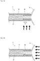
- the resin tip 20 when pushing the coil 11 to take out the resin tip 20 from the sheath 32, the resin tip 20 is preferably in contact with the distal end part of the sheath 32. Since the in-vivo indwelling instrument 10 of the present invention can improve the flexibility of the distal end part as compared to the conventional in-vivo indwelling instruments, the resin tip 20 is in contact with the distal end part of the sheath 32 when taking out the resin tip 20 from the sheath 32 as well. At this time, as illustrated in Fig. 10 , the resin tip 20 may be in contact with an edge 32c at which an inner side face 32a and a distal end face 32b of the sheath 32 intersect with each other. Although not illustrated, the resin tip 20 may be in contact with the distal end face 32b of the sheath 32.
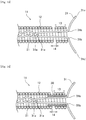
- FIG. 11 and 12 are a side view and Fig.s 13 to 16 are a cross-sectional view (a partial side view) for explaining a method for producing an in-vivo indwelling instrument according to an embodiment of the present invention.
- a method for producing an in-vivo indwelling instrument 10 includes: preparing a coil 11 formed by winding a wire 12, and a wire-shaped member 31 having a folded part 31a to which a stretch resistant member 21 is connected; forming a separating part 14 in the coil 11 by making wider an interval between adjacent wires 12 of the coil 11; inserting the folded part 31a of the wire-shaped member 31 into a lumen of the coil 11; inserting a tubular member 30 into the lumen of the coil 11; heating the tubular member 30, and heating the wire-shaped member 31. Details of each step will be described.
- the abovementioned producing method includes the step of preparing the coil 11 formed by winding the wire 12, and a wire-shaped member 31 that has a folded part 31a to which the stretch resistant member 21 is connected.
- a secondary coil formed by a primary coil which is formed by a metal wire being wound spirally, being further wound spirally or in a three-dimensional shape, can be used.
- the secondary coil can be molded by, for example, winding the primary coil around a mandrel to be subjected to heat treatment, and thereafter, for example, winding the heat-treated primary coil around a mandrel having a different outer shape or being subject to further heat treatment by, for example, inserting a heat-treated coil 11 into a mold.
- Fig. 11 illustrates the wire-shaped member 31 in which the stretch resistant member 21 is connected to the folded part 31a.
- the wire-shaped member 31 is a member which, in a following stage, may be provided as the mooring part 20b of the resin tip 20.
- the folded part 31a is preferably formed at the proximal end part of the wire-shaped member 31. Since one side and the other side of the wire-shaped member 31 having the folded part 31a therebetween can move freely, it is possible to disperse the stress of the resin tip 20. Furthermore, by hooking the stretch resistant member 21 at the folded part 31a of the wire-shaped member 31, it is possible to readily connect the wire-shaped member 31 and the stretch resistant member 21. It is possible to form the folded part 31a by bending the wire-shaped member 31.
- Fig. 11 illustrates an example in which a single folded part 31a is provided, but a plurality of folded parts 31a may be provided.
- the folded part 31a since the folded part 31a is formed at the middle position of the wire-shaped member 31 in the axial direction, the one side and the other side thereof having the folded part 31a have substantially the same length, but the one side and the other side may have the same length or may have different lengths.
- the folded part 31a may be formed by bending the wire-shaped member 31 in a manner that one end 31c (first end) of the wire-shaped member 31 is located closer to the distal side than the other end 31d (second end), and the other end 31d may be fixed in the middle of the wire-shaped member 31 to form a loop on the proximal side of the wire-shaped member 31.
- the stretch resistant member 21 is preferably connected to the loop of the wire-shaped member 31.
- the length of the wire-shaped member 31 is not particularly limited, and may be, for example, 3 mm or more, or 4 mm or more, or alternatively, may be 10 mm or less, or 8 mm or less.
- the outer diameter of the wire-shaped member 31 may be larger or smaller than the outer diameter of the stretch resistant member 21.
- the outer diameter of the wire-shaped member 31 may be, for example, 20 pm or more, 40 pm or more, or 50 pm or more, or alternatively, may be 100 pm or less, or 80 pm or less.
- the length L1 of the wire-shaped member 31 in the axial direction of the coil 11 is not particularly limited, and, for example, may be 5 mm or more, 6 mm or more, or 8 mm or more, or alternatively, may be 15 mm or less, 12 mm or less, or 10 mm or less. With such a configuration, the part of the wire-shaped member 31 that is connected to the stretch resistant member 21 is difficult to be deformed even if the tubular member 30 is heated in a following stage.
- the abovementioned producing method includes the step of forming the separating part 14 in the coil 11 by making wider the interval between adjacent wires 12 of the coil 11.
- a method for forming the separating part 14 in the coil 11 include a method for making wider the interval between adjacent wires 12 of the coil 11 by picking and holding the wire 12 by a pincette, and a method for making wider the interval between adjacent wires 12 of the coil 11 by inserting a member in a flat shape such as a razor thereinto.
- "1. in-vivo indwelling instrument" can be referred to.
- the abovementioned producing method may further include a step for forming a separating part (second separating part) in which the parts of the wire 12 that are adjacent to each other are separated from each other on the distal side of the contacting part 13 of the coil 11.
- the abovementioned producing method includes the step of inserting the folded part 31a of the wire-shaped member 31 into the lumen of the coil 11. Specifically, it is preferable to insert the folded part 31a of the wire-shaped member 31 into the lumen of the coil 11 so that the one end 31c (first end) and the other end 31d (second end) in the axial direction of the wire-shaped member 31 each extend from the distal end of the coil 11. At this time, the proximal end of the wire-shaped member 31 is preferably provided on the proximal side of the separating part 14.
- one or a plurality of bending parts 31b are provided in the wire-shaped member 31 so that the distal end parts of the wire-shaped member 31 extend outwards in the radial direction of the coil 11.
- the plurality of bending parts 31b are preferably provided in a linearly symmetric shape with a central axis of the coil 11 as a symmetric axis.
- the abovementioned producing method includes the step of inserting the tubular member 30 into the lumen of the coil 11. Specifically, it is preferable to insert the tubular member 30 into the lumen of the coil 11 from the distal side of the coil 11.
- the tubular member 30 is a member which, in a following stage, may be provided as a part which is bonded on the inner side face of the coil 11 of at least the resin tip 20.
- materials described as the examples of the materials of the wire-shaped member 31 can also be employed.
- the materials of the tubular member 30 and the wire-shaped member 31 may be the same or different.
- the maximum outer diameter of the tubular member 30 is preferably equal to or smaller than the maximum inner diameter of the coil 11.
- the length of the tubular member 30 in the axial direction of the coil 11 before heating is preferably three times or more the outer diameter of the wire 12 that constitutes the coil 11, more preferably four times or more, or alternatively, ten times or less, or eight times or less the outer diameter of the wire 12 that constitutes the coil 11, as an acceptable length. Since the tubular member 30 is hardened after heating, the length of the tubular member 30 is preferably set as described above in order to secure the flexibility of the in-vivo indwelling instrument 10.
- the proximal end of the tubular member 30 is preferably provided on the proximal side of the proximal end of the separating part 14. With such a configuration, a resin readily flows into the separating part 14. Therefore, it is possible to firmly fix the resin tip 20 with the coil 11.
- the proximal end of the tubular member 30 is preferably provided on the distal side of the proximal end of the wire-shaped member 31.
- the tubular member 30 is heated and melted in a following stage, and joined on the inner side face of the coil 11, a result of which the rigidity of the distal end part of the in-vivo indwelling instrument 10 is locally improved; however, by providing the tubular member 30 and the wire-shaped member 31 in this way, it is possible to secure the flexibility of distal end part of the in-vivo indwelling instrument 10.
- the proximal end of the tubular member 30 may be provided on the proximal side of the proximal end of the wire-shaped member 31. With such a configuration, even though the tubular member 30 is heated in a following stage, it is possible to inhibit the stretch resistant member 21 connected to the wire-shaped member 31 from being deformed due to heating.
- the present embodiment describes the example of performing the step of inserting the tubular member 30 into the lumen of the coil 11 after the step of inserting the folded part 31a of the wire-shaped member 31 into the lumen of the coil 11, but the step of inserting the folded part 31a of the wire-shaped member 31 into the lumen of the coil 11 may be performed after the step of inserting the tubular member 30 into the lumen of the coil 11. Furthermore, the folded part 31a of the wire-shaped member 31 may be inserted into the lumen of the tubular member 30, following which the wire-shaped member 31 and the tubular member 30 may be inserted together into the lumen of the coil 11.
- the abovementioned producing method includes the step of heating the tubular member 30.
- the tubular member 30 may be heated externally in the radial direction of the coil 11.
- the tubular member 30 is preferably heated in a vertical direction with respect to the coil 11.
- the tubular member 30 is melted and flows into the separating part 14 of the coil 11, and is joined on the inner side face of the contacting part 13 of the coil 11.
- the resin tip 20 is firmly fixed with the coil 11.
- Examples of a method for heating the wire-shaped member 31 include a method for causing a heat generation device such as a heater and a soldering iron to be brought closer to the coil 11.
- the tubular member 30 may be heated in a state of making wider the interval between adjacent wires 12 of the coil 11, aside from the separating part 14.
- the tubular member 30 is preferably heated in a state of making wider the interval between adjacent wires 12 of the coil 11 proximal to the separating part 14.
- the tubular member 30 is preferably heated in a state of making wider the interval between adjacent wires 12 of the coil 11 proximal to the proximal end of the tubular member 30.
- the tubular member 30 is preferably heated in a state of making wider the interval between adjacent wires 12 of the coil 11 distal to the proximal end of the wire-shaped member 31.
- the tubular member 30 may be heated in a state of making wider the interval between adjacent wires 12 of the coil 11 proximal to of the middle point located between the distal end of the coil 11 and the proximal end of the wire-shaped member 31.
- the lumen of the coil 11 is likely to be filled with the heat.
- the heat is released by making wider the interval between adjacent wires 12 of the coil 11 proximal to the separating part 14, it is possible to inhibit the wire-shaped member 31 or the stretch resistant member 21 from being heated excessively while the tubular member 30 is locally heated to the extent that the tubular member 30 can be melted.
- Examples of the method for making wider the interval between adjacent wires 12 of the coil 11 include a method for picking and holding the wire 12 by a pincette.
- the abovementioned producing method includes the step of heating the wire-shaped member 31. Specifically, it is preferable to heat the wire-shaped member 31 from the distal side of the coil 11. In other words, it is preferable to heat the wire-shaped member 31 in a horizontal direction with respect to the coil 11. By the wire-shaped member 31 being melted, a tip end part 20a of the resin tip 20 is formed.
- a method for heating the wire-shaped member 31 a method similar to the method for heating the tubular member 30 can be employed.
- the present embodiment describes the example of performing the step of heating the tubular member 30 after the step of heating the wire-shaped member 31.
- the step of heating the wire-shaped member 31 may be performed after the step of heating the tubular member 30.
- tubular member 30 and the wire-shaped member 31 may be heated in the same step of heating. This makes it possible to simplify the producing process of the in-vivo indwelling instrument 10.
- the method for producing the in-vivo indwelling instrument of the present invention described above, since a part of the tubular member 30 that is heated is melted and flows into the separating part 14 of the coil 11, it is possible to manufacture an in-vivo indwelling instrument 10 in which the coil 11 is firmly fixed with the resin tip 20. Furthermore, by providing the separating part 14 in the coil 11, it is possible to inhibit a resin from flowing on a proximal side of the separating part 14 owing to the capillary phenomenon. This makes it possible to secure the flexibility of the distal end part of the in-vivo indwelling instrument 10.
Landscapes
- Health & Medical Sciences (AREA)
- Surgery (AREA)
- Life Sciences & Earth Sciences (AREA)
- Biomedical Technology (AREA)
- Medical Informatics (AREA)
- Vascular Medicine (AREA)
- Reproductive Health (AREA)
- Engineering & Computer Science (AREA)
- Veterinary Medicine (AREA)
- Heart & Thoracic Surgery (AREA)
- Nuclear Medicine, Radiotherapy & Molecular Imaging (AREA)
- Molecular Biology (AREA)
- Animal Behavior & Ethology (AREA)
- General Health & Medical Sciences (AREA)
- Public Health (AREA)
- Neurosurgery (AREA)
- Surgical Instruments (AREA)
- Media Introduction/Drainage Providing Device (AREA)
Applications Claiming Priority (2)
| Application Number | Priority Date | Filing Date | Title |
|---|---|---|---|
| JP2017147760 | 2017-07-31 | ||
| PCT/JP2018/017219 WO2019026364A1 (fr) | 2017-07-31 | 2018-04-27 | Instrument à demeure in vivo, système de pose d'instrument à demeure in vivo et procédé de fabrication d'instrument à demeure in vivo |
Publications (2)
| Publication Number | Publication Date |
|---|---|
| EP3662846A1 true EP3662846A1 (fr) | 2020-06-10 |
| EP3662846A4 EP3662846A4 (fr) | 2021-08-04 |
Family
ID=65233661
Family Applications (1)
| Application Number | Title | Priority Date | Filing Date |
|---|---|---|---|
| EP18841280.3A Pending EP3662846A4 (fr) | 2017-07-31 | 2018-04-27 | Instrument à demeure in vivo, système de pose d'instrument à demeure in vivo et procédé de fabrication d'instrument à demeure in vivo |
Country Status (5)
| Country | Link |
|---|---|
| US (1) | US11504131B2 (fr) |
| EP (1) | EP3662846A4 (fr) |
| JP (1) | JP7063903B2 (fr) |
| CN (1) | CN110636803B (fr) |
| WO (1) | WO2019026364A1 (fr) |
Families Citing this family (4)
| Publication number | Priority date | Publication date | Assignee | Title |
|---|---|---|---|---|
| CN112447392B (zh) * | 2019-08-31 | 2021-11-16 | 深圳硅基仿生科技有限公司 | 具有生物相容性的线圈的绕制方法 |
| EP4064998A1 (fr) * | 2019-11-26 | 2022-10-05 | Koninklijke Philips N.V. | Marqueur radio-opaque durci par rayonnement électromagnétique et dispositifs, systèmes et méthodes associés |
| US20230123450A1 (en) * | 2021-10-05 | 2023-04-20 | Olympus Medical Systems Corp. | Medical apparatus with embedded marking |
| WO2026004363A1 (fr) * | 2024-06-28 | 2026-01-02 | 株式会社カネカ | Outil à demeure in vivo et procédé de production d'outil à demeure in vivo |
Family Cites Families (31)
| Publication number | Priority date | Publication date | Assignee | Title |
|---|---|---|---|---|
| US5766160A (en) * | 1995-06-06 | 1998-06-16 | Target Therapeutics, Inc. | Variable stiffness coils |
| DK177010B1 (da) | 1996-09-03 | 2010-11-29 | Cook William Europ | Embolisationsindretning til placering i et blodkar |
| JP3754145B2 (ja) | 1996-09-20 | 2006-03-08 | 株式会社カネカメディックス | 生体内留置部材を有する医療用ワイヤー |
| US5984929A (en) | 1997-08-29 | 1999-11-16 | Target Therapeutics, Inc. | Fast detaching electronically isolated implant |
| JP4355038B2 (ja) * | 1997-09-01 | 2009-10-28 | 株式会社カネカメディックス | 血管塞栓用具 |
| US6159165A (en) | 1997-12-05 | 2000-12-12 | Micrus Corporation | Three dimensional spherical micro-coils manufactured from radiopaque nickel-titanium microstrand |
| US6168570B1 (en) | 1997-12-05 | 2001-01-02 | Micrus Corporation | Micro-strand cable with enhanced radiopacity |
| US6136015A (en) | 1998-08-25 | 2000-10-24 | Micrus Corporation | Vasoocclusive coil |
| US6241691B1 (en) | 1997-12-05 | 2001-06-05 | Micrus Corporation | Coated superelastic stent |
| US6280457B1 (en) * | 1999-06-04 | 2001-08-28 | Scimed Life Systems, Inc. | Polymer covered vaso-occlusive devices and methods of producing such devices |
| JP3994148B2 (ja) * | 2002-05-29 | 2007-10-17 | 株式会社カネカ | 離脱型塞栓コイル |
| US20040002732A1 (en) * | 2002-06-27 | 2004-01-01 | Clifford Teoh | Stretch-resistant vaso-occlusive assembly with multiple detaching points |
| US7569626B2 (en) * | 2003-06-05 | 2009-08-04 | Dfine, Inc. | Polymer composites for biomedical applications and methods of making |
| US7608089B2 (en) | 2004-12-22 | 2009-10-27 | Boston Scientific Scimed, Inc. | Vaso-occlusive device having pivotable coupling |
| US7766933B2 (en) | 2006-03-31 | 2010-08-03 | Codman & Shurtleff, Inc. | Stretch resistant design for embolic coils with stabilization bead |
| US8034073B2 (en) * | 2006-08-18 | 2011-10-11 | Codman & Shurtleff, Inc. | Stretch resistant embolic coil |
| AU2008359873B8 (en) | 2007-07-27 | 2015-09-10 | Microvention, Inc. | Detachable coil incorporating stretch resistance |
| DE102009009003A1 (de) * | 2009-02-16 | 2010-08-26 | Justus-Liebig-Universität Giessen | Implantat |
| WO2010123003A1 (fr) | 2009-04-20 | 2010-10-28 | 株式会社カネカ | Bobine d'embolisation |
| WO2010134364A1 (fr) | 2009-05-20 | 2010-11-25 | 日本ライフライン株式会社 | Fil guide médical |
| US9474532B2 (en) | 2009-09-09 | 2016-10-25 | Kaneka Corporation | Embolization coil |
| AU2010313530B2 (en) * | 2009-10-26 | 2015-12-17 | Microvention, Inc. | Embolization device constructed from expansile polymer |
| US9220506B2 (en) | 2010-06-16 | 2015-12-29 | DePuy Synthes Products, Inc. | Occlusive device with stretch resistant member and anchor filament |
| US20120253381A1 (en) * | 2011-03-31 | 2012-10-04 | Codman & Shurtleff, Inc. | Occlusive device with porous structure and stretch resistant member |
| US9011480B2 (en) * | 2012-01-20 | 2015-04-21 | Covidien Lp | Aneurysm treatment coils |
| US8920459B2 (en) * | 2012-03-30 | 2014-12-30 | DePuy Synthes Products, LLC | Embolic coil detachment mechanism with flexible distal member and resistive electrical heating element |
| EP2668915A1 (fr) | 2012-06-01 | 2013-12-04 | Acandis GmbH & Co. KG | Système permettant de fournir un dispositif vaso-occlusif résistant à l'étirement et son procédé de production |
| US9566071B2 (en) | 2013-04-11 | 2017-02-14 | Blockade Medical, LLC | Systems and devices for cerebral aneurysm repair |
| EP3035867B1 (fr) | 2013-08-20 | 2017-07-19 | Stryker Corporation | Système de pose de dispositif pour occlusion vasculaire |
| US9566072B2 (en) | 2013-12-27 | 2017-02-14 | Blockade Medical, LLC | Coil system |
| JP6429936B2 (ja) | 2017-05-09 | 2018-11-28 | Kddi株式会社 | 位置情報管理装置、位置情報管理方法、及びプログラム |
-
2018
- 2018-04-27 EP EP18841280.3A patent/EP3662846A4/fr active Pending
- 2018-04-27 US US16/622,192 patent/US11504131B2/en active Active
- 2018-04-27 WO PCT/JP2018/017219 patent/WO2019026364A1/fr not_active Ceased
- 2018-04-27 CN CN201880032366.3A patent/CN110636803B/zh active Active
- 2018-04-27 JP JP2019533901A patent/JP7063903B2/ja active Active
Also Published As
| Publication number | Publication date |
|---|---|
| CN110636803A (zh) | 2019-12-31 |
| US11504131B2 (en) | 2022-11-22 |
| WO2019026364A1 (fr) | 2019-02-07 |
| CN110636803B (zh) | 2022-12-27 |
| EP3662846A4 (fr) | 2021-08-04 |
| US20200107839A1 (en) | 2020-04-09 |
| JP7063903B2 (ja) | 2022-05-09 |
| JPWO2019026364A1 (ja) | 2020-05-28 |
Similar Documents
| Publication | Publication Date | Title |
|---|---|---|
| AU2009303677B2 (en) | Vaso-occlusive coil delivery system | |
| JP4528826B2 (ja) | 動脈瘤の治療用血管閉塞デバイス | |
| CN105530874B (zh) | 血管闭塞线圈输送组件及血管闭塞线圈输送系统 | |
| CN108472042B (zh) | 血管闭塞装置和递送组件 | |
| US11504131B2 (en) | In-vivo indwelling instrument, in-vivo indwelling instrument delivering system and method for producing in-vivo indwelling instrument | |
| JP2012000464A (ja) | 伸長抵抗性部材及びアンカーフィラメントを備えた閉塞デバイス | |
| US20200129185A1 (en) | In-vivo indwelling instrument and in-vivo indwelling instrument delivering system | |
| US20240423628A1 (en) | Medical device | |
| US20250082337A1 (en) | Implant Delivery System | |
| JP6855231B2 (ja) | 移植可能な血管閉塞装置送達システムの非平面加熱チャンバー分離機構 | |
| US20240423633A1 (en) | Medical device |
Legal Events
| Date | Code | Title | Description |
|---|---|---|---|
| STAA | Information on the status of an ep patent application or granted ep patent |
Free format text: STATUS: THE INTERNATIONAL PUBLICATION HAS BEEN MADE |
|
| PUAI | Public reference made under article 153(3) epc to a published international application that has entered the european phase |
Free format text: ORIGINAL CODE: 0009012 |
|
| STAA | Information on the status of an ep patent application or granted ep patent |
Free format text: STATUS: REQUEST FOR EXAMINATION WAS MADE |
|
| 17P | Request for examination filed |
Effective date: 20191209 |
|
| AK | Designated contracting states |
Kind code of ref document: A1 Designated state(s): AL AT BE BG CH CY CZ DE DK EE ES FI FR GB GR HR HU IE IS IT LI LT LU LV MC MK MT NL NO PL PT RO RS SE SI SK SM TR |
|
| AX | Request for extension of the european patent |
Extension state: BA ME |
|
| DAV | Request for validation of the european patent (deleted) | ||
| DAX | Request for extension of the european patent (deleted) | ||
| RIC1 | Information provided on ipc code assigned before grant |
Ipc: A61B 17/12 20060101AFI20210329BHEP |
|
| A4 | Supplementary search report drawn up and despatched |
Effective date: 20210707 |
|
| RIC1 | Information provided on ipc code assigned before grant |
Ipc: A61B 17/12 20060101AFI20210701BHEP |
|
| STAA | Information on the status of an ep patent application or granted ep patent |
Free format text: STATUS: EXAMINATION IS IN PROGRESS |
|
| 17Q | First examination report despatched |
Effective date: 20241112 |