EP3662988A1 - Verfahren zur optimierung der tröpfchenbildungsrate unter verwendung von tropfung/strahlung für nebenstromübergang von vakuumgesteuerter, auf mikrofluidischen strom fokussierender vorrichtung mit rechteckigen mikrokanälen - Google Patents
Verfahren zur optimierung der tröpfchenbildungsrate unter verwendung von tropfung/strahlung für nebenstromübergang von vakuumgesteuerter, auf mikrofluidischen strom fokussierender vorrichtung mit rechteckigen mikrokanälen Download PDFInfo
- Publication number
- EP3662988A1 EP3662988A1 EP19154449.3A EP19154449A EP3662988A1 EP 3662988 A1 EP3662988 A1 EP 3662988A1 EP 19154449 A EP19154449 A EP 19154449A EP 3662988 A1 EP3662988 A1 EP 3662988A1
- Authority
- EP
- European Patent Office
- Prior art keywords
- dispersed phase
- continuous
- channel
- channels
- flow
- Prior art date
- Legal status (The legal status is an assumption and is not a legal conclusion. Google has not performed a legal analysis and makes no representation as to the accuracy of the status listed.)
- Granted
Links
Images


Classifications
-
- B—PERFORMING OPERATIONS; TRANSPORTING
- B01—PHYSICAL OR CHEMICAL PROCESSES OR APPARATUS IN GENERAL
- B01F—MIXING, e.g. DISSOLVING, EMULSIFYING OR DISPERSING
- B01F23/00—Mixing according to the phases to be mixed, e.g. dispersing or emulsifying
- B01F23/40—Mixing liquids with liquids; Emulsifying
- B01F23/41—Emulsifying
- B01F23/4105—Methods of emulsifying
-
- B—PERFORMING OPERATIONS; TRANSPORTING
- B01—PHYSICAL OR CHEMICAL PROCESSES OR APPARATUS IN GENERAL
- B01F—MIXING, e.g. DISSOLVING, EMULSIFYING OR DISPERSING
- B01F23/00—Mixing according to the phases to be mixed, e.g. dispersing or emulsifying
- B01F23/40—Mixing liquids with liquids; Emulsifying
- B01F23/41—Emulsifying
-
- B—PERFORMING OPERATIONS; TRANSPORTING
- B01—PHYSICAL OR CHEMICAL PROCESSES OR APPARATUS IN GENERAL
- B01F—MIXING, e.g. DISSOLVING, EMULSIFYING OR DISPERSING
- B01F33/00—Other mixers; Mixing plants; Combinations of mixers
- B01F33/30—Micromixers
- B01F33/301—Micromixers using specific means for arranging the streams to be mixed, e.g. channel geometries or dispositions
- B01F33/3011—Micromixers using specific means for arranging the streams to be mixed, e.g. channel geometries or dispositions using a sheathing stream of a fluid surrounding a central stream of a different fluid, e.g. for reducing the cross-section of the central stream or to produce droplets from the central stream
-
- B—PERFORMING OPERATIONS; TRANSPORTING
- B01—PHYSICAL OR CHEMICAL PROCESSES OR APPARATUS IN GENERAL
- B01F—MIXING, e.g. DISSOLVING, EMULSIFYING OR DISPERSING
- B01F35/00—Accessories for mixers; Auxiliary operations or auxiliary devices; Parts or details of general application
- B01F35/71—Feed mechanisms
- B01F35/717—Feed mechanisms characterised by the means for feeding the components to the mixer
- B01F35/718—Feed mechanisms characterised by the means for feeding the components to the mixer using vacuum, under pressure in a closed receptacle or circuit system
-
- C—CHEMISTRY; METALLURGY
- C09—DYES; PAINTS; POLISHES; NATURAL RESINS; ADHESIVES; COMPOSITIONS NOT OTHERWISE PROVIDED FOR; APPLICATIONS OF MATERIALS NOT OTHERWISE PROVIDED FOR
- C09K—MATERIALS FOR MISCELLANEOUS APPLICATIONS, NOT PROVIDED FOR ELSEWHERE
- C09K23/00—Use of substances as emulsifying, wetting, dispersing, or foam-producing agents
- C09K23/007—Organic compounds containing halogen
-
- B—PERFORMING OPERATIONS; TRANSPORTING
- B01—PHYSICAL OR CHEMICAL PROCESSES OR APPARATUS IN GENERAL
- B01F—MIXING, e.g. DISSOLVING, EMULSIFYING OR DISPERSING
- B01F2101/00—Mixing characterised by the nature of the mixed materials or by the application field
- B01F2101/23—Mixing of laboratory samples e.g. in preparation of analysing or testing properties of materials
-
- B—PERFORMING OPERATIONS; TRANSPORTING
- B01—PHYSICAL OR CHEMICAL PROCESSES OR APPARATUS IN GENERAL
- B01F—MIXING, e.g. DISSOLVING, EMULSIFYING OR DISPERSING
- B01F23/00—Mixing according to the phases to be mixed, e.g. dispersing or emulsifying
- B01F23/40—Mixing liquids with liquids; Emulsifying
- B01F23/41—Emulsifying
- B01F23/414—Emulsifying characterised by the internal structure of the emulsion
- B01F23/4143—Microemulsions
-
- B—PERFORMING OPERATIONS; TRANSPORTING
- B01—PHYSICAL OR CHEMICAL PROCESSES OR APPARATUS IN GENERAL
- B01F—MIXING, e.g. DISSOLVING, EMULSIFYING OR DISPERSING
- B01F23/00—Mixing according to the phases to be mixed, e.g. dispersing or emulsifying
- B01F23/40—Mixing liquids with liquids; Emulsifying
- B01F23/41—Emulsifying
- B01F23/414—Emulsifying characterised by the internal structure of the emulsion
- B01F23/4145—Emulsions of oils, e.g. fuel, and water
Definitions
- the present invention relates to a method for optimizing the production of droplet formation rates in a microfluidic flow-focusing device with rectangular microchannels by changing the dripping/jetting to co-flow transition points. More specifically, the present invention provides a method for microfluidic users to target more precisely engineered droplet formation rates by varying the channel dimensions of the continuous and dispersed phase at the oil-to-water junction.
- An emulsion refers to a two-phase system where liquid droplets are suspended in another liquid and the two liquids do not dissolve within another.
- Common examples of emulsions include oil droplets dispersed in a water-continuous solution or vice-versa.
- the dispersed phase refers to the liquid phase distributed in the form of droplets in another solution.
- the continuous phase refers to the surrounding fluid in which the droplets are dispersed.
- Microfluidic drop-making technology is used for many biological and chemical assays such as enzymatic kinetic assays, high-throughput screening, hydrogel bead formation and polymer particle synthesis.
- a vacuum system For less experienced microfluidic users, implementing a vacuum system is considered a more convenient experimental setup for producing highly monodispersed droplets compared to other common methods of droplet dispersion such as a syringe pump. Moreover, because a vacuum system can be operated using a manual gas valve, the effects of pressure change in the system is immediate while syringe pumps, operated by an automated software, experience time delays for flow rate changes.
- microfluidic droplet formation includes the following geometries: coaxial, T-junction (sometimes Y-junction), and flow-focusing.
- Coaxial microfluidic devices involve a structure where the inner dispersed phase and the outer continuous phase are hydrodynamically driven in the same direction.
- T-junction microfluidic devices use three channels where the continuous phase channel converges with a cross flowing dispersed phase side channel.
- Flow-focusing microfluidic devices use a structure where two continuous phase side channels converge with a central dispersed phase channel which allows the passing fluids to be hydrodynamically focused into a single collection channel.
- the aqueous solution may consist of more than one component.
- encapsulated reagents inside water solutions include, but are not limited to, polysaccharides, biological cells, beads, hexanes, proteins, enzymes, antibodies, probes labeled with fluorescence, and other biochemical reagents for analysis.
- the aqueous solution may also include a surfactant.
- a surfactant is a substance used to reduce interfacial tension of the suspended liquid droplets and the surrounding fluid, thus reducing coalescence of the dispersed droplets within the solution.
- a non-ionic surfactant or a phosphate-buffered saline (PBS) can sometimes be used as a surfactant as well.
- a surfactant can be added to the aqueous solution in concentrations at about 1%, 3%, 5%, 10%, 15%, 20%, about 25% v/v or in the range of any value in between.
- an oil solution is inserted into the continuous phase channels.
- oil solutions include industrial oil, such as mineral oil, and cooking oil such as grape seed oil, olive oil, soybean oil, and canola oil.
- Oil solutions other than the aforementioned examples are used extensively in fields other than microfluidic research.
- the oil may include at least one organic or organosilicon compound having a backbone structure including atoms selected from carbon, silicon and oxygen.
- the oil solution may include a mixture of various organic compounds, a mixture of organosilicon compounds, or any combination thereof.
- the solution of oil can include any suitable mixture of compounds having different chemical structures and molecular weight.
- Oil solutions may contain any of the following organic compounds or a combination thereof: isocetane, 2-(trifluoromethyl)-3-ethoxydodeca fluorohexane (HFE-7500, 3MTM, NovecTM), heptamethyl nonane (HMN), bis(2-ethylhexyl)carbonate, (tridecafluoro-1,1,2,2-tetrahydrooctyl) tetramethyldisiloxane or silicone oil, etc.
- isocetane 2-(trifluoromethyl)-3-ethoxydodeca fluorohexane (HFE-7500, 3MTM, NovecTM), heptamethyl nonane (HMN), bis(2-ethylhexyl)carbonate, (tridecafluoro-1,1,2,2-tetrahydrooctyl) tetramethyldisiloxane or silicone oil, etc.
- Every microfluidic device has to be fine-tuned to satisfy the requirements of each experiment. Therefore, the chemical and physical characteristics of the continuous and dispersed phase as well as the operating parameters of the microfluidic device such as viscosity ratio, flow rate ratio, interfacial tension, channel geometry, and curvature must be carefully selected and engineered. In other words, to effectively optimize microfluidic droplet formation, the user must understand the different physical forces exerted on the dropmaker device.
- microfluidic users frequently report difficulties arising in accurately managing the flow rates of each phase and finding optimal values of the channel aspect ratio, curvature, interfacial tension and dynamic viscosity of each fluid, thus failing to produce the intended level of droplet formation rates.
- Korean Patent Application No. 10-2015-0051487 reports a method for producing smaller-sized droplets with narrower degrees of distribution and excellent characteristics of monodispersion while controlling the capillary constant and flow rates of both phases.
- An aqueous solution containing polysaccharides consists of carboxylic acid groups was used as the dispersed phase.
- An oil solution consisting of calcium ions was used as the continuous phase. It was noted that the microfluidics users experienced difficulty gaining control of the variables used for the experiments such as the flow rates of each phase.
- Capillary number and Weber number Two dimensionless numbers, Capillary number and Weber number, can be used to characterize the flow of the fluids inside the microfluidic device.
- Capillary number (Ca) expresses the viscosity of a fluid relative to the effects of surface tension
- Weber number (We) represents the inertial force of a fluid relative to the effects of surface tension.
- Capillary number and Weber number change based on the values of the operating parameters such as flow rate, viscosity, interfacial tension, channel dimension, vacuum pressure, etc.
- ⁇ (Mu) is the dynamic viscosity of fluid
- Q is the flow rate
- ⁇ (Gamma) is the interfacial tension
- w is the width of the channel
- h is the height of the channel.
- Weber number measures the balance between inertial forces and the effects of surface tension. When the Weber number is greater than 1, inertial forces dominate over interfacial tension, and when the Weber number is less than 1, interfacial tension outcompetes inertial forces.
- ⁇ (Rho) is the density of the fluid
- v is the velocity
- 1 is the characteristic length (typically, the diameter of the droplet)
- ⁇ (Sigma) is the surface tension.
- the objective of the present invention is to introduce a method for controlling droplet formation rates of a vacuum-driven microfluidic setup in a more accurate, easy-to-use, and accessible way. More specifically, the present invention provides a method for gaining control of the formation rate of highly monodispersed droplets of a vacuum-driven microfluidic device at a certain viscosity ratio, density ratio, interfacial tension, and contact angle between the water/oil solution and surface-treated hydrophobic glass/PDMS.
- the inventor of the present invention specifically investigated the correlation of the dimension of the channels and the formation rate of the droplets.
- the results of the experiment showed that by controlling the height of the continuous and dispersed phase channels, and the width of the central dispersed phase channel, droplets could be controlled and produced at the targeted rate (that is, the rate that maximizes desired output), and the present invention was completed.
- microfluidic users are expected to tailor and fine-tune their devices to target more precisely-engineered droplet rates/sizes and flow rates of the continuous and dispersed phases.
- the present invention introduces a method for optimizing a microfluidic flow-focusing device with rectangular microchannels using a vacuum system by targeting certain droplet formation rates that best suit the needs of an experiment in, comprising:
- the method of the present invention adjusts the heights and widths of the continuous and dispersed phase channels, in particular the heights of the dispersed phase channel and the continuous phase channels at the oil-to-water junction. More specifically, this method pertains to producing droplets in a microfluidic flow-focusing device with rectangular microchannels using a vacuum system, thereby having the effects of producing droplets of a targeted rate (that is, the rate that maximizes desired output) in a more user-friendly, easy-to-use and accessible manner.
- the present invention will enable microfluidic users unfamiliar with the hydrodynamic principles of fluids to effectively produce precisely-controlled droplet rates/sizes and flow rates of the continuous and dispersed phases.
- the optimized method of the present invention is capable of producing droplets of a targeted rate (that is, the rate that maximizes desired output) when using simplified experimental setups such as a vacuum-driven system.
- droplet is defined as a liquid of small volume, typically having a spherical shape, that is surrounded by an immiscible fluid such as the continuous phase of emulsion.
- microdroplet is defined as a droplet with a volume that is equal to or less than 1 microliter, typically between 1 microliter and 1 picoliter. Alternatively, a microdroplet refers to a droplet with a diameter of about 200 micrometer.
- oil refers to any liquid compound that is immiscible with water (or aqueous solution), or a mixture thereof, and typically has a high content of carbon.
- channel is defined as a passage in which fluid flows.
- Channels can be formed by tubes such as a capillary tube and on planar structures such as a chip or a combination thereof.
- a channel may extend along a planar flow route in a straight line, zigzag, or spiral pattern.
- dripping/jetting to co-flow transition is defined as the critical point at which the viscous stresses of the dispersed phase dominate over interfacial tension where droplet dispersions are no longer observed, and the dispersed phase is carried down the junction by the continuous phase in an undisrupted stream.
- target rate or “desired rate” is defined as the intended formation rate of droplets that maximizes output.
- the formation rate of a droplet can be 300, 500, 800, 1500 or 2,000 droplets/sec, depending on the design of the dropmaker.
- the intended formation rates of droplets differ depending on the specific purpose of use and the form. For example, for biochemical assays involving the encapsulation of DNA oligos, the highest possible droplet formation rate may be targeted given a particular dropmaker design.
- the present invention introduces a method for optimizing a microfluidic flow-focusing device with rectangular microchannels using a vacuum system by targeting certain droplet formation rates that best suit the needs of an experiment in, comprising:
- the present invention introduces a method for optimizing a microfluidic flow-focusing device with rectangular microchannels using a vacuum system by targeting certain droplet formation rates that best suit the needs of an experiment in, comprising:
- the heights of the continuous and dispersed phase channels, and the width of the dispersed phase channel may be appropriately adjusted depending on the desired rate of droplet formation.
- the heights and widths of the dispersed phase channel and the continuous phase channel may be independently or identically, but not limited, to 5 ⁇ m to 40 ⁇ m .
- the recorded droplet formation rates of the devices showed that changing the height of the continuous and dispersed phase channels had a greater effect on the droplet formation than changing the width of the channels.
- the channel dimensions at the oil-to-water interface can be modified accordingly to the aforementioned trend.
- higher droplet formation rates can be achieved.
- lower droplet formation rates can be achieved.
- the data is localized to devices with 20 ⁇ m to 25 ⁇ m heights and widths of the continuous and dispersed phase, the same trend in droplet formation rate can be observed in micro fluidic devices with the width of the central dispersed phase channel at the oil-to-water junction ranging from 15 ⁇ m to 30 ⁇ m , and the height of the dispersed phase channel and the continuous phase channels ranging from 15 ⁇ m to 30 ⁇ m .
- the dimension 25 ⁇ m was used as the height of the dispersed phase and the continuous phase channels and 20 ⁇ m was used as the width of the dispersed phase channel.
- the dimension 20 ⁇ m was used as the height of the continuous and dispersed phase channels and 25 ⁇ m was used as the width of the central dispersed phase channel.
- a microfluidic user unfamiliar with the fluid dynamics of the dropmaker design can target certain droplet formation rates by simply determining the optimal height and width of the dispersed and continuous phase channels at the oil-to-water interface.
- the vacuum pressure can be adjusted to better achieve droplet formation at a desired rate.
- the invention is at a dripping regime.
- the invention transitions from a dripping regime to a jetting regime.
- the invention reaches the co-flow regime where both the continuous and dispersed phases are carried down in an undisrupted stream and droplets are no longer produced.
- the vacuum pressure where the co-flow occurs is affected by various operating parameters of the microfluidic device such as the viscosity ratio, flow rate ratio, interfacial tension, etc.
- the aforementioned parameters are often difficult to manipulate when the composition of the solutions used as the continuous and dispersed phase are fixed.
- An easy alternative is to modify the channel dimensions and aspect ratios and produce the optimal droplet formation rate.
- the vacuum pressure at which the co-flow occurs increases.
- the pressure at which co-flow regime occurs can be in the range from -0.19 bar to -0.50 bar.
- the oil solution used for the present invention includes a surfactant.
- the surfactant included in the continuous phase facilitates and stabilizes droplet dispersions by reducing coalescence and promoting channel wetting.
- the types of surfactant used for the present invention are not limited to achieving the purpose of the present invention as shown by examples such as sorbitan monooleate.
- the microfluidic device used for the experiment can be prepared based on polymers, for example, elastomers such as polydimethylsiloxane (PDMS) or polytetrafluoroethylene (PTFE or Teflon®), etc., in mixture with a curing agent.
- elastomers such as polydimethylsiloxane (PDMS) or polytetrafluoroethylene (PTFE or Teflon®), etc.
- a microfluidic channel can be implemented.
- polymers polyethylene terephthalate (PET), polyacrylate, polymethacrylate, polycarbonate, polystyrene, polyethylene, polypropylene, polyvinylchloride, cyclic olefin copolymer (COC), polytetrafluoroethylene, fluorinated polymer, silicone such as polydimethylsiloxane, polyvinylidene chloride, bis-benzocyclobutene (BCB), polyimide, fluorinated derivatives of polyimide, etc.
- PET polyethylene terephthalate
- COC cyclic olefin copolymer
- fluorinated polymer silicone such as polydimethylsiloxane, polyvinylidene chloride, bis-benzocyclobutene (BCB), polyimide, fluorinated derivatives of polyimide, etc.
- the channel of the present invention can be processed with various coating substances.
- coating substances such as siloxane.
- the microfluidic flow-focusing device used was fabricated with PDMS (polydimethylsiloxane) using the standard protocols of rapid prototyping, soft lithography and photolithography.
- PDMS polydimethylsiloxane
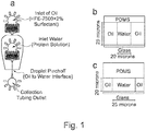
- the microfluidic flow-focusing device manufactured in the present example uses an oil-to-water interface structure that has two continuous phase channels connected perpendicularly to the end of a dispersed phase channel as shown in FIG. 1a .
- the present example in order to verify the effects of the dimensions of the continuous and dispersed phase channels on the formation rate of droplets, based on the connecting region of the dispersed phase channel and the two continuous phase channels, multiple microfluidic flow-focusing devices with different heights of the continuous and dispersed phase channels and width of the central dispersed phase channel were manufactured. More specifically, the height of the channels was changed using different spin speeds and photoresists to adjust the film thickness of an SU-8 film. Moreover, the width of the dispersed phase channel was controlled by modifying the photomask design and using the high-resolution printing.
- the device was manufactured such that the heights of the dispersed phase channel and the continuous phase channels were 20 ⁇ m or 25 ⁇ m , and that the width of the dispersed phase channel was 15 ⁇ m , 20 ⁇ m , 25 ⁇ m or 30 ⁇ m .
- FIG 1b The cross-section of an example microfluidic device with 25 ⁇ m height water and oil channels and 15 ⁇ m width central water channel at the oil-to-water junction is shown in FIG 1b .
- FIG 1c The cross-section of an example microfluidic device with 15 ⁇ m height water and oil channels and 25 ⁇ m width central water channel at the oil-to-water junction is shown in FIG 1c .
- All PDMS microfluidic devices used for the present invention were manufactured such that the widths of the continuous phase channels were 25 ⁇ m , and that the width of the collection channel was 37 ⁇ m .
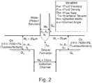
- the top view of the oil-to-water junction where the two side oil channels and the central water channel converge is shown in FIG. 2 .
- aqueous solution consisting of 69.9% of pure water (DI water), 10% of tris-buffer saline solution (Sigma-Aldrich, MO), 20% of glycerol (Sigma-Aldrich, MO) and TBS, and 0.1% of fluorescent additive and bovine serum albumin (Sigma-Aldrich, MO) was used.
- an oil solution consisting of 2-(trifluoromethyl)-3-ethoxydodecafluorohexane (HFE-7500, Novec 7500, 3M, MN) comprising and PEG-based fluorosurfactant (2% by volume) was used.
- FIG. 3 provides a more detailed illustration of present invention's experimental setup.
- a PDMS microfluidic flow-focusing device with 25 ⁇ m height oil and water channels and 15 ⁇ m width central water channel and another a microfluidic device with 25 ⁇ m height water and oil channels and 20 ⁇ m width central water channel were manufactured.
- a vacuum pressure of -0.26 to -0.27 bar was applied to both of the devices.
- the formation rate of the droplet was calculated using image sequences obtained by a high speed camera recorded at a frame speed of 10,000 fps. At least three to five droplets were averaged to find the droplet formation rate at a particular vacuum pressure. The result is shown in FIG. 4 .
- the two devices used in FIG. 4 had the same 25 ⁇ m heights for the continuous and dispersed channels while the width of the central water channels differed by 5 ⁇ m .
- the dropmaker with the narrower width (15 ⁇ m ) produced a formation rate of 833 drop/sec while the dropmaker with wider width (20 ⁇ m ) produced a formation rate of 909.
- the formation rate of the droplets (drops per second) increased only by 9.1%.
- the difference in droplet formation rate relative to the change in the width of the dispersed phase is considered significantly less substantial compared to the difference in droplet rate relative to the change in height of the continuous and dispersed phase channels.
- the aforementioned example elaborated in this example serves as a representative sample of the general trend observed in the larger data set shown in FIG. 6 and 7 .
- a PDMS microfluidic flow-focusing device with 25 ⁇ m heights continuous and dispersed channels and 15 ⁇ m width central dispersed phase channel was prepared to observe the three distinct types of flow regimes.
- An aqueous solution (protein solution) was inserted as the dispersed phase and an oil solution with polyethylene glycol (PEG) based flurosurfactant was used as the continuous phase.
- PEG polyethylene glycol
- a vacuum pressure was applied to hydrodynamically focus both fluids into a collection channel where an emulsion was created. the vacuum pressure was adjusted using a manual gas valve and pressure value was measured using a pressure gauge.
- a dripping regime was observed at a vacuum pressure of -0.06 bar.
- a jetting regime was observed at a vacuum pressure of -0.40 bar.
- a co-flow regime was observed at a vacuum pressure of -0.60 bar.
- a PDMS microfluidic flow-focusing device in which the heights of the continuous and dispersed phase channels were 20 ⁇ m or 25 ⁇ m and the width of the central dispersed phase channel was 15 ⁇ m , 20 ⁇ m , 25 ⁇ m , or 30 ⁇ m was manufactured to observe the difference in formation rates relative to changes in channel height.
- An aqueous solution (protein solution) was inserted as the dispersed phase and an oil solution with polyethylene glycol (PEG) based flurosurfactant was used as the continuous phase.
- PEG polyethylene glycol
- the maximum droplet formation rate was about 380 droplets/sec.
- the maximum droplet formation rate was about 570 droplets/sec.
- the maximum droplet formation rate was about 220 droplets/sec.
- the maximum droplet formation rate was about 570 droplets/sec. All of the aforementioned maximum formation rates are shown in FIG. 6 .
- the maximum droplet formation rate was about 2500 droplets/sec.
- the maximum droplet formation rate was about 2250 droplets/sec.
- the maximum droplet formation rate was about 2600 droplets/sec.
- the maximum droplet formation rate was about 1250 droplets/sec. All of the aforementioned maximum formation rates are shown in FIG. 7 .
- FIG. 6 and 7 show that height of the channel is a much more significant factor in determining droplet formation rate than the width of the channel. More specifically, when the height was increased by 25.0% (increase from 20 ⁇ m to 25 m ), the maximum droplet formation rate increased by approximately 4.3 times.
- PDMS microfluidic flow-focusing devices with the same cross-sectional areas at the oil-to-water interface were each manufactured. More specifically, a microfluidic device with 25 ⁇ m height continuous and dispersed phase channels and 20 ⁇ m width central water channel, and another microfluidic device with 20 ⁇ m height continuous and dispersed phase channels and 25 ⁇ m width central dispersed phase channel were constructed. An aqueous solution (protein solution) was inserted as the dispersed phase and an oil solution with polyethylene glycol (PEG) based flurosurfactant was used as the dispersed phase. Droplet production was performed by applying a vacuum pressure and hydrodynamically focusing both fluids into the collection channel.
- PEG polyethylene glycol
- the microfluidic device with 25 ⁇ m height continuous and dispersed phase channels and 20 ⁇ m width central dispersed phase channel experienced a co-flow regime when the vacuum pressure reached -0.5 bar.
- the microfluidic device with 20 ⁇ m height continuous and dispersed phase channels and 25 ⁇ m width central dispersed phase channel experienced a co-flow regime when the vacuum pressure reached -0.19 bar.
- the dripping/jetting to co-flow transition was determined by averaging at least three to five dropmakers for both devices. Therefore, considering the two devices with the same cross-sectional area but with opposing dimensions, the dropmaker design with higher heights displayed a substantially higher droplet formation rate than the dropmaker design with the same cross-sectional area but with lower heights.
- certain droplet formation rates can be targeted by simply changing the dimensions of the continuous and dispersed phase channels at the oil-to-water interface.
- the height of the continuous and dispersed phase channels can be increased to an appropriate degree.
- height of the continuous and dispersed phase channels can be lowered to an appropriate degree.
Landscapes
- Chemical & Material Sciences (AREA)
- Chemical Kinetics & Catalysis (AREA)
- Engineering & Computer Science (AREA)
- Materials Engineering (AREA)
- Organic Chemistry (AREA)
- Colloid Chemistry (AREA)
- Micromachines (AREA)
- Physical Or Chemical Processes And Apparatus (AREA)
Applications Claiming Priority (1)
| Application Number | Priority Date | Filing Date | Title |
|---|---|---|---|
| US16/207,471 US20200171445A1 (en) | 2018-12-03 | 2018-12-03 | Method for optimization of droplet formation rate using dripping/jetting to co-flow transition of vacuum-driven microfluidic flow-focusing device with rectangular microchannels |
Publications (2)
| Publication Number | Publication Date |
|---|---|
| EP3662988A1 true EP3662988A1 (de) | 2020-06-10 |
| EP3662988B1 EP3662988B1 (de) | 2021-10-06 |
Family
ID=65268780
Family Applications (1)
| Application Number | Title | Priority Date | Filing Date |
|---|---|---|---|
| EP19154449.3A Not-in-force EP3662988B1 (de) | 2018-12-03 | 2019-01-30 | Verfahren zur optimierung der tröpfchenbildungsrate unter verwendung von tropfung/strahlung für nebenstromübergang von vakuumgesteuerter, auf mikrofluidischen strom fokussierender vorrichtung mit rechteckigen mikrokanälen |
Country Status (3)
| Country | Link |
|---|---|
| US (1) | US20200171445A1 (de) |
| EP (1) | EP3662988B1 (de) |
| JP (1) | JP2020089870A (de) |
Families Citing this family (2)
| Publication number | Priority date | Publication date | Assignee | Title |
|---|---|---|---|---|
| CN118320874B (zh) * | 2024-04-08 | 2026-06-23 | 西安交通大学 | 一种基于纳米颗粒表面活性剂调控微通道中液滴运移速度的方法 |
| WO2025222011A1 (en) * | 2024-04-17 | 2025-10-23 | The Trustees Of The University Of Pennsylvania | Convolutional neural network soft-sensor controller for microfluidics |
Citations (4)
| Publication number | Priority date | Publication date | Assignee | Title |
|---|---|---|---|---|
| WO2011028764A2 (en) * | 2009-09-02 | 2011-03-10 | President And Fellows Of Harvard College | Multiple emulsions created using jetting and other techniques |
| KR20150051487A (ko) | 2013-11-04 | 2015-05-13 | 삼성전자주식회사 | 충전 회로를 갖는 휴대형 전자장치 |
| WO2015088299A1 (en) * | 2013-12-09 | 2015-06-18 | Vilnius University | Method for production of biopolymer-based droplets and particles in a microfluidic system |
| WO2016126865A1 (en) * | 2015-02-04 | 2016-08-11 | The Regents Of The University Of California | Multiple-emulsion nucleic acid amplification |
-
2018
- 2018-12-03 US US16/207,471 patent/US20200171445A1/en not_active Abandoned
-
2019
- 2019-01-30 JP JP2019014362A patent/JP2020089870A/ja active Pending
- 2019-01-30 EP EP19154449.3A patent/EP3662988B1/de not_active Not-in-force
Patent Citations (4)
| Publication number | Priority date | Publication date | Assignee | Title |
|---|---|---|---|---|
| WO2011028764A2 (en) * | 2009-09-02 | 2011-03-10 | President And Fellows Of Harvard College | Multiple emulsions created using jetting and other techniques |
| KR20150051487A (ko) | 2013-11-04 | 2015-05-13 | 삼성전자주식회사 | 충전 회로를 갖는 휴대형 전자장치 |
| WO2015088299A1 (en) * | 2013-12-09 | 2015-06-18 | Vilnius University | Method for production of biopolymer-based droplets and particles in a microfluidic system |
| WO2016126865A1 (en) * | 2015-02-04 | 2016-08-11 | The Regents Of The University Of California | Multiple-emulsion nucleic acid amplification |
Also Published As
| Publication number | Publication date |
|---|---|
| US20200171445A1 (en) | 2020-06-04 |
| JP2020089870A (ja) | 2020-06-11 |
| EP3662988B1 (de) | 2021-10-06 |
Similar Documents
| Publication | Publication Date | Title |
|---|---|---|
| US12331287B1 (en) | Assays and other reactions involving droplets | |
| Vladisavljević et al. | Production of uniform droplets using membrane, microchannel and microfluidic emulsification devices | |
| EP2004316B1 (de) | Koaleszenz fluider tröpfchen | |
| CN102059162A (zh) | 微流体器件 | |
| US20160264924A1 (en) | Methods And Apparatuses For Droplet Mixing | |
| US20210370303A1 (en) | Pressure insensitive microfluidic circuit for droplet generation and uses thereof | |
| JP5869482B2 (ja) | ジェッティングおよび他の技術を使用して生成された多重エマルジョン | |
| JP2015513451A (ja) | 流体分割を用いる液滴形成 | |
| Li et al. | A minimalist approach for generating picoliter to nanoliter droplets based on an asymmetrical beveled capillary and its application in digital PCR assay | |
| US11141730B2 (en) | Coalescence of droplets | |
| JP2020169911A (ja) | 液滴アレイ測定に関する装置及び方法 | |
| EP3662988B1 (de) | Verfahren zur optimierung der tröpfchenbildungsrate unter verwendung von tropfung/strahlung für nebenstromübergang von vakuumgesteuerter, auf mikrofluidischen strom fokussierender vorrichtung mit rechteckigen mikrokanälen | |
| Da Ling et al. | Generation of monodisperse micro-droplets within the stable narrowing jetting regime: Effects of viscosity and interfacial tension | |
| Zheng et al. | Microfluidic step emulsification with parallel nozzles on a vertical slit | |
| Moritani et al. | Generation of uniform-size droplets by multistep hydrodynamic droplet division in microfluidic circuits | |
| Castro-Hernández et al. | Study of the geometry in a 3D flow-focusing device | |
| Bezrukov et al. | Control of the phase formation process in solutions of anionic polyelectrolyte—cationic surfactant complexes in a microfluidic channel | |
| Ahn et al. | Production of uniform microspheres using a simple microfluidic device with silica capillary | |
| Opalski | Passive microfluidic systems for development of analytical assays | |
| Mastiani et al. | Understanding Fundamental Physics of Aqueous Droplet Generation Mechanisms in the Aqueous Environment | |
| Christopher | Manipulation of droplets in microfluidic channels using T-junction geometry | |
| JP2021065880A (ja) | 粒子分離装置及び分離方法 |
Legal Events
| Date | Code | Title | Description |
|---|---|---|---|
| PUAI | Public reference made under article 153(3) epc to a published international application that has entered the european phase |
Free format text: ORIGINAL CODE: 0009012 |
|
| STAA | Information on the status of an ep patent application or granted ep patent |
Free format text: STATUS: THE APPLICATION HAS BEEN PUBLISHED |
|
| AK | Designated contracting states |
Kind code of ref document: A1 Designated state(s): AL AT BE BG CH CY CZ DE DK EE ES FI FR GB GR HR HU IE IS IT LI LT LU LV MC MK MT NL NO PL PT RO RS SE SI SK SM TR |
|
| AX | Request for extension of the european patent |
Extension state: BA ME |
|
| STAA | Information on the status of an ep patent application or granted ep patent |
Free format text: STATUS: REQUEST FOR EXAMINATION WAS MADE |
|
| 17P | Request for examination filed |
Effective date: 20201120 |
|
| RBV | Designated contracting states (corrected) |
Designated state(s): AL AT BE BG CH CY CZ DE DK EE ES FI FR GB GR HR HU IE IS IT LI LT LU LV MC MK MT NL NO PL PT RO RS SE SI SK SM TR |
|
| GRAP | Despatch of communication of intention to grant a patent |
Free format text: ORIGINAL CODE: EPIDOSNIGR1 |
|
| STAA | Information on the status of an ep patent application or granted ep patent |
Free format text: STATUS: GRANT OF PATENT IS INTENDED |
|
| INTG | Intention to grant announced |
Effective date: 20210419 |
|
| GRAS | Grant fee paid |
Free format text: ORIGINAL CODE: EPIDOSNIGR3 |
|
| GRAA | (expected) grant |
Free format text: ORIGINAL CODE: 0009210 |
|
| STAA | Information on the status of an ep patent application or granted ep patent |
Free format text: STATUS: THE PATENT HAS BEEN GRANTED |
|
| AK | Designated contracting states |
Kind code of ref document: B1 Designated state(s): AL AT BE BG CH CY CZ DE DK EE ES FI FR GB GR HR HU IE IS IT LI LT LU LV MC MK MT NL NO PL PT RO RS SE SI SK SM TR |
|
| REG | Reference to a national code |
Ref country code: GB Ref legal event code: FG4D |
|
| REG | Reference to a national code |
Ref country code: CH Ref legal event code: EP Ref country code: AT Ref legal event code: REF Ref document number: 1435745 Country of ref document: AT Kind code of ref document: T Effective date: 20211015 |
|
| REG | Reference to a national code |
Ref country code: IE Ref legal event code: FG4D |
|
| REG | Reference to a national code |
Ref country code: DE Ref legal event code: R096 Ref document number: 602019008066 Country of ref document: DE |
|
| REG | Reference to a national code |
Ref country code: DE Ref legal event code: R079 Ref document number: 602019008066 Country of ref document: DE Free format text: PREVIOUS MAIN CLASS: B01F0003080000 Ipc: B01F0023400000 |
|
| REG | Reference to a national code |
Ref country code: LT Ref legal event code: MG9D |
|
| REG | Reference to a national code |
Ref country code: NL Ref legal event code: MP Effective date: 20211006 |
|
| REG | Reference to a national code |
Ref country code: AT Ref legal event code: MK05 Ref document number: 1435745 Country of ref document: AT Kind code of ref document: T Effective date: 20211006 |
|
| PG25 | Lapsed in a contracting state [announced via postgrant information from national office to epo] |
Ref country code: RS Free format text: LAPSE BECAUSE OF FAILURE TO SUBMIT A TRANSLATION OF THE DESCRIPTION OR TO PAY THE FEE WITHIN THE PRESCRIBED TIME-LIMIT Effective date: 20211006 Ref country code: LT Free format text: LAPSE BECAUSE OF FAILURE TO SUBMIT A TRANSLATION OF THE DESCRIPTION OR TO PAY THE FEE WITHIN THE PRESCRIBED TIME-LIMIT Effective date: 20211006 Ref country code: FI Free format text: LAPSE BECAUSE OF FAILURE TO SUBMIT A TRANSLATION OF THE DESCRIPTION OR TO PAY THE FEE WITHIN THE PRESCRIBED TIME-LIMIT Effective date: 20211006 Ref country code: BG Free format text: LAPSE BECAUSE OF FAILURE TO SUBMIT A TRANSLATION OF THE DESCRIPTION OR TO PAY THE FEE WITHIN THE PRESCRIBED TIME-LIMIT Effective date: 20220106 Ref country code: AT Free format text: LAPSE BECAUSE OF FAILURE TO SUBMIT A TRANSLATION OF THE DESCRIPTION OR TO PAY THE FEE WITHIN THE PRESCRIBED TIME-LIMIT Effective date: 20211006 |
|
| PG25 | Lapsed in a contracting state [announced via postgrant information from national office to epo] |
Ref country code: IS Free format text: LAPSE BECAUSE OF FAILURE TO SUBMIT A TRANSLATION OF THE DESCRIPTION OR TO PAY THE FEE WITHIN THE PRESCRIBED TIME-LIMIT Effective date: 20220206 Ref country code: SE Free format text: LAPSE BECAUSE OF FAILURE TO SUBMIT A TRANSLATION OF THE DESCRIPTION OR TO PAY THE FEE WITHIN THE PRESCRIBED TIME-LIMIT Effective date: 20211006 Ref country code: PT Free format text: LAPSE BECAUSE OF FAILURE TO SUBMIT A TRANSLATION OF THE DESCRIPTION OR TO PAY THE FEE WITHIN THE PRESCRIBED TIME-LIMIT Effective date: 20220207 Ref country code: PL Free format text: LAPSE BECAUSE OF FAILURE TO SUBMIT A TRANSLATION OF THE DESCRIPTION OR TO PAY THE FEE WITHIN THE PRESCRIBED TIME-LIMIT Effective date: 20211006 Ref country code: NO Free format text: LAPSE BECAUSE OF FAILURE TO SUBMIT A TRANSLATION OF THE DESCRIPTION OR TO PAY THE FEE WITHIN THE PRESCRIBED TIME-LIMIT Effective date: 20220106 Ref country code: NL Free format text: LAPSE BECAUSE OF FAILURE TO SUBMIT A TRANSLATION OF THE DESCRIPTION OR TO PAY THE FEE WITHIN THE PRESCRIBED TIME-LIMIT Effective date: 20211006 Ref country code: LV Free format text: LAPSE BECAUSE OF FAILURE TO SUBMIT A TRANSLATION OF THE DESCRIPTION OR TO PAY THE FEE WITHIN THE PRESCRIBED TIME-LIMIT Effective date: 20211006 Ref country code: HR Free format text: LAPSE BECAUSE OF FAILURE TO SUBMIT A TRANSLATION OF THE DESCRIPTION OR TO PAY THE FEE WITHIN THE PRESCRIBED TIME-LIMIT Effective date: 20211006 Ref country code: GR Free format text: LAPSE BECAUSE OF FAILURE TO SUBMIT A TRANSLATION OF THE DESCRIPTION OR TO PAY THE FEE WITHIN THE PRESCRIBED TIME-LIMIT Effective date: 20220107 Ref country code: ES Free format text: LAPSE BECAUSE OF FAILURE TO SUBMIT A TRANSLATION OF THE DESCRIPTION OR TO PAY THE FEE WITHIN THE PRESCRIBED TIME-LIMIT Effective date: 20211006 |
|
| REG | Reference to a national code |
Ref country code: DE Ref legal event code: R097 Ref document number: 602019008066 Country of ref document: DE |
|
| PG25 | Lapsed in a contracting state [announced via postgrant information from national office to epo] |
Ref country code: SM Free format text: LAPSE BECAUSE OF FAILURE TO SUBMIT A TRANSLATION OF THE DESCRIPTION OR TO PAY THE FEE WITHIN THE PRESCRIBED TIME-LIMIT Effective date: 20211006 Ref country code: SK Free format text: LAPSE BECAUSE OF FAILURE TO SUBMIT A TRANSLATION OF THE DESCRIPTION OR TO PAY THE FEE WITHIN THE PRESCRIBED TIME-LIMIT Effective date: 20211006 Ref country code: RO Free format text: LAPSE BECAUSE OF FAILURE TO SUBMIT A TRANSLATION OF THE DESCRIPTION OR TO PAY THE FEE WITHIN THE PRESCRIBED TIME-LIMIT Effective date: 20211006 Ref country code: EE Free format text: LAPSE BECAUSE OF FAILURE TO SUBMIT A TRANSLATION OF THE DESCRIPTION OR TO PAY THE FEE WITHIN THE PRESCRIBED TIME-LIMIT Effective date: 20211006 Ref country code: DK Free format text: LAPSE BECAUSE OF FAILURE TO SUBMIT A TRANSLATION OF THE DESCRIPTION OR TO PAY THE FEE WITHIN THE PRESCRIBED TIME-LIMIT Effective date: 20211006 Ref country code: CZ Free format text: LAPSE BECAUSE OF FAILURE TO SUBMIT A TRANSLATION OF THE DESCRIPTION OR TO PAY THE FEE WITHIN THE PRESCRIBED TIME-LIMIT Effective date: 20211006 |
|
| REG | Reference to a national code |
Ref country code: DE Ref legal event code: R119 Ref document number: 602019008066 Country of ref document: DE |
|
| PLBE | No opposition filed within time limit |
Free format text: ORIGINAL CODE: 0009261 |
|
| STAA | Information on the status of an ep patent application or granted ep patent |
Free format text: STATUS: NO OPPOSITION FILED WITHIN TIME LIMIT |
|
| PG25 | Lapsed in a contracting state [announced via postgrant information from national office to epo] |
Ref country code: MC Free format text: LAPSE BECAUSE OF FAILURE TO SUBMIT A TRANSLATION OF THE DESCRIPTION OR TO PAY THE FEE WITHIN THE PRESCRIBED TIME-LIMIT Effective date: 20211006 |
|
| REG | Reference to a national code |
Ref country code: CH Ref legal event code: PL |
|
| 26N | No opposition filed |
Effective date: 20220707 |
|
| REG | Reference to a national code |
Ref country code: BE Ref legal event code: MM Effective date: 20220131 |
|
| PG25 | Lapsed in a contracting state [announced via postgrant information from national office to epo] |
Ref country code: LU Free format text: LAPSE BECAUSE OF NON-PAYMENT OF DUE FEES Effective date: 20220130 Ref country code: DE Free format text: LAPSE BECAUSE OF NON-PAYMENT OF DUE FEES Effective date: 20220802 Ref country code: AL Free format text: LAPSE BECAUSE OF FAILURE TO SUBMIT A TRANSLATION OF THE DESCRIPTION OR TO PAY THE FEE WITHIN THE PRESCRIBED TIME-LIMIT Effective date: 20211006 |
|
| PG25 | Lapsed in a contracting state [announced via postgrant information from national office to epo] |
Ref country code: SI Free format text: LAPSE BECAUSE OF FAILURE TO SUBMIT A TRANSLATION OF THE DESCRIPTION OR TO PAY THE FEE WITHIN THE PRESCRIBED TIME-LIMIT Effective date: 20211006 Ref country code: FR Free format text: LAPSE BECAUSE OF NON-PAYMENT OF DUE FEES Effective date: 20220131 Ref country code: BE Free format text: LAPSE BECAUSE OF NON-PAYMENT OF DUE FEES Effective date: 20220131 |
|
| PG25 | Lapsed in a contracting state [announced via postgrant information from national office to epo] |
Ref country code: LI Free format text: LAPSE BECAUSE OF NON-PAYMENT OF DUE FEES Effective date: 20220131 Ref country code: CH Free format text: LAPSE BECAUSE OF NON-PAYMENT OF DUE FEES Effective date: 20220131 |
|
| PG25 | Lapsed in a contracting state [announced via postgrant information from national office to epo] |
Ref country code: IE Free format text: LAPSE BECAUSE OF NON-PAYMENT OF DUE FEES Effective date: 20220130 |
|
| PG25 | Lapsed in a contracting state [announced via postgrant information from national office to epo] |
Ref country code: IT Free format text: LAPSE BECAUSE OF FAILURE TO SUBMIT A TRANSLATION OF THE DESCRIPTION OR TO PAY THE FEE WITHIN THE PRESCRIBED TIME-LIMIT Effective date: 20211006 |
|
| GBPC | Gb: european patent ceased through non-payment of renewal fee |
Effective date: 20230130 |
|
| PG25 | Lapsed in a contracting state [announced via postgrant information from national office to epo] |
Ref country code: GB Free format text: LAPSE BECAUSE OF NON-PAYMENT OF DUE FEES Effective date: 20230130 |
|
| PG25 | Lapsed in a contracting state [announced via postgrant information from national office to epo] |
Ref country code: MK Free format text: LAPSE BECAUSE OF FAILURE TO SUBMIT A TRANSLATION OF THE DESCRIPTION OR TO PAY THE FEE WITHIN THE PRESCRIBED TIME-LIMIT Effective date: 20211006 Ref country code: CY Free format text: LAPSE BECAUSE OF FAILURE TO SUBMIT A TRANSLATION OF THE DESCRIPTION OR TO PAY THE FEE WITHIN THE PRESCRIBED TIME-LIMIT Effective date: 20211006 |
|
| PG25 | Lapsed in a contracting state [announced via postgrant information from national office to epo] |
Ref country code: HU Free format text: LAPSE BECAUSE OF FAILURE TO SUBMIT A TRANSLATION OF THE DESCRIPTION OR TO PAY THE FEE WITHIN THE PRESCRIBED TIME-LIMIT; INVALID AB INITIO Effective date: 20190130 |
|
| PG25 | Lapsed in a contracting state [announced via postgrant information from national office to epo] |
Ref country code: MT Free format text: LAPSE BECAUSE OF FAILURE TO SUBMIT A TRANSLATION OF THE DESCRIPTION OR TO PAY THE FEE WITHIN THE PRESCRIBED TIME-LIMIT Effective date: 20211006 |
|
| PG25 | Lapsed in a contracting state [announced via postgrant information from national office to epo] |
Ref country code: TR Free format text: LAPSE BECAUSE OF FAILURE TO SUBMIT A TRANSLATION OF THE DESCRIPTION OR TO PAY THE FEE WITHIN THE PRESCRIBED TIME-LIMIT Effective date: 20211006 |