EP3662993A1 - Échantillonnage automatisé d'une installation d'essai de catalyseur parallélisée - Google Patents
Échantillonnage automatisé d'une installation d'essai de catalyseur parallélisée Download PDFInfo
- Publication number
- EP3662993A1 EP3662993A1 EP18210061.0A EP18210061A EP3662993A1 EP 3662993 A1 EP3662993 A1 EP 3662993A1 EP 18210061 A EP18210061 A EP 18210061A EP 3662993 A1 EP3662993 A1 EP 3662993A1
- Authority
- EP
- European Patent Office
- Prior art keywords
- cannula
- outlet
- reactor
- sampling
- vial
- Prior art date
- Legal status (The legal status is an assumption and is not a legal conclusion. Google has not performed a legal analysis and makes no representation as to the accuracy of the status listed.)
- Withdrawn
Links
Images


Classifications
-
- B—PERFORMING OPERATIONS; TRANSPORTING
- B01—PHYSICAL OR CHEMICAL PROCESSES OR APPARATUS IN GENERAL
- B01J—CHEMICAL OR PHYSICAL PROCESSES, e.g. CATALYSIS OR COLLOID CHEMISTRY; THEIR RELEVANT APPARATUS
- B01J19/00—Chemical, physical or physico-chemical processes in general; Their relevant apparatus
- B01J19/0046—Sequential or parallel reactions, e.g. for the synthesis of polypeptides or polynucleotides; Apparatus and devices for combinatorial chemistry or for making molecular arrays
-
- B—PERFORMING OPERATIONS; TRANSPORTING
- B01—PHYSICAL OR CHEMICAL PROCESSES OR APPARATUS IN GENERAL
- B01J—CHEMICAL OR PHYSICAL PROCESSES, e.g. CATALYSIS OR COLLOID CHEMISTRY; THEIR RELEVANT APPARATUS
- B01J2219/00—Chemical, physical or physico-chemical processes in general; Their relevant apparatus
- B01J2219/00274—Sequential or parallel reactions; Apparatus and devices for combinatorial chemistry or for making arrays; Chemical library technology
- B01J2219/00277—Apparatus
- B01J2219/00279—Features relating to reactor vessels
- B01J2219/00281—Individual reactor vessels
- B01J2219/00286—Reactor vessels with top and bottom openings
-
- B—PERFORMING OPERATIONS; TRANSPORTING
- B01—PHYSICAL OR CHEMICAL PROCESSES OR APPARATUS IN GENERAL
- B01J—CHEMICAL OR PHYSICAL PROCESSES, e.g. CATALYSIS OR COLLOID CHEMISTRY; THEIR RELEVANT APPARATUS
- B01J2219/00—Chemical, physical or physico-chemical processes in general; Their relevant apparatus
- B01J2219/00274—Sequential or parallel reactions; Apparatus and devices for combinatorial chemistry or for making arrays; Chemical library technology
- B01J2219/00277—Apparatus
- B01J2219/00279—Features relating to reactor vessels
- B01J2219/00306—Reactor vessels in a multiple arrangement
- B01J2219/00308—Reactor vessels in a multiple arrangement interchangeably mounted in racks or blocks
-
- B—PERFORMING OPERATIONS; TRANSPORTING
- B01—PHYSICAL OR CHEMICAL PROCESSES OR APPARATUS IN GENERAL
- B01J—CHEMICAL OR PHYSICAL PROCESSES, e.g. CATALYSIS OR COLLOID CHEMISTRY; THEIR RELEVANT APPARATUS
- B01J2219/00—Chemical, physical or physico-chemical processes in general; Their relevant apparatus
- B01J2219/00274—Sequential or parallel reactions; Apparatus and devices for combinatorial chemistry or for making arrays; Chemical library technology
- B01J2219/00277—Apparatus
- B01J2219/00279—Features relating to reactor vessels
- B01J2219/00331—Details of the reactor vessels
- B01J2219/00333—Closures attached to the reactor vessels
- B01J2219/00335—Septa
-
- B—PERFORMING OPERATIONS; TRANSPORTING
- B01—PHYSICAL OR CHEMICAL PROCESSES OR APPARATUS IN GENERAL
- B01J—CHEMICAL OR PHYSICAL PROCESSES, e.g. CATALYSIS OR COLLOID CHEMISTRY; THEIR RELEVANT APPARATUS
- B01J2219/00—Chemical, physical or physico-chemical processes in general; Their relevant apparatus
- B01J2219/00274—Sequential or parallel reactions; Apparatus and devices for combinatorial chemistry or for making arrays; Chemical library technology
- B01J2219/00277—Apparatus
- B01J2219/00351—Means for dispensing and evacuation of reagents
- B01J2219/00373—Hollow needles
- B01J2219/00376—Hollow needles in multiple or parallel arrangements
-
- B—PERFORMING OPERATIONS; TRANSPORTING
- B01—PHYSICAL OR CHEMICAL PROCESSES OR APPARATUS IN GENERAL
- B01J—CHEMICAL OR PHYSICAL PROCESSES, e.g. CATALYSIS OR COLLOID CHEMISTRY; THEIR RELEVANT APPARATUS
- B01J2219/00—Chemical, physical or physico-chemical processes in general; Their relevant apparatus
- B01J2219/00274—Sequential or parallel reactions; Apparatus and devices for combinatorial chemistry or for making arrays; Chemical library technology
- B01J2219/00277—Apparatus
- B01J2219/00351—Means for dispensing and evacuation of reagents
- B01J2219/00418—Means for dispensing and evacuation of reagents using pressure
-
- B—PERFORMING OPERATIONS; TRANSPORTING
- B01—PHYSICAL OR CHEMICAL PROCESSES OR APPARATUS IN GENERAL
- B01J—CHEMICAL OR PHYSICAL PROCESSES, e.g. CATALYSIS OR COLLOID CHEMISTRY; THEIR RELEVANT APPARATUS
- B01J2219/00—Chemical, physical or physico-chemical processes in general; Their relevant apparatus
- B01J2219/00274—Sequential or parallel reactions; Apparatus and devices for combinatorial chemistry or for making arrays; Chemical library technology
- B01J2219/00277—Apparatus
- B01J2219/00495—Means for heating or cooling the reaction vessels
-
- B—PERFORMING OPERATIONS; TRANSPORTING
- B01—PHYSICAL OR CHEMICAL PROCESSES OR APPARATUS IN GENERAL
- B01J—CHEMICAL OR PHYSICAL PROCESSES, e.g. CATALYSIS OR COLLOID CHEMISTRY; THEIR RELEVANT APPARATUS
- B01J2219/00—Chemical, physical or physico-chemical processes in general; Their relevant apparatus
- B01J2219/00274—Sequential or parallel reactions; Apparatus and devices for combinatorial chemistry or for making arrays; Chemical library technology
- B01J2219/00583—Features relative to the processes being carried out
- B01J2219/00585—Parallel processes
-
- B—PERFORMING OPERATIONS; TRANSPORTING
- B01—PHYSICAL OR CHEMICAL PROCESSES OR APPARATUS IN GENERAL
- B01J—CHEMICAL OR PHYSICAL PROCESSES, e.g. CATALYSIS OR COLLOID CHEMISTRY; THEIR RELEVANT APPARATUS
- B01J2219/00—Chemical, physical or physico-chemical processes in general; Their relevant apparatus
- B01J2219/00274—Sequential or parallel reactions; Apparatus and devices for combinatorial chemistry or for making arrays; Chemical library technology
- B01J2219/0068—Means for controlling the apparatus of the process
- B01J2219/00702—Processes involving means for analysing and characterising the products
-
- B—PERFORMING OPERATIONS; TRANSPORTING
- B01—PHYSICAL OR CHEMICAL PROCESSES OR APPARATUS IN GENERAL
- B01J—CHEMICAL OR PHYSICAL PROCESSES, e.g. CATALYSIS OR COLLOID CHEMISTRY; THEIR RELEVANT APPARATUS
- B01J2219/00—Chemical, physical or physico-chemical processes in general; Their relevant apparatus
- B01J2219/00274—Sequential or parallel reactions; Apparatus and devices for combinatorial chemistry or for making arrays; Chemical library technology
- B01J2219/00718—Type of compounds synthesised
- B01J2219/00745—Inorganic compounds
- B01J2219/00747—Catalysts
-
- G—PHYSICS
- G01—MEASURING; TESTING
- G01N—INVESTIGATING OR ANALYSING MATERIALS BY DETERMINING THEIR CHEMICAL OR PHYSICAL PROPERTIES
- G01N31/00—Investigating or analysing non-biological materials by the use of the chemical methods specified in the subgroup; Apparatus specially adapted for such methods
- G01N31/10—Investigating or analysing non-biological materials by the use of the chemical methods specified in the subgroup; Apparatus specially adapted for such methods using catalysis
Definitions
- Optimized catalysis is the key to resource-saving chemical production. For this reason, the development of efficient catalysts is the focus of industrial chemical research.
- a catalyst is a substance that accelerates a chemical reaction without being consumed in the reaction.
- aging of the catalyst is not to be understood as consumption in the reaction.
- heterogeneous and homogeneous catalysts in heterogeneous catalysis, the catalyst is in a different state of aggregation than the reaction participants.
- a typical case is a solid catalyst that catalyzes a reaction that takes place in the gas phase.
- Homogeneous catalysts are in the same phase as the reactants, for example, they are dissolved together in a solvent.
- reaction systems are considered in which the reaction takes place in the presence of at least one liquid phase and at least one gaseous phase, and the catalyst is present in a further phase which differs from the two phases of the reactants. It is therefore heterogeneous catalysis of gas / liquid phase reactions.
- a number of gas / liquid separators corresponding to the number of reactors is provided for this purpose, in which the gas phase is separated from the liquid phase of the respective reaction mixture of the assigned reactor.
- the separators are cylindrical and work according to the dip tube principle.
- the liquid phase is withdrawn from the separators and fed to an analysis device via a central multi-way valve. Either there is an immediate analysis of the liquid phase flowing in from the multi-way valve "online" or the liquid phase is temporarily stored in collecting containers and later analyzed.
- the object of the invention is to provide a device for testing heterogeneous catalysts in gas / liquid reactions in which the samples of the individual reaction products are not cross-terminated and which enables faster sampling.
- the invention therefore relates to a device for testing heterogeneous catalysts in gas / liquid reactions or in liquid reactions in which gases are formed, comprising a large number of reactors, each reactor having a receptacle for the catalyst to be tested and an inlet for starting materials and one Expires for products; further comprising a number corresponding to the number of reactors Outlet cannulas, with each outlet cannula being assigned to exactly one reactor and each reactor being assigned to exactly one outlet cannula, and with this association the respective outflow of the respective reactor being fluidly connected to the respective outlet cannula; further comprising a number of vials corresponding to at least the number of reactors, each of which is closed with a pierceable septum, each vial being assigned to exactly one reactor; further comprising a handling device by means of which the outlet cannulas can be displaced between one or more positions for sampling and at least one further position, for example a parking position or a cleaning position, wherein the device comprises a number of exhaust gas can
- the device has a number of valves corresponding to the number of reactors, preferably positioned between the reactor outlet and the cannula, which can divert or briefly interrupt the product flow.
- the minimally further position is a parking position, in particular in the form of an outlet which is closed with a pierceable septum.
- a basic idea of the present invention is to assign a vial to each reactor, in which the sample of the liquid products of the respective reactor is collected.
- these dedicated vials are also used for phase separation: the entire product mixture is passed into the vial, but the gas phase is withdrawn therefrom, so that the liquid phase remains in the vial as a sample.
- the vials thus serve both as a gas / liquid separator and as a collection container for the sample. Since a separate vial is provided for each reactor and each vial is assigned to only one reactor, cross-contamination is avoided.
- samples can be taken from all reactors simultaneously.
- a safety-related pressure build-up in the vial is prevented by the exhaust gas outlet.
- the system changes between two operating states, namely between testing and sampling.
- an optional rinsing process as a third operating state is advantageous. All reaction products are discarded during testing. During the sampling, the reaction products are filled into the vials.
- the change between the operating states "testing" and “sampling" takes place in the device according to the invention either with the aid of the handling device, which positions the outlet cannulas connected to the reactors either in a parking position or a sampling position, or by switching a valve or by a combination of both.
- the outlet cannulas are moved, preferably into a parking position, and preferably remain in the parking position in the “testing” operating state.
- the cannulas pierce the septa of the vials so that the liquid phases of the sampled reactors are collected in the vials, while the gas phase escapes from the vials via the exhaust gas cannula.
- the insertion of cannulas into vials for sampling is an established practice in chemical laboratory technology.
- Common pipetting robots adapted for the application can be used as the handling device.
- the device according to the invention thus works with proven technology.
- the robot used as the handling device preferably has two linear axes, the first for moving to the parking and sampling position and a second parallel to the cannulas for piercing the septa.
- the vials serve not only to collect the samples but also to separate the liquid and the gaseous phases of the reaction mixture. For this reason, not only the outlet cannula for filling the sample but also an exhaust cannula for discharging the gases are inserted into the vials.
- vials should be used, each with a usable space the diameter d and the height h, the ratio h: d being greater than 1.5 (the vials are slimmer than squat).
- the pierced tips of the outlet cannulae and the pierced tips of the exhaust gas cannula are located within the usable space. The vertical offset of the two tips should then be between 0.6 * h to 0.8 * h.
- the volume of the vials is in particular in the range from 1 to 250 ml, preferably in the range from 5 to 20 ml.
- Such vials are well known to the person skilled in the art and are commercially available, for example from Neolab, Heidelberg, Fleischhacker, Schrö or LABC Labortechnik, Hennef .
- Vials of the type G0006 (LABC laboratory technology), ND18, ND20 (Neolab) or HS crimp neck bottle N20 (meat chopper) are particularly preferably used.
- the cannulas are hollow needles, i.e. rigid pipelines that are sharpened at their distal end.
- an exhaust cannula and an outlet cannula form a pair. Your assignment is then unique. However, it is also conceivable to assign two exhaust gas cannulas to one inlet cannula. Then three needles must be inserted into the vial, which is not preferred for sealing reasons.
- the outlet cannula and the exhaust cannula are arranged parallel to one another with a horizontal offset. This creates two puncture points in the septum.
- the cannulas are hollow, it is also possible to arrange the outlet cannula and the exhaust cannula coaxially (i.e. in parallel without a horizontal offset, namely the one cannula in the other). This has the advantage that the vial septum is only injured at one point. This improves the seal.
- valves corresponding to the number of reactors can be used, which are positioned between the reactor and the outlet cannula.
- Two-way or multi-way valves can be used that temporarily interrupt or redirect the product flow.
- the valves used are two-way valves that interrupt the product flow. This prevents sample material from escaping while the cannulas are being moved.
- three-way valves are used.
- the parking position can be filled with vials that are only filled during a rinsing process.
- the liquid reaction products of the catalysts tested are not continuously analyzed, but are sampled at certain points.
- each outlet cannula pierces the septum of another vial in each of its respective sampling positions, each of these vials being associated with the reactor, the outlet of which is fluidly connected to the respective outlet cannula.
- the vials are then in a magazine and the individual positions within the magazine then correspond to the different sampling positions.
- the different sampling positions within the Magazines can only be started with the handling device (immovable magazine) or partially with the handling device and a corresponding movement of the magazine. It does not matter how the necessary relative movement between the magazine and cannulas is realized.
- the handling device can also be used to insert empty vials into the magazine or to remove the filled vials from the magazine for analysis, provided that they are provided with appropriate manipulators for gripping the vials.
- the gaseous reaction products are removed through the exhaust cannula, which ends above the pierced tip of the outlet cannula. It is possible according to the present invention to subject the gaseous reaction products to an analysis, it being possible for the gas streams to be analyzed either individually or as a mixture. Suitable gas analysis methods are well known to the person skilled in the art, for example spectrometric, chromatographic or spectroscopic methods. Mass spectrometry, Raman or infrared spectroscopy or gas chromatography are particularly suitable in the context of the present invention, gas chromatography being particularly preferred.
- the device described here is particularly suitable for testing heterogeneous catalysts in gas / liquid reactions or in liquid reactions in which gases are produced.
- use in liquid / liquid reactions is also conceivable.
- the appropriate design of the device for the different reaction types mentioned is subject to the specialist knowledge of the person skilled in the art.
- the device preferably does not have any phase separation apparatus other than the vials, so that the phase separation takes place mainly, preferably exclusively, in the vial during sampling.
- the drains of each of the reactors should be equipped with a dedicated pressure maintenance or expansion valve.
- a suitable valve is e.g. B. from WO2012178132A1 known. Centralized pressure maintenance or In contrast, the relaxation device could cause cross-contamination and should therefore be avoided.
- two-way or multi-way valves are used that interrupt or divert the product flow at least while the cannulas are being moved, they are preferably installed between the pressure maintenance and the cannula.
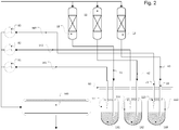
- the number of parallelized units is set to three for reasons of clarity. This is not limiting for the present invention.
- the device shown schematically comprises three reactors 11, 12, 13.
- a catalyst sample 21, 22, 23 to be tested is installed in each of these three reactors 11, 12, 13.
- the three reactors are supplied with starting material via a common inlet 30. This means that all catalysts 21, 22, 23 are charged with the same starting material.
- the reactors 11, 12, 13 can be heated or cooled and can be provided with a respective pressure maintenance. All this is not shown in the interest of simplicity. Different geometrical arrangements of the reactors are also possible, for example in order to generate different temperature control clusters.
- the catalyst samples to be tested in the reactors 21, 22, 23 can differ and can be compared in terms of their performance in the reactions.
- the product mixtures formed in the reactors leave the reactors 11, 12 and 13 via the dedicated processes 41, 42, 43. Since a gas / liquid phase reaction is carried out in each of the reactors 11, 12, 13, the respective product in the Also rule on gaseous and liquid fractions.
- the drains 41, 42, 43 are connected in a fluid-conducting manner to outlet cannulas 51, 52, 53 via flexible hose lines.
- the outlet cannulas are rigid, pointed hollow needles, at the pointed end of which the educts of the respective reactors constantly emerge.
- the starting material from the second catalyst 22 thus emerges from the second outlet cannula 52.
- the three outlet cannulas are combined in a block 60.
- the outlet cannulas can be immovable or movable relative to one another.
- Three exhaust gas cannulas 71, 72, 73 are also integrated into block 60. Each exhaust gas cannula is assigned to exactly one outlet cannula and vice versa; in the drawing corresponding to the last digit of the reference symbol. There is therefore also a clear assignment of the exhaust gas cannulas 71, 72, 73 to the respective reactors 11, 12, 13.
- the exhaust gas cannulas are designed as rigid, pointed hollow needles.
- the exhaust gas cannulas 71, 72, 73 are each connected to a gas analysis device 81, 82, 83 in a fluid-conducting manner by way of example via lines.
- a gas analysis device 81, 82, 83 to the respective reactors 11, 12, 13.
- This illustration is to be understood as an example in order to clarify the course of the gaseous product streams obtained in the direction of the analysis.
- a number of gas analyzers corresponding to the number of reactors will not be used. Rather, the gaseous product streams obtained are fed to the analysis individually or in the form of a mixture. If gaseous product flows are fed individually, a multi-way valve can be installed between the exhaust gas cannulas 71, 72 and 73 so that they can be analyzed in order.
- the outlet cannulas 51, 52, 53 are in the park position. In this, the outlet cannulas pierce a septum 90 of an outlet 100. All of the outlet cannulas 51, 52, 53 emerging components are collected and disposed of together undifferentiated. In test mode, there is therefore no analysis of the starting materials which are generated using the tested catalysts 21, 22, 23.
- the gas analysis devices 81, 82, 83 are also inactive in the parking position operation. Their outlets are combined on the outlet 100, but no gas flows through them.
- the pierced septum 90 seals the outlet cannulas 51, 52, 53, so that no educt emerges outside the outlet 100.
- dedicated septa can also be provided at the outlet 100 (not shown).
- Each vial 111, 112, 113 is uniquely assigned to a reactor 11, 12, 13.
- the assignment in the drawing corresponds to the last digit of the reference symbol.
- the first vial 111 is assigned to the first reactor 11 and vice versa.
- the vials 111, 112, 113 are used only when sampling. This is in Figure 2 shown.
- the assigned outlet cannulas 51, 52, 53 and exhaust gas cannulas 71, 72, 73 pierce the respective septa 121, 122, 123 of the vials 111, 112, 113, which are assigned to the reactors 11, 12, 13, as well the outlet cannulas 51, 52, 53 and exhaust gas cannulas 71, 72, 73 are assigned.
- the third outlet cannula 53 and third exhaust gas cannula 73 pierce through the septum 123 of the third vial 113 which, like the third outlet cannula 53 and third exhaust gas cannula 73, is assigned to the third reactor 13.
- a phase separation of the product mixtures of the three reactors 11, 12, 13 now takes place in the vials 111, 112, 113:
- the liquid portions of the respective products 131, 132, 133 of the reactors 11, 12, 13 are therefore separated into the Vials 111, 112, 113 collected;
- the gaseous proportions of the respective products 141, 142, 143 of the reactors 11, 12, 13 emerge again from the vials 111, 112, 113 through the respective exhaust gas cannulas 71, 72, 73 and are analyzed in the respective gas analysis devices 81, 82, 83.
- the gaseous fractions of products 141, 142, 143 are therefore analyzed “online” in a dedicated manner and then disposed of together via outlet 100.
- the liquid portions of the product mixtures 131, 132, 133 remain in the vials 111, 112, 113.
- the analysis of the liquid products 131, 132, 133 takes place outside the device.
- the vials 111, 112, 113 with the liquid samples 131, 132, 133 to be analyzed are brought to an analysis device.
- the individual vials can be removed individually and also inserted individually into, for example, a sample collector of an analysis device.
- the vials are already in blocks during sampling, which can hold several vials - typically 8 to 64 bottles. This block is then inserted as a whole into the autosampler of the analyzer.
- the vials can typically be identified in two ways. Either each vial is marked, e.g. with a barcode. Alternatively, the block can also be marked and the identification of the individual sample bottle takes place as a combination of the identification of the block and the position of the autosample when sampling.
- the cannulas 51, 52, 53, 71, 72, 73 must first be in the park position (corresponding Figure 1 ) retracted and secured against unwanted movement in a further sampling position.
- the cannulas 51, 52, 53, 71, 72, 73 combined in block 60 are moved with a handling device, not shown here; In the simplest case, this is a linear robot with two axes, a first for right / left movement and a second for lowering and raising the cannulas.
- the robot can also be used to remove the vials 111, 112, 113 for presentation to the analysis laboratory (not shown).
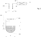
- the vials are used not only to collect the samples but also to separate the phases. This is in Figure 3 shown as an example.
- the vial (here representatively shown the first vial 111) has a cylindrical usable space N with the diameter d and the height h, the ratio h: d (slenderness ratio) being greater than 1.5.
- the vials are therefore relatively slim. In this respect, the drawings are not to scale.
- the cannulas 51, 71 assigned to the vial 111 run parallel to one another in a horizontal offset which is smaller than the diameter d. This distance must not be greater than d, since otherwise the pierced tip of the outlet cannula and the pierced tip of the exhaust gas cannula cannot be located within the usable space N in the sampling position. Furthermore, the horizontal offset should be greater than 11 mm in order to ensure that the septum remains sealed after the piercing. It is also possible to arrange both cannulas coaxially (not shown).
- both peaks are within the usable space during sampling and that there is a vertical offset v between the two peaks, the vertical offset v being between 0.6 * h to 0.8 * h.
- the device can be equipped with a magazine 150 which, in addition to a first set of vials 111, 112, 113, also comprises a second set of vials 161, 162, 163.
- each vial 111, 112, 113, 161, 162, 163 is also assigned to exactly one of the three reactors 11, 12, 13; again according to the last digit of the reference numbers.
- two vials are assigned to each reactor, for example vials 111 and 161 to the first reactor 11. The assignment is therefore not unambiguous here.
- the invention therefore also relates to the use of the device for testing heterogeneous catalysts in gas / liquid reactions or in liquid reactions in which gases are formed, a plurality of catalyst samples being tested simultaneously by assigning each catalyst sample to be tested to a reactor, so that the reaction takes place simultaneously on each catalyst sample to be tested, the products of the reactions taking place in the respective reactor exiting from the outlet cannula assigned to the respective reactor in the "sampling" state, a sample of the products of the reaction is taken in the respective vial, which takes place in the reactor which is assigned to the vial, a phase separation of the sample taking place during the sampling within the vial by the gas phase of the sample escaping through the pierced exhaust gas cannula and the liquid phase of the sample remaining in the vial.
- the device is suitable for use in all gas / liquid reactions known to those skilled in the art or in liquid reactions in which gases are produced, but also in pure liquid reactions.
- Examples of corresponding gas / liquid reactions are, in particular, hydrogenations and oxidations using appropriate gases.
- Examples of liquid reactions in which gases are known to the person skilled in the art are, in particular, decarbonylations, oxidations with hydrogen peroxide, dehydrogenations or cleavage reactions, for example the cleavage of MTBE.
- the device is preferably used in gas / liquid reactions, in particular in hydrogenations and oxidations, with hydrogenations being particularly preferred.
- Corresponding hydrogenation processes are known to the person skilled in the art and are accordingly carried out by processes known per se, for example in the temperature range from 150 ° C. to 200 ° C. at a pressure of 15 * 105 Pa to 30 * 105 Pa on a supported catalyst which is at least nickel and Contains copper, such as from EP3037400 known.
- hydrogenation catalysts consist of a support material based on titanium dioxide, zirconium dioxide, aluminum oxide, silicon oxide or their mixed oxides, with hydrogen-active metals, in particular at least one element from the group consisting of copper, cobalt, nickel, chromium, platinum, palladium and ruthenium, being applied to this support material.
- Aluminum oxide, aluminosilicate, silicon dioxide, titanium dioxide, zirconium dioxide can be used as the carrier precursor.
- a preferred carrier precursor is aluminum oxide, in particular ⁇ -aluminum oxide.
- the catalyst can contain one or more of the hydrogenation-active metals.
- the catalyst preferably contains the metals copper, chromium, nickel, platinum, palladium and ruthenium.
- the catalyst particularly preferably contains the combination of the three metals copper, chromium and nickel as the hydrogenation-active metal.
- the total content of hydrogenation-active metals, based on the reduced catalyst, is in the range from 1 to 40% by mass, in particular in the range from 5 to 25% by mass, calculated as metal.
- the content for precious metals is 0.1 - 5%.
- the catalysts are expediently produced in a form which offers low flow resistance when hydrogenated, such as tablets, cylinders, extrudates or rings.
- the support material is usually brought into the appropriate form. Molded support stock is also commercially available.
- conditions are set for the hydrogenation in which the product / starting phase is mainly in the liquid state, for example in the Liquid phase in three-phase reactors in cocurrent, the hydrogen being finely distributed in the liquid educt / product stream in a manner known per se.
- the hydrogenation is carried out with hydrogen in a pressure range from 5 to 100 bar, preferably between 5 and 40 bar, particularly preferably in the range from 10 to 25 bar.
- the hydrogenation temperatures are between 120 and 220 ° C, in particular between 140 and 190 ° C.
Landscapes
- Chemical & Material Sciences (AREA)
- Organic Chemistry (AREA)
- Chemical Kinetics & Catalysis (AREA)
- Sampling And Sample Adjustment (AREA)
Priority Applications (1)
| Application Number | Priority Date | Filing Date | Title |
|---|---|---|---|
| EP18210061.0A EP3662993A1 (fr) | 2018-12-04 | 2018-12-04 | Échantillonnage automatisé d'une installation d'essai de catalyseur parallélisée |
Applications Claiming Priority (1)
| Application Number | Priority Date | Filing Date | Title |
|---|---|---|---|
| EP18210061.0A EP3662993A1 (fr) | 2018-12-04 | 2018-12-04 | Échantillonnage automatisé d'une installation d'essai de catalyseur parallélisée |
Publications (1)
| Publication Number | Publication Date |
|---|---|
| EP3662993A1 true EP3662993A1 (fr) | 2020-06-10 |
Family
ID=64901289
Family Applications (1)
| Application Number | Title | Priority Date | Filing Date |
|---|---|---|---|
| EP18210061.0A Withdrawn EP3662993A1 (fr) | 2018-12-04 | 2018-12-04 | Échantillonnage automatisé d'une installation d'essai de catalyseur parallélisée |
Country Status (1)
| Country | Link |
|---|---|
| EP (1) | EP3662993A1 (fr) |
Cited By (1)
| Publication number | Priority date | Publication date | Assignee | Title |
|---|---|---|---|---|
| CN119688905A (zh) * | 2024-12-13 | 2025-03-25 | 北京卫星制造厂有限公司 | 一种co2催化转化生命保障验证系统 |
Citations (5)
| Publication number | Priority date | Publication date | Assignee | Title |
|---|---|---|---|---|
| US6534019B1 (en) * | 1998-12-24 | 2003-03-18 | Shimadzu Corporation | Automated chemical synthesizer |
| WO2005063372A2 (fr) | 2003-12-23 | 2005-07-14 | Hte Aktiengesellschaft The High Throughput Experimentation Company | Dispositif et procede de regulation de pression et de debit dans des reacteurs paralleles |
| US20050169815A1 (en) * | 2002-05-13 | 2005-08-04 | Avantium International B.V. | System for chemical experiments |
| WO2012178132A1 (fr) | 2011-06-24 | 2012-12-27 | Equilibar, Llc | Régulateur de contre-pression doté d'un support de joint flottant |
| EP3037400A1 (fr) | 2014-12-23 | 2016-06-29 | Evonik Degussa GmbH | Hydrogénation sans chrome de mélanges d'hydroformylation |
-
2018
- 2018-12-04 EP EP18210061.0A patent/EP3662993A1/fr not_active Withdrawn
Patent Citations (5)
| Publication number | Priority date | Publication date | Assignee | Title |
|---|---|---|---|---|
| US6534019B1 (en) * | 1998-12-24 | 2003-03-18 | Shimadzu Corporation | Automated chemical synthesizer |
| US20050169815A1 (en) * | 2002-05-13 | 2005-08-04 | Avantium International B.V. | System for chemical experiments |
| WO2005063372A2 (fr) | 2003-12-23 | 2005-07-14 | Hte Aktiengesellschaft The High Throughput Experimentation Company | Dispositif et procede de regulation de pression et de debit dans des reacteurs paralleles |
| WO2012178132A1 (fr) | 2011-06-24 | 2012-12-27 | Equilibar, Llc | Régulateur de contre-pression doté d'un support de joint flottant |
| EP3037400A1 (fr) | 2014-12-23 | 2016-06-29 | Evonik Degussa GmbH | Hydrogénation sans chrome de mélanges d'hydroformylation |
Cited By (1)
| Publication number | Priority date | Publication date | Assignee | Title |
|---|---|---|---|---|
| CN119688905A (zh) * | 2024-12-13 | 2025-03-25 | 北京卫星制造厂有限公司 | 一种co2催化转化生命保障验证系统 |
Similar Documents
| Publication | Publication Date | Title |
|---|---|---|
| EP0958496B1 (fr) | Dispositif et procede pour chromatographie en parallele | |
| DE19830607C2 (de) | Verfahren zum Nachweis eines Produktes im Abstrom eines katalytischen Materials einer Vielzahl von katalytischen Materialien | |
| DE69926845T2 (de) | Verfahren zum überwachen von gas(en) in einer dielektrischen flüssigkeit | |
| EP2110663B1 (fr) | Analyseur GC-MS commutable entre des types de fonctionnement unidimensionnel et bidimensionnel | |
| EP2577285B1 (fr) | Procédé de préparation d'échantillon pour séparation par chromatographie et appareil pour préparer un échantillon | |
| EP4028156B1 (fr) | Dispositif et procédé pour étudier des processus chimiques | |
| DE4412286A1 (de) | System zur kontaminationsfreien Bearbeitung von Reaktionsabläufen | |
| DE19712195A1 (de) | Verfahren und Vorrichtung zum off-line Nachweis von Analyten nach MALDI-Massenspektrometrie | |
| EP2046493B1 (fr) | Dispositif et procédé de manipulation de mélanges à composants multiples | |
| DE3833429A1 (de) | Kapillarmembranschnittstelle fuer massenspektrometer | |
| EP3242923B1 (fr) | Appareillage et procédé d'analyse de reformage du naphte | |
| DE2540969A1 (de) | Automatische probenvorbereitungsvorrichtung | |
| EP3662993A1 (fr) | Échantillonnage automatisé d'une installation d'essai de catalyseur parallélisée | |
| DE102007054420A1 (de) | Verfahren und Vorrichtung zur Isotopenverhältnisanalyse | |
| EP2690446B1 (fr) | Diviseur d'échantillon | |
| EP2210087B1 (fr) | Procédé et dispositif pour analyser les rapports isotopiques | |
| DE102010050599B4 (de) | Vorrichtung und Verfahren zur Testung von Katalysatoren mit verbesserter Prozessdruckeinstellung | |
| DE19652327C2 (de) | Verfahren und Vorrichtung zur Durchführung chemischer Reaktionsfolgen | |
| DE2523931A1 (de) | Verfahren und vorrichtung zur automatischen probenaufgabe bei einem flammenlosen atomabsorptionsspektrometer | |
| WO2008055585A1 (fr) | Procédé et dispositif de transfert continu et d'analyse de fluides | |
| DE2206004C3 (de) | Vorrichtung zur wahlweisen dosierten Entnahme von Fluiden aus einer Vielzahl verschiedener Fluidproben | |
| EP0925828A1 (fr) | Dispositif pour effectuer des réactions chimiques sequentielles | |
| DE102005049152B4 (de) | Verfahren zur Bereitstellung einer Substanz für die Analyse von Isotopenverhältnissen von C, N, S aus organischen Verbindungen sowie Einrichtung zur Durchführung einer Isotopenverhältnisanalyse | |
| DE102018114150A1 (de) | Mehrdimensional betreibbares Probentrenngerät mit gemeinsamem Fluidantrieb | |
| EP3287762A1 (fr) | Dispositif d'exposition aux aérosols et procédé d'exposition aux aérosols |
Legal Events
| Date | Code | Title | Description |
|---|---|---|---|
| PUAI | Public reference made under article 153(3) epc to a published international application that has entered the european phase |
Free format text: ORIGINAL CODE: 0009012 |
|
| STAA | Information on the status of an ep patent application or granted ep patent |
Free format text: STATUS: THE APPLICATION HAS BEEN PUBLISHED |
|
| AK | Designated contracting states |
Kind code of ref document: A1 Designated state(s): AL AT BE BG CH CY CZ DE DK EE ES FI FR GB GR HR HU IE IS IT LI LT LU LV MC MK MT NL NO PL PT RO RS SE SI SK SM TR |
|
| AX | Request for extension of the european patent |
Extension state: BA ME |
|
| STAA | Information on the status of an ep patent application or granted ep patent |
Free format text: STATUS: THE APPLICATION IS DEEMED TO BE WITHDRAWN |
|
| 18D | Application deemed to be withdrawn |
Effective date: 20201211 |