EP3663039A1 - Machine de polissage destinée au traitement d'une surface optique d'un verre de lunettes, dispositif de réception destiné à être utilisé dans la machine de polissage, procédé de traitement polissage des surfaces optiques des verres de lunettes et procédé de fabrication d'un verre de lunettes - Google Patents
Machine de polissage destinée au traitement d'une surface optique d'un verre de lunettes, dispositif de réception destiné à être utilisé dans la machine de polissage, procédé de traitement polissage des surfaces optiques des verres de lunettes et procédé de fabrication d'un verre de lunettes Download PDFInfo
- Publication number
- EP3663039A1 EP3663039A1 EP18209783.2A EP18209783A EP3663039A1 EP 3663039 A1 EP3663039 A1 EP 3663039A1 EP 18209783 A EP18209783 A EP 18209783A EP 3663039 A1 EP3663039 A1 EP 3663039A1
- Authority
- EP
- European Patent Office
- Prior art keywords
- elastic bearing
- polishing
- receiving
- polishing machine
- receiving device
- Prior art date
- Legal status (The legal status is an assumption and is not a legal conclusion. Google has not performed a legal analysis and makes no representation as to the accuracy of the status listed.)
- Granted
Links
Images


Classifications
-
- B—PERFORMING OPERATIONS; TRANSPORTING
- B24—GRINDING; POLISHING
- B24B—MACHINES, DEVICES, OR PROCESSES FOR GRINDING OR POLISHING; DRESSING OR CONDITIONING OF ABRADING SURFACES; FEEDING OF GRINDING, POLISHING, OR LAPPING AGENTS
- B24B13/00—Machines or devices designed for grinding or polishing optical surfaces on lenses or surfaces of similar shape on other work; Accessories therefor
- B24B13/005—Blocking means, chucks or the like; Alignment devices
-
- B—PERFORMING OPERATIONS; TRANSPORTING
- B24—GRINDING; POLISHING
- B24B—MACHINES, DEVICES, OR PROCESSES FOR GRINDING OR POLISHING; DRESSING OR CONDITIONING OF ABRADING SURFACES; FEEDING OF GRINDING, POLISHING, OR LAPPING AGENTS
- B24B13/00—Machines or devices designed for grinding or polishing optical surfaces on lenses or surfaces of similar shape on other work; Accessories therefor
- B24B13/0006—Machines or devices designed for grinding or polishing optical surfaces on lenses or surfaces of similar shape on other work; Accessories therefor for intraocular lenses
-
- B—PERFORMING OPERATIONS; TRANSPORTING
- B24—GRINDING; POLISHING
- B24B—MACHINES, DEVICES, OR PROCESSES FOR GRINDING OR POLISHING; DRESSING OR CONDITIONING OF ABRADING SURFACES; FEEDING OF GRINDING, POLISHING, OR LAPPING AGENTS
- B24B41/00—Component parts such as frames, beds, carriages, headstocks
- B24B41/007—Weight compensation; Temperature compensation; Vibration damping
-
- B—PERFORMING OPERATIONS; TRANSPORTING
- B24—GRINDING; POLISHING
- B24B—MACHINES, DEVICES, OR PROCESSES FOR GRINDING OR POLISHING; DRESSING OR CONDITIONING OF ABRADING SURFACES; FEEDING OF GRINDING, POLISHING, OR LAPPING AGENTS
- B24B41/00—Component parts such as frames, beds, carriages, headstocks
- B24B41/04—Headstocks; Working-spindles; Features relating thereto
-
- B—PERFORMING OPERATIONS; TRANSPORTING
- B24—GRINDING; POLISHING
- B24B—MACHINES, DEVICES, OR PROCESSES FOR GRINDING OR POLISHING; DRESSING OR CONDITIONING OF ABRADING SURFACES; FEEDING OF GRINDING, POLISHING, OR LAPPING AGENTS
- B24B13/00—Machines or devices designed for grinding or polishing optical surfaces on lenses or surfaces of similar shape on other work; Accessories therefor
-
- B—PERFORMING OPERATIONS; TRANSPORTING
- B24—GRINDING; POLISHING
- B24B—MACHINES, DEVICES, OR PROCESSES FOR GRINDING OR POLISHING; DRESSING OR CONDITIONING OF ABRADING SURFACES; FEEDING OF GRINDING, POLISHING, OR LAPPING AGENTS
- B24B13/00—Machines or devices designed for grinding or polishing optical surfaces on lenses or surfaces of similar shape on other work; Accessories therefor
- B24B13/01—Specific tools, e.g. bowl-like; Production, dressing or fastening of these tools
- B24B13/012—Specific tools, e.g. bowl-like; Production, dressing or fastening of these tools conformable in shape to the optical surface, e.g. by fluid pressure acting on an elastic membrane
-
- B—PERFORMING OPERATIONS; TRANSPORTING
- B24—GRINDING; POLISHING
- B24B—MACHINES, DEVICES, OR PROCESSES FOR GRINDING OR POLISHING; DRESSING OR CONDITIONING OF ABRADING SURFACES; FEEDING OF GRINDING, POLISHING, OR LAPPING AGENTS
- B24B13/00—Machines or devices designed for grinding or polishing optical surfaces on lenses or surfaces of similar shape on other work; Accessories therefor
- B24B13/02—Machines or devices designed for grinding or polishing optical surfaces on lenses or surfaces of similar shape on other work; Accessories therefor by means of tools with abrading surfaces corresponding in shape with the lenses to be made
-
- B—PERFORMING OPERATIONS; TRANSPORTING
- B24—GRINDING; POLISHING
- B24B—MACHINES, DEVICES, OR PROCESSES FOR GRINDING OR POLISHING; DRESSING OR CONDITIONING OF ABRADING SURFACES; FEEDING OF GRINDING, POLISHING, OR LAPPING AGENTS
- B24B41/00—Component parts such as frames, beds, carriages, headstocks
- B24B41/002—Grinding heads
Definitions
- the present invention relates to the field of optics and in particular to a polishing machine for processing an optical surface of a spectacle lens and a receiving device for use in the polishing machine.
- the invention further relates to a method for polishing an optical surface of an eyeglass lens and a method for producing an eyeglass lens with an optical surface.
- the industrial polishing of progressive lenses made of plastic or mineral materials is about removing machining structures such as micro-roughness, rotary grooves, grinding grooves, ripples and center defects of a free-form surface previously produced using the turning, milling or grinding process and thus surfaces with the required optical properties To generate properties.
- machining structures such as micro-roughness, rotary grooves, grinding grooves, ripples and center defects of a free-form surface previously produced using the turning, milling or grinding process and thus surfaces with the required optical properties To generate properties.
- a polishing head for polishing machines has a polishing plate which is connected to a drive shaft which can be driven in rotation.
- the polishing plate is articulated and non-rotatable with the drive shaft connected.
- a ball socket joint can be provided for the articulated, rotationally fixed connection. Due to the articulated connection, the polishing plate can follow the surface of the workpiece to be machined, for which the polishing surface always rests on a maximum area on the surface.
- a pressure chamber is also provided. A pressurization of the pressure chamber results in a translatory movement of the polishing plate along a central axis of the polishing head.
- a device for fine machining of optically effective surfaces, in particular spectacle lenses is known as workpieces.
- the device comprises a workpiece spindle projecting into a work space, via which a workpiece to be polished can be driven to rotate about a workpiece axis of rotation.
- the device furthermore has two tool spindles which are assigned to the workpiece spindle and project into the working area on the opposite side.
- a polishing tool can be driven on the tool spindles so as to rotate about a tool axis of rotation and is axially deliverable along the tool axis of rotation.
- the tool has a base body which has an active surface facing the optical surface. Furthermore, the tool has an intermediate layer arranged on the active surface of the base body and a polishing agent carrier arranged on the intermediate layer. The intermediate layer extends radially beyond the active surface of the base body. The polishing medium carrier projects radially beyond the intermediate layer.
- a polishing surface formed by a polishing agent carrier can adapt to a certain extent to a height profile of a glass to be processed in the axial direction.
- Freeform surfaces with a combination of a progressive progressive lens surface and a prescription surface with toric curvatures, which are placed on the back of the lens, represent a particular challenge in polishing. It is desirable to realize a highly precise machining that is as free of form errors as possible, with a machining time that is minimal for economic reasons and the use of simple, inexpensive polishing tools.
- the inventors have recognized that, in the case of devices known from the prior art, significant shape defects can occur during the polishing process, in particular in surface areas of a curved main torus axis of the glass, which deteriorate the quality of the manufactured product.
- the inventors have also recognized that in conventional polishing devices, in addition to an uneven removal distribution of the glass surface, vibrations and rattling of the polishing machine can occur as further disadvantageous effects. Vibration and chatter effects can also have a negative impact on the service life of the spindles and thus cause additional follow-up costs.
- an object of the present invention can be to provide a polishing machine for processing optical surfaces of spectacle lenses, which enables a more uniform removal of material during the polishing process.
- a polishing machine for processing an optical surface of a spectacle lens has two holding devices and an elastic bearing.
- Each of the two holding devices has a holding element for the reversible holding of a body.
- the elastic bearing is arranged between the two receiving devices.
- the elastic bearing can be arranged in a mechanical connection between the two receiving devices, which connects the two receiving devices to one another.
- a rigid coupling between two holding devices is considered advantageous, for example between a workpiece holder and a milling head.
- Such a rigid coupling ensures a high positional accuracy between the tool and the workpiece.
- Especially in the free-form processing of optical Surfaces can thus be ensured that the specified and the actual travel paths of the machine match.
- the inventors have recognized that a supposedly desirable very high positioning accuracy in a polishing machine for optical surfaces can have exactly the opposite effect. Instead, a damping coupling and thus a departure from the rigid coupling can be advantageous in a polishing machine. This is surprising insofar as the quality and dimensional accuracy of an optical surface can be improved by allowing larger path deviations instead of smaller path deviations of a processing machine. This can be achieved by the fact that in the proposed polishing machine an elastic bearing can now be provided between the two holding devices (e.g. tool holder and workpiece holder).
- At least one of the two receiving devices can have the elastic bearing.
- the elastic bearing can be arranged on or in a mechanical connection between the two receiving elements.
- the elastic bearing can be arranged between two rigid elements.
- One of the two rigid elements can be a first rigid element and the other rigid element can be a second rigid element.
- the first rigid element and / or the second rigid element can, for example, have a compression module selected from the group of at least 2 GPa, at least 35 GPa, at least 70 GPa, at least 100 GPa and at least 150 GPa.
- the first rigid element and / or the second rigid element can, for example, have an elastic modulus selected from the group of at least 1 GPa, at least 8 GPa, at least 50 GPa, at least 100 GPa, and at least 200 GPa.
- the first rigid element and / or the second rigid element can in particular be configured independently of a machine bed or machine frame.
- the first rigid element and / or the second rigid element can be set up to produce a reversible connection with a machine bed and / or with a machine frame.
- the elastic bearing can allow a relative movement between the two holding devices selected from the group from 1 ⁇ m to 10 cm, from 250 ⁇ m to 1 cm, and from 500 ⁇ m to 4 mm.
- a value from the group of 100 ⁇ m, 250 ⁇ m, 500 ⁇ m, 750 ⁇ m, 1 mm, 2 mm or 3 mm can optionally be selected as the lower limit.
- a value from the group of 1 cm, 7 mm, 5 mm, 3 mm, 2 mm or 1 mm can be selected as the upper limit.
- the relative movement can in particular be a range of motion.
- the relative movement can preferably be carried out perpendicular to an axis of a receiving device.
- the axis can be an axis of rotation for a rotary polishing movement of one of the receiving elements.
- One of the two holding devices can be designed for the reversible holding of a polishing tool and the other of the two holding devices can be designed for the reversible holding of a workpiece, in particular for the reversible holding of a spectacle lens.
- the elastic bearing can for example be a modulus of elasticity selected from the group of 0.5 N / mm 2 to 25 N / mm 2 , from 1.0 N / mm 2 to 2 N / mm 2 , and from 1.5 N / mm 2 have up to 2 N / mm 2 .
- the elastic bearing can have, for example, a compression module selected from the group of less than 2 GPa, less than 1 MPa, less than 1 kPa, and less than 1 Pa.
- the elastic bearing can, for example, be set up to guide a movement of a first element relative to a second element.
- the elastic bearing can be set up to guide a movement of the first rigid element relative to the second rigid element.
- At least one of the receiving elements can, for example, be set up to receive the respective body, for example a tool or a workpiece.
- the receiving element can be set up to reversibly connect the body to the receiving device, for example by means of a screw connection and / or by means of a clamp connection and / or by means of a click connection.
- a "reversible recording of the body” can in particular be understood to mean that the body can be connected and separated with the recording element without damaging the body and / or the recording element, preferably as often as desired.
- the inventors have recognized that even in a static case, an elastic tool that is subjected to pressure is compressed locally to different extents on an irregularly curved glass surface. Taking into account the locally different compression rate of the elastic tool and the resulting locally different pressure, a glass region located under a tool experiences a locally different pressure load depending on the curvature. Such an effect also has an analogous effect in a dynamic case of the ongoing polishing process. Specifically, this effect can result, for example, in local valleys in a concave or convex surface or those surfaces from which the polishing tool moves away always experiencing a lower pressure and thus also less polishing removal.
- this effect of the inhomogeneous compressive stress can be particularly pronounced with toric surfaces and with such free-form surfaces that have large radii of curvature, for example due to a large proportion of toric surfaces.
- height differences between a flat and a curved main axis in the outer area of the glass can be as much as several millimeters.
- a correspondingly compressed polishing tool which is subjected to the polishing pressure, is additionally compressed during one glass revolution in both strongly curved regions of the more curved main axis of the torus, twice per glass revolution. During a single glass revolution the tool thus describes an approximately sinusoidal height movement.
- the tool is therefore guided twice to the lowest and two times to the highest point of the respective radial position of the glass following the surface contour.
- a glass with higher toric surface areas rotates at a speed of, for example, 700 to 1000 rpm, resulting in a compression frequency of approximately 23 to 33 Hz.
- corresponding pressure peaks usually occur in the locally strongly curved areas of the glass .
- components of the pressure peaks acting at a high frequency perpendicular to a workpiece axis or axis of rotation, that is to say horizontal, are not taken into account in devices known from the prior art or are even cushioned by elements of the spindle construction. They act completely on the corresponding points on the glass surface and provide additional, highly undesirable material removal there.
- a polishing machine or a receiving device for a polishing machine wherein an elastic bearing can be arranged between two rigid elements, and the elastic bearing can be arranged on an opposite side from a receiving element.
- the polishing machine in particular at least one of the receiving devices, can be set up to compensate, for example, sideways-directed and / or high-frequency pressure peaks by means of a corresponding tilting movement.
- the laterally directed pressure peaks can be pressure peaks, for example, which act at an angle of 10 ° to 170 °, in particular 45 ° to 135 °, in particular 90 ° to an axis, for example an axis of symmetry or an axis of rotation of the receiving device. for example on the first rigid element and / or on the second rigid element.
- the high-frequency pressure peaks can be pressure peaks with a frequency of 5 Hz to 100 kHz, in particular from 10 Hz to 40 Hz, in particular from 23 Hz to 33 Hz.
- the polishing machine in particular at least one of the receiving devices, can also compensate for pressure peaks acting in the axial direction.
- the disclosed elastic bearing can in particular be a damping Have effect.
- horizontally directed pressure peaks can be absorbed elastically.
- the polishing machine in particular at least one of the receiving devices, can in particular be set up to reduce impacts and / or lateral force peaks on an eyeglass lens to be polished or an optical surface of an eyeglass lens and thus achieve a better surface quality.
- a higher material removal could be achieved in those places where a higher force acts during a polishing process.
- a shape of a high-precision free-form surface of a spectacle lens could be falsified again during the polishing process without an elastic bearing.
- the elastic bearing can in particular be set up to absorb airborne sound and / or structure-borne noise, in particular by converting kinetic energy into thermal energy, for example by friction effects within the elastic bearing.
- the elastic bearing can be set up to define a natural frequency of the receiving device in such a way that no resonance phenomena can occur or resonance phenomena can be suppressed by means of a rotational movement of the body or a motor of a polishing machine.
- vibrations can be damped by converting kinetic energy into thermal energy, for example by friction effects within the elastic bearing.
- a pick-up device for use in a polishing machine for processing an optical surface of a spectacle lens.
- the holding device has a holding element for the reversible holding of a body, in particular for the reversible holding of a spectacle lens.
- the receiving device can have an elastic bearing.
- the elastic bearing can be arranged between two rigid elements.
- a first rigid element of the two rigid elements can be arranged on a side of the elastic bearing facing the receiving element.
- a second rigid element of the two rigid elements can be arranged on a side of the elastic bearing facing away from the receiving element.
- the first body can be the spectacle lens.
- the second body can be the polishing tool.
- the method can further include the step of providing a polishing machine for processing an optical surface of a spectacle lens, the polishing machine having two receiving devices and an elastic bearing, each of the two receiving devices having a receiving element, the elastic bearing being arranged between the two receiving devices.
- a method for producing a spectacle lens with an optical surface is proposed, wherein a polishing treatment of the optical surface of the spectacle lens is carried out using the aforementioned method for polishing processing.
- the receiving device can, for example, be an essentially rotationally symmetrical device.
- the receiving device can have a layer structure along an axis of symmetry.
- the receiving device can be designed like a spindle, for example as a tool spindle or as a workpiece spindle.
- An optical surface can be understood to mean a front surface or surface of a spectacle lens on the object side.
- the front surface of a spectacle lens is the surface of a spectacle lens that is intended to face away from the eye in the spectacles.
- an optical surface can be understood to mean a rear surface or surface on the eye side of a spectacle lens.
- the back surface of a spectacle lens is the surface of a spectacle lens that is intended to face the eye in the glasses.
- the optical surfaces can be free-form surfaces, in particular toric free-form surfaces.
- a free-form surface is understood to mean a complex surface that is defined in particular by means of exclusively (in particular piecewise) polynomial functions (in particular polynomial splines, such as, for example, bikubic splines, higher-degree splines of the fourth degree or higher, Zernike polynomials, Forbes surfaces, Chebyshev Can represent polynomials, Fourier series, polynomial non-uniform rational B-splines (NURBS)).
- polynomial splines such as, for example, bikubic splines, higher-degree splines of the fourth degree or higher, Zernike polynomials, Forbes surfaces, Chebyshev Can represent polynomials, Fourier series, polynomial non-uniform rational B-splines (NURBS)).
- the freeform surface can also be a freeform surface in the narrower sense according to section 2.1.2 of DIN SPEC 58194 from December 2015, namely a surface made in freeform technology that is mathematically described within the limits of the differential geometry and is neither point nor axisymmetric.
- the free-form surface can have no point symmetry, no axis symmetry, no rotational symmetry and no symmetry with respect to a plane of symmetry.
- the optical surface can be a front and / or rear surface of a progressive spectacle lens made of plastic, for example made of CR39, polycarbonate, or a material with a higher refractive index.
- the optical surfaces can be surfaces of progressive lenses made of mineral materials.
- the optical surface can be a surface that is set up to change the optical properties of incident light, for example with respect to a direction of propagation.
- the receiving device can have the receiving element for reversibly receiving a body at one end of the receiving device.
- the expression “at one end” can in particular be understood to mean that the receiving element is a last element along an axis, for example an axis of rotation, of the receiving device.
- the receiving element can, for example, have at least one element selected from the group comprising a workpiece holder, clamping jaws, a click connection, a lens holder and a mirror holder.
- reversible receptacle can in particular be understood to mean that the body can be fixed to the receptacle element in such a way that the body can be released again without destroying the body or the receptacle device.
- the body can be a workpiece, for example.
- the body can be the workpiece with the optical surface to be machined.
- the body can be, for example, a lens or a mirror or some other optical element.
- the body can be a tool, for example a polishing tool.
- the body can be one in the DE 10 2013 220 973 A1 described tool for polishing optical surfaces.
- the body can thus comprise a base body which has an active surface facing the optical surface.
- the body can have an elastic intermediate layer arranged on the active surface of the base body and a polishing agent carrier arranged on the elastic intermediate layer.
- the elastic intermediate layer can project radially beyond the active surface of the base body and the polishing agent carrier can project radially beyond the elastic intermediate layer.
- a body can in particular be understood as a polishing tool.
- a body can also be understood to mean a spectacle lens.
- a first body can be a polishing tool and a second body can be a spectacle lens (with an optical surface to be machined).
- the elastic bearing can be arranged on the side of the receiving device opposite the receiving element.
- the side opposite the receiving element can in particular be a section furthest away from the receiving element, for example a half of the receiving device furthest away from the receiving element, in particular a third of the receiving device furthest away from the receiving element, in particular a quarter most distant from the receiving element Cradle, act.
- the elastic bearing can in particular at least partially, preferably completely, be arranged on the side opposite the receiving element.
- the receiving device can have the elastic bearing at the end opposite the receiving element.
- On the side opposite the receiving element can in particular be a side which is arranged opposite the body and the receiving element after the body has been received by the receiving element.
- the elastic bearing can be configured, for example, as an elastic layer.
- the elastic bearing can be designed to prevent or dampen vibrations.
- the elastic bearing can have an elastic and damping effect.
- the elastic bearing can allow, for example, a tilting movement of an underside of the elastic bearing relative to an upper side of the elastic bearing, in particular without deforming a surface of the underside of the elastic bearing and / or without deforming a surface of the upper side of the elastic bearing.
- the underside of the elastic bearing can point away from the receiving element.
- the top of the elastic bearing can point towards the receiving element.
- the elastic bearing can, for example, be an elastic base, in particular in order to serve as a barrier for vibrations to or from an environment.
- the elastic bearing can isolate the receiving device from vibrations from the environment.
- the elastic bearing can be arranged between two rigid elements.
- the elastic bearing can be arranged between a first rigid element and a second rigid element.
- the first rigid element and / or the second rigid element can be part of the receiving device.
- the first rigid element and / or the second rigid element can be part of the polishing machine.
- the first rigid element and / or the second rigid element can be part of an environment of the receiving device.
- the body is not one of the two rigid elements.
- the spectacle lens cannot be counted among the two rigid elements.
- the first rigid element and / or the second rigid element can be the receiving element.
- a rigid element can be an inelastic element.
- At least one of the two rigid elements, or both rigid elements can be configured such that an upper side and / or a lower side of the elastic bearing cannot be deformed.
- the first rigid element and / or the second rigid element can, for example, be a rigid one Act layer, for example made of metal.
- the first rigid element and / or the second rigid element can in particular be configured in such a way that when the elastic bearing is elastically deformed, the upper side and the underside of the elastic bearing are not (or not substantially) deformed.
- the top side can in particular be the side which points to the receiving element.
- the underside can preferably be the side which is opposite to the receiving element.
- the first rigid element and / or the second rigid element can cover the entire underside of the elastic bearing and / or the entire upper side of the elastic bearing.
- the first rigid element and / or the second rigid element can cover, for example, at least 80%, in particular at least 50%, in particular at least 30% of the upper side of the elastic bearing and / or the lower side of the elastic bearing.
- the first rigid element and / or the second rigid element can be an element which cannot move relative to the upper side of the elastic bearing and / or to the lower side of the elastic bearing.
- the first rigid element and / or the second rigid element can in particular be designed to prevent deformation of the upper side of the elastic bearing and / or the lower side of the elastic bearing.
- the polishing machine can be and / or have a horseshoe-shaped or U-shaped device.
- the elastic bearing can be arranged between the two arms of the U-shaped device or in a mechanical connection between the two arms.
- the first of the two holding devices can be arranged on a first of the two arms.
- the second of the two holding devices can be arranged on a second of the two arms.
- the elastic bearing can be arranged, for example, within the polishing tool holder or within the workpiece holder. Alternatively, the elastic bearing can be arranged outside the polishing tool holder or the polishing tool. For example, the elastic bearing can be arranged on a mechanical coupling between a holding device for holding the polishing tool and a holding device for holding the workpiece.
- the polishing machine can have connecting elements such as an arm.
- the connecting element or the arm can be designed to mechanically couple the two receiving devices to one another.
- the elastic bearing can be arranged in the connecting element or arm.
- the elastic bearing can be arranged such that an (elastic) lateral movement between a receiving element designed as a tool holder and a receiving element designed as a workpiece holder is made possible.
- the receiving element can be designed for the reversible receiving of a polishing tool and / or for the reversible receiving of a workpiece, for example a free-form surface, in particular a lens, in particular an eyeglass lens.
- the elastic bearing can in particular be set up to resolve a fixed positional relationship between the two rigid elements, for example between the polishing tool and a further receiving element and / or between the tool holder and the workpiece holder.
- the inventors have recognized that the greater play, which is caused by the elastic bearing, can advantageously reduce force peaks during the polishing of spectacle lenses, in particular when using optical free-form surfaces.
- the inventors have recognized that, in contrast to, for example, shaping processing, a highly precise positioning of the polishing tool holder relative to the workpiece holder does not have to be ensured in a method for polishing optical surfaces of eyeglass lenses, in particular not in every phase of the processing.
- the inventors have recognized that dodging, for example, a tool spindle compared to a workpiece spindle at the moment of a stress peak in precisely working milling, grinding or turning machines can lead to an undesirable form error on the workpiece.
- a vibration-damping coupling between a tool spindle and a workpiece spindle would be a disadvantage in contrast to a polishing machining.
- the inventors have particularly recognized that a slight evasive movement can or should be allowed during phases of extreme pressure peaks when polishing with an elastic, large-area polishing tool, for example with the polishing tool, in particular when polishing a free-form lens.
- the vibration-damping coupling of the polishing tool to the workpiece holder can even be advantageous. Short-term pressure peaks can be reduced by a possible evasive movement. Over the period of an entire polishing process, this can lead to a smaller form error compared to a rigid construction.
- the receiving device can be a polishing tool holder.
- the receiving element can be designed to reversibly receive a polishing tool.
- the receiving device can be an elastically mounted tool holder, for example for a polishing tool.
- the polishing tool holder can be drivable.
- the receiving device or a part of the receiving device, for example the receiving element can be drivable.
- at least a part of the receiving device can be drivable by a motor included in the receiving device or by an external motor.
- the receiving device, in particular the receiving element can be driven passively, for example by contact with a rotating device.
- the body can be a polishing plate for polishing, for example. In one embodiment, the body can be a polishing tool.
- the receiving element can be a receptacle for the polishing tool.
- the receiving device can be, for example, an elastically mounted tool holder for polishing machining of free-form surfaces.
- the receiving device can have a joint.
- the joint can be an element that is designed to reversibly change an angle between two elements of the receiving device.
- the angle can be fixed or fixable, for example, during a process for polishing. Alternatively, the angle may follow the topography of the optical surface during a polishing process.
- the joint can be a ball joint.
- the joint can be arranged between the receiving element and the elastic bearing.
- the joint can be arranged between the first rigid element and the receiving element.
- the joint can be arranged between the second rigid element and the receiving element.
- the first rigid element and / or the second rigid element can be part of the joint, in particular part of the joint, which cannot carry out a relative movement to the surface of the elastic bearing and / or to the underside of the elastic bearing.
- the receiving device can have a bellows.
- the bellows can be set up to protect the joint, for example from liquids or dust. Furthermore, the bellows can be set up to enable the joint to be moved.
- the bellows can, for example, be arranged between the receiving element and the elastic bearing. In particular, the bellows can be arranged between the first rigid element and the receiving element or between the second rigid element and the receiving element.
- the bellows can be arranged, for example, around the joint, in particular to protect the joint, for example from liquids or dust.
- the bellows can be the first rigid element and / or that include second rigid element.
- the first rigid element and / or the second rigid element can be set up to fix the bellows to the elastic bearing.
- the bellows can be arranged such that it serves to transmit a torque from a driven element, for example a driven tool spindle or a driven workpiece spindle, to the body, for example a polishing body or a workpiece.
- the receiving device can, for example, have a clamping device which is set up to fasten the receiving device to a drive unit.
- the drive unit can be a motor, in particular an electric motor.
- the clamping device can, for example, be set up to reversibly connect the receiving device to the drive unit.
- the receiving device can have a shaft for attachment to a spindle at the end opposite the receiving element.
- the elastic bearing can, for example, be arranged between the shaft and the joint or between the shaft and the bellows.
- the first rigid element and / or the second rigid element can be the shaft or the clamping device.
- the elastic bearing can be designed as a closed cell.
- the elastic bearing can, for example, have a structure that has a large number of cells or cavities.
- the elastic bearing can have essentially spherical cavities.
- the cavities can be close together or at least partially merge.
- the cavities can be filled with air or another gas, for example.
- the closed-cell elastic bearing can in particular essentially have cavities which are separated from one another. Cavities which are separated from one another can in particular have the effect that an air exchange between the cavities or between the elastic bearing and the environment is prevented or suppressed.
- the elastic bearing can have a closed-cell design such that a capillary action on liquids is suppressed or excluded. This can be particularly advantageous in order to prevent liquids, for example polishing paste, from entering the elastic bearing and the elastic bearing, for example. destroy or reduce the life of the elastic bearing.
- the elastic bearing can be sealed against liquids, in particular against polishing paste.
- At least one of the two receiving devices of the polishing machine can have an axis, for example.
- the term “axis” can be understood to mean a longitudinal axis.
- the longitudinal axis can indicate the direction of a greatest extent of the receiving device.
- the axis can be a virtual line.
- the axis can extend between the end with the receiving element and the side with the elastic bearing.
- the axis can be an axis of symmetry, for example.
- the axis can be a mirror symmetry axis or a rotational symmetry axis.
- the axis can be an axis of rotation.
- the axis can in particular be arranged parallel to a shaft or a spindle.
- the elastic bearing can in particular be designed to absorb forces perpendicular to the axis.
- the axis can be an axis of symmetry of the joint when the joint is fully extended.
- the elastic bearing can, for example, be designed to absorb both forces that act perpendicular to the axis and forces that act parallel to the axis.
- the elastic bearing can, for example, be set up to accommodate pressure peaks directed sideways.
- the elastic bearing can absorb forces which act via the ball joint on a side of the receiving device which is remote from the receiving element.
- the elastic bearing can in particular be designed to absorb and damp vibrations, the vibrations being able to act on the elastic bearing via the receiving element and / or from the environment.
- the elastic bearing can in particular be designed to absorb pressure peaks perpendicular to the axis.
- the receiving device can have a shaft, for example.
- the shaft can be set up to transmit a torque from the drive unit to the receiving device, in particular to the body.
- the shaft can, for example, be guided through a hole in the elastic bearing.
- the shaft can enter the receiving device from the end of the receiving device opposite the receiving element project, for example, up to the first rigid element or up to the elastic bearing or up to the second rigid element or up to the joint or up to the receiving element.
- the shaft can be drivable, for example, by the drive unit.
- the drive unit can, for example, drive the shaft at up to 1000 rpm.
- the elastic bearing can, for example, be set up to dampen an imbalance of the receiving device, in particular an imbalance of the shaft.
- the elastic bearing can, for example, be set up to convert kinetic energy into thermal energy, for example by means of friction effects.
- the elastic bearing can in particular be set up to dampen vibrations, in particular elastic vibrations, in particular by converting kinetic energy into thermal energy, for example by means of friction effects.
- the elastic bearing can in particular be set up to prevent the receiving device from being set into resonance vibrations, in particular by damping absorbed vibrations, for example by converting kinetic energy into thermal energy.
- the elastic bearing can be set up to define natural frequencies of the receiving device in such a way that they cannot be excited by means of vibrations that usually occur in an insert of the receiving device, for example by engine vibrations and / or ambient noise.
- the elastic bearing can in particular be set up to suspend the receiving device in a damping manner on another element, for example by converting kinetic energy, for example starting from a motor of a polishing machine, into thermal energy.
- the elastic bearing can, for example, cause a resilient suspension.
- the elastic bearing can in particular be a barrier to vibrations, for example transverse vibrations and / or longitudinal vibrations, for example by converting kinetic energy, for example starting from a motor of a polishing machine, into thermal energy.
- the elastic bearing can, for example, be designed to be anisotropic with regard to absorption of vibrations. For example, cavities of a foam may not be spherical and may be arranged in the center, which may result in different friction effects in different directions, for example.
- the elastic bearing may have a low compression modulus, as described above, and may therefore be suitable, for example, to be longitudinal Absorb vibrations.
- the elastic bearing can have a low modulus of elasticity, and can thus be suitable, for example, for absorbing transverse vibrations.
- the elastic bearing can have at least one element selected from the group consisting of foam, rubber, elastomer and a spring element.
- the foam can have closed-cell polyether urethane.
- the elastic bearing can, for example, be a foam mat, preferably a closed-cell, that is to say a closed-cell foam mat.
- the body can be a polishing tool, wherein the polishing tool can have an elastic layer.
- the elastic bearing can in particular be made of a different foam than the elastic layer.
- the elastic bearing can in particular have a stiffer foam than the elastic layer.
- the elastic layer of the polishing tool can consist of open-cell foam, in particular to absorb liquid, for example polishing paste, for example to ensure that there is always enough polishing paste on the optical surface during the polishing process.
- the use of closed-cell foam for the elastic bearing can serve in particular to prevent wear and / or to ensure a long service life of the elastic bearing.
- the elastic bearing can preferably be permanently fixed to the receiving device. In one embodiment, the elastic bearing cannot be separated from the rest of the receiving device without causing destruction of the elastic bearing or another element of the receiving device.
- the elastic bearing can be a rubber mat.
- the elastic bearing can be an elastomer damper.
- the spring element can, for example, be selected from the group comprising a spiral spring, a plate spring, and a gas pressure spring.
- the elastic bearing can be constructed, for example, from several of the materials mentioned, for example as a layer structure.
- the elastic bearing can be glued to at least one further element of the receiving device, preferably by means of an adhesive film.
- the elastic bearing can, for example, be glued to the first rigid element and / or to the second rigid element, in particular by means of the adhesive film.
- the adhesive film can, for example PSA (pressure-sensitive adhesive) film.
- the elastic bearing can, for example, be glued to the further element of the receiving device by a connection between foam and steel.
- only the top or only the bottom of the elastic bearing can be glued to another element. Both the top and the bottom of the elastic bearing can preferably be glued to a further element.
- the top side of the elastic bearing can particularly preferably be glued to the first rigid element and the bottom side of the elastic bearing can be glued to the second rigid element.
- the elastic bearing can be designed, for example, as a plate or a bush.
- the top of the elastic bearing can be aligned parallel to the underside of the elastic bearing when the elastic bearing is relaxed.
- the plate can have a hole, for example.
- the hole can be designed, for example, to guide a shaft, in particular for torque transmission, through the plate.
- a torque transmission can be made possible by the elastic bearing.
- the elastic bearing can, for example, be circular or ring-shaped, in particular with regard to a cross section perpendicular to the axis.
- the elastic bearing can be rotationally symmetrical, in particular around the hole.
- the cross section perpendicular to the axis of the elastic bearing can have the shape of a circular section or a ring section.
- the elastic bearing can have a thickness of at least 4 mm, in particular at least 20 mm, parallel to the axis.
- the elastic bearing can be a rubber bearing, for example.
- the elastic bearing can be a gimbal bushing.
- the elastic bearing can, for example, have a modulus of elasticity from the group of 0.5 N / mm 2 to 25 N / mm 2 , from 1.0 N / mm 2 to 2 N / mm 2 , and from 1.5 N / mm 2 have up to 2 N / mm 2 .
- the elastic bearing can have several zones with different modulus of elasticity.
- the elastic bearing can have two layers with different modulus of elasticity.
- the modulus of elasticity of the elastic bearing can in particular be selected such that optimal damping of vibrations, in particular damping of resonant vibrations, can be achieved.
- the modulus of elasticity can be selected in such a way that torque transmission via the elastic bearing can be ensured, in particular in cases in which the torque transmission takes place exclusively via the elastic bearing, that is to say for example without a shaft or torque transmission through the bellows.
- the holding device can, for example, be a workpiece holder.
- the receiving element can be designed for the reversible receiving of a workpiece, in particular for the reversible receiving of a spectacle lens.
- the workpiece holder can be drivable or non-drivable or passively drivable, for example.
- the body can be an eyeglass lens, for example.
- the receiving element can, for example, be set up to reversibly fix the spectacle lens or a lens to the receiving device, in particular for the duration of the polishing process.
- the receiving element can have a lens holder or a mirror holder.
- the receiving element can, for example, be designed to fix the lens, in particular the spectacle lens, by means of at least one screw.
- the holding device can be designed, for example, as a workpiece spindle.
- the proposed polishing machine can have, for example, the elastic bearing on the tool spindle or on the workpiece spindle, wherein the elastic bearing can be a non-positive structural element which acts elastically and dampens with respect to the pressure peak acting in the horizontal plane. It can be advantageous to mount the upper part of the tool holder on the elastic bearing in the form of a horizontally arranged plate made of a suitable foam material on the tool spindle.
- the elastic bearing can be set up to compensate for laterally directed, in particular high-frequency pressure peaks and / or pressure peaks acting in the axial direction by a corresponding tilting movement. Alternatively, a damping effect can be achieved with an elastic bushing. In both cases, in addition to foam mats, other construction elements and materials with elastic properties may also be conceivable as an elastic bearing.
- the elastic bearing can be designed, for example, as a compensating and damping element.
- the receiving device can, for example, be a non-drivable polishing tool holder.
- the receiving device can be a passively drivable receiving device, in particular by means of an opposite element, for example an opposite driven receiving device.
- the receiving device can have the following elements: a driven side of the tool spindle, the elastic bearing, for example designed as an elastic element for compensating sideways pressure peaks, a ball joint bearing with bellows for torque transmission, a polishing tool base body, and a polishing tool foam.
- the elements mentioned can, for example, be arranged in the order mentioned.
- the receiving device can be designed in particular for receiving spectacle lenses made of plastic materials.
- the proposed polishing machine can have a receiving device as described above.
- the polishing machine can be set up in particular for the polishing processing of free-form spectacle lenses.
- the polishing machine can have two or more of the proposed holding devices.
- the elastic bearing can in particular be set up to elastically couple the two receiving devices to one another.
- At least one of the two holding devices can be reversibly connected to a machine frame.
- the at least one receiving device can be mechanically coupled to the machine frame or can be coupled.
- the polishing machine can have a holding device as a workpiece holder and / or a holding device as a polishing tool holder.
- the polishing machine can also have only one holding device as a tool holder.
- the polishing machine can comprise the body or bodies, in particular the polishing tool.
- the polishing machine can have a work table or a CNC machine.
- the polishing machine can have two oppositely arranged or opposite receptacles, the axes of the receptacle being displaced or being displaceable relative to one another.
- the axes of the holding devices can be arranged parallel to one another.
- the polishing machine can be configured, for example, to rotate a rotating tool, in particular the one, to which a defined pressure is applied Polishing tool to guide over a rotating glass surface, for example the spectacle lens, optionally with the help of a polishing suspension.
- the polishing machine can in particular be designed to generate a defined relative movement between the optical surface and the tool, for example the polishing tool.
- the polishing machine can have a control device, for example.
- the control device can be set up to carry out the proposed method for polishing at least partially.
- One of the two rigid elements can be at least part of the arm of the polishing machine. Both rigid elements can preferably be parts of the arm of the polishing machine.
- the elastic bearing can preferably be irreversibly connected to the two rigid elements.
- the elastic bearing can be irreversibly connected to the arm of the polishing machine.
- the elastic bearing can be designed to elastically support at least one of the two receiving devices with respect to the arm.
- the arm can, for example, be firmly connected to a machine frame.
- the polishing machine can be designed such that at least one of the two holding devices is reversibly connected to a remaining part of the polishing machine.
- At least one of the two rigid elements can be configured to implement a reversible connection to a machine bed and / or a machine frame.
- the inventors have recognized that, in contrast to, for example, one in the method for polishing optical surfaces of spectacle lenses shaping processing, especially in a milling process, a turning process or a grinding process, precise guidance from tool to workpiece is not required to the same extent.
- a tolerance range for a path deviation in methods for polishing optical surfaces of eyeglass lenses can be approximately 1 mm and thus up to a factor of 1000 larger than in shaping processing.
- the elastic bearing can preferably be designed independently of a machine bed and / or a machine frame.
- the two rigid elements cannot be part of the machine frame and / or the machine bed.
- the two rigid elements and / or at least one of the two holding devices can only be reversibly connected or connectable to the machine bed or the machine frame.
- the method for polishing processing can also have one or more further steps, for example applying polishing paste or water to the polishing machine, in particular the polishing tool.
- the removal of material from a glass surface in particular organic glass materials, can be approximately 8 ⁇ m to 10 ⁇ m. With mineral materials, a material removal can be 15 ⁇ m to 20 ⁇ m.
- the machine can be set up so that the amplitude of an elastic movement permitted by the elastic bearing is greater than a height of a material removal provided by the polishing processing.
- the machine can be set up so that the amplitude of the elastic movement permitted by the elastic bearing in the lateral direction is greater than a height of material removal in the vertical direction, in particular greater than a height of a maximum material removal when polishing a spectacle lens.
- a material removal of each surface element of the surface which arises in the process for polishing processing can depend on various, locally active physical factors.
- the factors that determine this can be the relative speed between the glass and the polishing tool, a local machining pressure and a local surface curvature.
- Material properties of the glass, the polishing tool and the polishing suspension can be regarded as constant in the sense of the process.
- a material removal can be the integral of a local
- the removal rate corresponds to the polishing time, which can be proportional to the product of the local relative speeds and the local processing pressure in accordance with the so-called Preston equation.
- a proportionality factor is summarized in the Preston constant.
- the local relative speeds can be approximately determined using model calculations and can be largely regulated to constant values via the variable glass and tool speeds and oscillation movements, for example by means of the control device.
- a set machining pressure can, for example, act globally on a flat polishing tool.
- the optical surface can in particular be polished in such a way that an evasive movement between the two receiving devices can be carried out by means of the elastic bearing.
- the proposed solution can have numerous advantages. For example, a higher accuracy and surface quality when polishing optical surfaces can be achieved by means of the receiving device and / or by means of the polishing machine and / or by means of the method of polishing processing.
- a damping effect can also be achieved. For example, resonance frequencies can be prevented from being excited. This can lead to a reduction in noise, for example. Furthermore, a reduced service life resulting from resonance vibrations of at least one element of the polishing machine can be prevented. Furthermore, noise emission can be optimized, in particular reduced.
- Fig. 1 shows a part of an embodiment of a polishing machine 36.
- the polishing machine 36 has two receiving devices 10 and an elastic bearing 14.
- Each of the two holding devices 10 has a holding element 12 for the reversible holding of a body 42.
- the elastic bearing 14 is arranged between the two receiving devices 10.
- the exemplary embodiment shown of a receiving device 10 for an exemplary embodiment of a polishing machine 36 for processing optical surfaces of spectacle lenses has, in particular at one end, a receiving element 12 for reversibly receiving a body 42.
- the body 42 can in particular be designed as a polishing tool 44.
- the polishing tool 44 can have an elastic layer 46, for example.
- the polishing tool 44 can also have a polishing plate 48.
- the elastic layer 46 can in particular be designed in order to achieve an adaptation of the polishing plate 48 to the optical surface of the spectacle lens during the method.
- the polishing plate 48 is preferably designed such that the surface of the polishing tool 44 can adapt to the optical surface 62 of the spectacle lens.
- the receiving device 10 has an elastic bearing 14.
- the elastic bearing 14 can have, for example, foam 26, in particular an elastic foam layer, which can be circular or ring-shaped.
- the elastic foam layer can preferably be closed-cell.
- the top and / or bottom of the foam layer can be glued, for example.
- the elastic bearing 14 is arranged between two rigid elements 38 and 40.
- the elastic bearing 14 can in particular be glued to the top with a first rigid element 38 and an underside of the elastic bearing 14 can be glued to a second rigid element 40.
- the receiving device 10 as a whole can be designed as a polishing tool holder 34.
- the elastic bearing 14 can be arranged on the side opposite the receiving element 12.
- the receiving device 10 can have a joint 16.
- the joint 16 can have a ball pin 50 and a ball socket 52.
- the joint 16 can be arranged between the receiving element 12 and the elastic bearing 14.
- the receiving device 10 can have a bellows 18.
- the bellows 18 can be arranged between the receiving element 12 and the elastic bearing 14.
- the bellows 18 can in particular be a rubber bellows.
- the bellows 18 can be designed to transmit a torque.
- the holding device 10 shown can in particular be an elastically mounted tool holder for polishing machining of free-form surfaces.
- the receiving element 12 can, for example, be a receptacle for a polishing tool 44.
- the holding device 10 can have, for example, a lower part 54 of a tool holder.
- the first rigid element 38 can be the lower part 54 of the tool holder.
- the elastic bearing 14 can preferably be closed-cell.
- the receiving device 10 can have an axis 24.
- the axis 24 can in particular be an axis of rotation.
- the elastic bearing 14 can be designed to absorb forces perpendicular to the axis 24.
- the holding device 10 can, for example, have a spindle 22, in particular a driven tool spindle 56.
- the receiving device 10 can be set up to be connected to a driven tool spindle 56.
- the tool spindle 56 can be fastened to the holding device 10 by means of a clamping device 58.
- the Clamping device 58 can in particular also be designed to fasten the complete tool carrier.
- the top of the elastic bearing 14 and / or the underside of the elastic bearing 14 can be glued to the first rigid element 38 and / or to the second rigid element 40, for example by means of a PSA adhesive film 60.
- the upper side of the elastic bearing 14 can point in particular in the direction of the receiving element 12.
- the underside can in particular point away from the receiving element 12.
- the receiving device 10 can have a shaft 32, for example.
- the elastic bearing 14 can be set up to dampen vibrations.
- the elastic bearing 14 can be glued to at least one further element of the receiving device 10, preferably by means of an adhesive film 28.
- the elastic bearing 14 can preferably be designed as a plate 30.
- the elastic bearing 14 can have a modulus of elasticity of 0.5 N / mm 2 to 25 N / mm 2 , in particular from 1.0 N / mm 2 to 2 N / mm 2 , in particular from 1.5 N / mm 2 to 2 N / mm 2 .
- Fig. 2 shows a further exemplary embodiment of a polishing machine 36.
- the polishing machine 36 can be or comprise a horseshoe-shaped or a U-shaped device.
- the elastic bearing 14 can be set up in order to couple the two receiving devices 10 to one another, in particular in a vibration-damping and / or elastic manner.
- a receiving element 12 of the polishing machine 36 can be a polishing tool holder 34.
- Another receiving element 86 of the polishing machine can be designed to reversibly receive an eyeglass lens.
- the further receiving element 68 can be a workpiece holder 64, for example.
- the exemplary embodiment shown of a polishing machine 36 for processing optical surfaces of spectacle lenses has, in particular at one end, a receiving element 12 for reversibly receiving a body 42.
- the body 42 can in particular be designed as a polishing tool 44.
- the polishing tool 44 can have an elastic layer 46, for example.
- the polishing tool 44 can also have a polishing plate 48.
- the elastic layer 46 can be designed in particular in order to achieve an adaptation of the polishing plate 48 to the spectacle lens during the method.
- the polishing plate 48 is preferably designed such that the surface of the polishing tool 44 can adapt to the optical surface 62 of the spectacle lens.
- the polishing machine 36 has an elastic bearing 14.
- the elastic bearing 14 can have, for example, foam 26, in particular an elastic foam layer, which can be circular or ring-shaped.
- the elastic foam layer can preferably be closed-cell.
- the top and / or the bottom of the foam layer can be glued, for example, for example by means of an adhesive film 28.
- the elastic bearing 14 is arranged between two rigid elements 38 and 40, which can be part of an arm of the polishing machine 36, for example.
- the elastic bearing 14 can in particular be glued to the top with a first rigid element 38 and an underside of the elastic bearing 14 can be glued to a second rigid element 40.
- the polishing machine 36 can have a polishing tool holder 34 and a workpiece holder 68.
- At least one of the two receiving devices 10 can have a joint 16.
- the joint 16 can have a ball pin and a ball socket.
- the joint 16 can be arranged between the receiving element 12 and a shaft 32.
- At least one of the two receiving devices 10 can have a bellows 18.
- the bellows 18 can in particular be a rubber bellows.
- the bellows 18 can be designed to transmit a torque.
- Shown devices 10 shown can in particular be an elastically mounted tool holder for polishing free-form surfaces.
- the receiving element 12 can, for example, be a receptacle for a polishing tool 44.
- the elastic bearing 14 can preferably be closed-cell. At least one of the two receiving devices 10, preferably both receiving devices 10, can have an axis 24. The axis 24 can in particular be an axis of rotation.
- the elastic bearing 14 can be designed to absorb forces perpendicular to the axis 24.
- the holding device 10 can, for example, have a spindle, in particular a driven tool spindle. Alternatively, the receiving device 10 can be set up to be connected to a driven tool spindle. For example, the tool spindle can be fastened to the holding device 10 by means of a clamping device. The clamping device can in particular also be designed for fastening the complete tool carrier.
- the top of the elastic bearing 14 and / or the underside of the elastic bearing 14 can be glued to the first rigid element 38 and / or to the second rigid element 40, for example by means of a PSA adhesive film 60.
- the upper side of the elastic bearing 14 can point in particular in the direction of the receiving element 12.
- the underside can in particular point away from the receiving element 12.
- the underside can point to the further receiving element 68, in particular along the horseshoe-shaped device.
- the receiving device 10 can have a shaft 32, for example.
- the elastic bearing 14 can be set up to dampen vibrations.
- the elastic bearing 14 can be glued to at least one further element of the receiving device 10, preferably by means of an adhesive film 28.
- the elastic bearing 14 can preferably be designed as a plate 30.
- the elastic bearing 14 can have a modulus of elasticity of 0.5 N / mm 2 to 25 N / mm 2 , in particular from 1.0 N / mm 2 to 2 N / mm 2 , in particular from 1.5 N / mm 2 to 2 N / mm 2 .
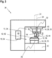
- Fig. 3 shows a further embodiment of a polishing machine 36 for processing an optical surface of an eyeglass lens 62.
- the optical surface 62 can, for example, be a front and / or rear surface of an eyeglass lens, in particular a free-form eyeglass lens.
- the polishing machine 36 can have a receiving device 10, as described above.
- the polishing machine 36 like the polishing machine 36 in Fig. 2 , Two exemplary embodiments of the receiving devices 10.
- the polishing machine 36 can have a holding device 10 as a polishing tool holder 34, in particular a holding device 10 as already shown in FIG Fig. 1 shown and described above.
- the polishing machine 36 can have a holding device 10 as in FIG Fig. 2 have shown.
- the polishing machine 36 can have a holding device 10 as a workpiece holder 64.
- the receiving device 10 as a polishing tool holder 34 can receive the polishing tool 44 as a body 42.
- the holding device 10 as the workpiece holder 64 can hold the spectacle lens with the optical surface or the lens 62 as the body 42.
- the polishing machine 36 can, for example, have further holding devices 10, for example a total of four holding devices 10, for example to polish two spectacle lenses in parallel.
- Both receiving devices 10 can, for example, be arranged opposite one another.
- Axes 24 of the two holding devices 10 can be arranged, for example, in parallel, but shifted from one another.
- the axes 24 can be displaceable.
- the polishing machine 36 can have a control device 66, for example.
- the control device 66 can be designed, for example, to regulate a number of revolutions and / or pressurization.
- the polishing machine can have at least one clamping device 58, for example for the reversible fastening of a holding device 10.
- the polishing machine can preferably have two clamping devices 58 for the reversible fastening of two holding devices 10.
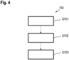
- Fig. 4 shows a flow diagram of a method 100 for the polishing processing of an optical surface 62 of a spectacle lens.
- a polishing machine 36 can be provided, as described above.
- the polishing machine 36 can have two holding devices 10 and an elastic bearing 14.
- Each of the two receiving devices 10 can have a receiving element 12.
- the elastic bearing 14 can be arranged between the two receiving devices 10.
- a first and a second body 42 such as an eyeglass lens with a surface 62 to be polished and a polishing tool 44, are picked up by means of two elastically connected holding devices 10.
- the first body can have or be the spectacle lens 62.
- the second body may have or be a polishing tool 44.
- the optical surface 62 of the spectacle lens is polished with the polishing tool 44 or with the polishing machine 36.
- the control device 66 can be used in the method to regulate the polishing processing, for example to regulate a rotational frequency or a pressurization or a relative movement of the two receiving elements 12 or an application of polishing paste or water.
- advantages of the solutions proposed here in particular thanks to the improved damping during the polishing process, can consist in further improving the surface quality of an eyeglass lens and in particular in enabling a more uniform material removal during the polishing process.
Landscapes
- Engineering & Computer Science (AREA)
- Mechanical Engineering (AREA)
- Health & Medical Sciences (AREA)
- General Health & Medical Sciences (AREA)
- Ophthalmology & Optometry (AREA)
- Grinding And Polishing Of Tertiary Curved Surfaces And Surfaces With Complex Shapes (AREA)
Priority Applications (1)
| Application Number | Priority Date | Filing Date | Title |
|---|---|---|---|
| EP18209783.2A EP3663039B1 (fr) | 2018-12-03 | 2018-12-03 | Machine de polissage destinée au traitement d'une surface optique d'un verre de lunettes, procédé de traitement polissage des surfaces optiques des verres de lunettes et procédé de fabrication d'un verre de lunettes |
Applications Claiming Priority (1)
| Application Number | Priority Date | Filing Date | Title |
|---|---|---|---|
| EP18209783.2A EP3663039B1 (fr) | 2018-12-03 | 2018-12-03 | Machine de polissage destinée au traitement d'une surface optique d'un verre de lunettes, procédé de traitement polissage des surfaces optiques des verres de lunettes et procédé de fabrication d'un verre de lunettes |
Publications (3)
| Publication Number | Publication Date |
|---|---|
| EP3663039A1 true EP3663039A1 (fr) | 2020-06-10 |
| EP3663039C0 EP3663039C0 (fr) | 2025-02-05 |
| EP3663039B1 EP3663039B1 (fr) | 2025-02-05 |
Family
ID=64572189
Family Applications (1)
| Application Number | Title | Priority Date | Filing Date |
|---|---|---|---|
| EP18209783.2A Active EP3663039B1 (fr) | 2018-12-03 | 2018-12-03 | Machine de polissage destinée au traitement d'une surface optique d'un verre de lunettes, procédé de traitement polissage des surfaces optiques des verres de lunettes et procédé de fabrication d'un verre de lunettes |
Country Status (1)
| Country | Link |
|---|---|
| EP (1) | EP3663039B1 (fr) |
Cited By (1)
| Publication number | Priority date | Publication date | Assignee | Title |
|---|---|---|---|---|
| CN120395597A (zh) * | 2025-06-12 | 2025-08-01 | 玉环凯立汽车配件股份有限公司 | 一种用于vvt链轮的浮动式轴向倒角控制系统 |
Citations (10)
| Publication number | Priority date | Publication date | Assignee | Title |
|---|---|---|---|---|
| DE1235179B (de) * | 1961-07-03 | 1967-02-23 | American Optical Corp | Fuehrungseinrichtung fuer das Schleifen torischer Linsen mittels eines rotierenden, der herzustellenden Torusflaeche entsprechenden Werkzeuges |
| WO1989004986A1 (fr) | 1987-11-25 | 1989-06-01 | Optische Werke G. Rodenstock | Verre progressif pour lunettes |
| DE3934180A1 (de) * | 1988-10-20 | 1990-04-26 | Olympus Optical Co | Haltevorrichtung fuer die halterung eines zu schleifenden optischen elements |
| US5291692A (en) * | 1989-09-14 | 1994-03-08 | Olympus Optical Company Limited | Polishing work holder |
| DE19926414A1 (de) * | 1999-06-10 | 2000-12-21 | Optotech Optikmasch Gmbh | Kombiwerkzeug zum Bearbeiten optischer Linsen |
| DE10100860A1 (de) | 2000-02-03 | 2001-08-23 | Zeiss Carl | Polierkopf für eine Poliermaschine |
| US7033261B2 (en) * | 2002-01-16 | 2006-04-25 | Essilor International (Compagnie Generale D'optique) | Tool for surface treatment of an optical surface |
| DE102013220973A1 (de) | 2013-10-16 | 2015-04-16 | Carl Zeiss Vision International Gmbh | Werkzeug zur Polierbearbeitung von optischen Flächen |
| DE102014015053A1 (de) | 2014-10-15 | 2016-04-21 | Satisloh Ag | Vorrichtung zur Feinbearbeitung von optisch wirksamen Flächen an insbesondere Brillengläsern |
| DE202015009504U1 (de) * | 2014-10-15 | 2018-01-16 | Satisloh Ag | Polierteller für ein Werkzeug zur Feinbearbeitung von optisch wirksamen Flächen an Brillengläsern |
-
2018
- 2018-12-03 EP EP18209783.2A patent/EP3663039B1/fr active Active
Patent Citations (10)
| Publication number | Priority date | Publication date | Assignee | Title |
|---|---|---|---|---|
| DE1235179B (de) * | 1961-07-03 | 1967-02-23 | American Optical Corp | Fuehrungseinrichtung fuer das Schleifen torischer Linsen mittels eines rotierenden, der herzustellenden Torusflaeche entsprechenden Werkzeuges |
| WO1989004986A1 (fr) | 1987-11-25 | 1989-06-01 | Optische Werke G. Rodenstock | Verre progressif pour lunettes |
| DE3934180A1 (de) * | 1988-10-20 | 1990-04-26 | Olympus Optical Co | Haltevorrichtung fuer die halterung eines zu schleifenden optischen elements |
| US5291692A (en) * | 1989-09-14 | 1994-03-08 | Olympus Optical Company Limited | Polishing work holder |
| DE19926414A1 (de) * | 1999-06-10 | 2000-12-21 | Optotech Optikmasch Gmbh | Kombiwerkzeug zum Bearbeiten optischer Linsen |
| DE10100860A1 (de) | 2000-02-03 | 2001-08-23 | Zeiss Carl | Polierkopf für eine Poliermaschine |
| US7033261B2 (en) * | 2002-01-16 | 2006-04-25 | Essilor International (Compagnie Generale D'optique) | Tool for surface treatment of an optical surface |
| DE102013220973A1 (de) | 2013-10-16 | 2015-04-16 | Carl Zeiss Vision International Gmbh | Werkzeug zur Polierbearbeitung von optischen Flächen |
| DE102014015053A1 (de) | 2014-10-15 | 2016-04-21 | Satisloh Ag | Vorrichtung zur Feinbearbeitung von optisch wirksamen Flächen an insbesondere Brillengläsern |
| DE202015009504U1 (de) * | 2014-10-15 | 2018-01-16 | Satisloh Ag | Polierteller für ein Werkzeug zur Feinbearbeitung von optisch wirksamen Flächen an Brillengläsern |
Cited By (1)
| Publication number | Priority date | Publication date | Assignee | Title |
|---|---|---|---|---|
| CN120395597A (zh) * | 2025-06-12 | 2025-08-01 | 玉环凯立汽车配件股份有限公司 | 一种用于vvt链轮的浮动式轴向倒角控制系统 |
Also Published As
| Publication number | Publication date |
|---|---|
| EP3663039C0 (fr) | 2025-02-05 |
| EP3663039B1 (fr) | 2025-02-05 |
Similar Documents
| Publication | Publication Date | Title |
|---|---|---|
| DE69807032T2 (de) | Ophtalmische linse erzeugungsvorrichtung mit schwingungsdämpfungsanordnung | |
| EP2837464B1 (fr) | Procédé de polissage destiné au traitement d'une surface optique d'une lentille optique et outils de polissage appropriés | |
| DE102009005954B4 (de) | Dämpfungsvorrichtung | |
| EP3463751B1 (fr) | Procédé de polissage de lentilles | |
| EP3033196A1 (fr) | Machine permettant d'usiner des pièces | |
| DE102016004328A1 (de) | Werkzeugspindel für eine Vorrichtung zur Feinbearbeitung von optisch wirksamen Flächen an Werkstücken | |
| DE202015009504U1 (de) | Polierteller für ein Werkzeug zur Feinbearbeitung von optisch wirksamen Flächen an Brillengläsern | |
| EP1773539B1 (fr) | Procede et dispositif de traitement de surfaces de pieces optiques | |
| WO2017211452A1 (fr) | Machine d'usinage de pièces de qualité optique | |
| DE102016203116A1 (de) | Bearbeitungseinheit für eine Werkzeugmaschine und Werkzeugmaschine mit einer derartigen Bearbeitungseinheit | |
| DE102005052314A1 (de) | Fast-Tool-Anordnung, insbesondere für Drehmaschinen zur Bearbeitung von optischen Werkstücken | |
| EP1742762B1 (fr) | Dispositif pour produire des microstructures | |
| EP3663039B1 (fr) | Machine de polissage destinée au traitement d'une surface optique d'un verre de lunettes, procédé de traitement polissage des surfaces optiques des verres de lunettes et procédé de fabrication d'un verre de lunettes | |
| EP2825349B1 (fr) | Machine d'usinage de pièces optiques, en particulier de verres de lunettes en matière plastique | |
| DE102012108594A1 (de) | Vorrichtung zur Finishbearbeitung von Werkstücken | |
| EP3820685A1 (fr) | Procédé de production d'un système optique doté d'un élément optique constitué d'un matériau dur et fragile | |
| DE102014012354A1 (de) | Verfahren und Vorrichtung zur ultrapräzisen Bearbeitung einer Referenzfläche eines eine optische Achse aufweisenden Werkstücks | |
| DE60206518T2 (de) | Werkzeughaltevorrichtung für hochgenaue kalibrierung von löchern | |
| DE19701735A1 (de) | Verfahren und Vorrichtung zum Polieren von beliebigen Oberflächen | |
| DE202014009911U1 (de) | Multimaterial Blockstück | |
| DE102012216724A1 (de) | Verfahren und Vorrichtung zur Polierbearbeitung von Brillenlinsen und Gießformen für die Brillenlinsenherstellung sowie entsprechendes Verfahren zur Herstellung von Brillenlinsen und Gießformen für die Brillenlinsenherstellung | |
| WO2017001511A1 (fr) | Machine de fabrication de billes, billes et procédé de fabrication d'une bille | |
| DE3037999A1 (de) | Stossgedaempfte zentriereinrichtung fuer zwei- und vierrollen-fliessdruecksupporte | |
| DE19749428A1 (de) | Bearbeitungsvorrichtung für die 3D-Bearbeitung von optischen Glasrohlingen | |
| EP4271538B1 (fr) | Procédé et dispositif d'usinage de précision de lentilles axicon, machine d'usinage de précision appropriée et utilisation y relative |
Legal Events
| Date | Code | Title | Description |
|---|---|---|---|
| PUAI | Public reference made under article 153(3) epc to a published international application that has entered the european phase |
Free format text: ORIGINAL CODE: 0009012 |
|
| STAA | Information on the status of an ep patent application or granted ep patent |
Free format text: STATUS: THE APPLICATION HAS BEEN PUBLISHED |
|
| AK | Designated contracting states |
Kind code of ref document: A1 Designated state(s): AL AT BE BG CH CY CZ DE DK EE ES FI FR GB GR HR HU IE IS IT LI LT LU LV MC MK MT NL NO PL PT RO RS SE SI SK SM TR |
|
| AX | Request for extension of the european patent |
Extension state: BA ME |
|
| STAA | Information on the status of an ep patent application or granted ep patent |
Free format text: STATUS: REQUEST FOR EXAMINATION WAS MADE |
|
| 17P | Request for examination filed |
Effective date: 20201203 |
|
| RBV | Designated contracting states (corrected) |
Designated state(s): AL AT BE BG CH CY CZ DE DK EE ES FI FR GB GR HR HU IE IS IT LI LT LU LV MC MK MT NL NO PL PT RO RS SE SI SK SM TR |
|
| STAA | Information on the status of an ep patent application or granted ep patent |
Free format text: STATUS: EXAMINATION IS IN PROGRESS |
|
| 17Q | First examination report despatched |
Effective date: 20230706 |
|
| GRAP | Despatch of communication of intention to grant a patent |
Free format text: ORIGINAL CODE: EPIDOSNIGR1 |
|
| STAA | Information on the status of an ep patent application or granted ep patent |
Free format text: STATUS: GRANT OF PATENT IS INTENDED |
|
| INTG | Intention to grant announced |
Effective date: 20240906 |
|
| GRAS | Grant fee paid |
Free format text: ORIGINAL CODE: EPIDOSNIGR3 |
|
| GRAA | (expected) grant |
Free format text: ORIGINAL CODE: 0009210 |
|
| STAA | Information on the status of an ep patent application or granted ep patent |
Free format text: STATUS: THE PATENT HAS BEEN GRANTED |
|
| AK | Designated contracting states |
Kind code of ref document: B1 Designated state(s): AL AT BE BG CH CY CZ DE DK EE ES FI FR GB GR HR HU IE IS IT LI LT LU LV MC MK MT NL NO PL PT RO RS SE SI SK SM TR |
|
| REG | Reference to a national code |
Ref country code: GB Ref legal event code: FG4D Free format text: NOT ENGLISH |
|
| REG | Reference to a national code |
Ref country code: CH Ref legal event code: EP |
|
| REG | Reference to a national code |
Ref country code: DE Ref legal event code: R096 Ref document number: 502018015546 Country of ref document: DE |
|
| REG | Reference to a national code |
Ref country code: IE Ref legal event code: FG4D Free format text: LANGUAGE OF EP DOCUMENT: GERMAN |
|
| U01 | Request for unitary effect filed |
Effective date: 20250205 |
|
| U07 | Unitary effect registered |
Designated state(s): AT BE BG DE DK EE FI FR IT LT LU LV MT NL PT RO SE SI Effective date: 20250211 |
|
| PG25 | Lapsed in a contracting state [announced via postgrant information from national office to epo] |
Ref country code: RS Free format text: LAPSE BECAUSE OF FAILURE TO SUBMIT A TRANSLATION OF THE DESCRIPTION OR TO PAY THE FEE WITHIN THE PRESCRIBED TIME-LIMIT Effective date: 20250505 |
|
| PG25 | Lapsed in a contracting state [announced via postgrant information from national office to epo] |
Ref country code: PL Free format text: LAPSE BECAUSE OF FAILURE TO SUBMIT A TRANSLATION OF THE DESCRIPTION OR TO PAY THE FEE WITHIN THE PRESCRIBED TIME-LIMIT Effective date: 20250205 |
|
| PG25 | Lapsed in a contracting state [announced via postgrant information from national office to epo] |
Ref country code: ES Free format text: LAPSE BECAUSE OF FAILURE TO SUBMIT A TRANSLATION OF THE DESCRIPTION OR TO PAY THE FEE WITHIN THE PRESCRIBED TIME-LIMIT Effective date: 20250205 |
|
| PG25 | Lapsed in a contracting state [announced via postgrant information from national office to epo] |
Ref country code: NO Free format text: LAPSE BECAUSE OF FAILURE TO SUBMIT A TRANSLATION OF THE DESCRIPTION OR TO PAY THE FEE WITHIN THE PRESCRIBED TIME-LIMIT Effective date: 20250505 Ref country code: IS Free format text: LAPSE BECAUSE OF FAILURE TO SUBMIT A TRANSLATION OF THE DESCRIPTION OR TO PAY THE FEE WITHIN THE PRESCRIBED TIME-LIMIT Effective date: 20250605 |
|
| PG25 | Lapsed in a contracting state [announced via postgrant information from national office to epo] |
Ref country code: HR Free format text: LAPSE BECAUSE OF FAILURE TO SUBMIT A TRANSLATION OF THE DESCRIPTION OR TO PAY THE FEE WITHIN THE PRESCRIBED TIME-LIMIT Effective date: 20250205 |
|
| PG25 | Lapsed in a contracting state [announced via postgrant information from national office to epo] |
Ref country code: GR Free format text: LAPSE BECAUSE OF FAILURE TO SUBMIT A TRANSLATION OF THE DESCRIPTION OR TO PAY THE FEE WITHIN THE PRESCRIBED TIME-LIMIT Effective date: 20250506 |
|
| PG25 | Lapsed in a contracting state [announced via postgrant information from national office to epo] |
Ref country code: SM Free format text: LAPSE BECAUSE OF FAILURE TO SUBMIT A TRANSLATION OF THE DESCRIPTION OR TO PAY THE FEE WITHIN THE PRESCRIBED TIME-LIMIT Effective date: 20250205 |
|
| PG25 | Lapsed in a contracting state [announced via postgrant information from national office to epo] |
Ref country code: CZ Free format text: LAPSE BECAUSE OF FAILURE TO SUBMIT A TRANSLATION OF THE DESCRIPTION OR TO PAY THE FEE WITHIN THE PRESCRIBED TIME-LIMIT Effective date: 20250205 |
|
| PG25 | Lapsed in a contracting state [announced via postgrant information from national office to epo] |
Ref country code: SK Free format text: LAPSE BECAUSE OF FAILURE TO SUBMIT A TRANSLATION OF THE DESCRIPTION OR TO PAY THE FEE WITHIN THE PRESCRIBED TIME-LIMIT Effective date: 20250205 |
|
| PLBE | No opposition filed within time limit |
Free format text: ORIGINAL CODE: 0009261 |
|
| STAA | Information on the status of an ep patent application or granted ep patent |
Free format text: STATUS: NO OPPOSITION FILED WITHIN TIME LIMIT |
|
| 26N | No opposition filed |
Effective date: 20251106 |
|
| U20 | Renewal fee for the european patent with unitary effect paid |
Year of fee payment: 8 Effective date: 20251230 |