EP3663110B1 - Integriertes reifensensor- und -lesesystem - Google Patents
Integriertes reifensensor- und -lesesystem Download PDFInfo
- Publication number
- EP3663110B1 EP3663110B1 EP19213579.6A EP19213579A EP3663110B1 EP 3663110 B1 EP3663110 B1 EP 3663110B1 EP 19213579 A EP19213579 A EP 19213579A EP 3663110 B1 EP3663110 B1 EP 3663110B1
- Authority
- EP
- European Patent Office
- Prior art keywords
- reader
- sensor
- tire
- sensor unit
- receiver
- Prior art date
- Legal status (The legal status is an assumption and is not a legal conclusion. Google has not performed a legal analysis and makes no representation as to the accuracy of the status listed.)
- Active
Links
Images


Classifications
-
- B—PERFORMING OPERATIONS; TRANSPORTING
- B60—VEHICLES IN GENERAL
- B60C—VEHICLE TYRES; TYRE INFLATION; TYRE CHANGING; CONNECTING VALVES TO INFLATABLE ELASTIC BODIES IN GENERAL; DEVICES OR ARRANGEMENTS RELATED TO TYRES
- B60C23/00—Devices for measuring, signalling, controlling, or distributing tyre pressure or temperature, specially adapted for mounting on vehicles; Arrangement of tyre inflating devices on vehicles, e.g. of pumps or of tanks; Tyre cooling arrangements
- B60C23/02—Signalling devices actuated by tyre pressure
- B60C23/04—Signalling devices actuated by tyre pressure mounted on the wheel or tyre
- B60C23/0408—Signalling devices actuated by tyre pressure mounted on the wheel or tyre transmitting the signals by non-mechanical means from the wheel or tyre to a vehicle body mounted receiver
- B60C23/041—Means for supplying power to the signal- transmitting means on the wheel
- B60C23/0413—Wireless charging of active radio frequency circuits
-
- B—PERFORMING OPERATIONS; TRANSPORTING
- B60—VEHICLES IN GENERAL
- B60C—VEHICLE TYRES; TYRE INFLATION; TYRE CHANGING; CONNECTING VALVES TO INFLATABLE ELASTIC BODIES IN GENERAL; DEVICES OR ARRANGEMENTS RELATED TO TYRES
- B60C23/00—Devices for measuring, signalling, controlling, or distributing tyre pressure or temperature, specially adapted for mounting on vehicles; Arrangement of tyre inflating devices on vehicles, e.g. of pumps or of tanks; Tyre cooling arrangements
- B60C23/02—Signalling devices actuated by tyre pressure
- B60C23/04—Signalling devices actuated by tyre pressure mounted on the wheel or tyre
- B60C23/0408—Signalling devices actuated by tyre pressure mounted on the wheel or tyre transmitting the signals by non-mechanical means from the wheel or tyre to a vehicle body mounted receiver
- B60C23/0483—Wireless routers between wheel mounted transmitters and chassis mounted receivers
Definitions
- the invention relates to tires and monitoring systems for tires. More particularly, the invention relates to electronic sensors that sense various conditions within tires. Specifically, the invention is directed to an integrated sensor and reader system that detects conditions in a tire and employs passive radio frequency to communicate tire condition information.
- Tires experience many conditions that are beneficial to monitor. Such tires include pneumatic tires, non-pneumatic tires, automotive tires, passenger tires, truck tires, commercial tires, off-the-road tires, aircraft tires, spacecraft tires, and the like. Reference herein is made to a pneumatic passenger tire by way of example, with the understanding that the invention applies to any type of tire.
- the tire In the manufacture of a pneumatic tire, the tire is typically built on the drum of a tire-building machine, which is known in the art as a tire building drum. Numerous tire components are wrapped about and/or applied to the drum in sequence, forming a cylindrical-shaped tire carcass. The tire carcass is then expanded into a toroidal shape for receipt of the remaining components of the tire, such as a belt package and a rubber tread. The completed toroidally-shaped unvulcanized tire carcass, which is known in the art at that stage as a green tire, is then inserted into a mold or press for forming of the tread pattern and curing or vulcanization.
- ABS anti-lock brake system
- ECS electronic stability control system
- an integrated sensor and reader system that detects and communicates conditions in a tire during vehicle operation and can withstand the harsh environment of a tire, communicates data accurately and repeatably manner in a cost-effective manner, includes a configuration that enables the system to accommodate multiple sensors which can communicate with a reader, employs multiple standardized transmission or communication protocols, and may be powered by means in addition to or other than a battery.
- EP 3 505 336 A1 which has been published only after the priority date of this application, describes a system in accordance with the preamble of claim 1.
- US 7,021,132 B2 describes a measurement system for measuring at least one parameter indicative of the state of the tires of a vehicle. On each wheel, a detector having a parameter sensor and an antenna tuned to a defined frequency is provided.
- the invention relates to a system in accordance with claim 1 and to a method in accordance with claim 15.
- an integrated tire sensor and reader system includes at least one sensor unit mounted on at least one of a tire and a wheel, and a reader that is disposed remotely from the at least one sensor unit.
- the at least one sensor unit includes at least one sensor for measuring a parameter of the tire or wheel, and an antenna for communicating with the reader.
- the at least one sensor unit is configured to receive a radio frequency power signal from the reader and to transmit data to the receiver.
- the reader includes an antenna for transmitting the radio frequency power signal to the at least one sensor unit to actuate the at least one sensor unit.
- the at least one sensor Upon actuation of the at least one sensor unit, the at least one sensor measures the parameter of the tire or wheel, and data from the at least one sensor is transmitted from the at least one sensor unit to the reader.
- Axial and “axially” mean lines or directions that are parallel to the axis of rotation of the tire.
- “Circumferential” means lines or directions extending along the perimeter of the surface of the annular tread perpendicular to the axial direction.
- Ring and radially mean lines or directions that are perpendicular to the axis of rotation of the tire.
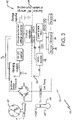
- the sensor unit 12 preferably is mounted in or on a tire 16 that supports a vehicle 18.
- the tire 16 includes a pair of bead areas 20 (only one shown) and a bead core (not shown) embedded in each bead area.
- Each one of a pair of sidewalls 22 (only one shown) extends radially outward from a respective bead area 20 to a ground-contacting tread 24.
- the tire 16 is reinforced by a carcass 26 that toroidally extends from one bead area 20 to the other bead area, as known to those skilled in the art.
- An innerliner 28 is formed on the inside surface of the carcass 26.
- the tire 16 is mounted on a wheel 30 in a manner known to those skilled in the art and, when mounted, forms an internal cavity 32 that is filled with a pressurized fluid, such as air.
- the sensor unit 12 may be attached to the innerliner 28 by means such as an adhesive and measures certain parameters or conditions of the tire 16, as will be described in greater detail below. It is to be understood that the sensor unit 12 may be attached in such a manner, or to other components of the tire 16, such as between layers of the carcass 26, on or in one of the sidewalls 22, on or in the tread 24, and/or a combination thereof. For the purpose of convenience, reference herein shall be made to mounting of the sensor unit 12 on the tire 16, with the understanding that such mounting includes all such attachment.
- the sensor unit 12 may be attached to the wheel 30 on which the tire 16 is mounted. It is also to be understood that the sensor unit 12 shown in Figure 1 is by way of example, and that the sensor may be of any size and/or shape.
- the sensor unit 12 may be a disc-shaped unit as shown or may be a particulate inclusion type of unit as described in greater detail in US-A-2019/0187027 .
- the sensor unit 12 includes an integrated circuit 34, at least one sensor 36 and an antenna 38 that are integrated with one another or otherwise electronically connected.
- the sensor unit 12 may include a modular construction to enable easy electronic connection of multiple sensors 36 or other components.
- the sensor unit 12 may include more than one integrated circuit 34.
- the sensor unit 12 preferably includes a module 40 for storing identification (ID) information for the tire 16.
- the tire ID information may include manufacturing information for the tire 16, such as: the tire type; tire model; size information, such as rim size, width, and outer diameter; manufacturing location; manufacturing date; a treadcap code that includes or correlates to a compound identification; and a mold code that includes or correlates to a tread structure identification.
- the tire ID information may also include a service history or other information to identify specific features and parameters of each tire 16, as well as mechanical characteristics of the tire, such as cornering parameters, spring rate, load-inflation relationship, and the like.
- the sensor unit 12 preferably is configured to receive a radio frequency (RF) power signal and/or to transmit an RF data signal using the antenna 38 and the integrated circuit 34.
- the RF signal is an ultra high frequency (UHF) signal in a range of from 300 MegaHertz (MHz) to 3 GigaHertz (GHz).
- UHF ultra high frequency
- the sensor unit 12 transmits data measured by the sensors 36 and the tire ID information in the module 40 to the remote receiver 14, as will be described in greater detail below.
- the sensor unit 12 preferably includes a wireless power receiver 42 that is integrated with or coupled to the integrated circuit 34, as will be described in greater detail below.
- the sensor unit 12 may include a non-rechargeable battery, rechargeable battery, supercapacitor and/or energy harvesting structure that is integrated with or coupled to the integrated circuit 34.
- Exemplary sensors 36 include tire pressure monitoring system (TPMS) sensors.
- TPMS tire pressure monitoring system
- the sensor unit 12 includes a temperature sensor 44 that is electronically connected to the integrated circuit 34 and may be integrated into the integrated circuit.
- the temperature sensor 44 measures the temperature within the tire 16 during its use on the vehicle 18.
- the sensor unit 12 preferably is disposed at a specific location in or on the tire 16 to detect a temperature of specific components of the tire and/or the temperature in the cavity 32.
- the temperature sensor 44 and the integrated circuit 34 may track a temperature versus time history at a specific location in or on the tire 16 in order to provide data to predict when tire replacement should occur.
- the sensor unit 12 may also include a pressure sensor 46 that is electronically connected to the integrated circuit 34, and may be integrated into the integrated circuit.
- the pressure sensor 46 measures the pressure in the cavity 32 of the tire 16 during its use on the vehicle 18.
- the use of the temperature sensor 44 and/or the pressure sensor 46 in the sensor unit 12 enables the data measured by each sensor to be communicated to control systems of the vehicle 18 and/or a user of the vehicle.
- the sensor unit 12 is a passive unit. More particularly, the sensor unit 12 remains powered off unit it is actuated by the reader 14, as will be described in greater detail below.
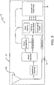
- An exemplary configuration of the integrated circuit 34 for the passive sensor unit 12 is shown in Figure 4 .
- the integrated circuit 34 preferably includes a printed circuit board 48, and the sensors 36 and the antenna 38 are electrically connected to the circuit board.
- An optional battery 50 as described above, may also be electrically connected to the printed circuit board 48.
- sensors 36 include accelerometers and similar acceleration-measuring sensors.
- the sensors 36 may include three-dimensional (3D) accelerometers, 3D gyroscopes and/or 3D magnetometer sensors.
- 3D sensors 36 measure the change of forces of the tire 16 and may be mounted on the innerliner 28 or the wheel 30. Data measured by such sensors 36 may be communicated from the sensor unit 12 to the receiver 14 and to a processor for use in determining tire load, traction coefficient and/or footprint length.
- Such properties may then be employed by control systems of the vehicle 18, such as vehicle stability control systems and traction control systems, to improve vehicle performance and safety.
- exemplary sensors 36 include strain or force indicators.
- a strain gauge may be disposed in or on the tread 24 or the sidewall 22. By measuring the strain in the tread 24, the sensor unit 12 may provide data indicating road conditions, and by measuring the strain in the sidewall 22, the sensor unit may provide data indicating the load on the tire 16. This data can be communicated to the vehicle stability and/or braking systems to provide improved control of the vehicle and can also be used for monitoring or tracking driving behavior.
- Exemplary strain gauges include flexible printed resistance-based strain gauges, piezoelectric-based strain/force gauges and electroactive polymer-based strain/force gauges.
- the sensor unit 12 may store or harvest energy from the piezoelectric or electroactive polymer in a capacitor. Such energy storage may enable the sensor unit 12 to activate and pro-actively contact the reader 14.
- the integrated circuit 34 preferably includes a converter 52. More particularly, the converter 52 is an analog-to-digital converter that receives an analog signal from any sensors 36 which output data in analog signal form and converts the signal into digital form for storage in the memory of the identification module 40 and/or transmission. When different types of sensors 36 are employed with a single reader 14, multiple converters 52 may be employed in the sensor unit 12.
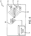
- the sensor unit 12 preferably is a passive RF component that is actuated by the external reader 14. More particularly, the sensor unit 12, including the integrated circuit 34 and the sensors 36, remain in a passive state.
- the reader 14 sends a predetermined wireless signal 54 through a reader antenna 56 to the sensor unit 12, the sensor unit antenna 38 ( Figure 2 ) receives the signal and actuates the integrated circuit 34.
- Each sensor 36 takes its respective measurements, and data from the sensor measurements is communicated to the integrated circuit 34. The data is stored on a memory unit of the integrated circuit 34 and transmitted wirelessly by the antenna 38 from the sensor unit 12 to the reader antenna 56 and the reader 14.
- the sensor unit 12 After the data is sent from the sensor unit 12 to the reader 14, the sensor unit preferably returns to its passive state. Each time that the reader 14 sends the signal 56 to the sensor unit 12, the sensor unit is actuated as described above. In this manner, multiple sensor measurements may be taken and stored without an ongoing power requirement by the sensor unit 12.
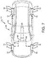
- the sensor unit 12 may include a micro-battery 50 or an energy harvester to extend the transmission range of the sensor unit and/or to periodically actuate the sensor unit to pro-actively contact the reader 14. As shown in Figure 6 , multiple sensor units 12 may be in communication with and actuated by a single reader 14. As will be described in greater detail below, the reader 14 may be mounted to the vehicle 18 for proximity with each sensor unit 12, such as on the vehicle body on a hub of the wheel 30.
- the reader 14 preferably employs ultra-high radio frequency transmission for the signal 54, as described above, with multiple communication protocols.
- the reader 14 may employ a Wi-Fi wireless communication protocol, an internet of things (loT) network protocol and/or a long-term evolution (LTE) communication protocol.
- LTE long-term evolution
- multiple sensors 36 of different types may transmit readable data from each sensor unit 12 to the reader 14 at a high reading rate, such as up to about fifty (50) to about seven hundred fifty (750) sensor units per second.
- each sensor unit 12 may be mounted on each tire 16, or on the respective wheel 30 on which each tire is mounted.
- each sensor unit 12 preferably is a passive RFID unit.
- a reader 14 is disposed proximate each tire 16 or wheel 30, and preferably is mounted on each tire or wheel. Each reader 14 communicates with the sensor units 12 that are disposed on the same tire 16 or wheel 30 as the reader. In this manner, each reader 14 is based upon a specific tire or wheel position and communicates with sensor units 12 at that position. The passive sensor units 12 at each tire or wheel position are actuated by their respective reader 14.
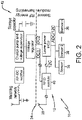
- a vehicle-mounted power unit 60 may be provided, which preferably is powered by the electrical system of the vehicle 18.
- the power unit 60 is selectively electrically connected to each reader 14, and preferably is a wireless power transmitter that employs an electromagnetic field or signal 62 to transfer a voltage to the readers.
- Each reader 14 includes a receiver that receives the signal 62 from the power unit 60, thereby enabling the power unit to wirelessly charge the readers.
- a central vehicle-mounted power unit 60 provides power to each reader 14, which in turn actuates each sensor unit 12.
- the first exemplary configuration 58 of the integrated tire sensor and reader system 10 enables the system to be installed on existing vehicles as a retrofit. More particularly, the single power unit 60 may easily be added to the vehicle 18, while the sensor units 12 and readers 14 are added to the tires 16 and/or wheels 30. In addition, the power unit 60 may be employed to charge other wireless electronics inside in proximity with the vehicle 18, such as a user's phone.
- each sensor unit 12 may be mounted on each tire 16, or on the respective wheel 30 on which each tire is mounted.
- each sensor unit 12 preferably is a passive RFID unit.
- a reader 14 is mounted to the vehicle 18 near each tire 16 or wheel 30. Each reader 14 communicates with the sensor units 12 that are disposed on the nearest tire 16 or wheel 30. In this manner, each reader 14 is based upon a specific tire or wheel position and communicates with sensor units 12 at that position. The passive sensor units 12 at each tire or wheel position are actuated by their respective reader 14. Each reader 14 may be powered by wires 66 which are connected to the electrical system of the vehicle 18 through a wired connection 68. In this manner, the electrical system of the vehicle 18 preferably provides hard-wired power to each reader 14, which in turn actuates each sensor unit 12.
- the second exemplary configuration 64 of the integrated tire sensor and reader system 10 enables the system to be installed on new vehicles in an economical manner.
- each sensor unit 12 may be mounted on each tire 16, or on the respective wheel 30 on which each tire is mounted.
- each sensor unit 12 preferably is a passive RFID unit.
- a single reader 14 is mounted to the vehicle 18 at a convenient central location.
- the reader 14 communicates with the sensor units 12 disposed on all of the tires 16 and/or wheels 30. In this manner, the reader 14 is a central reader that actuates all of the passive sensor units 12.
- the reader 14 may be powered by wires 72 which are connected to the electrical system of the vehicle 18 through a wired connection 74. In this manner, the electrical system of the vehicle 18 preferably provides hard-wired power to a single reader 14, which in turn actuates each sensor unit 12.
- the third exemplary configuration 70 of the integrated tire sensor and reader system 10 enables the system to be installed on new vehicles in an economical manner, and the use of a single reader 14 provides easier and thus improved data processing capability.
- the reader 14 may also be disposed on an infrastructure separate from the vehicle 18.
- the reader 14 may be installed on a horizontal surface over which the vehicle 18 is driven, or a vertical structure by which the vehicle passes, to actuate each sensor unit 12.
- Use of the reader 14 in a location that is separate from the vehicle 18 may be useful when large-scale reading of sensor units 12 is desired, such as at service locations and/or for fleets of vehicles.
- Such locations include an entrance to a fleet yard or lot, a parking garage, a gas station and/or a service station.
- the reader 14 may be disposed on an infrastructure such as a radio mast to actuate sensor units 12 within a pre-defined geographic area without the need to drive the vehicle 18 over or by a structure.
- Such geographic areas include limited geographic spaces for vehicles 18, such as a parking lot or deck, or a larger geographic region.
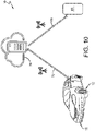
- the tire sensor and reader system 10 also includes communication of data to vehicle systems, a user of the vehicle 18 and/or to a central location for processing. More particularly, while each sensor unit 12 is passive and actuated by the reader 14, the reader is in electronic communication with the electronic control system of the vehicle 18. Thus, when the reader 14 receives data from the sensor units 12, the reader may transmit the data through the electronic control system of the vehicle 18 to specific vehicle control systems, such as the anti-lock braking system (ABS) and the electronic stability control system (ECS).
- ABS anti-lock braking system
- ECS electronic stability control system
- the data from the reader 14 may be wirelessly transmitted 76 from the vehicle to a remote server 78, such as a cloud-based server.
- the remote server 78 may enable collection and central review of measurements from the sensor units 12.
- selected data may be wirelessly transmitted 76 from the server 78 back to specific vehicle control systems, and/or may be wirelessly transmitted 80 to a device 82 for display that is accessible to a user of the vehicle 18, such as a smartphone.
- the tire sensor and reader system 10 of the present invention provides an integrated sensor and reader system that detects and communicates conditions in a tire during vehicle operation and withstands the harsh environment of a tire.
- the system 10 also communicates data accurately and repeatably in a cost-effective manner.
- the system 10 further includes a configuration that enables multiple sensors 12 to communicate with a reader 14, and which employs multiple standardized transmission or communication protocols.
- the system 10, and specifically the sensors 12, may be powered by means other than or in addition to a battery. Therefore, the tire sensor and reader system 10 of the present invention provides a simplified sensor-to-reader communication configuration that enables easy and dependable transfer of data from the sensors 12 to the reader 14 and to vehicle control systems, a central review location and/or a vehicle user.
- the present invention also includes a method of providing a tire sensor and reader system 10 on a vehicle 18.
- the method includes steps in accordance with the description that is presented above and shown in Figures 1 through 10 .
- the structure of the above-described the tire sensor and reader system 10 may be altered or rearranged, or components or steps known to those skilled in the art omitted or added, without affecting the overall concept or operation of the invention.
- the sensor units 12 may be disposed in any location in or on the tire 16 and/or the wheel 30, any number of sensor units and readers 14 may be employed, and other electronic structures may be connected to or integrated into the sensor unit and/or the reader.
Landscapes
- Engineering & Computer Science (AREA)
- Computer Networks & Wireless Communication (AREA)
- Mechanical Engineering (AREA)
- Arrangements For Transmission Of Measured Signals (AREA)
Claims (15)
- Integriertes Reifensensor- und Lesesystem, wobei das System (10) Folgendes umfasst:wenigstens eine Sensoreinheit (12), die an einem Reifen (16) und/oder einem Rad (30) montiert ist;einen Leser oder Empfänger (14), der von der wenigstens einen Sensoreinheit (12) entfernt angeordnet ist;wobei die wenigstens eine Sensoreinheit (12) wenigstens einen Sensor (36) zum Messen eines Parameters des Reifens (16) oder des Rades (30) und eine Antenne (38) zum Kommunizieren mit dem Leser oder dem Empfänger (14) beinhaltet, wobei die wenigstens eine Sensoreinheit (12) konfiguriert ist, um ein Funkfrequenzleistungssignal von dem Leser oder dem Empfänger (14) zu empfangen und Daten an den Leser oder den Empfänger (14) zu übertragen; undwobei der Leser oder der Empfänger (14) eine Antenne (56) zum Übertragen des Funkfrequenzleistungssignals an die wenigstens eine Sensoreinheit (12) beinhaltet, um die wenigstens eine Sensoreinheit (12) zu betätigen, wobei bei Betätigung der wenigstens einen Sensoreinheit (12), der wenigstens eine Sensor (36) den Parameter des Reifens (16) oder des Rades (30) misst, und Daten von dem wenigstens einen Sensor (36) von der wenigstens einen Sensoreinheit (12) an den Leser oder den Empfänger (14) übertragen werden; dadurch gekennzeichnet, dass der Leser oder der Empfänger (14) konfiguriert ist, um eine Ultrahochfunkfrequenzübertragung mit mehreren Kommunikationsprotokollen zu verwenden.
- Integriertes Reifensensor- und Lesesystem nach Anspruch 1, wobei das Funkfrequenzleistungssignal und das Kommunikationssignal zwischen dem Leser oder dem Empfänger (14) und der wenigstens einen Sensoreinheit (12) ein Ultrahochfrequenzsignal in einem Bereich von 300 Megahertz bis 3 Gigahertz ist.
- Integriertes Reifensensor- und Lesesystem nach Anspruch 1 oder 2, wobei die wenigstens eine Sensoreinheit (12) ein Modul (40) zum Speichern von Identifikationsinformationen für den Reifen (16) beinhaltet und die Identifikationsinformationen von der wenigstens einen Sensoreinheit (12) an den Leser oder den Empfänger (14) übertragen werden; und/oder wobei die wenigstens eine Sensoreinheit (12) ferner eine nicht wiederaufladbare Batterie (50), eine wiederaufladbare Batterie, einen Superkondensator und/oder eine Energiegewinnungsstruktur umfasst.
- Integriertes Reifensensor- und Lesesystem nach wenigstens einem der vorhergehenden Ansprüche, wobei der wenigstens eine Sensor (36) der wenigstens einen Sensoreinheit (12) einen Reifendrucküberwachungssystemsensor, einen Temperatursensor (44), einen Drucksensor (46), einen Laufflächenverschleißsensor, einen Beschleunigungsmesse, einen vorzugsweise leistungssparenden Ultraschallsensor und/oder einen Dehnungsanzeiger beinhaltet.
- Integriertes Reifensensor- und Lesesystem nach wenigstens einem der vorhergehenden Ansprüche, wobei die wenigstens eine Sensoreinheit (12) ferner einen Analog-DigitalWandler umfasst, um ein analoges Signal von dem wenigstens einen Sensor (36) zu empfangen und das Signal in digitale Form umzuwandeln.
- Integriertes Reifensensor- und Lesesystem nach wenigstens einem der vorhergehenden Ansprüche, wobei die Protokolle ein drahtloses Wi-Fi-Kommunikationsprotokoll, ein Internet der Dinge(internet of things - IoT)-Netzwerkprotokoll und/oder ein Long-Term-Evolution(LTE)-Kommunikationsprotokoll beinhalten.
- Integriertes Reifensensor- und Lesesystem nach wenigstens einem der vorhergehenden Ansprüche, wobei mehrere Sensoreinheiten (12) an dem Reifen (16) und/oder dem Rad (30) montiert sind.
- Integriertes Reifensensor- und Lesesystem nach wenigstens einem der vorhergehenden Ansprüche, wobei der Leser oder der Empfänger (14) an dem Reifen (16) oder dem Rad (30) montiert ist, an dem die wenigstens eine Sensoreinheit (12) montiert ist.
- Integriertes Reifensensor- und Lesesystem nach wenigstens einem der vorhergehenden Ansprüche, wobei der Leser oder der Empfänger (14) durch eine in einem Fahrzeug montierte Leistungseinheit mit Leistung versorgt wird, wobei die Leistungseinheit vorzugsweise eine Drahtlosleistungsübertragungseinrichtung beinhaltet.
- Integriertes Reifensensor- und Lesesystem nach wenigstens einem der vorhergehenden Ansprüche, wobei der Leser oder der Empfänger an einem Fahrzeug (18) montiert ist und/oder wobei der Leser oder der Empfänger (14) durch Drähte mit Leistung versorgt wird, die mit dem elektrischen System des Fahrzeugs (18) verbunden sind.
- Integriertes Reifensensor- und Lesesystem nach wenigstens einem der vorhergehenden Ansprüche, wobei der Leser oder der Empfänger in der Nähe des Reifens (16) oder des Rades (30) montiert ist, an dem die wenigstens eine Sensoreinheit (12) montiert ist, und/oder wobei der Leser oder der Empfänger (14) an einer zentralen Stelle montiert ist.
- Integriertes Reifensensor- und Lesesystem nach wenigstens einem der vorhergehenden Ansprüche, wobei der Leser oder der Empfänger (14) auf einer von dem Fahrzeug (18) getrennten Infrastruktur angeordnet ist.
- Integriertes Reifensensor- und Lesesystem nach wenigstens einem der vorhergehenden Ansprüche, wobei:die wenigstens eine Sensoreinheit (12) eine erste Sensoreinheit ist, die an einem ersten von einem Reifen (16) und/oder einem Rad (30) montiert ist;eine zweite Sensoreinheit an einem zweiten von einem Reifen (16) und/oder einem Rad (30) montiert ist;der Leser oder der Empfänger (14) ein erster Leser ist und mit der ersten Sensoreinheit (12) in Kommunikation steht; undein zweiter Leser oder Empfänger mit der zweiten Sensoreinheit in Kommunikation steht.
- Integriertes Reifensensor- und Lesesystem nach wenigstens einem der vorhergehenden Ansprüche, wobei der Leser oder der Empfänger (14) konfiguriert ist, um Daten von der wenigstens einen Sensoreinheit (12) an ein elektronisches Steuersystem eines Fahrzeugs (18) und/oder einen entfernten Server (78) zu übertragen und/oder wobei das System konfiguriert ist, um Daten an eine Anzeigevorrichtung zu übertragen, die für einen Benutzer des Fahrzeugs (18) zugänglich ist.
- Verfahren zum Betreiben eines Reifensensor- und Lesesystems (10) an einem Fahrzeug (18), wobei das Verfahren Folgendes umfasst:Bereitstellen wenigstens einer Sensoreinheit (12), die an einem Reifen (16) und/oder einem Rad (30) montiert ist;Bereitstellen eines Lesers oder Empfängers (14), der von der wenigstens einen Sensoreinheit (12) entfernt angeordnet ist;wobei die wenigstens eine Sensoreinheit (12) wenigstens einen Sensor (36), der einen Parameter des Reifens (16) oder des Rades (30) misst, und eine Antenne (38) beinhaltet, die mit dem Leser oder dem Empfänger (14) kommuniziert,wobei die wenigstens eine Sensoreinheit (12) ein Funkfrequenzleistungssignal von dem Leser oder dem Empfänger (14) empfängt und Daten an den Leser oder den Empfänger (14) überträgt;wobei der Leser oder der Empfänger (14) eine Antenne (56) beinhaltet, die das Funkfrequenzleistungssignal an die wenigstens eine Sensoreinheit (12) überträgt, um die wenigstens eine Sensoreinheit (12) zu betätigen, undwobei bei Betätigung der wenigstens einen Sensoreinheit (12) der wenigstens eine Sensor (36) den Parameter des Reifens (16) oder des Rades (30) misst und Daten von dem wenigstens einen Sensor (36) von der wenigstens einen Sensoreinheit (12) an den Leser oder den Empfänger (14) übertragen werden; dadurch gekennzeichnet, dassder Leser oder der Empfänger (14) eine Ultrahochfunkfrequenzübertragung mit mehreren Kommunikationsprotokollen verwendet.
Applications Claiming Priority (1)
| Application Number | Priority Date | Filing Date | Title |
|---|---|---|---|
| US16/210,069 US10935466B2 (en) | 2017-12-20 | 2018-12-05 | Integrated tire sensor and reader system |
Publications (2)
| Publication Number | Publication Date |
|---|---|
| EP3663110A1 EP3663110A1 (de) | 2020-06-10 |
| EP3663110B1 true EP3663110B1 (de) | 2022-07-20 |
Family
ID=68771533
Family Applications (1)
| Application Number | Title | Priority Date | Filing Date |
|---|---|---|---|
| EP19213579.6A Active EP3663110B1 (de) | 2018-12-05 | 2019-12-04 | Integriertes reifensensor- und -lesesystem |
Country Status (1)
| Country | Link |
|---|---|
| EP (1) | EP3663110B1 (de) |
Family Cites Families (5)
| Publication number | Priority date | Publication date | Assignee | Title |
|---|---|---|---|---|
| FR2817509B1 (fr) * | 2000-12-05 | 2003-08-29 | Trw France | Systeme de mesure de parametres de roue et detecteur de mesure pour un tel systeme |
| JP3971918B2 (ja) * | 2001-11-28 | 2007-09-05 | 株式会社ブリヂストン | タイヤ内圧センサユニット、リム組立体、タイヤ、および、タイヤ管理システム |
| KR101713238B1 (ko) * | 2016-05-16 | 2017-03-07 | 넥센타이어 주식회사 | 타이어 모니터링 장치 및 이를 구비한 차량 |
| US10935466B2 (en) | 2017-12-20 | 2021-03-02 | The Goodyear Tire & Rubber Company | Integrated tire sensor and reader system |
| US10792960B2 (en) * | 2017-12-20 | 2020-10-06 | The Goodyear Tire & Rubber Company | Article with electronic component inclusion |
-
2019
- 2019-12-04 EP EP19213579.6A patent/EP3663110B1/de active Active
Also Published As
| Publication number | Publication date |
|---|---|
| EP3663110A1 (de) | 2020-06-10 |
Similar Documents
| Publication | Publication Date | Title |
|---|---|---|
| US10935466B2 (en) | Integrated tire sensor and reader system | |
| EP3838631B1 (de) | Flexible reifensensoreinheit und reifen | |
| EP3505336B1 (de) | Artikel mit elektronischer komponentenaufnahme und verfahren zur herstellung | |
| CN112440628B (zh) | 利用印迹长度的轮胎磨损估计系统和方法 | |
| US5749984A (en) | Tire monitoring system and method | |
| US7021132B2 (en) | Measuring system for wheel parameters and measuring detector for such a system | |
| US9649889B2 (en) | Autonomous, plug-in wear or abrasion sensing system | |
| EP1487682B1 (de) | Reifenüberwachungssystem und -vorrichtung eines kraftfahrzeugs | |
| EP2018980B1 (de) | Reifenlokalisierungssystem | |
| EP3501855B1 (de) | Sensorsystem zur überwachung des reifenverschleisses | |
| EP3838632B1 (de) | Gekapselte eingebettete reifensensoreinheit | |
| EP4015255B1 (de) | Reifen mit polymerstecker für laufflächenabnutzungserfassung und verfahren zur herstellung | |
| US11273801B2 (en) | Control system for an air maintenance tire system | |
| US20210016614A1 (en) | Tire with an integrated rfid and tpms sensor | |
| EP4015252B1 (de) | Fahrzeugreifensensorhaltesystem | |
| EP4101659B1 (de) | System und verfahren zur reifenwechselvorhersage | |
| EP3663110B1 (de) | Integriertes reifensensor- und -lesesystem | |
| EP1572474A1 (de) | Umdrehungszähler für einen reifen | |
| US20260044693A1 (en) | Method for reading information contained in an rfid chip embedded in a vehicle tire | |
| US20240416690A1 (en) | Sensor data retrieval from radio frequency identification (rfid) device | |
| CN101400528B (zh) | 包括至少一个被安装组件的车辆以及测量系统的使用 |
Legal Events
| Date | Code | Title | Description |
|---|---|---|---|
| PUAI | Public reference made under article 153(3) epc to a published international application that has entered the european phase |
Free format text: ORIGINAL CODE: 0009012 |
|
| STAA | Information on the status of an ep patent application or granted ep patent |
Free format text: STATUS: THE APPLICATION HAS BEEN PUBLISHED |
|
| AK | Designated contracting states |
Kind code of ref document: A1 Designated state(s): AL AT BE BG CH CY CZ DE DK EE ES FI FR GB GR HR HU IE IS IT LI LT LU LV MC MK MT NL NO PL PT RO RS SE SI SK SM TR |
|
| AX | Request for extension of the european patent |
Extension state: BA ME |
|
| RIN1 | Information on inventor provided before grant (corrected) |
Inventor name: LIN, CHENG-HSIUNG Inventor name: SUH, PETER JUNG-MIN Inventor name: PULFORD, CARL TREVOR ROSS |
|
| STAA | Information on the status of an ep patent application or granted ep patent |
Free format text: STATUS: REQUEST FOR EXAMINATION WAS MADE |
|
| 17P | Request for examination filed |
Effective date: 20201210 |
|
| RBV | Designated contracting states (corrected) |
Designated state(s): AL AT BE BG CH CY CZ DE DK EE ES FI FR GB GR HR HU IE IS IT LI LT LU LV MC MK MT NL NO PL PT RO RS SE SI SK SM TR |
|
| RIC1 | Information provided on ipc code assigned before grant |
Ipc: B60C 23/04 20060101AFI20211215BHEP |
|
| GRAP | Despatch of communication of intention to grant a patent |
Free format text: ORIGINAL CODE: EPIDOSNIGR1 |
|
| STAA | Information on the status of an ep patent application or granted ep patent |
Free format text: STATUS: GRANT OF PATENT IS INTENDED |
|
| INTG | Intention to grant announced |
Effective date: 20220201 |
|
| GRAS | Grant fee paid |
Free format text: ORIGINAL CODE: EPIDOSNIGR3 |
|
| GRAA | (expected) grant |
Free format text: ORIGINAL CODE: 0009210 |
|
| STAA | Information on the status of an ep patent application or granted ep patent |
Free format text: STATUS: THE PATENT HAS BEEN GRANTED |
|
| AK | Designated contracting states |
Kind code of ref document: B1 Designated state(s): AL AT BE BG CH CY CZ DE DK EE ES FI FR GB GR HR HU IE IS IT LI LT LU LV MC MK MT NL NO PL PT RO RS SE SI SK SM TR |
|
| REG | Reference to a national code |
Ref country code: CH Ref legal event code: EP |
|
| REG | Reference to a national code |
Ref country code: DE Ref legal event code: R096 Ref document number: 602019017170 Country of ref document: DE |
|
| REG | Reference to a national code |
Ref country code: AT Ref legal event code: REF Ref document number: 1505310 Country of ref document: AT Kind code of ref document: T Effective date: 20220815 |
|
| REG | Reference to a national code |
Ref country code: IE Ref legal event code: FG4D |
|
| REG | Reference to a national code |
Ref country code: LT Ref legal event code: MG9D |
|
| REG | Reference to a national code |
Ref country code: NL Ref legal event code: MP Effective date: 20220720 |
|
| PG25 | Lapsed in a contracting state [announced via postgrant information from national office to epo] |
Ref country code: SE Free format text: LAPSE BECAUSE OF FAILURE TO SUBMIT A TRANSLATION OF THE DESCRIPTION OR TO PAY THE FEE WITHIN THE PRESCRIBED TIME-LIMIT Effective date: 20220720 Ref country code: RS Free format text: LAPSE BECAUSE OF FAILURE TO SUBMIT A TRANSLATION OF THE DESCRIPTION OR TO PAY THE FEE WITHIN THE PRESCRIBED TIME-LIMIT Effective date: 20220720 Ref country code: PT Free format text: LAPSE BECAUSE OF FAILURE TO SUBMIT A TRANSLATION OF THE DESCRIPTION OR TO PAY THE FEE WITHIN THE PRESCRIBED TIME-LIMIT Effective date: 20221121 Ref country code: NO Free format text: LAPSE BECAUSE OF FAILURE TO SUBMIT A TRANSLATION OF THE DESCRIPTION OR TO PAY THE FEE WITHIN THE PRESCRIBED TIME-LIMIT Effective date: 20221020 Ref country code: NL Free format text: LAPSE BECAUSE OF FAILURE TO SUBMIT A TRANSLATION OF THE DESCRIPTION OR TO PAY THE FEE WITHIN THE PRESCRIBED TIME-LIMIT Effective date: 20220720 Ref country code: LV Free format text: LAPSE BECAUSE OF FAILURE TO SUBMIT A TRANSLATION OF THE DESCRIPTION OR TO PAY THE FEE WITHIN THE PRESCRIBED TIME-LIMIT Effective date: 20220720 Ref country code: LT Free format text: LAPSE BECAUSE OF FAILURE TO SUBMIT A TRANSLATION OF THE DESCRIPTION OR TO PAY THE FEE WITHIN THE PRESCRIBED TIME-LIMIT Effective date: 20220720 Ref country code: FI Free format text: LAPSE BECAUSE OF FAILURE TO SUBMIT A TRANSLATION OF THE DESCRIPTION OR TO PAY THE FEE WITHIN THE PRESCRIBED TIME-LIMIT Effective date: 20220720 Ref country code: ES Free format text: LAPSE BECAUSE OF FAILURE TO SUBMIT A TRANSLATION OF THE DESCRIPTION OR TO PAY THE FEE WITHIN THE PRESCRIBED TIME-LIMIT Effective date: 20220720 |
|
| REG | Reference to a national code |
Ref country code: AT Ref legal event code: MK05 Ref document number: 1505310 Country of ref document: AT Kind code of ref document: T Effective date: 20220720 |
|
| PG25 | Lapsed in a contracting state [announced via postgrant information from national office to epo] |
Ref country code: PL Free format text: LAPSE BECAUSE OF FAILURE TO SUBMIT A TRANSLATION OF THE DESCRIPTION OR TO PAY THE FEE WITHIN THE PRESCRIBED TIME-LIMIT Effective date: 20220720 Ref country code: IS Free format text: LAPSE BECAUSE OF FAILURE TO SUBMIT A TRANSLATION OF THE DESCRIPTION OR TO PAY THE FEE WITHIN THE PRESCRIBED TIME-LIMIT Effective date: 20221120 Ref country code: HR Free format text: LAPSE BECAUSE OF FAILURE TO SUBMIT A TRANSLATION OF THE DESCRIPTION OR TO PAY THE FEE WITHIN THE PRESCRIBED TIME-LIMIT Effective date: 20220720 Ref country code: GR Free format text: LAPSE BECAUSE OF FAILURE TO SUBMIT A TRANSLATION OF THE DESCRIPTION OR TO PAY THE FEE WITHIN THE PRESCRIBED TIME-LIMIT Effective date: 20221021 |
|
| REG | Reference to a national code |
Ref country code: DE Ref legal event code: R097 Ref document number: 602019017170 Country of ref document: DE |
|
| PG25 | Lapsed in a contracting state [announced via postgrant information from national office to epo] |
Ref country code: SM Free format text: LAPSE BECAUSE OF FAILURE TO SUBMIT A TRANSLATION OF THE DESCRIPTION OR TO PAY THE FEE WITHIN THE PRESCRIBED TIME-LIMIT Effective date: 20220720 Ref country code: RO Free format text: LAPSE BECAUSE OF FAILURE TO SUBMIT A TRANSLATION OF THE DESCRIPTION OR TO PAY THE FEE WITHIN THE PRESCRIBED TIME-LIMIT Effective date: 20220720 Ref country code: DK Free format text: LAPSE BECAUSE OF FAILURE TO SUBMIT A TRANSLATION OF THE DESCRIPTION OR TO PAY THE FEE WITHIN THE PRESCRIBED TIME-LIMIT Effective date: 20220720 Ref country code: CZ Free format text: LAPSE BECAUSE OF FAILURE TO SUBMIT A TRANSLATION OF THE DESCRIPTION OR TO PAY THE FEE WITHIN THE PRESCRIBED TIME-LIMIT Effective date: 20220720 Ref country code: AT Free format text: LAPSE BECAUSE OF FAILURE TO SUBMIT A TRANSLATION OF THE DESCRIPTION OR TO PAY THE FEE WITHIN THE PRESCRIBED TIME-LIMIT Effective date: 20220720 |
|
| PLBE | No opposition filed within time limit |
Free format text: ORIGINAL CODE: 0009261 |
|
| STAA | Information on the status of an ep patent application or granted ep patent |
Free format text: STATUS: NO OPPOSITION FILED WITHIN TIME LIMIT |
|
| PG25 | Lapsed in a contracting state [announced via postgrant information from national office to epo] |
Ref country code: SK Free format text: LAPSE BECAUSE OF FAILURE TO SUBMIT A TRANSLATION OF THE DESCRIPTION OR TO PAY THE FEE WITHIN THE PRESCRIBED TIME-LIMIT Effective date: 20220720 Ref country code: EE Free format text: LAPSE BECAUSE OF FAILURE TO SUBMIT A TRANSLATION OF THE DESCRIPTION OR TO PAY THE FEE WITHIN THE PRESCRIBED TIME-LIMIT Effective date: 20220720 |
|
| 26N | No opposition filed |
Effective date: 20230421 |
|
| PG25 | Lapsed in a contracting state [announced via postgrant information from national office to epo] |
Ref country code: AL Free format text: LAPSE BECAUSE OF FAILURE TO SUBMIT A TRANSLATION OF THE DESCRIPTION OR TO PAY THE FEE WITHIN THE PRESCRIBED TIME-LIMIT Effective date: 20220720 |
|
| REG | Reference to a national code |
Ref country code: CH Ref legal event code: PL |
|
| REG | Reference to a national code |
Ref country code: BE Ref legal event code: MM Effective date: 20221231 |
|
| PG25 | Lapsed in a contracting state [announced via postgrant information from national office to epo] |
Ref country code: SI Free format text: LAPSE BECAUSE OF FAILURE TO SUBMIT A TRANSLATION OF THE DESCRIPTION OR TO PAY THE FEE WITHIN THE PRESCRIBED TIME-LIMIT Effective date: 20220720 Ref country code: LU Free format text: LAPSE BECAUSE OF NON-PAYMENT OF DUE FEES Effective date: 20221204 |
|
| PG25 | Lapsed in a contracting state [announced via postgrant information from national office to epo] |
Ref country code: LI Free format text: LAPSE BECAUSE OF NON-PAYMENT OF DUE FEES Effective date: 20221231 Ref country code: IE Free format text: LAPSE BECAUSE OF NON-PAYMENT OF DUE FEES Effective date: 20221204 Ref country code: CH Free format text: LAPSE BECAUSE OF NON-PAYMENT OF DUE FEES Effective date: 20221231 |
|
| PG25 | Lapsed in a contracting state [announced via postgrant information from national office to epo] |
Ref country code: BE Free format text: LAPSE BECAUSE OF NON-PAYMENT OF DUE FEES Effective date: 20221231 |
|
| PGFP | Annual fee paid to national office [announced via postgrant information from national office to epo] |
Ref country code: GB Payment date: 20231012 Year of fee payment: 5 |
|
| PG25 | Lapsed in a contracting state [announced via postgrant information from national office to epo] |
Ref country code: HU Free format text: LAPSE BECAUSE OF FAILURE TO SUBMIT A TRANSLATION OF THE DESCRIPTION OR TO PAY THE FEE WITHIN THE PRESCRIBED TIME-LIMIT; INVALID AB INITIO Effective date: 20191204 |
|
| PG25 | Lapsed in a contracting state [announced via postgrant information from national office to epo] |
Ref country code: CY Free format text: LAPSE BECAUSE OF FAILURE TO SUBMIT A TRANSLATION OF THE DESCRIPTION OR TO PAY THE FEE WITHIN THE PRESCRIBED TIME-LIMIT Effective date: 20220720 |
|
| PG25 | Lapsed in a contracting state [announced via postgrant information from national office to epo] |
Ref country code: MK Free format text: LAPSE BECAUSE OF FAILURE TO SUBMIT A TRANSLATION OF THE DESCRIPTION OR TO PAY THE FEE WITHIN THE PRESCRIBED TIME-LIMIT Effective date: 20220720 |
|
| PG25 | Lapsed in a contracting state [announced via postgrant information from national office to epo] |
Ref country code: MC Free format text: LAPSE BECAUSE OF FAILURE TO SUBMIT A TRANSLATION OF THE DESCRIPTION OR TO PAY THE FEE WITHIN THE PRESCRIBED TIME-LIMIT Effective date: 20220720 |
|
| PG25 | Lapsed in a contracting state [announced via postgrant information from national office to epo] |
Ref country code: TR Free format text: LAPSE BECAUSE OF FAILURE TO SUBMIT A TRANSLATION OF THE DESCRIPTION OR TO PAY THE FEE WITHIN THE PRESCRIBED TIME-LIMIT Effective date: 20220720 Ref country code: MC Free format text: LAPSE BECAUSE OF FAILURE TO SUBMIT A TRANSLATION OF THE DESCRIPTION OR TO PAY THE FEE WITHIN THE PRESCRIBED TIME-LIMIT Effective date: 20220720 |
|
| PG25 | Lapsed in a contracting state [announced via postgrant information from national office to epo] |
Ref country code: BG Free format text: LAPSE BECAUSE OF FAILURE TO SUBMIT A TRANSLATION OF THE DESCRIPTION OR TO PAY THE FEE WITHIN THE PRESCRIBED TIME-LIMIT Effective date: 20220720 |
|
| PG25 | Lapsed in a contracting state [announced via postgrant information from national office to epo] |
Ref country code: MT Free format text: LAPSE BECAUSE OF FAILURE TO SUBMIT A TRANSLATION OF THE DESCRIPTION OR TO PAY THE FEE WITHIN THE PRESCRIBED TIME-LIMIT Effective date: 20220720 |
|
| GBPC | Gb: european patent ceased through non-payment of renewal fee |
Effective date: 20241204 |
|
| PG25 | Lapsed in a contracting state [announced via postgrant information from national office to epo] |
Ref country code: GB Free format text: LAPSE BECAUSE OF NON-PAYMENT OF DUE FEES Effective date: 20241204 |
|
| PGFP | Annual fee paid to national office [announced via postgrant information from national office to epo] |
Ref country code: DE Payment date: 20251126 Year of fee payment: 7 |
|
| PGFP | Annual fee paid to national office [announced via postgrant information from national office to epo] |
Ref country code: IT Payment date: 20251119 Year of fee payment: 7 |
|
| PGFP | Annual fee paid to national office [announced via postgrant information from national office to epo] |
Ref country code: FR Payment date: 20251120 Year of fee payment: 7 |