EP3663233A1 - Système d'évacuation de fluide et dispositif de pression et de poussée associé - Google Patents
Système d'évacuation de fluide et dispositif de pression et de poussée associé Download PDFInfo
- Publication number
- EP3663233A1 EP3663233A1 EP18841657.2A EP18841657A EP3663233A1 EP 3663233 A1 EP3663233 A1 EP 3663233A1 EP 18841657 A EP18841657 A EP 18841657A EP 3663233 A1 EP3663233 A1 EP 3663233A1
- Authority
- EP
- European Patent Office
- Prior art keywords
- squeezing
- base
- shaft
- squeezer
- rolling
- Prior art date
- Legal status (The legal status is an assumption and is not a legal conclusion. Google has not performed a legal analysis and makes no representation as to the accuracy of the status listed.)
- Granted
Links
Images




Classifications
-
- B—PERFORMING OPERATIONS; TRANSPORTING
- B65—CONVEYING; PACKING; STORING; HANDLING THIN OR FILAMENTARY MATERIAL
- B65D—CONTAINERS FOR STORAGE OR TRANSPORT OF ARTICLES OR MATERIALS, e.g. BAGS, BARRELS, BOTTLES, BOXES, CANS, CARTONS, CRATES, DRUMS, JARS, TANKS, HOPPERS, FORWARDING CONTAINERS; ACCESSORIES, CLOSURES, OR FITTINGS THEREFOR; PACKAGING ELEMENTS; PACKAGES
- B65D88/00—Large containers
- B65D88/54—Large containers characterised by means facilitating filling or emptying
-
- B—PERFORMING OPERATIONS; TRANSPORTING
- B65—CONVEYING; PACKING; STORING; HANDLING THIN OR FILAMENTARY MATERIAL
- B65D—CONTAINERS FOR STORAGE OR TRANSPORT OF ARTICLES OR MATERIALS, e.g. BAGS, BARRELS, BOTTLES, BOXES, CANS, CARTONS, CRATES, DRUMS, JARS, TANKS, HOPPERS, FORWARDING CONTAINERS; ACCESSORIES, CLOSURES, OR FITTINGS THEREFOR; PACKAGING ELEMENTS; PACKAGES
- B65D77/00—Packages formed by enclosing articles or materials in preformed containers, e.g. boxes, cartons, sacks or bags
- B65D77/04—Articles or materials enclosed in two or more containers disposed one within another
- B65D77/06—Liquids or semi-liquids or other materials or articles enclosed in flexible containers disposed within rigid containers
- B65D77/062—Flexible containers disposed within polygonal containers formed by folding a carton blank
- B65D77/065—Spouts, pouring necks or discharging tubes fixed to or integral with the flexible container
-
- B—PERFORMING OPERATIONS; TRANSPORTING
- B65—CONVEYING; PACKING; STORING; HANDLING THIN OR FILAMENTARY MATERIAL
- B65D—CONTAINERS FOR STORAGE OR TRANSPORT OF ARTICLES OR MATERIALS, e.g. BAGS, BARRELS, BOTTLES, BOXES, CANS, CARTONS, CRATES, DRUMS, JARS, TANKS, HOPPERS, FORWARDING CONTAINERS; ACCESSORIES, CLOSURES, OR FITTINGS THEREFOR; PACKAGING ELEMENTS; PACKAGES
- B65D90/00—Component parts, details or accessories for large containers
-
- B—PERFORMING OPERATIONS; TRANSPORTING
- B67—OPENING, CLOSING OR CLEANING BOTTLES, JARS OR SIMILAR CONTAINERS; LIQUID HANDLING
- B67D—DISPENSING, DELIVERING OR TRANSFERRING LIQUIDS, NOT OTHERWISE PROVIDED FOR
- B67D7/00—Apparatus or devices for transferring liquids from bulk storage containers or reservoirs into vehicles or into portable containers, e.g. for retail sale purposes
- B67D7/02—Apparatus or devices for transferring liquids from bulk storage containers or reservoirs into vehicles or into portable containers, e.g. for retail sale purposes for transferring liquids other than fuel or lubricants
- B67D7/0216—Apparatus or devices for transferring liquids from bulk storage containers or reservoirs into vehicles or into portable containers, e.g. for retail sale purposes for transferring liquids other than fuel or lubricants by squeezing collapsible or flexible storage containers
-
- B—PERFORMING OPERATIONS; TRANSPORTING
- B65—CONVEYING; PACKING; STORING; HANDLING THIN OR FILAMENTARY MATERIAL
- B65D—CONTAINERS FOR STORAGE OR TRANSPORT OF ARTICLES OR MATERIALS, e.g. BAGS, BARRELS, BOTTLES, BOXES, CANS, CARTONS, CRATES, DRUMS, JARS, TANKS, HOPPERS, FORWARDING CONTAINERS; ACCESSORIES, CLOSURES, OR FITTINGS THEREFOR; PACKAGING ELEMENTS; PACKAGES
- B65D2590/00—Component parts, details or accessories for large containers
- B65D2590/02—Wall construction
- B65D2590/04—Linings
- B65D2590/043—Flexible liners
- B65D2590/046—Bladders
-
- B—PERFORMING OPERATIONS; TRANSPORTING
- B67—OPENING, CLOSING OR CLEANING BOTTLES, JARS OR SIMILAR CONTAINERS; LIQUID HANDLING
- B67D—DISPENSING, DELIVERING OR TRANSFERRING LIQUIDS, NOT OTHERWISE PROVIDED FOR
- B67D2210/00—Indexing scheme relating to aspects and details of apparatus or devices for dispensing beverages on draught or for controlling flow of liquids under gravity from storage containers for dispensing purposes
- B67D2210/0016—Adapted for dispensing high viscosity products
Definitions
- This invention relates to logistics transportation field, and in particular a transportation and discharge system for fluid, especially viscous liquid.
- US5765723A disclosed a sealed liquid bag, the body thereof is a sealed soft container made by hot-melting welding or high-frequency welding PVC plastic-coated cloth; the sealed soft container is provided with an inlet valve and an outlet valve at two ends thereof.
- This liquid liner bag body is effective when using in the high speed low viscous liquid; however, during viscous liquid discharging, the discharge is inefficient; there are much liquid residues in the bag after discharging, rendering waste of liquid.
- the liner bag is twisted by spirally twisting and squeezing the body thereof to squeeze the liquid residues out.
- IL156984A disclosed a sealed liquid bag, the body thereof is a sealed soft container made by hot-melting welding or high-frequency welding PVC plastic-coated cloth or PE film; the sealed soft container is provided with an inlet valve and an outlet valve at two ends thereof; the body also includes a gas bag for assisting in discharging, with an gas charging port on the gas bag.
- the assisted gas bag need to be charged with gas, the viscous liquid is discharged by the squeezing of the gas. This solution cannot solve the problem of liquid residues completely, and assisted gas charging is needed, rendering the increase of cost.
- US2015284181A1 disclosed a sealed liquid bag, the body thereof is a sealed soft container made by hot-melting welding or high-frequency welding PVC plastic-coated cloth or PE film; when viscous liquid discharging, the intermediate bulk container for transporting liquid is tilted by mechanical structure so that the discharging outlet is located at the lowest position.
- Such an operation is time consuming, inefficient, and inconvenient, further there are much liquid residues in the liner bag after discharging, rendering waste of liquid.
- WO2011080402A1 discloses a liquid squeezing device for squeezing viscous liquid.
- the sealed liquid bag has to be hanged before squeezing, then with the squeezing of the hanged liquid bag, the hanged liquid bag is pulled upwardly.
- These squeezing device is costly and bulky, and the operation is complicated, time-consuming, inefficient and difficult.
- the invention aims to provide a simple, compact, cost-effective, operation friendly, and durable squeezer with little liquid residue in the squeezed liner bag.
- a squeezer comprising a pair of rolling shafts, a driving device and a mounting bracket, wherein the pair of rolling shafts being rotatably mounted to the mounting bracket, each rolling shaft having a mounting part at each end and a squeezing segment located between the mounting parts; the squeezing segment including a supporting shaft and an elastic body surrounding the supporting shaft; the pair of rollers being capable of operatively clamping an object to be clamped between the squeezing segments and oppositely being rotated by the driving device to apply a squeezing force to the object clamped, and the squeezer further comprising a protective device for protecting the elastic body at ends of the squeezing segment.
- the protective device is a protective part provided on the mounting bracket, and both ends of the squeezing segment are received in the protective part of the mounting bracket.
- the mounting bracket comprises a first base and a second base respectively arranged at both ends of the rolling shaft, wherein both the first base and the second base are provided with concave recesses, and both ends of the squeezing segment are respectively received in the recesses of the first base and the second base.
- the squeezing segment of one of the pair of rolling shafts received in the recess of the first base and the squeezing segment of the other received in the recess of first base are not in contact with each other; and the squeezing segment of one of the pair of rolling shafts received in the recess of the second base and the squeezing segment of the other received in the recess of the second base are not in contact with each other.
- each of the two ends of the squeezing segment is received in the protective part by a length of 25mm-60mm; or, each of both ends of the squeezing segment is received in the protective part by a length of 1/20 to 1/16 of the total length of the squeezing segment.
- the mounting bracket comprises two first bases, two supporting rods, a second base and a locking mechanism; two ends of each of the two supporting rods are connected to the first base and the second base respectively; one end of the rolling shaft is rotatably mounted to the first base, the other end is rotatably mounted to the second base, and the locking mechanism is used to operatively lock or release the pair of rolling shafts.
- the locking mechanism includes a locking spanner and lateral threaded holes provided on two first bases, wherein the lateral threaded hole on one of the first bases is a through hole and the lateral threaded hole on the other is a through hole or a blind hole, and the locking spanner is screwed through the through threaded hole on one of the first bases into another threaded hole to operatively lock the pair of rollers.
- the protective device is a concave-convex structure provided on an outer surface of the supporting shaft and an inner surface of the elastic body.
- the protective device is a protective structure for preventing from rotating relative to each other, and the protective structure is provided at a position on the supporting shaft of the squeezing segment corresponding to the end of the elastic body.
- the protective structure comprises a plurality of axially extending grooves in a supporting shaft in the squeezing segment; and opposite flanges are provided at the opening of each of the grooves.
- the driving device is arranged at an end of the rolling shaft, wherein the driving device comprises a motor and a reducer, wherein an output shaft of the reducer and the mounting part of the rolling shaft are connected with each other, and the motor is located above the rolling shaft.
- the output shaft of the motor is perpendicular to the rolling shaft; or the output shaft of the motor is parallel to the rolling shaft.
- the cross section of the roller is circular or oval.
- an outer diameter of at least a part of the elastic body is uniformly changed in the axial direction, thereby forming an elastic body having a taper.
- the object to be clamped is a liner bag for containing liquid
- the pair of rollers are arranged to be capable of descending as the liquid in the inner liner bag is lowered while rotating relatively in the opposite direction.
- the cross section of the roller is circular or oval.
- a squeezer comprising : a pair of rolling shafts, a driving device and a mounting bracket, wherein the pair of rolling shafts being rotatably mounted to the mounting bracket, each rolling shaft having a mounting part at each end and a squeezing segment located between the mounting parts; the squeezing segment including a supporting shaft and an elastic body surrounding the supporting shaft; the pair of rollers being capable of operatively clamping an object to be clamped between the squeezing segments and oppositely being rotated by the driving device to apply a squeezing force to the object clamped, and the squeezer further comprising a protective device for protecting the elastic body at ends of the squeezing segment and a guarding device provided to surround at least the outer side of the rolling shaft so that during the squeezing process of the squeezer, the outer side of the rolling shaft is separated from the object clamped.
- the guarding device is formed by supporting rods of the mounting bracket, wherein the cross-sectional shape of the supporting rod is U-shaped or C-shaped.
- a fluid discharge system comprising a container and a liner bag, said liner bag being provided with a discharge port and installed in the container, wherein the fluid discharge system further comprises the squeezer mentioned above, wherein the pair of rolling shafts operatively clamp the liner bag between the squeezing segments and are able to oppositely rotated by the driving device to apply a squeezing force to the liner bag.
- the fluid discharge system provided by this invention is a zero-residue discharge system needing not to hanging the liner bag, and has a simple structure, a good manufacturing process, simple operation, and cost savings.
- IBC container composite intermediate bulk container
- IBC container barrels can be reused many times, they have obvious advantages in filling, storage, and transportation, and compared to cylindrical barrels, IBC container barrels can save 35% of storage space, the dimensions accord with ISO standards, and not only applicable to sterile filling but also compact, convenient for safe and efficient storage in large scale, so it is widely used in the transportation, packaging, and storage of liquids, particles, and flakes etc..
- their structure includes a plastic liner (lined bag), a filling port, a draining device (a valve or a simple draining port, etc.), a side plate, a base and a cover.
- the squeezer of the present invention includes at least a pair of squeezing members, such as at least two rolling shafts.
- the two rolling shafts clamp the liner bag, and under the driving of the driving device, the two rolling shafts rotate relative to each other to squeeze out the liquid in the liner bag, and during liquid discharging, with the reducing of the liquid in the liner bag, the two rolling shafts are always automatically descend as the liquid level decreases and squeeze the liquid under the driving of the driving device.
- the squeezing force is produce squeezing and pushing effect to an object, for example the liner bag and the liquid contained therein.
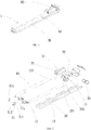
- the squeezer includes a pair of rolling shafts 10, a driving device 20 and a mounting bracket 30.
- Each rolling shaft 10 includes mounting parts 11 at the ends thereof and a squeezing segment 12 between the mounting parts 11.
- the mounting parts 11 and the squeezing segment 12 are integral, however they can also be formed separately and assembled together.
- the rolling shaft 10 is long rod-shaped, and its dimension in the axial direction is much larger than its dimension in the radial direction, and the length of the mounting part 11 is much smaller than that of the squeezing segment 12.
- the squeezing segment 12 is used to contact the bag body of the liner bag 101 (as shown in Figure 7 ), thereby squeezing the bag body, which will be described in detail below.
- the squeezing segment 12 includes a supporting shaft 121 and an elastic body 122 surrounding the supporting shaft 121.
- the elastic body 122 is an elastic soft body made of rubber, resin, or other high-molecular elastic materials.
- the elastic body 122 is cylindrical in shape, and has an inner cavity with an inner diameter matching the outer diameter of the supporting rod 121.
- the supporting rod 121 inserts into the inner cavity of the elastic body 122.
- the outer surface of the supporting shaft 121 can be coated with glue.
- the elastic body 122 is wrapped around and attached to the entire outer surface of the supporting shaft 121, so that when the supporting shaft 121 rotates under the driving of the driving device, the elastic body 122 rotates synchronously.
- the elastic body 122 is integrated with the support shaft 121 by injection molding.
- the elastic body 122 of the rolling shaft 10 can also be other shape, such as ellipse, triangle, or square.
- the mounting part 11 is cylindrical shaft, so as to rotatably mounted in the mounting bracket 30.
- the supporting shaft 121 is generally cylindrical, that is, the outer diameter of the supporting shaft is constant in the axial direction; while the outer diameter of the elastic body 122 changes uniformly in the axial direction, thereby forming an elastic body with a taper.
- the outer diameter of the elastic body 122 can also be substantially constant in the axial direction (as shown in Figure 4 ), or only the outer diameter of a part of the elastic body 122 changes uniformly in the axial direction.
- the mounting bracket 30 includes two first bases 31, two supporting rods 32 and a second base 33.
- the two supporting rods 32 connect two first bases 31 with the second base 33, that is, two ends of the supporting rod 32 are connected with the first base 31 and the second base 33 respectively.
- the first base 31 has a concave recess 311 and a mounting hole 312.
- the second base 33 has a recess 331, an upper mounting hole 333, and a lower mounting hole 332.
- the mounting parts 11 at two ends of the rolling shaft 10 are mounted rotatably in the mounting holes 312 and 332 respectively, and the two ends of the squeezing segment 12 are received in the recesses 311 and 331 respectively, so that during squeezing, the ends of the squeezing segment 12 will not contact the object clamped (for example, the liner bag 101). That is, the recesses 311 and 331 function as protective parts for the ends of the squeezing segment 12, so as to ensure that the elastic body of the squeezing segment 12 will not be separated from the supporting shaft or being damaged during squeezing.
- the length of each of the two ends of the squeezing segment 12 received in the recesses 311 and 331 is 25mm-60mm.
- the length of each of the two ends of the squeezing segment 12 received in the recesses 311 and 331 (protective parts) is 35mm-50mm.
- the length of each of the two ends of the squeezing segment 12 received in the recesses 311 and 331 is 40mm.
- the length of each end of the squeeze segment 12 received in the recesses 311 and 331 is 1/20 to 1/16 of the total length of the squeezing segment 12.
- the squeezing segment of one of the pair of rolling shafts 10 received in the recess 311 of the first base 31 and the squeezing segment of the other received in the recess of first base 31 are not in contact with each other; and the squeezing segment of one of the pair of rolling shafts 10 received in the recess of the second base 33 and the squeezing segment of the other received in the recess 331 of the second base 33 are not in contact with each other. Therefore, during the working process, the ends of the pair of rolling shafts will not rub against each other, thereby ensuring that the elastic body of the squeezing segment 12 will not be damaged or separated.
- the mounting bracket 30 can also has other configurations.
- the supporting rod 32 can be eliminated, the first base 31 can be an integral structure, or the second base 33 can have two separate parts.
- the first base 31 is provided with a locking mechanism.
- one of the first bases 31 is provided with a threaded through hole 313a, and the other is provided with a threaded hole 313b.
- the locking spanner 314 can be screwed into the threaded hole 313b via the threaded through hole 313a so as to operatively lock the pair of rolling shafts 10 together, and vice versa.
- the threaded hole 313b can be a through hole or a blind hole.
- the locking mechanism can also in other configurations, for example locking by buckling.
- the driving device 20 includes a motor 21, a reducer 22, and a transmission gear 23.
- the motor 21 and the reducer 22 are mounted on the mounting bracket 30.
- the reducer 22 is provided in the second base 33.
- One end of the motor 21 is mounted in the upper recess 332 of the second base 33, that is, the motor 21 is mounted above the rolling shaft 10, and the output shaft thereof extends parallel to the axial direction of the rolling shaft 10 and is drivingly connected with the reducer 22.
- the output shaft of the reducer is connected with the mounting part of the rolling shaft, so that the motor drives the reducer to rotate, and then drives the rolling shaft to rotate.
- the reducer 22 and the second base 33 can be formed separately and fixed together by a fixing device.
- the motor 21 can also be mounted above the rolling shaft 10 and perpendicular to the rolling shaft (as shown in Figure 7 ), that is, the output shaft of the motor 21 extends perpendicular to the axial direction of the rolling shaft and is drivingly connected with the reducer 22.
- the reducer 22 and the end of one of the supporting shaft 121 are drivingly engaged, for example, the end of one of the supporting shaft 121 is engaged in the driving slot 221 of the reducer 22.
- the transmitting gears are provided on the mounting parts 11 of the two supporting shaft 121 respectively, so that when the two rolling shafts 10 are locked together, the transmitting gears on the two rolling shafts 11 are engaged with each other.
- the transmitting gear 23 is in the lower recess 331 of the second base 33.
- the driving device 20 may not include the transmitting gear 23.
- two driving slots may be provided in the reducer, which are respectively drivingly engaged with the ends of the pair of rolling shafts 10.
- the second embodiment of this invention is described reference to figures 1, 2 , 4 and 5 .
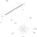
- the supporting shaft 121 in the squeeze segment 12 of the rolling shaft 10 is not cylindrical, but has a protective device for preventing relative rotation between the supporting shaft 121 and the elastic body 122, so as to prevent the elastic body 122 from separating from the supporting shaft 121.
- the outer surface of the supporting shaft 121 has four grooves 1211 extending in the axial direction, and opposite flanges 1211a are provided at the opening of each groove 1211, that is, the groove 1211 is substantially C-shaped.
- the flanges 1211a is used to prevent the supporting shaft 121 and the elastic body from rotating relatively, thereby prevent the elastic body 122 from separating from the supporting shaft 121.
- the number of the grooves 1211 is not limited to the number shown in figures, it can be 3, 5, or 6, etc.; or the grooves 1211 may also be provided only on the position in the supporting shaft 121 in the squeezing segment 12 where corresponds to the ends of the elastic body 122.
- the protective structure may also adopt other structures, such as a concave-convex structure provided on an outer surface of both end parts of the supporting shaft 121 and the inner surface of the elastic body 122.
- the mounting part 11 is not integrally formed with the supporting shaft 121 of the squeezing segment 12, but is sleeved over the supporting shaft 121.
- the mounting part 11 and the supporting shaft 121 of the squeezing segment 12 can also be formed integrally (as shown in the first embodiment).
- the supporting shaft 121 has a function of preventing the elastic body 122 from separating from it in the second embodiment, that is, protecting the squeezing segment 12 from being damaged and separating from it during the squeezing process. Therefore, two ends of the squeezing segment 12 of the rolling shaft 10 are not needed to be received in the recess 311 of the first base 31 and the recess 331 of the second base 33 (as shown in Figure 2 ).
- Figure 7 is a perspective view of the discharge system according to the embodiment of this invention.
- Figure 8 is an sectional view of the discharge system in figure 7 .
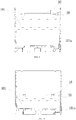
- Figures 9-11 are the cross-section views of the fluid discharge system according to the embodiment of this invention, showing the different phases during fluid discharging.
- the fluid discharge system may includes a container 100, a liner bag 101 and a squeezer 1.
- the container 100 is generally an intermediate bulk container.
- the liner bag 101 is provided with a discharge port 101a and is installed in the container 100.
- the squeezer 1 includes a pair of rolling shafts 10 and a driving device 20. With reference to Figures 7-11 , the discharge process of the fluid discharge system will be described. Firstly, the liner bag 101 is clamped between the pair of rolling shafts 10 (as shown in Figure 7 ).
- the pair of rolling shafts 10 are separated by the locking spanner, and then the upper part of the liner bag 101 is clamped in the squeezer 1 of the container 100, then the pair of rolling shafts 10 are locked together by the locking spanner.
- the driving device 20 is activated, when driven by the driving device 20, the pair of rolling shafts 10 of the squeezer rotate downwardly and oppositely and squeeze the bag of the liner bag 101, so as to squeeze the liquid in the liner bag 101, and discharge the liquid from the discharge port 101a.
- the pair of rolling shafts 10 automatically descend with the liquid level descending through the driving of the driving device 20 and squeeze the liquid (as shown in Figures 9-11 ).
- the elastic body and supporting shaft of the rolling shaft 10 will not be separated from each other or damaged.
- Figures 12-13 are schematic diagrams showing the variant of the squeezer in Figure 4 .
- the differences between the embodiment shown in Figures 12-13 and the embodiment shown in Figure 4 are the structure of the mounting bracket 2030, in particular the structure of the supporting rod.
- the cross section of the supporting rod 2032 in the squeezer 200 is different from that of the supporting rod shown in Figures 2 and 4 .
- the cross section of the supporting rod 2032 is U-shaped.
- the supporting rod 2032 can surround the outer side of the rolling shaft, preventing the outer side of the rolling shaft from contacting the clamped object, that is, spacing the outer side of the rolling shaft from the clamped object, and further preventing hands of the operator from being clamped by the rolling shafts.
- the outer side refers to the side of the rolling shaft opposite to the side contacting the clamped object.
- the cross section of the supporting rod 2032 can also be C-shaped, or the protective part can have other shapes or configurations, as long as it can surround the outer side of the rolling shaft, such that during the squeezing of the squeezer, and the outer side of the rolling shaft is separate from the clamped object.
Landscapes
- Engineering & Computer Science (AREA)
- Mechanical Engineering (AREA)
- Reciprocating Pumps (AREA)
- Rolls And Other Rotary Bodies (AREA)
- Tubes (AREA)
- Apparatuses For Bulk Treatment Of Fruits And Vegetables And Apparatuses For Preparing Feeds (AREA)
- Extrusion Moulding Of Plastics Or The Like (AREA)
Applications Claiming Priority (2)
| Application Number | Priority Date | Filing Date | Title |
|---|---|---|---|
| CN201710656555.5A CN107472723B (zh) | 2017-08-03 | 2017-08-03 | 流体排放系统及其挤推器 |
| PCT/CN2018/097328 WO2019024769A1 (fr) | 2017-08-03 | 2018-07-27 | Système d'évacuation de fluide et dispositif de pression et de poussée associé |
Publications (4)
| Publication Number | Publication Date |
|---|---|
| EP3663233A1 true EP3663233A1 (fr) | 2020-06-10 |
| EP3663233A4 EP3663233A4 (fr) | 2020-12-02 |
| EP3663233B1 EP3663233B1 (fr) | 2025-06-25 |
| EP3663233C0 EP3663233C0 (fr) | 2025-06-25 |
Family
ID=60598588
Family Applications (1)
| Application Number | Title | Priority Date | Filing Date |
|---|---|---|---|
| EP18841657.2A Active EP3663233B1 (fr) | 2017-08-03 | 2018-07-27 | Système d'évacuation de fluide et dispositif de pression et de poussée associé |
Country Status (8)
| Country | Link |
|---|---|
| US (1) | US11235922B2 (fr) |
| EP (1) | EP3663233B1 (fr) |
| JP (1) | JP6943508B2 (fr) |
| CN (1) | CN107472723B (fr) |
| AU (1) | AU2018310374C1 (fr) |
| ES (1) | ES3033958T3 (fr) |
| PL (1) | PL3663233T3 (fr) |
| WO (1) | WO2019024769A1 (fr) |
Cited By (1)
| Publication number | Priority date | Publication date | Assignee | Title |
|---|---|---|---|---|
| PL132790U1 (pl) * | 2025-06-10 | 2026-01-19 | Kujawa Jacek Kujawa - Jacek Kujawa | Prasa do wyciskania materiałów budowlanych z opakowań |
Families Citing this family (3)
| Publication number | Priority date | Publication date | Assignee | Title |
|---|---|---|---|---|
| CN107472723B (zh) * | 2017-08-03 | 2024-07-02 | 上海鸿研物流技术有限公司 | 流体排放系统及其挤推器 |
| NL2021873B9 (en) * | 2018-10-25 | 2020-07-21 | Mega Inliner Int Group Bv | Liquid stabilizing inliner for a tank container |
| US20250033870A1 (en) * | 2023-07-26 | 2025-01-30 | Fol-Da-Tank, Llc | Rapid release device for folding frame tank drain sleeves and related systems and methods |
Family Cites Families (29)
| Publication number | Priority date | Publication date | Assignee | Title |
|---|---|---|---|---|
| US4627551A (en) * | 1984-03-05 | 1986-12-09 | Oatey Co. | Dispenser system and method for dispensing putty-like material |
| US5118011A (en) | 1990-12-05 | 1992-06-02 | Oatey Co. | Food roller dispenser |
| JP3002156U (ja) | 1994-03-18 | 1994-09-20 | 洋 金島 | 練歯磨自動供給装置 |
| US5490613A (en) * | 1994-07-07 | 1996-02-13 | The Clorox Company | Viscous fluid dispenser |
| US5765723A (en) | 1996-08-05 | 1998-06-16 | A. R. Arena Products, Inc. | Bag evacuator |
| JP3043307U (ja) | 1997-04-14 | 1997-11-18 | 株式会社前田製作所 | コンテナ内袋回収機構ならびにそのためのコンテナおよび内袋 |
| US5875929A (en) * | 1998-01-27 | 1999-03-02 | Nguyen; Dung T. | Toothpaste dispensing apparatus |
| US6467652B2 (en) * | 1998-01-28 | 2002-10-22 | A. R. Arena Products, Inc. | Discharge of pumpable material from shipper bags |
| US6296150B1 (en) * | 1999-02-25 | 2001-10-02 | Barry Farris | Medicinal dosing apparatus and method |
| US6196420B1 (en) | 1999-09-09 | 2001-03-06 | Nestec S.A. | Pumpless dispenser for viscous food products |
| PT1385751E (pt) | 2001-01-18 | 2009-05-28 | Ar Arena Products Inc | Descarga de topo de material bombeável de sacos de carga |
| US6659309B2 (en) * | 2001-12-05 | 2003-12-09 | International Dispensing Corporation | Portion control dispenser |
| FR2851242B1 (fr) * | 2003-02-13 | 2005-10-21 | Rhodia Chimie Sa | Procede de vidange d'un conteneur souple renfermant un produit visqueux |
| US7086428B2 (en) * | 2003-05-01 | 2006-08-08 | Lancer Partnership, Ltd. | Evacuation system |
| US7111758B1 (en) * | 2004-07-27 | 2006-09-26 | Monks Harold R | Toothpaste dispensing apparatus |
| EP1634689B1 (fr) * | 2004-09-08 | 2013-05-22 | Leister Technologies AG | Dispositif de soudage par extrusion portable |
| US7798365B2 (en) | 2005-08-18 | 2010-09-21 | Portec Rail Products, Inc. | Bulk transfer dispensing device and method |
| DE102006046501A1 (de) * | 2006-09-29 | 2008-04-03 | Werner & Pfleiderer Lebensmitteltechnik Gmbh | Vorrichtung zur Herstellung eines Teigbandes aus einem Roh-Teigband sowie Set aus Planetenwalzen zum Einsatz in einer derartigen Vorrichtung |
| EP2170760A4 (fr) * | 2007-06-22 | 2015-01-28 | Rich Products Corp | Distributeur de garnitures |
| FI20105003L (fi) * | 2010-01-04 | 2011-07-05 | Fluid Bag Ab Oy | Tyhjennyslaite |
| JP5490660B2 (ja) * | 2010-10-29 | 2014-05-14 | 株式会社吉野工業所 | 2連チューブ押出装置 |
| FI124079B (fi) | 2011-09-02 | 2014-03-14 | Pro Hydro Ab Oy | Elastisen pakkaussäiliön purkauslaite ja menetelmä elastisen säiliön purkamiseksi |
| US9359132B2 (en) | 2014-04-08 | 2016-06-07 | Grayling Industries, Inc. | Liner sump dispensing system |
| CN104097853B (zh) | 2014-06-20 | 2017-09-26 | 上海鸿研物流技术有限公司 | 用于中型散装容器的内衬袋 |
| CN203997146U (zh) * | 2014-08-15 | 2014-12-10 | 英利能源(中国)有限公司 | 一种袋装硅胶挤出装置 |
| US10472168B2 (en) * | 2015-10-05 | 2019-11-12 | Ilc Dover Ip, Inc. | Flexible container liner wringing device |
| CN107697486B (zh) | 2016-08-08 | 2020-10-20 | 上海鸿研物流技术有限公司 | 挤推器及流体排放系统和方法 |
| CN107472723B (zh) * | 2017-08-03 | 2024-07-02 | 上海鸿研物流技术有限公司 | 流体排放系统及其挤推器 |
| CN207275422U (zh) * | 2017-08-03 | 2018-04-27 | 上海鸿研物流技术有限公司 | 流体排放系统及其挤推器 |
-
2017
- 2017-08-03 CN CN201710656555.5A patent/CN107472723B/zh active Active
-
2018
- 2018-07-27 PL PL18841657.2T patent/PL3663233T3/pl unknown
- 2018-07-27 WO PCT/CN2018/097328 patent/WO2019024769A1/fr not_active Ceased
- 2018-07-27 EP EP18841657.2A patent/EP3663233B1/fr active Active
- 2018-07-27 AU AU2018310374A patent/AU2018310374C1/en active Active
- 2018-07-27 JP JP2020505372A patent/JP6943508B2/ja active Active
- 2018-07-27 US US16/636,301 patent/US11235922B2/en active Active
- 2018-07-27 ES ES18841657T patent/ES3033958T3/es active Active
Cited By (1)
| Publication number | Priority date | Publication date | Assignee | Title |
|---|---|---|---|---|
| PL132790U1 (pl) * | 2025-06-10 | 2026-01-19 | Kujawa Jacek Kujawa - Jacek Kujawa | Prasa do wyciskania materiałów budowlanych z opakowań |
Also Published As
| Publication number | Publication date |
|---|---|
| ES3033958T3 (en) | 2025-08-11 |
| US20210179347A1 (en) | 2021-06-17 |
| CN107472723B (zh) | 2024-07-02 |
| EP3663233B1 (fr) | 2025-06-25 |
| EP3663233C0 (fr) | 2025-06-25 |
| JP2020528854A (ja) | 2020-10-01 |
| AU2018310374C1 (en) | 2022-03-03 |
| CN107472723A (zh) | 2017-12-15 |
| WO2019024769A1 (fr) | 2019-02-07 |
| PL3663233T3 (pl) | 2025-08-18 |
| JP6943508B2 (ja) | 2021-10-06 |
| AU2018310374A1 (en) | 2020-03-12 |
| US11235922B2 (en) | 2022-02-01 |
| EP3663233A4 (fr) | 2020-12-02 |
| AU2018310374B2 (en) | 2021-11-11 |
Similar Documents
| Publication | Publication Date | Title |
|---|---|---|
| US11235922B2 (en) | Fluid discharge system and squeezer thereof | |
| EP3663232B1 (fr) | Système de drainage de fluide et appareil de compression et de poussée associé | |
| AU2017309920B2 (en) | Extrusion and pushing device and liquid discharge system and method | |
| US9238544B2 (en) | Article and method for sealing a collapsible container | |
| WO2020187203A1 (fr) | Système de vidange de fluide et appareil de compression et de poussée associé | |
| EP3162452A2 (fr) | Appareil applicateur, dispositifs pleine bouche, récipients pliables et procédés | |
| EP2251655A1 (fr) | Conteneur de distribution | |
| JP7545179B2 (ja) | 排出システム及びその押出し器 | |
| CN207275421U (zh) | 流体排放系统及其挤推器 | |
| CN207275422U (zh) | 流体排放系统及其挤推器 | |
| CA2285503A1 (fr) | Distributeur de fluides visqueux contenus dans des emballages souples | |
| US11548772B2 (en) | Liquid transfer device and method of use | |
| FI83950B (fi) | Behaollare avsedd foer en pumpningsbar produkt. | |
| CN210392229U (zh) | 流体排放系统及其挤推器 | |
| CN207129945U (zh) | 一种旋转式化工分装装置 | |
| CN101730650A (zh) | 用于柔性袋的填充/排出结构和带有该结构的柔性袋 | |
| GB2434137A (en) | Collapsible container suitable for liquids, gels and pastes | |
| TH81650A (th) | ภาชนะบรรจุจาระบี |
Legal Events
| Date | Code | Title | Description |
|---|---|---|---|
| STAA | Information on the status of an ep patent application or granted ep patent |
Free format text: STATUS: THE INTERNATIONAL PUBLICATION HAS BEEN MADE |
|
| PUAI | Public reference made under article 153(3) epc to a published international application that has entered the european phase |
Free format text: ORIGINAL CODE: 0009012 |
|
| STAA | Information on the status of an ep patent application or granted ep patent |
Free format text: STATUS: REQUEST FOR EXAMINATION WAS MADE |
|
| 17P | Request for examination filed |
Effective date: 20200303 |
|
| AK | Designated contracting states |
Kind code of ref document: A1 Designated state(s): AL AT BE BG CH CY CZ DE DK EE ES FI FR GB GR HR HU IE IS IT LI LT LU LV MC MK MT NL NO PL PT RO RS SE SI SK SM TR |
|
| AX | Request for extension of the european patent |
Extension state: BA ME |
|
| DAV | Request for validation of the european patent (deleted) | ||
| DAX | Request for extension of the european patent (deleted) | ||
| A4 | Supplementary search report drawn up and despatched |
Effective date: 20201029 |
|
| RIC1 | Information provided on ipc code assigned before grant |
Ipc: B65D 90/04 20060101ALI20201023BHEP Ipc: B65D 77/06 20060101ALI20201023BHEP Ipc: B65D 35/28 20060101ALI20201023BHEP Ipc: B65D 90/00 20060101ALI20201023BHEP Ipc: B67D 7/02 20100101ALI20201023BHEP Ipc: B65D 88/54 20060101AFI20201023BHEP |
|
| STAA | Information on the status of an ep patent application or granted ep patent |
Free format text: STATUS: EXAMINATION IS IN PROGRESS |
|
| 17Q | First examination report despatched |
Effective date: 20220906 |
|
| GRAP | Despatch of communication of intention to grant a patent |
Free format text: ORIGINAL CODE: EPIDOSNIGR1 |
|
| STAA | Information on the status of an ep patent application or granted ep patent |
Free format text: STATUS: GRANT OF PATENT IS INTENDED |
|
| INTG | Intention to grant announced |
Effective date: 20250213 |
|
| GRAS | Grant fee paid |
Free format text: ORIGINAL CODE: EPIDOSNIGR3 |
|
| GRAF | Information related to payment of grant fee modified |
Free format text: ORIGINAL CODE: EPIDOSCIGR3 |
|
| GRAA | (expected) grant |
Free format text: ORIGINAL CODE: 0009210 |
|
| STAA | Information on the status of an ep patent application or granted ep patent |
Free format text: STATUS: THE PATENT HAS BEEN GRANTED |
|
| AK | Designated contracting states |
Kind code of ref document: B1 Designated state(s): AL AT BE BG CH CY CZ DE DK EE ES FI FR GB GR HR HU IE IS IT LI LT LU LV MC MK MT NL NO PL PT RO RS SE SI SK SM TR |
|
| REG | Reference to a national code |
Ref country code: GB Ref legal event code: FG4D |
|
| REG | Reference to a national code |
Ref country code: CH Ref legal event code: EP |
|
| REG | Reference to a national code |
Ref country code: CH Ref legal event code: EP |
|
| REG | Reference to a national code |
Ref country code: IE Ref legal event code: FG4D |
|
| U01 | Request for unitary effect filed |
Effective date: 20250625 |
|
| U07 | Unitary effect registered |
Designated state(s): AT BE BG DE DK EE FI FR IT LT LU LV MT NL PT RO SE SI Effective date: 20250701 |
|
| U20 | Renewal fee for the european patent with unitary effect paid |
Year of fee payment: 8 Effective date: 20250701 |
|
| REG | Reference to a national code |
Ref country code: ES Ref legal event code: FG2A Ref document number: 3033958 Country of ref document: ES Kind code of ref document: T3 Effective date: 20250811 |
|
| PGFP | Annual fee paid to national office [announced via postgrant information from national office to epo] |
Ref country code: ES Payment date: 20250804 Year of fee payment: 8 |
|
| PG25 | Lapsed in a contracting state [announced via postgrant information from national office to epo] |
Ref country code: NO Free format text: LAPSE BECAUSE OF FAILURE TO SUBMIT A TRANSLATION OF THE DESCRIPTION OR TO PAY THE FEE WITHIN THE PRESCRIBED TIME-LIMIT Effective date: 20250925 Ref country code: GR Free format text: LAPSE BECAUSE OF FAILURE TO SUBMIT A TRANSLATION OF THE DESCRIPTION OR TO PAY THE FEE WITHIN THE PRESCRIBED TIME-LIMIT Effective date: 20250926 |
|
| PGFP | Annual fee paid to national office [announced via postgrant information from national office to epo] |
Ref country code: PL Payment date: 20250630 Year of fee payment: 8 |
|
| PGFP | Annual fee paid to national office [announced via postgrant information from national office to epo] |
Ref country code: GB Payment date: 20250702 Year of fee payment: 8 |
|
| PG25 | Lapsed in a contracting state [announced via postgrant information from national office to epo] |
Ref country code: HR Free format text: LAPSE BECAUSE OF FAILURE TO SUBMIT A TRANSLATION OF THE DESCRIPTION OR TO PAY THE FEE WITHIN THE PRESCRIBED TIME-LIMIT Effective date: 20250625 |
|
| PG25 | Lapsed in a contracting state [announced via postgrant information from national office to epo] |
Ref country code: RS Free format text: LAPSE BECAUSE OF FAILURE TO SUBMIT A TRANSLATION OF THE DESCRIPTION OR TO PAY THE FEE WITHIN THE PRESCRIBED TIME-LIMIT Effective date: 20250925 |
|
| PG25 | Lapsed in a contracting state [announced via postgrant information from national office to epo] |
Ref country code: IS Free format text: LAPSE BECAUSE OF FAILURE TO SUBMIT A TRANSLATION OF THE DESCRIPTION OR TO PAY THE FEE WITHIN THE PRESCRIBED TIME-LIMIT Effective date: 20251025 |
|
| PG25 | Lapsed in a contracting state [announced via postgrant information from national office to epo] |
Ref country code: SM Free format text: LAPSE BECAUSE OF FAILURE TO SUBMIT A TRANSLATION OF THE DESCRIPTION OR TO PAY THE FEE WITHIN THE PRESCRIBED TIME-LIMIT Effective date: 20250625 |
|
| PG25 | Lapsed in a contracting state [announced via postgrant information from national office to epo] |
Ref country code: CZ Free format text: LAPSE BECAUSE OF FAILURE TO SUBMIT A TRANSLATION OF THE DESCRIPTION OR TO PAY THE FEE WITHIN THE PRESCRIBED TIME-LIMIT Effective date: 20250625 |
|
| PG25 | Lapsed in a contracting state [announced via postgrant information from national office to epo] |
Ref country code: SK Free format text: LAPSE BECAUSE OF FAILURE TO SUBMIT A TRANSLATION OF THE DESCRIPTION OR TO PAY THE FEE WITHIN THE PRESCRIBED TIME-LIMIT Effective date: 20250625 |
|
| REG | Reference to a national code |
Ref country code: CH Ref legal event code: H13 Free format text: ST27 STATUS EVENT CODE: U-0-0-H10-H13 (AS PROVIDED BY THE NATIONAL OFFICE) Effective date: 20260224 |
|
| PG25 | Lapsed in a contracting state [announced via postgrant information from national office to epo] |
Ref country code: MC Free format text: LAPSE BECAUSE OF FAILURE TO SUBMIT A TRANSLATION OF THE DESCRIPTION OR TO PAY THE FEE WITHIN THE PRESCRIBED TIME-LIMIT Effective date: 20250625 |
|
| PG25 | Lapsed in a contracting state [announced via postgrant information from national office to epo] |
Ref country code: CH Free format text: LAPSE BECAUSE OF NON-PAYMENT OF DUE FEES Effective date: 20250731 |
|
| PLBE | No opposition filed within time limit |
Free format text: ORIGINAL CODE: 0009261 |
|
| STAA | Information on the status of an ep patent application or granted ep patent |
Free format text: STATUS: NO OPPOSITION FILED WITHIN TIME LIMIT |
|
| REG | Reference to a national code |
Ref country code: CH Ref legal event code: L10 Free format text: ST27 STATUS EVENT CODE: U-0-0-L10-L00 (AS PROVIDED BY THE NATIONAL OFFICE) Effective date: 20260507 |