EP3663466A1 - Mauerkrone für bahnsteig mit vertiefter unterseite - Google Patents
Mauerkrone für bahnsteig mit vertiefter unterseite Download PDFInfo
- Publication number
- EP3663466A1 EP3663466A1 EP19188690.2A EP19188690A EP3663466A1 EP 3663466 A1 EP3663466 A1 EP 3663466A1 EP 19188690 A EP19188690 A EP 19188690A EP 3663466 A1 EP3663466 A1 EP 3663466A1
- Authority
- EP
- European Patent Office
- Prior art keywords
- coping unit
- coping
- recesses
- unit
- tactile plate
- Prior art date
- Legal status (The legal status is an assumption and is not a legal conclusion. Google has not performed a legal analysis and makes no representation as to the accuracy of the status listed.)
- Withdrawn
Links
- 230000010485 coping Effects 0.000 title claims abstract description 80
- 238000000034 method Methods 0.000 claims description 8
- 239000004567 concrete Substances 0.000 description 16
- 239000000853 adhesive Substances 0.000 description 6
- 230000001070 adhesive effect Effects 0.000 description 6
- 239000000203 mixture Substances 0.000 description 6
- 238000005266 casting Methods 0.000 description 5
- 238000004519 manufacturing process Methods 0.000 description 5
- 230000009286 beneficial effect Effects 0.000 description 4
- 239000000758 substrate Substances 0.000 description 4
- 239000004568 cement Substances 0.000 description 3
- 238000009434 installation Methods 0.000 description 3
- 238000012423 maintenance Methods 0.000 description 3
- 239000000463 material Substances 0.000 description 3
- 239000004570 mortar (masonry) Substances 0.000 description 3
- 239000002253 acid Substances 0.000 description 2
- 239000007788 liquid Substances 0.000 description 2
- 239000003973 paint Substances 0.000 description 2
- 230000000704 physical effect Effects 0.000 description 2
- 239000004033 plastic Substances 0.000 description 2
- 229920003023 plastic Polymers 0.000 description 2
- 239000005060 rubber Substances 0.000 description 2
- 238000010008 shearing Methods 0.000 description 2
- 229920001875 Ebonite Polymers 0.000 description 1
- 229910000831 Steel Inorganic materials 0.000 description 1
- 230000015572 biosynthetic process Effects 0.000 description 1
- 239000000919 ceramic Substances 0.000 description 1
- 238000010276 construction Methods 0.000 description 1
- 230000003247 decreasing effect Effects 0.000 description 1
- 229910052571 earthenware Inorganic materials 0.000 description 1
- 239000000835 fiber Substances 0.000 description 1
- 239000011521 glass Substances 0.000 description 1
- 239000010438 granite Substances 0.000 description 1
- 239000011372 high-strength concrete Substances 0.000 description 1
- 230000001788 irregular Effects 0.000 description 1
- 239000004579 marble Substances 0.000 description 1
- 239000002184 metal Substances 0.000 description 1
- 210000002445 nipple Anatomy 0.000 description 1
- 229920001296 polysiloxane Polymers 0.000 description 1
- 230000008092 positive effect Effects 0.000 description 1
- 230000001105 regulatory effect Effects 0.000 description 1
- 229920005989 resin Polymers 0.000 description 1
- 239000011347 resin Substances 0.000 description 1
- -1 sandstone Substances 0.000 description 1
- 239000010454 slate Substances 0.000 description 1
- 239000010959 steel Substances 0.000 description 1
- 238000005728 strengthening Methods 0.000 description 1
- 239000002344 surface layer Substances 0.000 description 1
Images


Classifications
-
- E—FIXED CONSTRUCTIONS
- E01—CONSTRUCTION OF ROADS, RAILWAYS, OR BRIDGES
- E01F—ADDITIONAL WORK, SUCH AS EQUIPPING ROADS OR THE CONSTRUCTION OF PLATFORMS, HELICOPTER LANDING STAGES, SIGNS, SNOW FENCES, OR THE LIKE
- E01F1/00—Construction of station or like platforms or refuge islands or like islands in traffic areas, e.g. intersection or filling-station islands; Kerbs specially adapted for islands in traffic areas
-
- B—PERFORMING OPERATIONS; TRANSPORTING
- B61—RAILWAYS
- B61B—RAILWAY SYSTEMS; EQUIPMENT THEREFOR NOT OTHERWISE PROVIDED FOR
- B61B1/00—General arrangement of stations, platforms, or sidings; Railway networks; Rail vehicle marshalling systems
- B61B1/02—General arrangement of stations and platforms including protection devices for the passengers
Definitions
- the invention relates to an improved coping unit and a method of production thereof, the coping unit being suitable for use on raised platforms such as railway platforms.
- Raised platforms such as those found at railway stations traditionally incorporate a series of mutually abutting rectangular coping units extending along the outer edge to delineate the platform proximal to the track.
- the coping units are secured to the platform structure with a cement-based mortar bedding and the front end of a unit partially extends away from the platform to form a projecting lip.
- the projecting lip acts to at least partially bridge the gap between the platform and the trains.
- coping units such as those described, have a number of physical properties and tolerances that they must meet in order to pass safety regulations.
- the current invention seeks to at least partially overcome the above limitations, providing a lighter weight coping unit that retains the longevity of a current concrete unit but is much easier to transport and install, and is less susceptible to movement.
- the invention provides a coping unit suitable for use on a raised platform comprising an under-face incorporating a plurality of regular, preferably non-continuous recesses.
- This configuration is highly beneficial because the recesses reduce the volume of material required to manufacture the coping unit and therefore decrease the weight of the coping unit.
- the recesses increase the surface area of contact between the coping unit and a bonding adhesive (usually a cement-based bedding mortar), used to secure the coping unit in position and therefore increase the strength of the attachment.
- the recesses provide a surface against which the concrete setting within the recesses can abut, reducing the possibility of the coping unit slipping parallel to the surface of the platform.
- the recesses provide an area for the bonding adhesive to push into during installation making the coping unit easier to install.
- the sides of the recesses are at an angle of between about 15 and 45 degrees. This is beneficial because the angled sides of the recesses assist in releasing the units from the mould, during casting. In addition, the angled sides reduce the possibility of the pinnacles of the sides shearing off, producing a stronger attachment.
- the recesses tesselate to form a regular pattern. This is beneficial because the tesselation enables more recesses to be included within a coping unit, and therefore reduces the weight, whilst not impairing the structural strength, of the unit.
- the invention provides a method of constructing a coping unit suitable for use on a raised platform, the method being characterised by the step of bringing together an initially separate tactile plate and the previously cast body of the unit before the body has fully set.
- This is highly beneficial because casting the tactile plate directly into the coping unit removes the need to separately affix it. This saves time in manufacture and also removes the possibility of human error and lifetime issues with tactile plate adhesion and maintenance.
- by casting the tactile plate into the coping unit you can ensure there is no lip or ridge between the tactile plate and the top of the coping unit, which may be a tripping hazard.
- the method of the second aspect can be used to produce the coping unit of the first broad independent aspect.
- the invention discloses a lighter weight coping unit, with bottom surface adapted to incorporate a plurality of regularly arrayed recesses.
- the recesses reduce the volume of concrete and therefore the unit mass (compared to flat bottomed coping units) and also providing greater adhesion (greater surface area and bedding key) therefore improving fixity to the substrate. Furthermore, the decreased weight of the units makes them easier to transport and install and less reliant on the competency of the substrate.
- coping unit refers to the unit used to delineate the edge of a raised platform such as at railway stations.
- the coping unit as formed from a standard concrete aggregate mix such as those known in the art.
- the invention is envisaged to function with a range of concrete mixes to provide variable physical properties as required.
- the coping unit may be formed of a lightweight or high strength concrete mix to further enhance the features of the coping unit.
- the invention is not limited to concrete and in an embodiment of the invention the coping unit is made from one of slate, granite, marble, sandstone, ceramic, glass, earthenware, rubber, metal or plastics.
- tactile plate refers to a region of the coping unit with a regular or irregular, pattern of raised or indented relief suitable for providing a tactile or audible indication that a user is near the edge of the raised platform.
- Such units are required due to statutory and safety regulations and can be integrally formed with the coping unit, in fixed attachment with the unit or independently mounted to the platform.
- 'top', 'bottom', 'front', 'back' and 'sides' are defined with respect to the orientation of the coping unit in use, with the front of the coping unit considered as facing away from the platform.
- Figure 1 shows a first embodiment of a coping unit 10 in perspective view.
- the coping unit 10 is generally in the form of a substantially rectangular slab, with a planar top 14, a bottom 16 and sides 18 and 20 respectively extending therebetween.
- a rounded lip 22 curves from the top 14 to the bottom 16, thereby forming an upper edge.
- the lip 22 is coated in a coloured paint to improve the lips' visibility and assist users in identifying the edge of the platform.
- the lip 22 is coated in a chlorinated rubber resin paint.
- the tactile plate 12 is formed from a suitable fibre enforced laminate, plastic or hard rubber material.
- the tactile plate is coated in a rough finishing material to increase the coefficient of friction and reduce the possibility of a person's foot slipping thereon.
- the coping unit 10 does not incorporate a tactile plate 12.
- the coping unit has overall length dimensions of between around 1000mm to 1400mm, of between around 1100mm to around 1300mm, of between about 1150mm to 1200mm.
- the coping unit has width dimensions of between around 800mm to 1050mm, of between around 850mm to around 1000mm, of between around 900mm to around 950mm.
- the coping unit has depth dimensions of between around 80mm to around 110mm, of between around 90mm to around 105mm, of between around 95mm to around 100mm.
- the coping unit has length dimensions of between around 600mm to around 900mm.
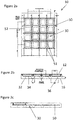
- Figures 2a-c show a first embodiment of a coping unit 10 from multiple side views.
- Figure 2a shows the bottom 16 of the coping unit 10, with the internal structure represented by dashed lines.
- the bottom 16 incorporates a plurality of recesses 30 tessellating to form a regular pattern.
- the coping unit 10 incorporates sixteen recesses 30 in a regular four by four grid.
- the coping unit 10 incorporates recesses 30 in one of: a five by five grid pattern, a six by six grid pattern, a three by four grid pattern or a three by five grid pattern.
- each recess 30 is shaped as a pyramidal frustum, with a square outer edge 32 in the plane of the bottom 16 of the coping unit 10 and a smaller square base 34 at the bottom of the recess 30.
- the outer edge 32 and the base 34 are one of; rectangular, pentagonal, hexagonal, heptagonal or any suitable non-continuous geometric shape.
- the sides 36 of the recess 30, adjoining the outer edge 32 to the base 34 are sloped to form a bevel.
- the bevelled sides 36 are between 45 and 15 degrees from vertical.
- the bevelled sides 36 are between 35 and 25 degrees from vertical.
- the sides 36 are bevelled at an angle of 30 degrees.
- the base 34 of the recess 30 is centred within the outer edge 32 such that each bevelled side 36 has an identical length and angle of slope.
- the base 34 of the recesses 30, is offset within the outer edge 32 such that at least one of the bevelled sides 36 has a steeper angle than the others.
- the outer edges 32 of the recesses 30 have a width dimension of between about 150mm to about 190mm, of between about 160mm to about 180mm.
- the base 34 of the recesses 30 has a width dimension of between about 90mm to about 130mm, of between about 100mm to about 120mm, of between about 110mm to about 115mm.
- the recesses 30 have a depth of between about 40mm to about 60mm. In a further preferred embodiment, the recesses have a depth of about 50mm.
- the recesses 30 have multiple positive effects on the functioning of the coping unit 10.
- an adhesive usually a cement-based mortar bed
- This mix adheres the coping unit to the substrate surface to which it is secured, and pushes up into the recess 30 before setting and fixing the coping unit 10 in place.
- the recesses 30 increase the surface area of contact between the coping unit 10 and the adhesive mix and thereby increase the strength of the attachment of the coping unit to the substrate.
- the bevelled sides 36 of the recesses 30 provide a surface against which the bedding adhesive within the recesses 30 can abut, reducing the possibility of the coping moving laterally parallel to the surface of the platform.
- the angle of the bevelled sides 36 reduces the chance of the bevelled sides 36 shearing due to lateral forces, further strengthening the attachment of the coping unit to the platform.
- the increased surface area of the coping unit bottom provides a greater bond with the bedding adhesive to resist vertical (uplift) movement of the coping unit.
- the recesses 30 in the coping unit 10 reduce the overall weight of the unit by reducing the volume of concrete used in its formation. This results in simplifying transportation and installation, reducing associated lifting and handling issues. This reduction in weight and ease of transportation and installation greatly improves the safety associated with the construction of platforms such as those described.
- a mesh 50 of vertically and horizontally extending resilient fibres is set within the coping unit 10.
- the mesh 50 is a steel mesh welded together at overlap junctions 51.
- the fibres 52 extend within the gaps between the recesses 30 where the concrete is deepest and therefore has the greatest strength.
- Figures 3a and 3b show the first embodiment of a tactile plate 12 from the top and from the end respectively.
- the tactile plate incorporates a number of raised or indented reliefs to provide a standard and regulatory compliant tactile surface as required to warn pedestrians they are nearing the edge of the platform. In some cases, such as when travelling with a wheeled device such as a suitcase, the raised blisters provide an audible indication that the user is nearing the edge of the platform.
- the tactile plate 12 incorporates a plurality of raised nipples 40 arrayed in a regular pattern.
- a plurality of threaded anchors 26 are integrally formed with the tactile plate 12.
- the threaded anchors 26 are secured to the tactile plate and extend below the tactile plate 12 into the coping unit 10 during concrete casting.
- the threaded anchors 26 function to secure the tactile plate 12 to the coping unit 10 but also allow for the subsequent unscrewing and removal of the tactile plate 12 for future replacement.
- the tactile plate 12 incorporates ten threaded anchors 26 disposed around the perimeter.
- the threaded anchors 26 are irregularly disposed along the width of the tactile plate 12 such that they do not coincide with tactile blisters but arranged for ease of future replacement (best shown in Figure 3c ).
- the tactile plate incorporates 10 regularly spaced threaded anchors 26 around the perimeter of the tactile plate 12.
- the tactile plate 12 has, 4, 6, 8 or 12 threaded anchors.
- Figure 3c shows the tactile plate 12 incorporated in the coping unit 10.
- the tactile plate 12 is monolithically set into the concrete before it has set. This has many benefits such as removing the need to cast in a cavity in the top of the coping unit which can then house the tactile plate. This would need to be separately attached, increasing the time of production and introducing another stage of potential human error.
- by casting the tactile plate 12 directly into the wet concrete it ensures that the upper surface of the tactile plate 12 is flush with the top 14 of the coping unit 10, and therefore reduces the possibility of maintenance and/or health & safety issues with an exposed ridge.
- the method of production includes the stages of, adding the tactile plate 12 to the mould prior to or during the addition of the liquid concrete mix.
- silicone inserts are placed within the main concrete mould subsequently to pouring the liquid concrete mix to create the recesses 30.
- an acid etch is applied to the top 14 of the coping unit 10. The acid wash removes the surface layer of the coping unit 10 exposing the aggregate. This increases the coefficient of friction and reducing the possibility of an end user slipping.
Landscapes
- Engineering & Computer Science (AREA)
- Architecture (AREA)
- Civil Engineering (AREA)
- Structural Engineering (AREA)
- Transportation (AREA)
- Mechanical Engineering (AREA)
- Road Paving Structures (AREA)
- Road Signs Or Road Markings (AREA)
Applications Claiming Priority (1)
| Application Number | Priority Date | Filing Date | Title |
|---|---|---|---|
| GB1812318.2A GB2575976B (en) | 2018-07-27 | 2018-07-27 | Railway platform coping unit with recessed underside. |
Publications (1)
| Publication Number | Publication Date |
|---|---|
| EP3663466A1 true EP3663466A1 (de) | 2020-06-10 |
Family
ID=63518262
Family Applications (1)
| Application Number | Title | Priority Date | Filing Date |
|---|---|---|---|
| EP19188690.2A Withdrawn EP3663466A1 (de) | 2018-07-27 | 2019-07-26 | Mauerkrone für bahnsteig mit vertiefter unterseite |
Country Status (2)
| Country | Link |
|---|---|
| EP (1) | EP3663466A1 (de) |
| GB (1) | GB2575976B (de) |
Citations (4)
| Publication number | Priority date | Publication date | Assignee | Title |
|---|---|---|---|---|
| BE552514A (de) * | ||||
| NL8402296A (nl) * | 1984-07-19 | 1986-02-17 | Ballast Nedam Groep N V En Bal | Grondplaat, werkwijze voor het leggen van een grondplaat en werkwijze voor het instellen van het niveau van een grondplaat. |
| JPH07329771A (ja) * | 1994-06-09 | 1995-12-19 | Miyasaka Gomme Kk | プラットホームのステップ構造及びこれに用いるステップ材 |
| GB2490722A (en) * | 2011-05-13 | 2012-11-14 | Colt Ind Services Ltd | Edging product for raised platforms incorporating a tactile surface |
Family Cites Families (2)
| Publication number | Priority date | Publication date | Assignee | Title |
|---|---|---|---|---|
| JPH0382663A (ja) * | 1989-08-25 | 1991-04-08 | Kakegawa Tokushu Concrete Kogyo Kk | プラットホーム嵩上げ工法 |
| GB2565417B (en) * | 2017-06-14 | 2021-09-29 | Pipex Ltd | Improvements in or relating to railway platforms |
-
2018
- 2018-07-27 GB GB1812318.2A patent/GB2575976B/en active Active
-
2019
- 2019-07-26 EP EP19188690.2A patent/EP3663466A1/de not_active Withdrawn
Patent Citations (4)
| Publication number | Priority date | Publication date | Assignee | Title |
|---|---|---|---|---|
| BE552514A (de) * | ||||
| NL8402296A (nl) * | 1984-07-19 | 1986-02-17 | Ballast Nedam Groep N V En Bal | Grondplaat, werkwijze voor het leggen van een grondplaat en werkwijze voor het instellen van het niveau van een grondplaat. |
| JPH07329771A (ja) * | 1994-06-09 | 1995-12-19 | Miyasaka Gomme Kk | プラットホームのステップ構造及びこれに用いるステップ材 |
| GB2490722A (en) * | 2011-05-13 | 2012-11-14 | Colt Ind Services Ltd | Edging product for raised platforms incorporating a tactile surface |
Also Published As
| Publication number | Publication date |
|---|---|
| GB2575976A (en) | 2020-02-05 |
| GB2575976B (en) | 2022-04-06 |
| GB201812318D0 (en) | 2018-09-12 |
Similar Documents
| Publication | Publication Date | Title |
|---|---|---|
| US8439596B1 (en) | Textured tile system and installation method | |
| US7381008B2 (en) | Disk plate concrete dowel system | |
| US6895622B2 (en) | Transit boarding platform panel | |
| US7338230B2 (en) | Plate concrete dowel system | |
| US7674066B2 (en) | Tactile tile product for the visually impaired, method of manufacture and methods of conducting business therewith | |
| US6971818B1 (en) | Tactile warning surfaces for walkways and method | |
| US20080104925A1 (en) | Concrete paved area | |
| US20060227009A1 (en) | Truncated safety come warning system | |
| EP3663466A1 (de) | Mauerkrone für bahnsteig mit vertiefter unterseite | |
| US7779591B2 (en) | Tiles with bottom-side extensions and method for installation | |
| KR100820732B1 (ko) | 횡단보도용 장애인 통행 조립식 경사 보도판 및 이의시공방법 | |
| CN110983964B (zh) | 一种用于旧桥更换的预制拼装防撞墙及其施工方法 | |
| CN101124364A (zh) | 路面砖块 | |
| CN211596390U (zh) | 一种用于旧桥更换的预制拼装防撞墙 | |
| CN2276953Y (zh) | 预应力混凝土空心底板 | |
| CN110644698A (zh) | 一种预制混凝土梁式楼梯 | |
| KR200446327Y1 (ko) | 미끄럼방지용 경계석 | |
| US20090169297A1 (en) | Truncated safety dome device and method | |
| JP2561570B2 (ja) | コンクリート床版用繊維強化樹脂製永久型枠、コンクリート床版の施工法及び繊維強化樹脂−鉄筋コンクリート合成床版 | |
| US20030190190A1 (en) | Articulated concrete joint member | |
| CN204252005U (zh) | 梯道式人行天桥防滑设施 | |
| KR200498187Y1 (ko) | 알루미늄 보도 경계재 | |
| GB2490722A (en) | Edging product for raised platforms incorporating a tactile surface | |
| CN207017161U (zh) | 水上栈桥预制桥面板的制作装置 | |
| AU2001293503A1 (en) | An articulated concrete joint member |
Legal Events
| Date | Code | Title | Description |
|---|---|---|---|
| PUAI | Public reference made under article 153(3) epc to a published international application that has entered the european phase |
Free format text: ORIGINAL CODE: 0009012 |
|
| STAA | Information on the status of an ep patent application or granted ep patent |
Free format text: STATUS: THE APPLICATION HAS BEEN PUBLISHED |
|
| AK | Designated contracting states |
Kind code of ref document: A1 Designated state(s): AL AT BE BG CH CY CZ DE DK EE ES FI FR GB GR HR HU IE IS IT LI LT LU LV MC MK MT NL NO PL PT RO RS SE SI SK SM TR |
|
| AX | Request for extension of the european patent |
Extension state: BA ME |
|
| STAA | Information on the status of an ep patent application or granted ep patent |
Free format text: STATUS: THE APPLICATION IS DEEMED TO BE WITHDRAWN |
|
| 18D | Application deemed to be withdrawn |
Effective date: 20201211 |