EP3663472A1 - Rücklaufsperre für siphon einer duschwanne, und siphon, der mit einer solchen rücklaufsperre ausgestattet ist - Google Patents
Rücklaufsperre für siphon einer duschwanne, und siphon, der mit einer solchen rücklaufsperre ausgestattet ist Download PDFInfo
- Publication number
- EP3663472A1 EP3663472A1 EP19214019.2A EP19214019A EP3663472A1 EP 3663472 A1 EP3663472 A1 EP 3663472A1 EP 19214019 A EP19214019 A EP 19214019A EP 3663472 A1 EP3663472 A1 EP 3663472A1
- Authority
- EP
- European Patent Office
- Prior art keywords
- cartridge
- opening
- siphon
- block
- valve
- Prior art date
- Legal status (The legal status is an assumption and is not a legal conclusion. Google has not performed a legal analysis and makes no representation as to the accuracy of the status listed.)
- Granted
Links
Images


Classifications
-
- E—FIXED CONSTRUCTIONS
- E03—WATER SUPPLY; SEWERAGE
- E03F—SEWERS; CESSPOOLS
- E03F5/00—Sewerage structures
- E03F5/04—Gullies inlets, road sinks, floor drains with or without odour seals or sediment traps
- E03F5/0407—Floor drains for indoor use
- E03F5/0408—Floor drains for indoor use specially adapted for showers
-
- E—FIXED CONSTRUCTIONS
- E03—WATER SUPPLY; SEWERAGE
- E03F—SEWERS; CESSPOOLS
- E03F5/00—Sewerage structures
- E03F5/20—Siphon pipes or inverted siphons
-
- E—FIXED CONSTRUCTIONS
- E03—WATER SUPPLY; SEWERAGE
- E03C—DOMESTIC PLUMBING INSTALLATIONS FOR FRESH WATER OR WASTE WATER; SINKS
- E03C1/00—Domestic plumbing installations for fresh water or waste water; Sinks
- E03C1/12—Plumbing installations for waste water; Basins or fountains connected thereto; Sinks
- E03C1/28—Odour seals
- E03C1/298—Odour seals consisting only of non-return valve
-
- E—FIXED CONSTRUCTIONS
- E03—WATER SUPPLY; SEWERAGE
- E03F—SEWERS; CESSPOOLS
- E03F5/00—Sewerage structures
- E03F5/04—Gullies inlets, road sinks, floor drains with or without odour seals or sediment traps
-
- E—FIXED CONSTRUCTIONS
- E03—WATER SUPPLY; SEWERAGE
- E03F—SEWERS; CESSPOOLS
- E03F5/00—Sewerage structures
- E03F5/04—Gullies inlets, road sinks, floor drains with or without odour seals or sediment traps
- E03F5/042—Arrangements of means against overflow of water, backing-up from the drain
-
- E—FIXED CONSTRUCTIONS
- E03—WATER SUPPLY; SEWERAGE
- E03F—SEWERS; CESSPOOLS
- E03F5/00—Sewerage structures
- E03F5/04—Gullies inlets, road sinks, floor drains with or without odour seals or sediment traps
- E03F5/06—Gully gratings
-
- E—FIXED CONSTRUCTIONS
- E03—WATER SUPPLY; SEWERAGE
- E03F—SEWERS; CESSPOOLS
- E03F7/00—Other installations or implements for operating sewer systems, e.g. for preventing or indicating stoppage; Emptying cesspools
- E03F7/02—Shut-off devices
-
- F—MECHANICAL ENGINEERING; LIGHTING; HEATING; WEAPONS; BLASTING
- F16—ENGINEERING ELEMENTS AND UNITS; GENERAL MEASURES FOR PRODUCING AND MAINTAINING EFFECTIVE FUNCTIONING OF MACHINES OR INSTALLATIONS; THERMAL INSULATION IN GENERAL
- F16K—VALVES; TAPS; COCKS; ACTUATING-FLOATS; DEVICES FOR VENTING OR AERATING
- F16K15/00—Check valves
- F16K15/14—Check valves with flexible valve members
- F16K15/144—Check valves with flexible valve members the closure elements being fixed along all or a part of their periphery
-
- E—FIXED CONSTRUCTIONS
- E03—WATER SUPPLY; SEWERAGE
- E03F—SEWERS; CESSPOOLS
- E03F5/00—Sewerage structures
- E03F5/04—Gullies inlets, road sinks, floor drains with or without odour seals or sediment traps
- E03F2005/0416—Gullies inlets, road sinks, floor drains with or without odour seals or sediment traps with an odour seal
- E03F2005/0417—Gullies inlets, road sinks, floor drains with or without odour seals or sediment traps with an odour seal in the form of a valve
Definitions
- the field of the invention is that of the design and manufacture of sanitary and hydraulic equipment in general, and in particular of equipment for discharging water.
- the invention relates to a non-return block intended to be mounted in a shower tray siphon to allow the evacuation of water while preventing the ascent of bad odors from the pipes when all the water has been evacuated.
- each membrane comprises a first inclined portion, together forming a sort of funnel, followed by a second straight portion, the straight portions being in contact with one another in the closed position of the pair of membranes.
- the water to be discharged from the shower tray exerts pressure on the first inclined portions so as to position them substantially straight, that is to say parallel to the second portions, and to allow the evacuation of the water by spacing the two second portions relative to each other.
- the first inclined portions recover their initial position so that the second portions are in contact with one another, thus preventing any rise in bad odors from the pipes.
- the membranes come into contact with the walls of the siphon and can be damaged at the risk of no longer ensuring obturation and therefore of letting bad odors rise from the pipes.
- such a block being made of an elastically deformable material, such as an elastomer, it is possible that the block is off-center when it is introduced into the siphon.
- the elastically deformable material will then hold the block in the siphon but leave spaces between the block and the walls siphon, spaces through which bad odors can go up in the shower tray and therefore in the shower room or bathroom.
- a misalignment or improper positioning can cause permanent separation of the membranes, thus allowing bad odors to pass.
- blocks to have manufacturing defects, for example a growth in material.
- growths may for example be due to a core associated with the injection of thermoplastic material.
- the elastically deformable material does not prevent the assembly of the block in the siphon but creates passageways for bad odors.
- Another known non-return block comprises a valve system mounted to pivot relative to the body by means of a hinge.
- a hinge generally comprises an axis (male part) and attachment means (female parts) integral with the valve, the attachment means being intended to be mounted for rotation on the axis.
- This hinge has as a major drawback a limited seal. Indeed, the attachment means integral with the valve are spaced from each other to create an operating clearance. This operating game thus creates an air passage through which the air coming from the pipes and loaded with bad odors can rush in and go back up into the sanitary equipment.
- the invention particularly aims to overcome the drawbacks of the prior art.
- the invention aims to provide a non-return block which blocks bad odors in all circumstances.
- the invention also aims to provide such a block which facilitates and makes its installation more reliable.
- the invention further aims to provide such a block which is simple to remove, in particular for its maintenance.
- a rigid cartridge ensures good positioning of the non-return block in the siphon. Indeed, the rigidity of the cartridge prevents it from being deformed when it is inserted into the siphon, such a deformation creating the passages allowing the ascent of bad odors as in the prior art.
- the rigidity of the cartridge makes it possible to ensure visual control of the correct positioning of the non-return block in the siphon.
- valve cannot be damaged during the insertion of the non-return block in the siphon since it is mounted to rotate on the cartridge.
- the rigid cartridge which can be caused to rub against the walls of the siphon, the valve being thus preserved from any degradation by friction.
- the flexible hinge allows you to change the position valve while preserving its service life. Indeed, a flexible hinge is more resistant and less subjected to stresses (in particular friction) than conventional hinges comprising at least one male part and one female part fitted together. The non-return block then has a good lifetime over time which helps to block bad odors in the pipes in a permanent way.
- the flexible hinge ensures the change of position of the valve by an unwinding movement.
- the hinge allows the change of position of the valve thanks to its elasticity, which avoids its fatigue for the benefit of its service life.
- the manufacture and maintenance of the non-return unit are simplified. Furthermore, the service life of the non-return unit is increased compared to a dissociated valve and hinge, since there is no friction between the valve and the hinge. In addition, the manufacturing costs of such a one-piece valve are reduced while the production rates can be increased, in particular by molding the one-piece valve.
- the valve comprises a fixing portion having lugs intended to be housed in slots in the cartridge.
- the hinge is prestressed so as to constrain the valve in its closed position in the absence of a fluid from the first opening.
- the preload of the valve is advantageously ensured by a first angle measured between a fixing portion and a shutter portion, which has a value less than 10 ° compared to a second angle measured on the cartridge between an upper face of a peripheral wall and a second downstream face having the second opening.
- the cartridge carries a peripheral seal.
- the peripheral seal makes it possible to insulate (we also speak of sealing in the field of the trade) between the cartridge of the block and the walls of the siphon. Thus, bad odors cannot circulate and go up between the block and the walls of the siphon. In other words, when the valve is in its closed position, no bad odor can go up into the shower tray.
- the second opening has a peripheral shoulder in which the valve is received in its closed position.
- Such a shoulder makes it possible to perfect the sealing of the non-return block.
- the valve When the valve is in its closed position, it is housed in the shoulder, so that when inserting or removing the block in or out of the siphon, the edges of the valve can not rub against the walls of the siphon, and therefore degrade.
- a siphon blocks the flow of bad odors into the shower tray. Furthermore, a siphon according to the invention can in particular be used in a shower tray having a low height.
- the extraction of the non-return block is also facilitated, in particular to allow maintenance of the non-return block and therefore increase its service life.
- the body has a funnel shape to direct the fluid towards the cartridge of the non-return block.
- the invention finally relates to a shower tray having a drainage hole to which a siphon is connected as described above.
- the siphon 2 can also include a grid 23 intended to at least partially cover the body 21 and to close the drain hole T of the shower tray B while allowing the passage of water to drain the water from the tank shower B.
- the passage of water can for example be ensured by means of perforations or a space provided with the body 21.
- the siphon 2 can also include an interface 24 intended to be positioned between the tube 22 and the pipe.
- the body 21 of the siphon has a ramp 211 of engagement allowing, as explained below, the insertion of the non-return block 1.
- the body 21 has a shape 212 of a funnel opening onto the ramp 211 of engagement and allowing guiding of the water to be evacuated towards the non-return block 1 and therefore towards the pipeline.
- the cartridge 11 is a rigid cartridge, for example made of a thermoplastic material.
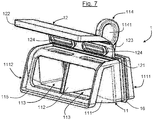
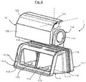
- the cartridge 11 has a central partition 112 extending between the first opening 1111a and the second opening 1112a and defining with the peripheral wall 111 two separate fluid ducts 113.
- the central partition 112 extends projecting from the cartridge 11 along its axis of extension.
- the central partition 112 has an upper part projecting from the cartridge 11 and forming a manipulation tab 114.
- the manipulation tongue 114 has on either side of the central partition 112 two recesses 1141 to allow gripping by a user or installer.
- this manipulation tab 114 makes it easier to insert and remove the cartridge in or out of the siphon 2.
- the second downstream face 1112 has, at the second opening 1112a, a peripheral shoulder 115 in which the valve 12 is received in its closed position.
- This shoulder 115 allows in particular to achieve a good fluid tightness when the valve 12 is in its closed position, thus preventing any fluid passage from the second opening 1112a to the first opening 1111a.
- the non-return block 1 also includes a peripheral seal 116. More specifically, the cartridge 11 has a peripheral groove 117 inside which is housed the peripheral seal 116.
- peripheral seal 116 projects radially outside the cartridge 11 so as to form a protuberance, or a lip, intended to come into contact with the walls of the tube 22 as explained below.
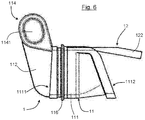
- valve 12 On the figures 3 , 4 and 5 , the valve 12 is shown in its closed position while on the figure 6 , the valve 12 is shown in its passage position.
- the valve 12 is made of a flexible material such as for example an elastomer, and has a substantially bent shape at rest, that is to say that the fixing portion 121 and the sealing portion 122 form between they have a non-zero first angle ⁇ 1 ( figure 8 ).
- the first angle ⁇ 1 formed between the fixing portion 121 and the shutter portion 122, has a value less than 10 ° with respect to a second angle ⁇ 2 measured on the cartridge 11 between an upper face of the peripheral wall 111 and the second downstream face 1112 ( figure 5 ).
- the natural position that it adopts is its position for closing the second opening 1112a.
- the valve 12 when the valve 12 is mounted on the cartridge 11, it is prestressed in its closed position so as to be housed in the peripheral shoulder 115 to prevent the rise of bad odors.
- the value of the prestress is therefore 10 °, thanks to the first angle ⁇ 1 of the valve 12 which is 10 ° less than the second angle ⁇ 2 of the cartridge 11.
- the valve 12 has, in its fixing portion 121, at least one lug 124, and more precisely two lugs 124 intended to be housed in slots 118 formed on the peripheral wall 111 of the cartridge 11 rigid. More specifically, the two slots 118 of the rigid cartridge 11 are formed on a part of the upper wall of the cartridge 11 on either side of the central partition 112.
- the lugs 124 and the slots 118 have an oblong shape so as to cover a surface extending between the central partition 112 and the side walls of the rigid cartridge 11.
- the shutter portion 122 of the valve 12 may have grooves or projections forming stiffening reinforcements to prevent in particular that the shutter portion 122 does not twist, which could reduce its ability to block the return of bad odors. .
- the forces exerted by air coming from the pipe can tend to take off from the cartridge 11 the angles of the shutter portion 122. Therefore, the closure of the second opening 1112a is no longer ensured and bad odors can rise.
- the presence of the grooves or projections on the shutter portion 122 makes it possible to limit or even eliminate this deformation effect due to the forces of the air coming from the pipe.
- valve 12 is independent of the cartridge 11 and is assembled thereon by insertion of the lugs 124 inside the openings 118 of the cartridge 11.
- valve 12 is in one piece with a part of the cartridge 11, for example the peripheral seal 116.
- valve 12 could be attached in a non-removable manner to the cartridge 11, for example by overmolding.
- the user grasps the manipulation tab 114 and then inserts the second face 1112 downstream of the non-return block 1 into the siphon 2, in particular by sliding the lower edge of the second face 1112 downstream onto the ramp 211 of commitment.
- the user continues his movement until the cartridge 11, and in particular the lower part of the cartridge 11, slides completely on the engagement ramp 211, and until the non-return block 1 is inserted into the tube 22 of the siphon 2.
- the peripheral seal 116 is then compressed between the peripheral wall 111 of the cartridge and the partitions of the tube 22.
- the withdrawal of the non-return block 1, in particular for maintenance or cleaning operations, is carried out by gripping the manipulation tongue 114 then carrying out a traction force of the non-return block 1 along the ramp 211 d 'commitment.
- the non-return block 1 can be reinstalled in the siphon 2 as explained above.
- the water In use, when the water must be drained from the shower tray, the water passes through the drain hole of the shower tray and then goes towards the body 21 of the siphon 2 taking the form of the funnel 212 to be guided up to at block 1 non-return.
- the force exerted by the water pushes the valve 12 in its passage position and allows water to be evacuated through the tube 22 towards the pipeline.
- the valve 12 When all the water has drained from the shower tray, the valve 12 covers its closed position in which the closed portion 122 is housed in the peripheral shoulder 115 of the rigid cartridge 11.
- the valve 12 covers its closed position thanks in particular to its shape as well as to its hinge 123, and in particular to the angle between the fixing portion 121 and the shutter portion 122.
- the central partition 112 makes it possible to retain, for example, long hair so as to avoid fouling of the pipes and the formation of plugs due to this fouling.
- the presence of long hair extending through the second opening 1112a may, in the long term, hinder or even prevent the valve 12 from recovering its closed position effectively.
- air carrying unpleasant odors can flow between the valve 12 and the rigid cartridge 11 to reach the first opening 1111a and therefore spread in the shower tray and in the bathroom or the bathroom.
- the ease of assembly and disassembly of the non-return block 1 in the siphon in particular by gripping the manipulation tongue 114, makes it possible to remove the non-return block 1 so as to be able to manually remove the stuck hair. and on the other side of the central partition 112.
- the cleaning operation simply replace the non-return block 1 in the siphon 2 so that the ascent of bad odors is interrupted.
- the simplicity of design of the non-return block 1 allows the parts to be produced independently or commonly from one another in a simple and rapid manner.
- the shape of the valve 12, and in particular its preload allows that in the absence of pressure exerted by the water, the valve 12 recovers its closed position preventing the rise of bad odors.
- the presence of the peripheral seal 116 on the outer periphery of the cartridge 11 also makes it possible to prevent the rise of bad odors but also the fouling around the cartridge 11, that is to say between the cartridge 11 and the walls of the tube 22, so as to retain an insertion and above all an easy removal of the cartridge 11 from the siphon 2.
- the funnel shape 212 and the ramp 211 for engaging the body 21 of the siphon 2 allow both simple engagement and rapid withdrawal of the non-return block 1 but also good water guidance to facilitate the drainage and drainage of water from the shower tray.
Landscapes
- Engineering & Computer Science (AREA)
- Life Sciences & Earth Sciences (AREA)
- Hydrology & Water Resources (AREA)
- Public Health (AREA)
- Water Supply & Treatment (AREA)
- Health & Medical Sciences (AREA)
- General Engineering & Computer Science (AREA)
- Environmental & Geological Engineering (AREA)
- Mechanical Engineering (AREA)
- Bathtubs, Showers, And Their Attachments (AREA)
- Sink And Installation For Waste Water (AREA)
- Nozzles (AREA)
- Domestic Plumbing Installations (AREA)
Applications Claiming Priority (1)
| Application Number | Priority Date | Filing Date | Title |
|---|---|---|---|
| FR1872481A FR3089532B1 (fr) | 2018-12-07 | 2018-12-07 | Bloc anti-retour pour siphon de bac de douche et siphon équipé d’un tel bloc anti-retour |
Publications (3)
| Publication Number | Publication Date |
|---|---|
| EP3663472A1 true EP3663472A1 (de) | 2020-06-10 |
| EP3663472B1 EP3663472B1 (de) | 2023-10-18 |
| EP3663472C0 EP3663472C0 (de) | 2023-10-18 |
Family
ID=67001855
Family Applications (1)
| Application Number | Title | Priority Date | Filing Date |
|---|---|---|---|
| EP19214019.2A Active EP3663472B1 (de) | 2018-12-07 | 2019-12-06 | Rücklaufsperre für siphon einer duschwanne, und siphon, der mit einer solchen rücklaufsperre ausgestattet ist |
Country Status (5)
| Country | Link |
|---|---|
| EP (1) | EP3663472B1 (de) |
| CN (1) | CN111287308B (de) |
| ES (1) | ES2968543T3 (de) |
| FR (1) | FR3089532B1 (de) |
| PL (1) | PL3663472T3 (de) |
Citations (3)
| Publication number | Priority date | Publication date | Assignee | Title |
|---|---|---|---|---|
| GB2449364A (en) * | 2007-05-17 | 2008-11-19 | Phs Group Plc | Waste Outlet for a Urinal |
| KR20120132024A (ko) * | 2011-05-27 | 2012-12-05 | 김기성 | 배수 트랩 |
| US20140373931A1 (en) * | 2013-06-24 | 2014-12-25 | Kevin Huber | Drain valve |
Family Cites Families (8)
| Publication number | Priority date | Publication date | Assignee | Title |
|---|---|---|---|---|
| IT1394289B1 (it) * | 2009-03-05 | 2012-06-06 | Valsir Spa | Dispositivo di scarico d'acqua con sifone, in particolare per docce a pavimento e piatti doccia |
| CN102720252A (zh) * | 2012-07-12 | 2012-10-10 | 苏州沃特节水产品有限公司 | 一种超低结构的同层排水装置 |
| CN202672325U (zh) * | 2012-07-12 | 2013-01-16 | 苏州沃特节水产品有限公司 | 一种超低结构的同层排水装置 |
| CN202936864U (zh) * | 2012-11-22 | 2013-05-15 | 台州市雅妮莎洁具有限公司 | 一种卫生地漏 |
| CN203729394U (zh) * | 2013-09-24 | 2014-07-23 | 浙江健龙卫浴有限公司 | 一种地漏 |
| DE202014007392U1 (de) * | 2014-09-10 | 2014-12-17 | Geberit International Ag | Wasserablauf mit Mehrfachsiphon-Geruchsverschluss |
| CN205100353U (zh) * | 2015-11-02 | 2016-03-23 | 新疆台亚塑胶有限公司 | 一种安装和清洗便捷的防臭地漏 |
| CN205557787U (zh) * | 2016-04-14 | 2016-09-07 | 昆明群之英科技有限公司 | 一种建筑不降板同层排水地漏 |
-
2018
- 2018-12-07 FR FR1872481A patent/FR3089532B1/fr active Active
-
2019
- 2019-12-06 ES ES19214019T patent/ES2968543T3/es active Active
- 2019-12-06 PL PL19214019.2T patent/PL3663472T3/pl unknown
- 2019-12-06 EP EP19214019.2A patent/EP3663472B1/de active Active
- 2019-12-09 CN CN201911250205.4A patent/CN111287308B/zh active Active
Patent Citations (3)
| Publication number | Priority date | Publication date | Assignee | Title |
|---|---|---|---|---|
| GB2449364A (en) * | 2007-05-17 | 2008-11-19 | Phs Group Plc | Waste Outlet for a Urinal |
| KR20120132024A (ko) * | 2011-05-27 | 2012-12-05 | 김기성 | 배수 트랩 |
| US20140373931A1 (en) * | 2013-06-24 | 2014-12-25 | Kevin Huber | Drain valve |
Also Published As
| Publication number | Publication date |
|---|---|
| EP3663472B1 (de) | 2023-10-18 |
| ES2968543T3 (es) | 2024-05-10 |
| CN111287308B (zh) | 2021-11-12 |
| EP3663472C0 (de) | 2023-10-18 |
| CN111287308A (zh) | 2020-06-16 |
| FR3089532A1 (fr) | 2020-06-12 |
| PL3663472T3 (pl) | 2024-02-19 |
| FR3089532B1 (fr) | 2021-04-16 |
Similar Documents
| Publication | Publication Date | Title |
|---|---|---|
| EP1006308B1 (de) | Sicherheitsschnellkupplung für die lösbare Verbindung von Rohrleitungen | |
| EP2088358B1 (de) | Verbindungssteckerelement und Schnellverbindung, die ein solches Element beinhaltet | |
| CA2599060C (fr) | Raccord rapide pour la jonction de deux canalisations d'acheminement d'un gaz sous pression | |
| EP1563147B1 (de) | Vorrichtung zur verbindung von verschleissteilen mit aufnahmewerkzeugen einer baumaschine | |
| WO2007031643A1 (fr) | Raccord rapide de securite pour la jonction de deux canalisations | |
| FR2981722A1 (fr) | Dispositif support de positionnement pour cables le long de conduits de type pipeline immerges | |
| FR2995654A1 (fr) | Prise de raccordement comprenant un corps monobloc logeant un clapet de maintenance et un clapet principal | |
| EP3663472B1 (de) | Rücklaufsperre für siphon einer duschwanne, und siphon, der mit einer solchen rücklaufsperre ausgestattet ist | |
| FR2679622A1 (fr) | Garniture d'etancheite composite pour assemblage verrouille de tuyaux, et assemblage verrouille correspondant. | |
| EP3708899A1 (de) | Hahn, unter druck stehender fluid-behälter und verfahren zum füllen und entnehmen | |
| EP3194818B1 (de) | Verbindungssystem mit einem schliesselement für tauchregler | |
| BE1018968A3 (fr) | Ensemble d'un couvercle et d'un organe de liaison destine a faire partie d'un pistolet a fluide. | |
| EP2543781A1 (de) | Geruchsneutralisierende Manschette für Flüssigkeitsabflussrohrende, und entsprechende Anlage | |
| EP3686359B1 (de) | Siphon mit sperrwasserhöhe, der einen luftdurchlass aufweist, und mit einem solchen siphon ausgestattete sanitärausstattung | |
| EP4183944B1 (de) | Vorrichtung zum befüllen eines spülkastens | |
| EP2431641B1 (de) | Befestigungsvorrichtung für einen Anschluss eines fluidführenden Rohres an einer Hohlwand | |
| WO2016030636A9 (fr) | Dispositif d'aspiration d'effluents gazeux provenant d'une cuve de production industrielle d'aluminium par electrolyse ignée | |
| EP3945167A1 (de) | Anschluss für wasserabflussrohr | |
| EP4217547B1 (de) | Haltevorrichtung | |
| CA2495995C (fr) | Element male ou femelle de raccord rapide et raccord rapide comprenant un tel element | |
| WO2003066361A1 (fr) | Tete de tubulure de remplissage de reservoir de carburant. | |
| FR2916389A1 (fr) | Dispositif de securite pour conduit de remplissage de carburant pour vehicule automobile. | |
| FR3087210A1 (fr) | Dispositif d'obturation d'un orifice d'evacuation d'un reservoir de chasse d'eau | |
| EP2239379B1 (de) | Schutzvorrichtung gegen die Verschmutzung durch Wasserrücklauf | |
| FR2865749A1 (fr) | Reducteur de debit silencieux pour robinet flotteur |
Legal Events
| Date | Code | Title | Description |
|---|---|---|---|
| PUAI | Public reference made under article 153(3) epc to a published international application that has entered the european phase |
Free format text: ORIGINAL CODE: 0009012 |
|
| STAA | Information on the status of an ep patent application or granted ep patent |
Free format text: STATUS: THE APPLICATION HAS BEEN PUBLISHED |
|
| AK | Designated contracting states |
Kind code of ref document: A1 Designated state(s): AL AT BE BG CH CY CZ DE DK EE ES FI FR GB GR HR HU IE IS IT LI LT LU LV MC MK MT NL NO PL PT RO RS SE SI SK SM TR |
|
| AX | Request for extension of the european patent |
Extension state: BA ME |
|
| STAA | Information on the status of an ep patent application or granted ep patent |
Free format text: STATUS: REQUEST FOR EXAMINATION WAS MADE |
|
| 17P | Request for examination filed |
Effective date: 20201204 |
|
| RBV | Designated contracting states (corrected) |
Designated state(s): AL AT BE BG CH CY CZ DE DK EE ES FI FR GB GR HR HU IE IS IT LI LT LU LV MC MK MT NL NO PL PT RO RS SE SI SK SM TR |
|
| STAA | Information on the status of an ep patent application or granted ep patent |
Free format text: STATUS: EXAMINATION IS IN PROGRESS |
|
| 17Q | First examination report despatched |
Effective date: 20220408 |
|
| GRAP | Despatch of communication of intention to grant a patent |
Free format text: ORIGINAL CODE: EPIDOSNIGR1 |
|
| STAA | Information on the status of an ep patent application or granted ep patent |
Free format text: STATUS: GRANT OF PATENT IS INTENDED |
|
| INTG | Intention to grant announced |
Effective date: 20230717 |
|
| GRAS | Grant fee paid |
Free format text: ORIGINAL CODE: EPIDOSNIGR3 |
|
| GRAA | (expected) grant |
Free format text: ORIGINAL CODE: 0009210 |
|
| STAA | Information on the status of an ep patent application or granted ep patent |
Free format text: STATUS: THE PATENT HAS BEEN GRANTED |
|
| AK | Designated contracting states |
Kind code of ref document: B1 Designated state(s): AL AT BE BG CH CY CZ DE DK EE ES FI FR GB GR HR HU IE IS IT LI LT LU LV MC MK MT NL NO PL PT RO RS SE SI SK SM TR |
|
| REG | Reference to a national code |
Ref country code: GB Ref legal event code: FG4D Free format text: NOT ENGLISH |
|
| REG | Reference to a national code |
Ref country code: CH Ref legal event code: EP |
|
| REG | Reference to a national code |
Ref country code: DE Ref legal event code: R096 Ref document number: 602019039508 Country of ref document: DE |
|
| REG | Reference to a national code |
Ref country code: IE Ref legal event code: FG4D Free format text: LANGUAGE OF EP DOCUMENT: FRENCH |
|
| U01 | Request for unitary effect filed |
Effective date: 20231018 |
|
| U07 | Unitary effect registered |
Designated state(s): AT BE BG DE DK EE FI FR IT LT LU LV MT NL PT SE SI Effective date: 20231026 |
|
| U20 | Renewal fee for the european patent with unitary effect paid |
Year of fee payment: 5 Effective date: 20231205 |
|
| PG25 | Lapsed in a contracting state [announced via postgrant information from national office to epo] |
Ref country code: GR Free format text: LAPSE BECAUSE OF FAILURE TO SUBMIT A TRANSLATION OF THE DESCRIPTION OR TO PAY THE FEE WITHIN THE PRESCRIBED TIME-LIMIT Effective date: 20240119 |
|
| PG25 | Lapsed in a contracting state [announced via postgrant information from national office to epo] |
Ref country code: IS Free format text: LAPSE BECAUSE OF FAILURE TO SUBMIT A TRANSLATION OF THE DESCRIPTION OR TO PAY THE FEE WITHIN THE PRESCRIBED TIME-LIMIT Effective date: 20240218 |
|
| PG25 | Lapsed in a contracting state [announced via postgrant information from national office to epo] |
Ref country code: IS Free format text: LAPSE BECAUSE OF FAILURE TO SUBMIT A TRANSLATION OF THE DESCRIPTION OR TO PAY THE FEE WITHIN THE PRESCRIBED TIME-LIMIT Effective date: 20240218 Ref country code: GR Free format text: LAPSE BECAUSE OF FAILURE TO SUBMIT A TRANSLATION OF THE DESCRIPTION OR TO PAY THE FEE WITHIN THE PRESCRIBED TIME-LIMIT Effective date: 20240119 |
|
| REG | Reference to a national code |
Ref country code: ES Ref legal event code: FG2A Ref document number: 2968543 Country of ref document: ES Kind code of ref document: T3 Effective date: 20240510 |
|
| PG25 | Lapsed in a contracting state [announced via postgrant information from national office to epo] |
Ref country code: RS Free format text: LAPSE BECAUSE OF FAILURE TO SUBMIT A TRANSLATION OF THE DESCRIPTION OR TO PAY THE FEE WITHIN THE PRESCRIBED TIME-LIMIT Effective date: 20231018 Ref country code: NO Free format text: LAPSE BECAUSE OF FAILURE TO SUBMIT A TRANSLATION OF THE DESCRIPTION OR TO PAY THE FEE WITHIN THE PRESCRIBED TIME-LIMIT Effective date: 20240118 Ref country code: HR Free format text: LAPSE BECAUSE OF FAILURE TO SUBMIT A TRANSLATION OF THE DESCRIPTION OR TO PAY THE FEE WITHIN THE PRESCRIBED TIME-LIMIT Effective date: 20231018 |
|
| REG | Reference to a national code |
Ref country code: DE Ref legal event code: R097 Ref document number: 602019039508 Country of ref document: DE |
|
| PG25 | Lapsed in a contracting state [announced via postgrant information from national office to epo] |
Ref country code: CZ Free format text: LAPSE BECAUSE OF FAILURE TO SUBMIT A TRANSLATION OF THE DESCRIPTION OR TO PAY THE FEE WITHIN THE PRESCRIBED TIME-LIMIT Effective date: 20231018 |
|
| PG25 | Lapsed in a contracting state [announced via postgrant information from national office to epo] |
Ref country code: SK Free format text: LAPSE BECAUSE OF FAILURE TO SUBMIT A TRANSLATION OF THE DESCRIPTION OR TO PAY THE FEE WITHIN THE PRESCRIBED TIME-LIMIT Effective date: 20231018 |
|
| PG25 | Lapsed in a contracting state [announced via postgrant information from national office to epo] |
Ref country code: SM Free format text: LAPSE BECAUSE OF FAILURE TO SUBMIT A TRANSLATION OF THE DESCRIPTION OR TO PAY THE FEE WITHIN THE PRESCRIBED TIME-LIMIT Effective date: 20231018 Ref country code: SK Free format text: LAPSE BECAUSE OF FAILURE TO SUBMIT A TRANSLATION OF THE DESCRIPTION OR TO PAY THE FEE WITHIN THE PRESCRIBED TIME-LIMIT Effective date: 20231018 Ref country code: CZ Free format text: LAPSE BECAUSE OF FAILURE TO SUBMIT A TRANSLATION OF THE DESCRIPTION OR TO PAY THE FEE WITHIN THE PRESCRIBED TIME-LIMIT Effective date: 20231018 |
|
| REG | Reference to a national code |
Ref country code: CH Ref legal event code: PL |
|
| PLBE | No opposition filed within time limit |
Free format text: ORIGINAL CODE: 0009261 |
|
| STAA | Information on the status of an ep patent application or granted ep patent |
Free format text: STATUS: NO OPPOSITION FILED WITHIN TIME LIMIT |
|
| PG25 | Lapsed in a contracting state [announced via postgrant information from national office to epo] |
Ref country code: MC Free format text: LAPSE BECAUSE OF FAILURE TO SUBMIT A TRANSLATION OF THE DESCRIPTION OR TO PAY THE FEE WITHIN THE PRESCRIBED TIME-LIMIT Effective date: 20231018 |
|
| PG25 | Lapsed in a contracting state [announced via postgrant information from national office to epo] |
Ref country code: MC Free format text: LAPSE BECAUSE OF FAILURE TO SUBMIT A TRANSLATION OF THE DESCRIPTION OR TO PAY THE FEE WITHIN THE PRESCRIBED TIME-LIMIT Effective date: 20231018 |
|
| 26N | No opposition filed |
Effective date: 20240719 |
|
| REG | Reference to a national code |
Ref country code: IE Ref legal event code: MM4A |
|
| PG25 | Lapsed in a contracting state [announced via postgrant information from national office to epo] |
Ref country code: IE Free format text: LAPSE BECAUSE OF NON-PAYMENT OF DUE FEES Effective date: 20231206 |
|
| PG25 | Lapsed in a contracting state [announced via postgrant information from national office to epo] |
Ref country code: CH Free format text: LAPSE BECAUSE OF NON-PAYMENT OF DUE FEES Effective date: 20231231 |
|
| PG25 | Lapsed in a contracting state [announced via postgrant information from national office to epo] |
Ref country code: IE Free format text: LAPSE BECAUSE OF NON-PAYMENT OF DUE FEES Effective date: 20231206 Ref country code: CH Free format text: LAPSE BECAUSE OF NON-PAYMENT OF DUE FEES Effective date: 20231231 |
|
| U20 | Renewal fee for the european patent with unitary effect paid |
Year of fee payment: 6 Effective date: 20241202 |
|
| PG25 | Lapsed in a contracting state [announced via postgrant information from national office to epo] |
Ref country code: CY Free format text: LAPSE BECAUSE OF FAILURE TO SUBMIT A TRANSLATION OF THE DESCRIPTION OR TO PAY THE FEE WITHIN THE PRESCRIBED TIME-LIMIT; INVALID AB INITIO Effective date: 20191206 |
|
| PG25 | Lapsed in a contracting state [announced via postgrant information from national office to epo] |
Ref country code: HU Free format text: LAPSE BECAUSE OF FAILURE TO SUBMIT A TRANSLATION OF THE DESCRIPTION OR TO PAY THE FEE WITHIN THE PRESCRIBED TIME-LIMIT; INVALID AB INITIO Effective date: 20191206 |
|
| PG25 | Lapsed in a contracting state [announced via postgrant information from national office to epo] |
Ref country code: TR Free format text: LAPSE BECAUSE OF FAILURE TO SUBMIT A TRANSLATION OF THE DESCRIPTION OR TO PAY THE FEE WITHIN THE PRESCRIBED TIME-LIMIT Effective date: 20231018 |
|
| PGFP | Annual fee paid to national office [announced via postgrant information from national office to epo] |
Ref country code: GB Payment date: 20251208 Year of fee payment: 7 |
|
| U20 | Renewal fee for the european patent with unitary effect paid |
Year of fee payment: 7 Effective date: 20251208 |
|
| PGFP | Annual fee paid to national office [announced via postgrant information from national office to epo] |
Ref country code: PL Payment date: 20251205 Year of fee payment: 7 |
|
| PGFP | Annual fee paid to national office [announced via postgrant information from national office to epo] |
Ref country code: RO Payment date: 20251119 Year of fee payment: 7 |
|
| PGFP | Annual fee paid to national office [announced via postgrant information from national office to epo] |
Ref country code: ES Payment date: 20260105 Year of fee payment: 7 |