EP3663472B1 - Bloc anti-retour pour siphon de bac de douche et siphon équipé d'un tel bloc anti-retour - Google Patents
Bloc anti-retour pour siphon de bac de douche et siphon équipé d'un tel bloc anti-retour Download PDFInfo
- Publication number
- EP3663472B1 EP3663472B1 EP19214019.2A EP19214019A EP3663472B1 EP 3663472 B1 EP3663472 B1 EP 3663472B1 EP 19214019 A EP19214019 A EP 19214019A EP 3663472 B1 EP3663472 B1 EP 3663472B1
- Authority
- EP
- European Patent Office
- Prior art keywords
- siphon
- cartridge
- opening
- shower tray
- flap valve
- Prior art date
- Legal status (The legal status is an assumption and is not a legal conclusion. Google has not performed a legal analysis and makes no representation as to the accuracy of the status listed.)
- Active
Links
Images




Classifications
-
- E—FIXED CONSTRUCTIONS
- E03—WATER SUPPLY; SEWERAGE
- E03F—SEWERS; CESSPOOLS
- E03F5/00—Sewerage structures
- E03F5/04—Gullies inlets, road sinks, floor drains with or without odour seals or sediment traps
- E03F5/0407—Floor drains for indoor use
- E03F5/0408—Floor drains for indoor use specially adapted for showers
-
- E—FIXED CONSTRUCTIONS
- E03—WATER SUPPLY; SEWERAGE
- E03F—SEWERS; CESSPOOLS
- E03F5/00—Sewerage structures
- E03F5/20—Siphon pipes or inverted siphons
-
- E—FIXED CONSTRUCTIONS
- E03—WATER SUPPLY; SEWERAGE
- E03C—DOMESTIC PLUMBING INSTALLATIONS FOR FRESH WATER OR WASTE WATER; SINKS
- E03C1/00—Domestic plumbing installations for fresh water or waste water; Sinks
- E03C1/12—Plumbing installations for waste water; Basins or fountains connected thereto; Sinks
- E03C1/28—Odour seals
- E03C1/298—Odour seals consisting only of non-return valve
-
- E—FIXED CONSTRUCTIONS
- E03—WATER SUPPLY; SEWERAGE
- E03F—SEWERS; CESSPOOLS
- E03F5/00—Sewerage structures
- E03F5/04—Gullies inlets, road sinks, floor drains with or without odour seals or sediment traps
-
- E—FIXED CONSTRUCTIONS
- E03—WATER SUPPLY; SEWERAGE
- E03F—SEWERS; CESSPOOLS
- E03F5/00—Sewerage structures
- E03F5/04—Gullies inlets, road sinks, floor drains with or without odour seals or sediment traps
- E03F5/042—Arrangements of means against overflow of water, backing-up from the drain
-
- E—FIXED CONSTRUCTIONS
- E03—WATER SUPPLY; SEWERAGE
- E03F—SEWERS; CESSPOOLS
- E03F5/00—Sewerage structures
- E03F5/04—Gullies inlets, road sinks, floor drains with or without odour seals or sediment traps
- E03F5/06—Gully gratings
-
- E—FIXED CONSTRUCTIONS
- E03—WATER SUPPLY; SEWERAGE
- E03F—SEWERS; CESSPOOLS
- E03F7/00—Other installations or implements for operating sewer systems, e.g. for preventing or indicating stoppage; Emptying cesspools
- E03F7/02—Shut-off devices
-
- F—MECHANICAL ENGINEERING; LIGHTING; HEATING; WEAPONS; BLASTING
- F16—ENGINEERING ELEMENTS AND UNITS; GENERAL MEASURES FOR PRODUCING AND MAINTAINING EFFECTIVE FUNCTIONING OF MACHINES OR INSTALLATIONS; THERMAL INSULATION IN GENERAL
- F16K—VALVES; TAPS; COCKS; ACTUATING-FLOATS; DEVICES FOR VENTING OR AERATING
- F16K15/00—Check valves
- F16K15/14—Check valves with flexible valve members
- F16K15/144—Check valves with flexible valve members the closure elements being fixed along all or a part of their periphery
-
- E—FIXED CONSTRUCTIONS
- E03—WATER SUPPLY; SEWERAGE
- E03F—SEWERS; CESSPOOLS
- E03F5/00—Sewerage structures
- E03F5/04—Gullies inlets, road sinks, floor drains with or without odour seals or sediment traps
- E03F2005/0416—Gullies inlets, road sinks, floor drains with or without odour seals or sediment traps with an odour seal
- E03F2005/0417—Gullies inlets, road sinks, floor drains with or without odour seals or sediment traps with an odour seal in the form of a valve
Definitions
- the field of the invention is that of the design and manufacture of sanitary equipment, hydraulic equipment in general, and in particular equipment for the evacuation of water.
- the invention relates to a siphon for a shower tray, the siphon comprising a non-return block mounted in the siphon to allow the evacuation of water while preventing the rise of bad odors from the pipes when all the water has been drained.
- each membrane comprises a first inclined portion, together forming a sort of funnel, followed by a second straight portion, the straight portions being in contact with one another in the closing position of the pair of membranes.
- the water to be evacuated from the shower tray exerts pressure on the first inclined portions so as to position them substantially straight, that is to say parallel to the second portions, and to allow the evacuation of the water by spacing the two second portions relative to each other.
- the first inclined portions recover their initial position so that the second portions are in contact with each other, thus preventing any rise of water. bad smells from the pipes.
- the membranes when inserting the block into a siphon, the membranes come into contact with the walls of the siphon and can be damaged with the risk of no longer ensuring the sealing and therefore allowing bad odors to come up from the pipes.
- such a block being made of an elastically deformable material, such as an elastomer, it is possible that the block is offset when it is introduced into the siphon.
- the elastically deformable material will then ensure that the block holds in the siphon but will leave spaces between the block and the walls. of the siphon, spaces through which bad odors can rise into the shower tray and therefore into the shower room or bathroom.
- misalignment or poor positioning can cause permanent separation of the membranes, thus allowing bad odors to pass.
- blocks to have manufacturing defects, for example an overgrowth of material.
- growths can for example be due to a core linked to the injection of thermoplastic material.
- the elastically deformable material does not prevent the assembly of the block in the siphon but creates passageways for bad odors.
- Another known non-return block comprises a valve system mounted to pivot relative to the body by means of a hinge.
- a hinge generally comprises an axis (male part) and hooking means (female parts) secured to the valve, the hooking means being intended to be rotatably mounted on the axis.
- This hinge has the major disadvantage of limited watertightness.
- the attachment means attached to the valve are spaced apart from each other to create operating clearance. This operating game thus creates an air passage through which the air coming from the pipes and loaded with bad odors can rush in and rise up to the sanitary equipment.
- the invention aims in particular to overcome the disadvantages of the prior art.
- the invention aims to provide a siphon which ensures blocking of bad odors in all circumstances.
- the invention also aims to provide such a siphon which makes its installation easier and more reliable.
- the invention further aims to provide a siphon block which is easy to remove, in particular for its maintenance.
- a rigid cartridge ensures good positioning of the non-return block in the siphon. Indeed, the rigidity of the cartridge prevents it from deforming when it is inserted into the siphon, such deformation creating the passages allowing the rise of bad odors as in the prior art.
- the rigidity of the cartridge ensures visual control of the correct positioning of the non-return block in the siphon.
- valve cannot be damaged when inserting the non-return block into the siphon since it is rotatably mounted on the cartridge.
- the rigid cartridge which may be caused to rub against the walls of the siphon, the valve thus being preserved from any damage by friction.
- the flexible hinge allows you to change the position of the valve while preserving its lifespan. Indeed, a flexible hinge is more resistant and less subject to stress (in particular friction) than conventional hinges comprising at least one male part and one female part fitted together. The anti-return block then has a good lifespan over time, which gives it ensures that bad odors are permanently blocked in the pipes.
- the flexible hinge ensures the change of position of the valve by an unwinding movement.
- the hinge allows the change of position of the valve thanks to its elasticity, which prevents fatigue for the benefit of its lifespan.
- the manufacturing and maintenance of the anti-return block are simplified. Furthermore, the lifespan of the non-return block is increased compared to a separate valve and hinge, since there is no friction between the valve and the hinge. In addition, the manufacturing costs of such a one-piece valve are reduced while the manufacturing rates can be increased, in particular by molding the one-piece valve.
- handling the block is simplified since a user or installer simply needs to grab the handling tab to insert the block into the siphon, or on the contrary, remove the block from the siphon. .
- the valve comprises a fixing portion having lugs intended to be housed in openings of the cartridge.
- the hinge is pre-stressed so as to force the valve in its closed position in the absence of a fluid coming from the first opening.
- the prestressing of the valve is advantageously ensured by a first angle measured between a fixing portion and a shutter portion, which has a lower value of 10° compared to a second angle measured on the cartridge between an upper face of a peripheral wall and a second downstream face presenting the second opening.
- valve when the valve is mounted on the cartridge, it is preloaded in its closed position so as to seal the second opening to prevent the rise of bad odors.
- the cartridge carries a peripheral seal.
- the peripheral seal makes it possible to create insulation (we also speak of sealing in the field of the trade) between the cartridge of the block and the walls of the siphon. This prevents bad odors from circulating and rising between the block and the siphon walls. In other words, when the valve is in its closed position, no bad odor can go up into the shower tray.
- the second opening has a peripheral shoulder in which the valve is received in its closed position.
- Such a shoulder makes it possible to perfect the sealing of the non-return block.
- the valve When the valve is in its closed position, it is housed in the shoulder, so that when inserting or removing the block into or out of the siphon, the edges of the valve cannot rub against the walls of the siphon. siphon, and therefore deteriorate.
- a siphon helps block the rise of bad odors in the shower tray. Furthermore, a siphon according to the invention can be used in particular in a shower tray having a low height.
- extraction of the anti-return block is also made easier, in particular to allow maintenance of the anti-return block and therefore increase its lifespan.
- the body has a funnel shape to direct the fluid towards the cartridge of the non-return block.
- the subject of the invention is a shower tray having a drain hole to which a siphon as described above is connected.
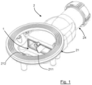
- the siphon 2 can also include a grid 23 intended to at least partially cover the body 21 and to close the drain hole T of the shower tray B while allowing the passage of water to evacuate the water from the tray shower B.
- the passage of water can for example be ensured thanks to perforations or a space provided with the body 21.
- the siphon 2 can also include an interface 24 intended to be positioned between the tube 22 and the pipe.
- the body 21 of the siphon has an engagement ramp 211 allowing, as explained below, the insertion of the anti-return block 1.
- the body 21 has a funnel shape 212 opening onto the engagement ramp 211 and allowing the water to be evacuated to be guided towards the anti-return block 1 and therefore towards the pipe.
- the cartridge 11 is a rigid cartridge, for example made of a thermoplastic material.
- the cartridge 11 has a central partition 112 extending between the first opening 1111a and the second opening 1112a and defining with the peripheral wall 111 two distinct fluidic conduits 113.
- the central partition 112 extends projecting from the cartridge 11 along its axis of extension.
- the central partition 112 has an upper part projecting from the cartridge 11 and forming a handling tab 114.
- the handling tab 114 has on either side of the central partition 112 two recesses 1141 to allow gripping by a user or installer.
- this handling tab 114 makes it easier to insert and remove the cartridge into or out of the siphon 2.
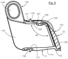
- the second downstream face 1112 has, at the level of the second opening 1112a, a peripheral shoulder 115 in which the valve 12 is received in its closed position.
- This shoulder 115 makes it possible in particular to achieve a good fluid seal when the valve 12 is in its closed position, thus preventing any fluid passage from the second opening 1112a to the first opening 1111a.
- the anti-return block 1 also includes a peripheral seal 116. More precisely, the cartridge 11 has a peripheral groove 117 inside which the peripheral seal 116 is housed.
- peripheral seal 116 projects radially outside the cartridge 11 so as to form a protrusion, or a lip, intended to come into contact with the walls of the tube 22 as explained below.
- valve 12 On the figures 3 , 4 And 5 , the valve 12 is shown in its closed position while on the Figure 6 , the valve 12 is shown in its passage position.
- the valve 12 is made of a flexible material such as for example an elastomer, and has a substantially bent shape at rest, that is to say that the fixing portion 121 and the closing portion 122 form between they have a first non-zero angle ⁇ 1 ( figure 8 ).
- the first angle ⁇ 1 formed between the fixing portion 121 and the shutter portion 122, has a lower value of 10° compared to a second angle ⁇ 2 measured on the cartridge 11 between an upper face of the peripheral wall 111 and the second face 1112 downstream ( figure 5 ).
- the natural position that it adopts is its position of closing the second opening 1112a.
- the valve 12 when the valve 12 is mounted on the cartridge 11, it is pre-stressed in its closed position so as to fit into the peripheral shoulder 115 to prevent the rise of bad odors.
- the value of the preload is therefore 10°, thanks to the first angle ⁇ 1 of the valve 12 which is 10° lower than the second angle ⁇ 2 of the cartridge 11.
- the valve 12 has, in its fixing portion 121, at least one lug 124, and more precisely two lugs 124 intended to be housed in slots 118 made on the peripheral wall 111 of the rigid cartridge 11. More precisely, the two openings 118 of the rigid cartridge 11 are made on a part of the upper wall of the cartridge 11 on either side of the central partition 112.
- the lugs 124 and the slots 118 have an oblong shape so as to cover a surface extending between the central partition 112 and the side walls of the rigid cartridge 11.
- the closing portion 122 of the valve 12 may have grooves or projections forming stiffening reinforcements to prevent the closing portion 122 from twisting, which could reduce its capacity to block the rise of bad odors. .
- the forces exerted by air coming from the pipe can tend to detach the angles of the cartridge 11 from the cartridge 11. shutter portion 122. From then on, the blocking of the second opening 1112a is no longer ensured and bad odors can arise.
- the presence of grooves or projections on the closure portion 122 makes it possible to limit or even eliminate this effect of deformation due to the forces of the air coming from the pipe.
- valve 12 is independent of the cartridge 11 and is assembled thereon by inserting the lugs 124 inside the openings 118 of the cartridge 11.
- valve 12 is in one piece with a part of the cartridge 11, for example the peripheral seal 116.
- valve 12 could be attached in a non-removable manner to the cartridge 11, for example by overmolding.
- the user grasps the handling tab 114 then inserts the second downstream face 1112 of the anti-return block 1 into the siphon 2, in particular by sliding the lower edge of the second downstream face 1112 on the ramp 211 of commitment.
- the user continues his movement until the cartridge 11, and in particular the lower part of the cartridge 11, slides completely on the engagement ramp 211, and until the anti-return block 1 is inserted into the tube 22 of the siphon 2.
- the peripheral seal 116 is then compressed between the peripheral wall 111 of the cartridge and the partitions of the tube 22.
- the removal of the anti-return block 1, in particular for maintenance or cleaning operations, is done by gripping the handling tab 114 then performing a tensile force on the anti-return block 1 along the ramp 211 d 'commitment.
- anti-return block 1 can be reinstalled in siphon 2 as explained previously.
- the water In use, when the water must be drained from the shower tray, the water passes through the drain hole of the shower tray then heads towards the body 21 of the siphon 2 taking the shape of a funnel 212 to be guided until to anti-return block 1.
- the force exerted by the water pushes the valve 12 into its passage position and allows the water to be evacuated through the tube 22 towards the pipe.
- valve 12 When all the water has drained from the shower tray, the valve 12 recovers its closed position in which the closing portion 122 is housed in the peripheral shoulder 115 of the rigid cartridge 11.
- the valve 12 covers its shutter position thanks in particular to its shape as well as to its hinge 123, and particularly to the angle between the fixing portion 121 and the shutter portion 122.
- the central partition 112 makes it possible to retain, for example, long hair so as to avoid clogging of the pipes and the formation of blockages due to this clogging.
- the presence of long hair extending through the second opening 1112a may, ultimately, hinder or even prevent the valve 12 from recovering its closed position effectively. This then results in air carrying bad odors being able to flow between the valve 12 and the rigid cartridge 11 to reach the first opening 1111a and therefore spread into the shower tray and into the bathroom or bathroom. bathroom.
- the ease of assembly and disassembly of the anti-return block 1 in the siphon in particular by gripping the handling tab 114, makes it possible to remove the anti-return block 1 to be able to manually remove the hair stuck on either side. and on the other side of the central partition 112.
- the cleaning operation simply replace the anti-return block 1 in the siphon 2 so that the rise of bad odors is interrupted.
- the simplicity of design of the anti-return block 1 allows the parts to be produced independently or jointly from each other in a simple and rapid manner.
- valve 12 the shape of the valve 12, and in particular its pre-tensioning, allows that in the absence of pressure exerted by the water, the valve 12 covers its closed position preventing the rise of bad odors.
- the presence of the peripheral seal 116 on the outer periphery of the cartridge 11 also makes it possible to prevent the rise of bad odors but also clogging around the cartridge 11, that is to say between the cartridge 11 and the walls of the tube 22, so as to maintain easy insertion and especially removal of the cartridge 11 from the siphon 2.
- the funnel shape 212 and the ramp 211 for engaging the body 21 of the siphon 2 allow both simple engagement and rapid removal of the anti-return block 1 but also good guidance of the water to facilitate the water flow and evacuation of water out of the shower tray.
Landscapes
- Engineering & Computer Science (AREA)
- Life Sciences & Earth Sciences (AREA)
- Hydrology & Water Resources (AREA)
- Public Health (AREA)
- Water Supply & Treatment (AREA)
- Health & Medical Sciences (AREA)
- General Engineering & Computer Science (AREA)
- Environmental & Geological Engineering (AREA)
- Mechanical Engineering (AREA)
- Bathtubs, Showers, And Their Attachments (AREA)
- Sink And Installation For Waste Water (AREA)
- Nozzles (AREA)
- Domestic Plumbing Installations (AREA)
Description
- Le domaine de l'invention est celui de la conception et de la fabrication d'équipements sanitaires, hydrauliques en général, et en particulier d'équipements pour l'évacuation d'eau.
- Plus précisément, l'invention concerne un siphon pour bac de douche, le siphon comprenant un bloc anti-retour monté dans le siphon pour permettre l'évacuation de l'eau tout en empêchant la remontée de mauvaises odeurs depuis les canalisations lorsque toute l'eau a été évacuée.
- On connait de tels blocs qui comprennent une paire de membranes mobiles entre une position de passage dans laquelle les membranes sont écartées l'une de l'autre pour autoriser une évacuation d'eau, et une position d'obturation dans laquelle les membranes sont au contact l'une de l'autre pour empêcher la remontée de mauvaises odeurs depuis les canalisations.
- Plus particulièrement, chaque membrane comprend une première portion inclinée, formant ensemble une sorte d'entonnoir, suivie d'une deuxième portion droite, les portions droites étant au contact l'une de l'autre dans la position d'obturation de la paire de membranes.
- L'eau à évacuer du bac de douche exerce une pression sur les premières portions inclinées de sorte à les positionner sensiblement droites, c'est-à-dire parallèles aux deuxièmes portions, et à autoriser l'évacuation de l'eau par écartement des deux deuxièmes portions l'une par rapport à l'autre.
- En l'absence d'eau à évacuer, et donc de la force qu'elle exerce, les premières portions inclinées recouvrent leur position initiale de sorte que les deuxièmes portions soient au contact l'une de l'autre, empêchant ainsi toute remontée de mauvaises odeurs depuis les canalisations.
- Si un tel bloc anti-retour donne satisfaction, il n'est pas sans inconvénient.
- En effet, lors de l'insertion du bloc dans un siphon, les membranes viennent au contact des parois du siphon et peuvent s'abîmer au risque de ne plus assurer l'obturation et donc de laisser les mauvaises odeurs remonter des canalisations.
- Par ailleurs, un tel bloc étant réalisé dans un matériau élastiquement déformable, tel qu'un élastomère, il est possible que le bloc soit désaxé lorsqu'il est introduit dans le siphon. Le matériau élastiquement déformable assurera alors une tenue du bloc dans le siphon mais laissera des espaces entre le bloc et les parois
du siphon, espaces par lesquels les mauvaises odeurs peuvent remonter dans le bac de douche et donc dans la salle d'eau ou salle de bain. - En outre, un désaxement ou mauvais positionnement peut engendrer un écartement permanent des membranes, laissant ainsi passer les mauvaises odeurs.
- Enfin, il est fréquent que des blocs présentent des défauts de fabrication, par exemple une excroissance de matière. De telles excroissances peuvent par exemple être dues à une carotte liée à l'injection de matière thermoplastique.
- Toutefois, le matériau élastiquement déformable n'empêche pas le montage du bloc dans le siphon mais crée des voies de passage pour les mauvaises odeurs.
- Un autre bloc anti-retour connu comprend un système de clapet monté pivotant par rapport au corps au moyen d'une charnière. Une telle charnière comprend généralement un axe (pièce mâle) et des moyens d'accroche (pièces femelles) solidaires du clapet, les moyens d'accroche étant destinés à être montés à rotation sur l'axe.
- Cette charnière présente comme inconvénient majeur une étanchéité limitée. En effet, les moyens d'accroche solidaires du clapet sont écartés les uns des autres pour créer un jeu de fonctionnement. Ce jeu de fonctionnement crée ainsi un passage d'air par lequel l'air provenant des canalisations et chargé de mauvaises odeurs peut s'engouffrer et remonter jusque dans l'équipement sanitaire.
- Il est également connu de l'art antérieur concernant le domaine technique des équipements sanitaires les documents de brevets publiés sous les numéros
US 2014/373931 ,GB 2 449 364 KR 2012 013 202 - L'invention a notamment pour objectif de palier les inconvénients de l'art antérieur.
- Plus précisément, l'invention a pour objectif de proposer un siphon qui assure un blocage des mauvaises odeurs en toutes circonstances.
- L'invention a également pour objectif de fournir un tel siphon qui facilite et fiabilise son installation.
- L'invention a en outre pour objectif de fournir un siphon le bloc duquel soit simple de retrait, notamment pour sa maintenance.
- Ces objectifs, ainsi que d'autres qui apparaîtront par la suite, sont atteints grâce à l'invention qui a pour objet un siphon selon les termes de la revendication 1.
- L'utilisation d'une cartouche rigide assure un bon positionnement du bloc anti-retour dans le siphon. En effet, la rigidité de la cartouche évite que celle-ci ne se déforme lors de son insertion dans le siphon, une telle déformation créant les passages permettant la remontée de mauvaises odeurs comme dans l'art antérieur.
- Par ailleurs, la rigidité de la cartouche permet d'assurer un contrôle visuel du bon positionnement du bloc anti-retour dans le siphon.
- Enfin, le clapet ne peut pas être abîmé lors de l'insertion du bloc anti-retour dans le siphon puisqu'il est monté à rotation sur la cartouche. Ainsi, lors de l'insertion du bloc anti-retour dans le siphon, c'est la cartouche rigide qui pourra être amenée à frotter contre les parois du siphon, le clapet étant ainsi préservé de toute dégradation par frottement.
- La charnière souple permet de changer le clapet de position tout en préservant sa durée de vie. En effet, une charnière souple est plus résistante et moins soumises aux efforts (notamment de frottements) que les charnières classiques comprenant au moins une pièce mâle et une pièce femelle emboitées. Le bloc anti-retour présente alors une bonne durée de vie dans le temps ce qui lui permet d'assurer un blocage des mauvaises odeurs dans les canalisations de manière pérenne.
- Par ailleurs, la charnière souple assure le changement de position du clapet par un mouvement de déroulement. En d'autres termes, la charnière permet le changement de position du clapet grâce à son élasticité, ce qui évite sa fatigue au bénéfice de sa durée de vie.
- De plus, la fabrication et la maintenance du bloc anti-retour sont simplifiées. Par ailleurs, la durée de vie du bloc anti-retour est accrue par rapport à un clapet et une charnière dissociés, puisqu'il n'existe pas de frottements entre le clapet et la charnière. En outre, les coûts de fabrication d'un tel clapet monobloc sont réduits tandis que les cadences de fabrication peuvent être augmentées, notamment en réalisant un moulage du clapet monobloc.
- Enfin, la manipulation du bloc est simplifiée puisqu'il suffit simplement à un utilisateur ou un installateur de se saisir de la languette de manipulation pour réaliser l'insertion du bloc dans le siphon, ou au contraire, réaliser le retrait du bloc hors du siphon.
- Selon un mode de réalisation préférentiel, le clapet comprend une portion de fixation présentant des ergots destinés à se loger dans des lumières de la cartouche.
- La solidarisation du clapet sur la cartouche est ainsi simplifiée. De plus, un tel montage est réversible, ce qui permet d'assurer une maintenance efficace du bloc anti-retour.
- Avantageusement, la charnière est précontrainte de sorte à contraindre le clapet dans sa position d'obturation en l'absence d'un fluide provenant de la première ouverture.
- On s'assure ainsi du blocage des mauvaises odeurs dans les canalisations en l'absence d'eau à évacuer du bac de douche. En effet, lorsqu'il n'y a pas d'eau à évacuer, aucune pression ne s'exerce sur le clapet pour le positionner dans sa position de passage. La précontrainte de la charnière permet donc d'éviter que le clapet ne se bloque en position de passage, ce qui faciliterait alors les remontées de mauvaises odeurs.
- Dans ce cas, la précontrainte du clapet est avantageusement assurée par un premier angle mesuré entre une portion de fixation et une portion d'obturation, qui présente une valeur inférieure de 10° par rapport à un deuxième angle mesuré sur
la cartouche entre une face supérieure d'une paroi périphérique et une deuxième face aval présentant la deuxième ouverture. - Grâce à cette valeur de précontrainte, lorsque le clapet est monté sur la cartouche, il est précontraint dans sa position d'obturation de sorte à obturer de manière étanche la deuxième ouverture pour empêcher la remontée des mauvaises odeurs.
- Selon un mode préféré de réalisation, la cartouche porte un joint périphérique.
- Le joint périphérique permet de réaliser une isolation (on parle également d'étancher dans le domaine du métier) entre la cartouche du bloc et les parois du siphon. Ainsi, les mauvaises odeurs ne peuvent pas circuler et remonter entre le bloc et les parois du siphon. En d'autres termes, lorsque le clapet est dans sa position d'obturation, aucune mauvaise odeur ne peut remonter jusque dans le bac de douche.
- Avantageusement, la deuxième ouverture présente un épaulement périphérique dans lequel est reçu le clapet dans sa position d'obturation.
- Un tel épaulement permet de parfaire l'étanchéité du bloc anti-retour. Lorsque le clapet est dans sa position d'obturation, il est logé dans l'épaulement, si bien que lors de l'insertion ou du retrait du bloc dans ou hors du siphon, les bords du clapet ne peuvent pas frotter contre les parois du siphon, et donc se dégrader.
- Un tel siphon permet de bloquer la remontée de mauvaises odeurs dans le bac de douche. Par ailleurs, un siphon selon l'invention est notamment utilisable dans un bac de douche présentant une faible hauteur.
- De plus, l'insertion du bloc anti-retour est facilitée puisqu'il suffit de faire glisser le bloc sur la rampe d'engagement.
- De même l'extraction du bloc anti-retour est également facilitée, notamment pour permettre la maintenance du bloc anti-retour et donc augmenter sa durée de vie.
- Avantageusement, le corps présente forme en entonnoir pour diriger le fluide vers la cartouche du bloc anti-retour.
- L'évacuation de l'eau est ainsi facilitée puisque l'eau est guidée vers le bloc anti-retour.
- L'invention a enfin pour objet un bac de douche présentant un trou d'évacuation auquel est raccordé un siphon tel que décrit précédemment.
- D'autres caractéristiques et avantages de l'invention apparaîtront plus clairement à la lecture de la description suivante d'un mode de réalisation préférentiel de l'invention, donné à titre d'exemple illustratif et non limitatif, et des dessins annexés parmi lesquels :
- la
figure 1 est une vue en perspective de dessus montrant un siphon selon l'invention à l'intérieur duquel est inséré un bloc anti-retour; - la
figure 2 est une vue de côté montrant l'insertion d'un bloc anti-retour dans un siphon selon l'invention; - la
figure 3 est une vue en perspective avant de dessus d'un bloc anti-retour pour bac de douche, - la
figure 4 est une vue en perspective arrière de dessus d'un bloc anti-retour pour bac de douche, - la
figure 5 est une vue en coupe transversale d'un bloc anti-retour pour bac de douche, selon une première forme de réalisation, le bloc étant illustré dans une position de blocage ; - la
figure 6 est une vue de côté d'un bloc anti-retour pour bac de douche, le bloc étant illustré dans une position de passage ; - la
figure 7 est une vue en perspective avant de dessus d'un bloc anti-retour pour bac de douche, selon une deuxième forme de réalisation, le bloc étant illustré dans une position de blocage, - la
figure 8 est une vue éclatée d'un bloc anti-retour pour bac de douche, selon la première forme de réalisation. - Tel qu'illustré sur les
figures 1 et2 , un bloc 1 anti retour selon l'invention est monté dans un siphon 2 d'un équipement sanitaire illustré schématiquement sur lafigure 2 , tel qu'un bac B de douche présentant un trou T d'évacuation. Le siphon 2 comprend : - un corps 21 destiné à être logé dans le trou T d'évacuation du bac B de douche ;
- un tube 22 prolongeant le corps 21 jusqu'à une canalisation d'évacuation des eaux usées (non illustrée).
- Eventuellement, le siphon 2 peut également comprendre une grille 23 destinée à recouvrir au moins partiellement le corps 21 et à fermer le trou T d'évacuation du bac B de douche tout en autorisant le passage de l'eau pour évacuer l'eau du bac B de douche. Le passage de l'eau peut par exemple être assuré grâce à des perforations ou à un espace ménagé avec le corps 21.
- Pour s'adapter à différents diamètres de canalisations, le siphon 2 peut en outre comprendre une interface 24 destinée à être positionnée entre le tube 22 et la canalisation.
- En référence à la
figure 1 , le corps 21 du siphon présente une rampe 211 d'engagement permettant, comme expliqué ci-après, l'insertion du bloc 1 anti-retour. - En outre, le corps 21 présente une forme 212 d'entonnoir débouchant sur la rampe 211 d'engagement et permettant un guidage de l'eau à évacuer vers le bloc 1 anti-retour et donc vers la canalisation.
- En référence aux
figures 2 à 8 , le bloc 1 anti-retour selon l'invention comprend : - une cartouche 11 destinée à être insérée dans le tube 22 du siphon 2 ;
- un clapet 12 monté en rotation sur la cartouche 11 entre :
- une position d'obturation dans laquelle il l'empêche un passage fluidique depuis le bac de douche vers la canalisation ;
- une position de passage dans laquelle il autorise le passage fluidique depuis le bac de douche vers la canalisation.
- La cartouche 11 est une cartouche rigide, par exemple réalisée dans un matériau thermoplastique.
- La cartouche 11 présente une paroi périphérique 111 présentant :
- une première face 1111 amont définissant une première ouverture 1111a, et
- une deuxième face 1112 aval, opposée à la première face 1111 amont, et définissant une deuxième ouverture 1112a.
- Lorsque la cartouche 11 est montée dans le siphon 2, le passage fluidique au travers de la cartouche 11, se fait depuis la première ouverture 1111a vers la deuxième ouverture 1112a.
- La cartouche 11 présente une cloison 112 centrale s'étendant entre la première ouverture 1111a et la deuxième ouverture 1112a et définissant avec la paroi 111 périphérique deux conduits fluidiques 113 distincts.
- Tel qu'illustré sur les
figures 5 et6 , la cloison 112 centrale s'étend en saillie de la cartouche 11 selon son axe d'extension. - La cloison 112 centrale présente une partie supérieure faisant saillie de la cartouche 11 et formant une languette 114 de manipulation. La languette 114 de manipulation présente de part et d'autre de la cloison 112 centrale deux évidements 1141 pour permettre la préhension par un utilisateur ou installateur.
- Tel qu'expliqué ci-après, cette languette 114 de manipulation permet de faciliter l'insertion et le retrait de la cartouche dans ou hors du siphon 2.
- En référence à la
figure 5 , la deuxième face 1112 aval présente, au niveau de la deuxième 1112a ouverture, un épaulement 115 périphérique dans lequel est reçu le clapet 12 dans sa position d'obturation. Cet épaulement 115 permet notamment de réaliser une bonne étanchéité fluidique lorsque le clapet 12 est dans sa position d'obturation, empêchant ainsi tout passage fluidique depuis la deuxième ouverture 1112a vers la première ouverture 1111a. - Tel qu'illustré sur les
figures 3 à 8 , le bloc 1 anti-retour comprend également un joint 116 périphérique. Plus précisément, la cartouche 11 présente une rainure 117 périphérique à l'intérieur de laquelle vient se loger le joint 116 périphérique. - Le joint 116 périphérique fait alors saillie radialement à l'extérieur de la cartouche 11 de sorte à former une excroissance, ou une lèvre, destinée à venir au contact des parois du tube 22 comme expliqué ci-après.
- Sur les
figures 3 ,4 et5 , le clapet 12 est représenté dans sa position d'obturation tandis que sur lafigure 6 , le clapet 12 est représenté dans sa position de passage. - Pour permettre au clapet 12 d'adopter sa position de passage ou sa position d'obturation, celui-ci présente :
- une portion 121 de fixation par laquelle le clapet 12 est raccroché à la cartouche 11 ;
- une portion 122 d'obturation destinée à venir obturer la deuxième ouverture 1112a en se logeant dans l'épaulement 115 périphérique de la cartouche 11 ;
- une charnière 123 reliant la portion 121 de fixation à la portion 122 d'obturation.
- De préférence, le clapet 12 est réalisé dans un matériau souple tel que par exemple un élastomère, et présente une forme au repos sensiblement coudé, c'est-à-dire que la portion 121 de fixation et la portion 122 d'obturation forment entres elles un premier angle α1 non nul (
figure 8 ). - De préférence le premier angle α1, formé entre la portion 121 de fixation et la portion 122 d'obturation, présente une valeur inférieure de 10° par rapport à un deuxième angle α2 mesuré sur la cartouche 11 entre une face supérieure de la paroi périphérique 111 et la deuxième face 1112 aval (
figure 5 ). - Ainsi, lorsque le clapet 12 est monté sur la cartouche 11, la position naturelle qu'il adopte est sa position d'obturation de la deuxième ouverture 1112a. En d'autres termes, lorsque le clapet 12 est monté sur la cartouche 11, il est précontraint dans sa position d'obturation de sorte à venir se loger dans l'épaulement 115 périphérique pour empêcher la remontée des mauvaises odeurs. La valeur de la précontrainte est donc de 10°, grâce au premier angle α1 du clapet 12 qui est inférieur de 10° par rapport au deuxième angle α2 de la cartouche 11.
- Tel que représenté sur les
figures 5 ,7 et8 , le clapet 12 présente, dans sa portion 121 de fixation, au moins un ergot 124, et plus précisément deux ergots 124 destinés à venir se loger dans des lumières 118 pratiquées sur la paroi 111 périphérique de la cartouche 11 rigide. Plus précisément, les deux lumières 118 de la cartouche 11 rigide sont pratiquées sur une partie de la paroi supérieure de la cartouche 11 de part et d'autre de la cloison 112 centrale. Avantageusement, les ergots 124 et les lumières 118 présentent une forme oblongue de sorte à couvrir une surface s'étendant entre la cloison 112 centrale et les parois latérales de la cartouche 11 rigide. - En outre, la portion 122 d'obturation du clapet 12 peut présenter des rainures ou des saillies formant des renforts de rigidification pour éviter notamment que la portion 122 d'obturation ne vrille, ce qui pourrait réduite sa capacité à bloquer les remontées des mauvaises odeurs. En effet, les efforts exercés par un air provenant de la canalisation peuvent tendre à décoller de la cartouche 11 les angles de la portion 122 d'obturation. Dès lors, l'obturation de la deuxième ouverture 1112a n'est plus assurée et les mauvaises odeurs peuvent remonter. La présence des rainures ou saillies sur la portion 122 d'obturation permet de limiter voire supprimer cet effet de déformation dû aux efforts de l'air provenant de la canalisation.
- Selon une première forme de réalisation illustrée sur les
figures 5 et8 , le clapet 12 est indépendant de la cartouche 11 et est assemblé sur celle-ci par insertion des ergots 124 à l'intérieur des lumières 118 de la cartouche 11. - Selon un second mode de réalisation illustré sur la
figure 7 , le clapet 12 est monobloc avec une partie de la cartouche 11, par exemple le joint 116 périphérique. - En outre, le clapet 12 pourrait être rapporté de manière indémontable sur la cartouche 11 par exemple par surmoulage.
- L'insertion du bloc 1 anti-retour dans un siphon 2 se fait de la manière suivante.
- L'utilisateur (ou installateur) saisit la languette 114 de manipulation puis insère la deuxième face 1112 aval du bloc 1 anti-retour dans le siphon 2, notamment en faisant glisser le bord inférieur de la deuxième face 1112 aval sur la rampe 211 d'engagement.
- L'utilisateur continue son mouvement jusqu'à ce que la cartouche 11, et notamment la partie inférieure de la cartouche 11, glisse complètement sur la rampe 211 d'engagement, et jusqu'à ce que le bloc 1 anti-retour soit inséré dans le tube 22 du siphon 2. Lorsque le bloc 1 anti-retour est inséré dans le siphon 2, le joint 116 périphérique est alors comprimé entre la paroi périphérique 111 de la cartouche et les cloisons du tube 22.
- Cela permet ainsi une bonne étanchéité de sorte que ni l'eau évacuée hors du bac de douche, ni un air porteur de mauvaises odeurs et provenant des canalisations ne puissent circuler entre le bloc 1 anti-retour et les parois du tube 22.
- Le retrait du bloc 1 anti-retour, notamment pour des opérations de maintenance ou de nettoyage, se fait par préhension de la languette 114 de manipulation puis réalisation d'un effort de traction du bloc 1 anti-retour le long de la rampe 211 d'engagement.
- Une fois nettoyé, le bloc 1 anti-retour peut être réinstallé dans le siphon 2 comme expliqué précédemment.
- En utilisation, lorsque l'eau doit être évacuée du bac de douche, l'eau traverse le trou d'évacuation du bac de douche puis se dirige vers le corps 21 du siphon 2 empruntant la forme d'entonnoir 212 pour être guidée jusqu'au bloc 1 anti-retour.
- Lorsque l'eau atteint le bloc 1 anti-retour, elle traverse les conduits 113 fluidiques jusqu'à atteindre le clapet 12.
- La force exercée par l'eau pousse le clapet 12 dans sa position de passage et permet une évacuation de l'eau au travers du tube 22 vers la canalisation.
- Lorsque toute l'eau s'est évacuée du bac de douche, le clapet 12 recouvre sa position d'obturation dans laquelle la portion 122 d'obturation est logée dans l'épaulement 115 périphérique de la cartouche 11 rigide. Le clapet 12 recouvre sa position d'obturation grâce notamment à sa forme ainsi qu'à sa charnière 123, et particulièrement à l'angle entre la portion 121 de fixation et la portion 122 d'obturation.
- Ainsi, l'air porteur de mauvaises odeurs remontant depuis des canalisations vers le bac de douche est bloqué par le clapet 12 et ne peut remonter jusque dans le bac de douche par le siphon 2.
- En outre, la cloison 112 centrale permet de retenir par exemple les cheveux longs de sorte à éviter l'encrassement des canalisations et la formation des bouchons dû à cet encrassement.
- Toutefois, la présence de cheveux longs s'étendant au travers de la deuxième ouverture 1112a peut, à terme, gêner voire empêcher le clapet 12 de recouvrer sa position d'obturation de manière efficace. Il en résulte alors que de l'air porteur de mauvaises odeurs peut s'écouler entre le clapet 12 et la cartouche 11 rigide pour atteindre la première ouverture 1111a et donc se répandre dans le bac de douche et dans la salle d'eau ou la salle de bains.
- Pour éviter cela, la facilité de montage et de démontage du bloc 1 anti-retour dans le siphon, notamment par la préhension de la languette 114 de manipulation, permet de retirer le bloc 1 anti-retour pour pouvoir retirer manuellement les cheveux coincés de part et d'autre de la cloison 112 centrale. Lorsque l'opération de nettoyage est terminée il suffit simplement de replacer le bloc 1 anti-retour dans le siphon 2 pour que la remontée de mauvaises odeurs soit interrompue.
- Parmi les avantages du bloc 1 anti-retour et du siphon précédemment décrits, on peut citer les suivants.
- Premièrement, la simplicité de conception du bloc 1 anti-retour permet une réalisation des pièces indépendamment ou communément les unes des autres de manière simple et rapide.
- Deuxièmement, la forme du clapet 12, et notamment sa précontrainte, permet qu'en l'absence de pression exercée par l'eau, le clapet 12 recouvre sa position d'obturation empêchant la remontée des mauvaises odeurs.
- Troisièmement, la présence du joint 116 périphérique sur la périphérie extérieure de la cartouche 11, permet d'empêcher également la remontée des mauvaises odeurs mais également l'encrassement autour de la cartouche 11, c'est-à-dire entre la cartouche 11 et les parois du tube 22, de sorte à conserver une insertion et surtout un retrait aisé de la cartouche 11 hors du siphon 2.
- Quatrièmement, la forme 212 en entonnoir et la rampe 211 d'engagement du corps 21 du siphon 2 permettent à la fois un engagement simple et un retrait rapide du bloc 1 anti-retour mais également un bon guidage de l'eau pour faciliter l'écoulement de l'eau et l'évacuation de l'eau hors du bac de douche.
Claims (7)
- Siphon (2) pour bac de douche, comprenant :- un corps (21) destiné à être logé dans un trou d'évacuation d'un bac de douche ;- un tube (22) prolongeant le corps (21) jusqu'à une canalisation ;- un bloc (1) anti-retour monté dans le tube (22), comprenant :- une cartouche (11) rigide insérée dans le tube (22), la cartouche (11) présentant une première ouverture (1111a) tournée vers le corps (21) et une deuxième ouverture (1112a) opposée à la première ouverture (1111a) ;- un clapet (12) présentant une portion (121) de fixation et une portion (122) d'obturation, le clapet (12) étant monté à rotation sur la cartouche (11) entre :caractérisé en ce que le corps (21) présente une rampe (211) d'engagement de la cartouche (11) du bloc (1) anti-retour dans le tube (22), et en ce que la cartouche (11) présente une languette (114) de manipulation pour faciliter l'insertion du bloc (1) dans le siphon (2) de bac de douche.- une position d'obturation dans laquelle la portion (122) d'obturation obture la deuxième ouverture (1112a) pour empêcher un passage fluidique depuis la deuxième ouverture (1112a) vers la première ouverture (1111a), et- une position de passage dans laquelle la portion (122) d'obturation est écartée de la deuxième ouverture (1112a) pour autoriser le passage fluidique depuis la première ouverture (1111a) vers la deuxième ouverture (1112a),le clapet (12) étant formé monobloc dans un matériau souple et intégrant une charnière (123) souple entre la portion (121) de fixation et la portion (122) d'obturation pour permettre le passage du clapet (12) de sa position de passage à sa position d'obturation, ladite charnière (123) étant précontrainte de sorte à contraindre le clapet (12) dans sa position d'obturation en l'absence d'un fluide provenant de la première ouverture (1111a),
- Siphon (2) selon la revendication précédente, caractérisé en ce que le corps (21) présente une forme (212) en entonnoir pour diriger le fluide vers la cartouche (11) du bloc (1) anti-retour.
- Siphon (2) selon l'une quelconque des revendications précédentes, caractérisé en ce que la portion (121) de fixation présente des ergots (124) destinés à se loger dans des lumières (118) de la cartouche (11).
- Siphon (2) selon l'une quelconque des revendications précédentes, caractérisé en ce que la précontrainte du clapet (12) est assurée par un premier angle (α1) mesuré entre la portion (121) de fixation et une portion (122) d'obturation, lorsque le clapet (12) est dissocié de la cartouche (11), qui présente une valeur inférieure de 10° par rapport à un deuxième angle (α2) mesuré sur la cartouche (11) entre une face supérieure d'une paroi périphérique (111) et une deuxième face (1112) aval présentant la deuxième ouverture (1112a).
- Siphon (2) selon l'une quelconque des revendications précédentes, caractérisé en ce que la cartouche (11) porte un joint (116) périphérique.
- Siphon (2) selon l'une quelconque des revendications précédentes, caractérisé en ce que la deuxième ouverture (1112a) présente un épaulement (115) périphérique dans lequel est reçu le clapet (12) dans sa position d'obturation.
- Bac de douche (B) présentant un trou d'évacuation auquel est raccordé un siphon (2) selon l'une quelconque des revendications précédentes.
Applications Claiming Priority (1)
| Application Number | Priority Date | Filing Date | Title |
|---|---|---|---|
| FR1872481A FR3089532B1 (fr) | 2018-12-07 | 2018-12-07 | Bloc anti-retour pour siphon de bac de douche et siphon équipé d’un tel bloc anti-retour |
Publications (3)
| Publication Number | Publication Date |
|---|---|
| EP3663472A1 EP3663472A1 (fr) | 2020-06-10 |
| EP3663472B1 true EP3663472B1 (fr) | 2023-10-18 |
| EP3663472C0 EP3663472C0 (fr) | 2023-10-18 |
Family
ID=67001855
Family Applications (1)
| Application Number | Title | Priority Date | Filing Date |
|---|---|---|---|
| EP19214019.2A Active EP3663472B1 (fr) | 2018-12-07 | 2019-12-06 | Bloc anti-retour pour siphon de bac de douche et siphon équipé d'un tel bloc anti-retour |
Country Status (5)
| Country | Link |
|---|---|
| EP (1) | EP3663472B1 (fr) |
| CN (1) | CN111287308B (fr) |
| ES (1) | ES2968543T3 (fr) |
| FR (1) | FR3089532B1 (fr) |
| PL (1) | PL3663472T3 (fr) |
Family Cites Families (11)
| Publication number | Priority date | Publication date | Assignee | Title |
|---|---|---|---|---|
| EP2088252A3 (fr) * | 2007-05-17 | 2013-12-18 | Personnel Hygiene Services Limited | Piège à odeur d'une urinoir |
| IT1394289B1 (it) * | 2009-03-05 | 2012-06-06 | Valsir Spa | Dispositivo di scarico d'acqua con sifone, in particolare per docce a pavimento e piatti doccia |
| KR20120132024A (ko) * | 2011-05-27 | 2012-12-05 | 김기성 | 배수 트랩 |
| CN102720252A (zh) * | 2012-07-12 | 2012-10-10 | 苏州沃特节水产品有限公司 | 一种超低结构的同层排水装置 |
| CN202672325U (zh) * | 2012-07-12 | 2013-01-16 | 苏州沃特节水产品有限公司 | 一种超低结构的同层排水装置 |
| CN202936864U (zh) * | 2012-11-22 | 2013-05-15 | 台州市雅妮莎洁具有限公司 | 一种卫生地漏 |
| US20140373931A1 (en) * | 2013-06-24 | 2014-12-25 | Kevin Huber | Drain valve |
| CN203729394U (zh) * | 2013-09-24 | 2014-07-23 | 浙江健龙卫浴有限公司 | 一种地漏 |
| DE202014007392U1 (de) * | 2014-09-10 | 2014-12-17 | Geberit International Ag | Wasserablauf mit Mehrfachsiphon-Geruchsverschluss |
| CN205100353U (zh) * | 2015-11-02 | 2016-03-23 | 新疆台亚塑胶有限公司 | 一种安装和清洗便捷的防臭地漏 |
| CN205557787U (zh) * | 2016-04-14 | 2016-09-07 | 昆明群之英科技有限公司 | 一种建筑不降板同层排水地漏 |
-
2018
- 2018-12-07 FR FR1872481A patent/FR3089532B1/fr active Active
-
2019
- 2019-12-06 ES ES19214019T patent/ES2968543T3/es active Active
- 2019-12-06 PL PL19214019.2T patent/PL3663472T3/pl unknown
- 2019-12-06 EP EP19214019.2A patent/EP3663472B1/fr active Active
- 2019-12-09 CN CN201911250205.4A patent/CN111287308B/zh active Active
Also Published As
| Publication number | Publication date |
|---|---|
| ES2968543T3 (es) | 2024-05-10 |
| CN111287308B (zh) | 2021-11-12 |
| EP3663472A1 (fr) | 2020-06-10 |
| EP3663472C0 (fr) | 2023-10-18 |
| CN111287308A (zh) | 2020-06-16 |
| FR3089532A1 (fr) | 2020-06-12 |
| PL3663472T3 (pl) | 2024-02-19 |
| FR3089532B1 (fr) | 2021-04-16 |
Similar Documents
| Publication | Publication Date | Title |
|---|---|---|
| EP1006308B1 (fr) | Raccord rapide de sécurité pour la jonction amovible de canalisations | |
| EP2088358B1 (fr) | Elément femelle de raccord et raccord rapide incorporant un tel élément | |
| EP1563147B1 (fr) | Dispositif pour accoupler des pieces d'usure aux outils receptacles d'un engin de travaux publics | |
| FR2981722A1 (fr) | Dispositif support de positionnement pour cables le long de conduits de type pipeline immerges | |
| FR2952115A1 (fr) | Seuil d'element de fermeture d'une ouverture de batiment | |
| EP3663472B1 (fr) | Bloc anti-retour pour siphon de bac de douche et siphon équipé d'un tel bloc anti-retour | |
| FR3019760A1 (fr) | Ensemble de filtrage de fluide avec verrouillage/deverrouillage du corps de filtre | |
| FR2679622A1 (fr) | Garniture d'etancheite composite pour assemblage verrouille de tuyaux, et assemblage verrouille correspondant. | |
| EP3194818B1 (fr) | Systeme de raccordement comportant un dispositif d'obturation pour detendeur de plongee | |
| FR2509342A1 (fr) | Canalisation de visite | |
| EP3686359B1 (fr) | Siphon à garde d'eau présentant un passage d'air et équipement sanitaire équipé d'un tel siphon | |
| EP2543781A1 (fr) | Manchon anti-odeur pour extrémité de tuyau d'évacuation de liquide et installation associée | |
| EP2431641B1 (fr) | Dispositif de fixation d'un raccord pour conduite de transport de fluide sur une cloison | |
| FR2896292A1 (fr) | Dispositif anti-retour destine a etre monte entre deux conduits d'evacuation d'un fluide, incluant un siphon sec et comprenant un corps flexible. | |
| WO2016030636A9 (fr) | Dispositif d'aspiration d'effluents gazeux provenant d'une cuve de production industrielle d'aluminium par electrolyse ignée | |
| EP4183944B1 (fr) | Dispositif de remplissage d'un réservoir de chasse d'eau | |
| EP4217547B1 (fr) | Dispositif de maintien | |
| EP2237385B1 (fr) | Garniture de passe cable | |
| EP3945167A1 (fr) | Raccord pour canalisation d évacuation d eau | |
| FR2983739A1 (fr) | Dispositif et systeme de filtration d'eau de pluie | |
| FR2467921A1 (fr) | Bac collecteur, notamment pour l'ecoulement d'eaux usees | |
| CA2495995C (fr) | Element male ou femelle de raccord rapide et raccord rapide comprenant un tel element | |
| FR2865749A1 (fr) | Reducteur de debit silencieux pour robinet flotteur | |
| EP4043656A1 (fr) | Systeme de filtre pour une paroi laterale d'une enceinte de collecte d'eau telle un egout | |
| FR3087210A1 (fr) | Dispositif d'obturation d'un orifice d'evacuation d'un reservoir de chasse d'eau |
Legal Events
| Date | Code | Title | Description |
|---|---|---|---|
| PUAI | Public reference made under article 153(3) epc to a published international application that has entered the european phase |
Free format text: ORIGINAL CODE: 0009012 |
|
| STAA | Information on the status of an ep patent application or granted ep patent |
Free format text: STATUS: THE APPLICATION HAS BEEN PUBLISHED |
|
| AK | Designated contracting states |
Kind code of ref document: A1 Designated state(s): AL AT BE BG CH CY CZ DE DK EE ES FI FR GB GR HR HU IE IS IT LI LT LU LV MC MK MT NL NO PL PT RO RS SE SI SK SM TR |
|
| AX | Request for extension of the european patent |
Extension state: BA ME |
|
| STAA | Information on the status of an ep patent application or granted ep patent |
Free format text: STATUS: REQUEST FOR EXAMINATION WAS MADE |
|
| 17P | Request for examination filed |
Effective date: 20201204 |
|
| RBV | Designated contracting states (corrected) |
Designated state(s): AL AT BE BG CH CY CZ DE DK EE ES FI FR GB GR HR HU IE IS IT LI LT LU LV MC MK MT NL NO PL PT RO RS SE SI SK SM TR |
|
| STAA | Information on the status of an ep patent application or granted ep patent |
Free format text: STATUS: EXAMINATION IS IN PROGRESS |
|
| 17Q | First examination report despatched |
Effective date: 20220408 |
|
| GRAP | Despatch of communication of intention to grant a patent |
Free format text: ORIGINAL CODE: EPIDOSNIGR1 |
|
| STAA | Information on the status of an ep patent application or granted ep patent |
Free format text: STATUS: GRANT OF PATENT IS INTENDED |
|
| INTG | Intention to grant announced |
Effective date: 20230717 |
|
| GRAS | Grant fee paid |
Free format text: ORIGINAL CODE: EPIDOSNIGR3 |
|
| GRAA | (expected) grant |
Free format text: ORIGINAL CODE: 0009210 |
|
| STAA | Information on the status of an ep patent application or granted ep patent |
Free format text: STATUS: THE PATENT HAS BEEN GRANTED |
|
| AK | Designated contracting states |
Kind code of ref document: B1 Designated state(s): AL AT BE BG CH CY CZ DE DK EE ES FI FR GB GR HR HU IE IS IT LI LT LU LV MC MK MT NL NO PL PT RO RS SE SI SK SM TR |
|
| REG | Reference to a national code |
Ref country code: GB Ref legal event code: FG4D Free format text: NOT ENGLISH |
|
| REG | Reference to a national code |
Ref country code: CH Ref legal event code: EP |
|
| REG | Reference to a national code |
Ref country code: DE Ref legal event code: R096 Ref document number: 602019039508 Country of ref document: DE |
|
| REG | Reference to a national code |
Ref country code: IE Ref legal event code: FG4D Free format text: LANGUAGE OF EP DOCUMENT: FRENCH |
|
| U01 | Request for unitary effect filed |
Effective date: 20231018 |
|
| U07 | Unitary effect registered |
Designated state(s): AT BE BG DE DK EE FI FR IT LT LU LV MT NL PT SE SI Effective date: 20231026 |
|
| U20 | Renewal fee for the european patent with unitary effect paid |
Year of fee payment: 5 Effective date: 20231205 |
|
| PG25 | Lapsed in a contracting state [announced via postgrant information from national office to epo] |
Ref country code: GR Free format text: LAPSE BECAUSE OF FAILURE TO SUBMIT A TRANSLATION OF THE DESCRIPTION OR TO PAY THE FEE WITHIN THE PRESCRIBED TIME-LIMIT Effective date: 20240119 |
|
| PG25 | Lapsed in a contracting state [announced via postgrant information from national office to epo] |
Ref country code: IS Free format text: LAPSE BECAUSE OF FAILURE TO SUBMIT A TRANSLATION OF THE DESCRIPTION OR TO PAY THE FEE WITHIN THE PRESCRIBED TIME-LIMIT Effective date: 20240218 |
|
| PG25 | Lapsed in a contracting state [announced via postgrant information from national office to epo] |
Ref country code: IS Free format text: LAPSE BECAUSE OF FAILURE TO SUBMIT A TRANSLATION OF THE DESCRIPTION OR TO PAY THE FEE WITHIN THE PRESCRIBED TIME-LIMIT Effective date: 20240218 Ref country code: GR Free format text: LAPSE BECAUSE OF FAILURE TO SUBMIT A TRANSLATION OF THE DESCRIPTION OR TO PAY THE FEE WITHIN THE PRESCRIBED TIME-LIMIT Effective date: 20240119 |
|
| REG | Reference to a national code |
Ref country code: ES Ref legal event code: FG2A Ref document number: 2968543 Country of ref document: ES Kind code of ref document: T3 Effective date: 20240510 |
|
| PG25 | Lapsed in a contracting state [announced via postgrant information from national office to epo] |
Ref country code: RS Free format text: LAPSE BECAUSE OF FAILURE TO SUBMIT A TRANSLATION OF THE DESCRIPTION OR TO PAY THE FEE WITHIN THE PRESCRIBED TIME-LIMIT Effective date: 20231018 Ref country code: NO Free format text: LAPSE BECAUSE OF FAILURE TO SUBMIT A TRANSLATION OF THE DESCRIPTION OR TO PAY THE FEE WITHIN THE PRESCRIBED TIME-LIMIT Effective date: 20240118 Ref country code: HR Free format text: LAPSE BECAUSE OF FAILURE TO SUBMIT A TRANSLATION OF THE DESCRIPTION OR TO PAY THE FEE WITHIN THE PRESCRIBED TIME-LIMIT Effective date: 20231018 |
|
| REG | Reference to a national code |
Ref country code: DE Ref legal event code: R097 Ref document number: 602019039508 Country of ref document: DE |
|
| PG25 | Lapsed in a contracting state [announced via postgrant information from national office to epo] |
Ref country code: CZ Free format text: LAPSE BECAUSE OF FAILURE TO SUBMIT A TRANSLATION OF THE DESCRIPTION OR TO PAY THE FEE WITHIN THE PRESCRIBED TIME-LIMIT Effective date: 20231018 |
|
| PG25 | Lapsed in a contracting state [announced via postgrant information from national office to epo] |
Ref country code: SK Free format text: LAPSE BECAUSE OF FAILURE TO SUBMIT A TRANSLATION OF THE DESCRIPTION OR TO PAY THE FEE WITHIN THE PRESCRIBED TIME-LIMIT Effective date: 20231018 |
|
| PG25 | Lapsed in a contracting state [announced via postgrant information from national office to epo] |
Ref country code: SM Free format text: LAPSE BECAUSE OF FAILURE TO SUBMIT A TRANSLATION OF THE DESCRIPTION OR TO PAY THE FEE WITHIN THE PRESCRIBED TIME-LIMIT Effective date: 20231018 Ref country code: SK Free format text: LAPSE BECAUSE OF FAILURE TO SUBMIT A TRANSLATION OF THE DESCRIPTION OR TO PAY THE FEE WITHIN THE PRESCRIBED TIME-LIMIT Effective date: 20231018 Ref country code: CZ Free format text: LAPSE BECAUSE OF FAILURE TO SUBMIT A TRANSLATION OF THE DESCRIPTION OR TO PAY THE FEE WITHIN THE PRESCRIBED TIME-LIMIT Effective date: 20231018 |
|
| REG | Reference to a national code |
Ref country code: CH Ref legal event code: PL |
|
| PLBE | No opposition filed within time limit |
Free format text: ORIGINAL CODE: 0009261 |
|
| STAA | Information on the status of an ep patent application or granted ep patent |
Free format text: STATUS: NO OPPOSITION FILED WITHIN TIME LIMIT |
|
| PG25 | Lapsed in a contracting state [announced via postgrant information from national office to epo] |
Ref country code: MC Free format text: LAPSE BECAUSE OF FAILURE TO SUBMIT A TRANSLATION OF THE DESCRIPTION OR TO PAY THE FEE WITHIN THE PRESCRIBED TIME-LIMIT Effective date: 20231018 |
|
| PG25 | Lapsed in a contracting state [announced via postgrant information from national office to epo] |
Ref country code: MC Free format text: LAPSE BECAUSE OF FAILURE TO SUBMIT A TRANSLATION OF THE DESCRIPTION OR TO PAY THE FEE WITHIN THE PRESCRIBED TIME-LIMIT Effective date: 20231018 |
|
| 26N | No opposition filed |
Effective date: 20240719 |
|
| REG | Reference to a national code |
Ref country code: IE Ref legal event code: MM4A |
|
| PG25 | Lapsed in a contracting state [announced via postgrant information from national office to epo] |
Ref country code: IE Free format text: LAPSE BECAUSE OF NON-PAYMENT OF DUE FEES Effective date: 20231206 |
|
| PG25 | Lapsed in a contracting state [announced via postgrant information from national office to epo] |
Ref country code: CH Free format text: LAPSE BECAUSE OF NON-PAYMENT OF DUE FEES Effective date: 20231231 |
|
| PG25 | Lapsed in a contracting state [announced via postgrant information from national office to epo] |
Ref country code: IE Free format text: LAPSE BECAUSE OF NON-PAYMENT OF DUE FEES Effective date: 20231206 Ref country code: CH Free format text: LAPSE BECAUSE OF NON-PAYMENT OF DUE FEES Effective date: 20231231 |
|
| U20 | Renewal fee for the european patent with unitary effect paid |
Year of fee payment: 6 Effective date: 20241202 |
|
| PG25 | Lapsed in a contracting state [announced via postgrant information from national office to epo] |
Ref country code: CY Free format text: LAPSE BECAUSE OF FAILURE TO SUBMIT A TRANSLATION OF THE DESCRIPTION OR TO PAY THE FEE WITHIN THE PRESCRIBED TIME-LIMIT; INVALID AB INITIO Effective date: 20191206 |
|
| PG25 | Lapsed in a contracting state [announced via postgrant information from national office to epo] |
Ref country code: HU Free format text: LAPSE BECAUSE OF FAILURE TO SUBMIT A TRANSLATION OF THE DESCRIPTION OR TO PAY THE FEE WITHIN THE PRESCRIBED TIME-LIMIT; INVALID AB INITIO Effective date: 20191206 |
|
| PG25 | Lapsed in a contracting state [announced via postgrant information from national office to epo] |
Ref country code: TR Free format text: LAPSE BECAUSE OF FAILURE TO SUBMIT A TRANSLATION OF THE DESCRIPTION OR TO PAY THE FEE WITHIN THE PRESCRIBED TIME-LIMIT Effective date: 20231018 |
|
| PGFP | Annual fee paid to national office [announced via postgrant information from national office to epo] |
Ref country code: GB Payment date: 20251208 Year of fee payment: 7 |
|
| U20 | Renewal fee for the european patent with unitary effect paid |
Year of fee payment: 7 Effective date: 20251208 |
|
| PGFP | Annual fee paid to national office [announced via postgrant information from national office to epo] |
Ref country code: PL Payment date: 20251205 Year of fee payment: 7 |
|
| PGFP | Annual fee paid to national office [announced via postgrant information from national office to epo] |
Ref country code: RO Payment date: 20251119 Year of fee payment: 7 |
|
| PGFP | Annual fee paid to national office [announced via postgrant information from national office to epo] |
Ref country code: ES Payment date: 20260105 Year of fee payment: 7 |