EP3663485B1 - Dispositif de construction et maison - Google Patents
Dispositif de construction et maison Download PDFInfo
- Publication number
- EP3663485B1 EP3663485B1 EP18840824.9A EP18840824A EP3663485B1 EP 3663485 B1 EP3663485 B1 EP 3663485B1 EP 18840824 A EP18840824 A EP 18840824A EP 3663485 B1 EP3663485 B1 EP 3663485B1
- Authority
- EP
- European Patent Office
- Prior art keywords
- stand column
- column unit
- crossbeam
- building device
- rotating ring
- Prior art date
- Legal status (The legal status is an assumption and is not a legal conclusion. Google has not performed a legal analysis and makes no representation as to the accuracy of the status listed.)
- Active
Links
Images




Classifications
-
- E—FIXED CONSTRUCTIONS
- E04—BUILDING
- E04G—SCAFFOLDING; FORMS; SHUTTERING; BUILDING IMPLEMENTS OR AIDS, OR THEIR USE; HANDLING BUILDING MATERIALS ON THE SITE; REPAIRING, BREAKING-UP OR OTHER WORK ON EXISTING BUILDINGS
- E04G21/00—Preparing, conveying, or working-up building materials or building elements in situ; Other devices or measures for constructional work
- E04G21/02—Conveying or working-up concrete or similar masses able to be heaped or cast
-
- E—FIXED CONSTRUCTIONS
- E04—BUILDING
- E04G—SCAFFOLDING; FORMS; SHUTTERING; BUILDING IMPLEMENTS OR AIDS, OR THEIR USE; HANDLING BUILDING MATERIALS ON THE SITE; REPAIRING, BREAKING-UP OR OTHER WORK ON EXISTING BUILDINGS
- E04G21/00—Preparing, conveying, or working-up building materials or building elements in situ; Other devices or measures for constructional work
- E04G21/02—Conveying or working-up concrete or similar masses able to be heaped or cast
- E04G21/04—Devices for both conveying and distributing
- E04G21/0418—Devices for both conveying and distributing with distribution hose
- E04G21/0445—Devices for both conveying and distributing with distribution hose with booms
- E04G21/0463—Devices for both conveying and distributing with distribution hose with booms with boom control mechanisms, e.g. to automate concrete distribution
-
- B—PERFORMING OPERATIONS; TRANSPORTING
- B33—ADDITIVE MANUFACTURING TECHNOLOGY
- B33Y—ADDITIVE MANUFACTURING, i.e. MANUFACTURING OF THREE-DIMENSIONAL [3D] OBJECTS BY ADDITIVE DEPOSITION, ADDITIVE AGGLOMERATION OR ADDITIVE LAYERING, e.g. BY 3D PRINTING, STEREOLITHOGRAPHY OR SELECTIVE LASER SINTERING
- B33Y10/00—Processes of additive manufacturing
-
- B—PERFORMING OPERATIONS; TRANSPORTING
- B33—ADDITIVE MANUFACTURING TECHNOLOGY
- B33Y—ADDITIVE MANUFACTURING, i.e. MANUFACTURING OF THREE-DIMENSIONAL [3D] OBJECTS BY ADDITIVE DEPOSITION, ADDITIVE AGGLOMERATION OR ADDITIVE LAYERING, e.g. BY 3D PRINTING, STEREOLITHOGRAPHY OR SELECTIVE LASER SINTERING
- B33Y30/00—Apparatus for additive manufacturing; Details thereof or accessories therefor
-
- B—PERFORMING OPERATIONS; TRANSPORTING
- B33—ADDITIVE MANUFACTURING TECHNOLOGY
- B33Y—ADDITIVE MANUFACTURING, i.e. MANUFACTURING OF THREE-DIMENSIONAL [3D] OBJECTS BY ADDITIVE DEPOSITION, ADDITIVE AGGLOMERATION OR ADDITIVE LAYERING, e.g. BY 3D PRINTING, STEREOLITHOGRAPHY OR SELECTIVE LASER SINTERING
- B33Y80/00—Products made by additive manufacturing
-
- B—PERFORMING OPERATIONS; TRANSPORTING
- B66—HOISTING; LIFTING; HAULING
- B66C—CRANES; LOAD-ENGAGING ELEMENTS OR DEVICES FOR CRANES, CAPSTANS, WINCHES, OR TACKLES
- B66C23/00—Cranes comprising essentially a beam, boom, or triangular structure acting as a cantilever and mounted for translatory of swinging movements in vertical or horizontal planes or a combination of such movements, e.g. jib-cranes, derricks, tower cranes
- B66C23/18—Cranes comprising essentially a beam, boom, or triangular structure acting as a cantilever and mounted for translatory of swinging movements in vertical or horizontal planes or a combination of such movements, e.g. jib-cranes, derricks, tower cranes specially adapted for use in particular purposes
- B66C23/26—Cranes comprising essentially a beam, boom, or triangular structure acting as a cantilever and mounted for translatory of swinging movements in vertical or horizontal planes or a combination of such movements, e.g. jib-cranes, derricks, tower cranes specially adapted for use in particular purposes for use on building sites; constructed, e.g. with separable parts, to facilitate rapid assembly or dismantling, for operation at successively higher levels, for transport by road or rail
- B66C23/28—Cranes comprising essentially a beam, boom, or triangular structure acting as a cantilever and mounted for translatory of swinging movements in vertical or horizontal planes or a combination of such movements, e.g. jib-cranes, derricks, tower cranes specially adapted for use in particular purposes for use on building sites; constructed, e.g. with separable parts, to facilitate rapid assembly or dismantling, for operation at successively higher levels, for transport by road or rail constructed to operate at successively higher levels
- B66C23/283—Cranes comprising essentially a beam, boom, or triangular structure acting as a cantilever and mounted for translatory of swinging movements in vertical or horizontal planes or a combination of such movements, e.g. jib-cranes, derricks, tower cranes specially adapted for use in particular purposes for use on building sites; constructed, e.g. with separable parts, to facilitate rapid assembly or dismantling, for operation at successively higher levels, for transport by road or rail constructed to operate at successively higher levels with frameworks composed of assembled elements
- B66C23/286—Cranes comprising essentially a beam, boom, or triangular structure acting as a cantilever and mounted for translatory of swinging movements in vertical or horizontal planes or a combination of such movements, e.g. jib-cranes, derricks, tower cranes specially adapted for use in particular purposes for use on building sites; constructed, e.g. with separable parts, to facilitate rapid assembly or dismantling, for operation at successively higher levels, for transport by road or rail constructed to operate at successively higher levels with frameworks composed of assembled elements with locking devices
-
- B—PERFORMING OPERATIONS; TRANSPORTING
- B66—HOISTING; LIFTING; HAULING
- B66C—CRANES; LOAD-ENGAGING ELEMENTS OR DEVICES FOR CRANES, CAPSTANS, WINCHES, OR TACKLES
- B66C23/00—Cranes comprising essentially a beam, boom, or triangular structure acting as a cantilever and mounted for translatory of swinging movements in vertical or horizontal planes or a combination of such movements, e.g. jib-cranes, derricks, tower cranes
- B66C23/18—Cranes comprising essentially a beam, boom, or triangular structure acting as a cantilever and mounted for translatory of swinging movements in vertical or horizontal planes or a combination of such movements, e.g. jib-cranes, derricks, tower cranes specially adapted for use in particular purposes
- B66C23/26—Cranes comprising essentially a beam, boom, or triangular structure acting as a cantilever and mounted for translatory of swinging movements in vertical or horizontal planes or a combination of such movements, e.g. jib-cranes, derricks, tower cranes specially adapted for use in particular purposes for use on building sites; constructed, e.g. with separable parts, to facilitate rapid assembly or dismantling, for operation at successively higher levels, for transport by road or rail
- B66C23/28—Cranes comprising essentially a beam, boom, or triangular structure acting as a cantilever and mounted for translatory of swinging movements in vertical or horizontal planes or a combination of such movements, e.g. jib-cranes, derricks, tower cranes specially adapted for use in particular purposes for use on building sites; constructed, e.g. with separable parts, to facilitate rapid assembly or dismantling, for operation at successively higher levels, for transport by road or rail constructed to operate at successively higher levels
- B66C23/32—Self-hoisting cranes
-
- B—PERFORMING OPERATIONS; TRANSPORTING
- B66—HOISTING; LIFTING; HAULING
- B66C—CRANES; LOAD-ENGAGING ELEMENTS OR DEVICES FOR CRANES, CAPSTANS, WINCHES, OR TACKLES
- B66C23/00—Cranes comprising essentially a beam, boom, or triangular structure acting as a cantilever and mounted for translatory of swinging movements in vertical or horizontal planes or a combination of such movements, e.g. jib-cranes, derricks, tower cranes
- B66C23/62—Constructional features or details
- B66C23/84—Slewing gear
-
- E—FIXED CONSTRUCTIONS
- E04—BUILDING
- E04G—SCAFFOLDING; FORMS; SHUTTERING; BUILDING IMPLEMENTS OR AIDS, OR THEIR USE; HANDLING BUILDING MATERIALS ON THE SITE; REPAIRING, BREAKING-UP OR OTHER WORK ON EXISTING BUILDINGS
- E04G21/00—Preparing, conveying, or working-up building materials or building elements in situ; Other devices or measures for constructional work
- E04G21/02—Conveying or working-up concrete or similar masses able to be heaped or cast
- E04G21/04—Devices for both conveying and distributing
- E04G21/0418—Devices for both conveying and distributing with distribution hose
- E04G21/0427—Devices for both conveying and distributing with distribution hose on a static support, e.g. crane
-
- B—PERFORMING OPERATIONS; TRANSPORTING
- B63—SHIPS OR OTHER WATERBORNE VESSELS; RELATED EQUIPMENT
- B63B—SHIPS OR OTHER WATERBORNE VESSELS; EQUIPMENT FOR SHIPPING
- B63B35/00—Vessels or similar floating structures specially adapted for specific purposes and not otherwise provided for
- B63B35/44—Floating buildings, stores, drilling platforms, or workshops, e.g. carrying water-oil separating devices
- B63B2035/4426—Stationary floating buildings for human use, e.g. floating dwellings or floating restaurants
-
- E—FIXED CONSTRUCTIONS
- E04—BUILDING
- E04G—SCAFFOLDING; FORMS; SHUTTERING; BUILDING IMPLEMENTS OR AIDS, OR THEIR USE; HANDLING BUILDING MATERIALS ON THE SITE; REPAIRING, BREAKING-UP OR OTHER WORK ON EXISTING BUILDINGS
- E04G21/00—Preparing, conveying, or working-up building materials or building elements in situ; Other devices or measures for constructional work
- E04G21/02—Conveying or working-up concrete or similar masses able to be heaped or cast
- E04G21/04—Devices for both conveying and distributing
- E04G2021/049—Devices for both conveying and distributing concrete mixing nozzles specially adapted for conveying devices
-
- Y—GENERAL TAGGING OF NEW TECHNOLOGICAL DEVELOPMENTS; GENERAL TAGGING OF CROSS-SECTIONAL TECHNOLOGIES SPANNING OVER SEVERAL SECTIONS OF THE IPC; TECHNICAL SUBJECTS COVERED BY FORMER USPC CROSS-REFERENCE ART COLLECTIONS [XRACs] AND DIGESTS
- Y02—TECHNOLOGIES OR APPLICATIONS FOR MITIGATION OR ADAPTATION AGAINST CLIMATE CHANGE
- Y02A—TECHNOLOGIES FOR ADAPTATION TO CLIMATE CHANGE
- Y02A30/00—Adapting or protecting infrastructure or their operation
Definitions
- the present disclosure relates to the technical field of building manufacturing, and in particular, to a building device.
- the present invention provides a building device, by means of which a house can be built more conveniently.
- a building device with the features of claim 1 comprises: a stand column extending in a longitudinal direction; a crossbeam extending in a transverse direction, the crossbeam being connected with the stand column and rotatable around a central axis of the stand column, the crossbeam including an upper crossbeam and a lower crossbeam; and a discharging mechanism being connected with the crossbeam and movable along the crossbeam, a discharging port of the discharging mechanism facing a building area.
- the discharging mechanism is constructed with at least two discharging ports spaced apart from each other and deviated from a central axis of the discharging mechanism.
- At least a feed hopper of the discharging mechanism is positioned between the upper crossbeam and the lower crossbeam.
- the discharging ports are rotatably connected and communicated with the feed hopper.
- the discharging ports are rotatable around the central axis of the discharging mechanism, and relative to the feed hopper.
- the discharging ports can be symmetrically arranged relative to a central line of a building wall to be built in a building area.
- the discharging mechanism can release building materials to the building area within the range covered by the crossbeam, so as to build an expected house.
- the building device of this structure is very advantageous for the convenient building of the house, while occupying a relatively small area and space.
- the stand column includes a lower stand column unit and an upper stand column unit located above the lower stand column unit; the crossbeam is fixedly connected with the upper stand column unit; and the upper stand column unit can rotate around the central axis of the stand column relative to the lower stand column unit.
- the building device comprises a stand column rotating mechanism, which includes: an inner rotating ring sleeved outside the stand column, the inner rotating ring being fixed with the upper stand column unit in a circumferential direction; an outer rotating ring sleeved outside the inner rotating ring, the outer rotating ring being fixed with the lower stand column unit in a circumferential direction, the inner rotating ring being rotatable relative to the outer rotating ring, an outer surface of the outer rotating ring being constructed with teeth; and a rotating motor including a rotating motor body fixed with the inner rotating ring, and a rotating driving gear rotatably connected with the rotating motor body, the rotating driving gear meshing with the teeth on the outer surface of the outer rotating ring.
- the stand column includes a lower stand column unit and an upper stand column unit located above the lower stand column unit; the crossbeam is fixedly connected with the upper stand column unit.
- the building device further comprises a lifting mechanism, which includes: a lifting lever fixed with the upper stand column unit in the longitudinal direction; and a guide fixed on the lower stand column unit and constructed with a guide hole extending along the longitudinal direction, wherein the lifting lever can move in the longitudinal direction relative to the guide hole to drive the upper stand column unit to move in the longitudinal direction relative to the lower stand column unit.
- external threads are constructed on an outer surface of the lifting lever; internal threads are constructed on an inner surface of the guide hole; the external threads mesh with the internal threads; the lifting mechanism further includes: a support frame sleeved outside the stand column and fixed with the upper stand column unit and the lifting lever in the longitudinal direction, and a lifting motor fixed to the support frame and constructed to drive the lifting lever to rotate relative to the guide hole.
- the stand column further includes a middle stand column unit, which is provided in a gap to support between the upper stand column unit and the lower stand column unit when the upper stand column unit moves away from the lower stand column unit in the longitudinal direction to form the gap between the upper stand column unit and the lower stand column unit, wherein after each layer of building body is constructed by using the building device, the upper stand column unit moves away from the lower stand column unit by a unit distance in the longitudinal direction, and after the upper stand column unit moves away from the lower stand column unit by a plurality of unit distances, the middle stand column unit is provided in the gap.
- a middle stand column unit which is provided in a gap to support between the upper stand column unit and the lower stand column unit when the upper stand column unit moves away from the lower stand column unit in the longitudinal direction to form the gap between the upper stand column unit and the lower stand column unit, wherein after each layer of building body is constructed by using the building device, the upper stand column unit moves away from the lower stand column unit by a unit distance in the longitudinal direction, and after the upper stand column unit moves
- the building device further comprises a vertical calibration mechanism, which includes: a measuring component for measuring whether the central axis of the stand column is accurately perpendicular to a base surface, and an adjusting component including: a fixed part fixed to the base surface and constructed with a receiving hole whose axis is parallel to the base surface, an inner wall of the receiving hole being constructed with internal threads; and a correction adjusting lever passing through the receiving hole, an outer surface of the correction adjusting lever being constructed with external threads matching the internal threads of the receiving hole, and one end of the correction adjusting lever being hinged with the stand column.
- a vertical calibration mechanism which includes: a measuring component for measuring whether the central axis of the stand column is accurately perpendicular to a base surface, and an adjusting component including: a fixed part fixed to the base surface and constructed with a receiving hole whose axis is parallel to the base surface, an inner wall of the receiving hole being constructed with internal threads; and a correction adjusting lever passing through the receiving hole, an outer surface of the correction adjusting
- the building device further comprises: a rack arranged along the crossbeam, and a transverse moving motor including a transverse moving motor body fixed to the discharging mechanism, and a transverse moving gear driven by the transverse moving motor body, the transverse moving gear meshing with the rack.
- the present invention has the following advantages. Since the crossbeam can rotate around the central axis of the stand column, and the discharging mechanism can move along the crossbeam, the discharging mechanism can release building materials to the building area within the range covered by the crossbeam, so as to build an expected house.
- the building device of this structure is very advantageous for the convenient building of the house, while occupying a relatively small area and space.
- Fig. 1 schematically shows a structure of a building device 100 according to the present invention.
- the building device 100 comprises a stand column 110 extending in a longitudinal direction and a crossbeam 120 extending in a transverse direction and rotatably connected with the stand column 110.
- the crossbeam 120 can rotate around a central axis of the stand column 110.
- the building device 100 further comprises a discharging mechanism 130 movably connected with the crossbeam 120.
- the discharging mechanism 130 can move along the crossbeam (i.e. in a transverse direction).
- the discharging mechanism 130 can reach an entire circular range covered by the rotation of the crossbeam 120 with the stand column 110 being a rotation center, and can output building materials as needed within the range to build the house, and meanwhile it is also conducive to the building of an arc structure.
- the stand column 110 is cylindrical so that the crossbeam 120 can rotate around it.
- the stand column 110 is hollow, or that the stand column 110 itself is constructed from a frame.
- a measuring component (not shown) can be provided inside the stand column 110 to measure whether a longitudinal axis of the stand column 110 is accurately vertical or perpendicular to a base surface.
- the base surface can be either the ground or a bottom of the building.
- the measuring component may include, for example, a plumb line extending downward from a top of the stand column 110 and a central marking point located at a center of a bottom of the stand column 110.
- the measuring component may include, for example, a laser transmitter at a center of the top of the stand column 110 and a laser receiver at the center of the bottom of the stand column 110.
- the laser transmitter emits lasers downward, and when an emitted laser can be received by the laser receiver, it indicates that the stand column 110 is vertical as a whole; otherwise, it indicates that the stand column 110 is not vertical as a whole.
- the measuring component may also be any other suitable measuring component. It should be understood that the measuring device can also be provided around the stand column.
- the stand column 110 may include a plurality of stand column sections superimposed on each other.
- a measuring component may be provided for the entire stand column 110 or for one or several of the stand column sections. That is to say, the plumb line and the laser transmitter can also be provided on a top of the one or several of the stand column sections, and the central marking point or the laser receiver can also be provided on a bottom of the one or several of the stand column sections.
- such a measuring component can also be provided at a transverse farthest end of the crossbeam and at a corresponding position on the ground.
- a laser transmitter can be provided at the transverse farthest end of the crossbeam, and the laser transmitter emits lasers downward.
- a corresponding laser receiver is provided at an edge of an area where the crossbeam is intended to cover so as to receive a laser from the laser transmitter.
- the crossbeam When the crossbeam rotates to an angle corresponding to the laser receiver, if the laser emitted by the laser transmitter can be received by the laser receiver, it indicates that the position, angle and other states of the crossbeam itself are in line with expectations; otherwise, it indicates that the position, angle and other states of the crossbeam itself are not in line with expectations, and at this time, the crossbeam should be adjusted until the laser receiver can receive the laser from the laser transmitter.
- This adjustment can be achieved by, for example, a balancing mechanism 140 described below.
- the laser receiver may, for example, be provided at one or more specific locations relative to the building to be constructed. Or, for example, a plurality of (e.g., four) laser receivers may be provided, which are evenly spaced apart from each other in a circumferential direction at the edge of the area where the crossbeam is intended to cover.
- the laser transmitter can also be provided at any position on the crossbeam or on the discharging mechanism.
- the laser receiver is provided accordingly.
- the building device 100 further comprises an adjusting component for adjusting the orientation of the stand column 110 to ensure that the stand column 110 is accurately vertical.
- Fig. 5 shows a preferable embodiment of the adjusting component.
- the adjusting component includes a fixed part 182 fixed on the base surface (may be the ground, and may also be the bottom surface of the building) 205.
- the fixed part 182 is constructed with a receiving hole extending in the transverse direction (i.e., a direction parallel to the base surface 205). An axis of the receiving hole may pass through the central axis of the stand column 110.
- the adjusting component further includes a correction adjusting lever 181, one end of which is hinged with the stand column 110, and the correction adjusting lever 181 passes through the receiving hole and is selectively fixed relative to the receiving hole.
- the correction adjusting lever 181 passes through the receiving hole and is selectively fixed relative to the receiving hole.
- the correction adjusting lever 181 passes through the receiving hole and is selectively fixed relative to the receiving hole.
- the stand column 110 is deflected toward or away from the correction adjusting lever 181
- the correction adjusting lever 181 is moved under the guidance of the receiving hole on the fixed part 182, thereby adjusting the stand column 110 correspondingly.
- external threads are constructed on an outer surface of the correction adjusting lever 181, while matching internal threads are constructed on an inner wall of the receiving hole.
- the correction adjusting lever 181 can be easily and efficiently moved by rotating the correction adjusting lever 181 to make the internal thread and the external thread move cooperatively.
- this structure is also beneficial to the fixing of the correction adjusting lever 181.
- an operating handle 183 extending perpendicular to the correction adjusting lever 181 is provided, and the correction adjusting lever 181 can be effectively rotated by rotating the operating handle 183.
- a plurality of adjusting components is arranged around the stand column 110, and respective adjusting components are spaced apart from each other in the circumferential direction of the stand column 110. It should be understood that when two adjusting components are provided, the two adjusting components are preferably not collinear. In a most preferred embodiment, on the same base surface 205, four adjusting components evenly spaced apart in the circumferential direction are arranged around the stand column 110.
- the rotation of the crossbeam 120 relative to the stand column 110 can be achieved through the following structure.
- the stand column itself includes a lower stand column unit 112 and an upper stand column unit 111.
- the upper stand column unit 111 is fixedly connected to the crossbeam 120 and can rotate around a central axis relative to the lower stand column unit 112.
- the building device 100 comprises a stand column rotating mechanism 160.
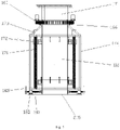
- the stand column rotating mechanism 160 includes an inner rotating ring 161 and an outer rotating ring 162 which are coaxially arranged with the stand column 110 (i.e., the upper stand column unit 111 and the lower stand column unit 112), the outer rotating ring 162 being sleeved outside the inner rotating ring 161.
- the stand column 110 i.e., the upper stand column unit 111 and the lower stand column unit 112
- a movable auxiliary part 167 is arranged between the inner rotating ring 161 and the outer rotating ring 162 to ensure that the inner rotating ring 161 and the outer rotating ring 162 can rotate smoothly with respect to each other.
- the movable auxiliary part 167 may be a rolling body or a lubricant, etc., for example.
- the inner rotating ring 161 is fixed with the upper stand column unit 111 in the circumferential direction
- the outer rotating ring 162 is fixed with the lower stand column unit 112 in the circumferential direction.
- the stand column rotating mechanism 160 further includes a rotating motor.
- the rotating motor includes a rotating motor body 163 fixed with the inner rotating ring, and a rotating driving gear 164 extending out of the rotating motor body 163 and capable of being driven to rotate by the rotating motor body 163.
- the outer rotating ring 162 is constructed with teeth matched and meshed with the rotating driving gear 164.
- the rotating driving gear 164 will actually rotationally move around the outer rotating ring 162, thereby driving the rotating motor body 163 to rotationally move around the central axis of the outer rotating ring 162, and further driving the inner rotating ring 161 fixed thereto to rotate relative to the outer rotating ring 162.
- the upper stand column unit 111 can be effectively caused to rotate relative to the lower stand column unit 112.
- a plurality of rotating motors can be arranged to facilitate driving of the inner rotating ring 161 to rotate.
- an upper support plate 165 extending in the transverse direction is fixedly provided above the inner rotating ring 161, and both the rotating motor body 163 and the upper stand column unit 111 are indirectly and fixedly connected with the inner rotating ring 161 by being fixedly connected with the upper support plate 165.
- a lower support plate 166 extending in the transverse direction is fixedly provided below the outer rotating ring 162, and the lower stand column unit 112 is indirectly and fixedly connected to the outer rotating ring 162 by being fixedly connected to the lower support plate 166.
- the upper support plate 165 includes both a central portion covering the inner rotating ring 161 and an edge portion covering the outer rotating ring 162.
- the central portion is fixedly connected with the inner rotating ring 161 through a screw or bolt.
- the edge portion is spaced from the outer rotating ring 162 to ensure that the upper support plate 165 can rotate relative to the outer rotating ring 162 without relative wear.
- the edge portion of the upper support plate 165 can be made thinner than the central portion.
- the lower support plate 166 may also include a central portion covering the inner rotating ring 161 and an edge portion covering the outer rotating ring.
- the edge portion of the lower support plate 166 is fixedly connected with the outer rotating ring 162 by a screw or bolt.
- the central portion of the lower support plate 166 is spaced from the inner rotating ring 161 to ensure that the inner rotating ring 161 can rotate relative to the lower support plate 166 without relative wear.
- the central portion of the lower support plate 166 can be made thinner than the edge portion.
- the lower support plate 166 may also include only the edge portion and not the central portion.
- the building device 100 further comprises a lifting mechanism 170 for changing a height at which the crossbeam 120 is located.
- Figs. 5 to 8 show a preferred embodiment of the lifting mechanism 170.
- the lifting mechanism 170 includes a lifting lever 171 fixed with the upper stand column unit 111 in the longitudinal direction, and a guide 172 fixed with the lower stand column unit 112.
- the guide 172 is constructed with a guide hole extending along the longitudinal direction, and the lifting lever 171 passes through the guide hole and can be selectively fixed relative to the guide hole.
- the fixing of the upper stand column unit 111 and the lifting lever 171 in the longitudinal direction may be achieved by direct fixing between the upper stand column unit 111 and the lifting lever 171, and may also be achieved by other intermediate structures.
- the lifting mechanism 170 further includes a support frame 174 surrounding the stand column 110.
- the support frame 174 can be fixedly connected to the upper stand column unit 111, and can also be fixedly connected to the lifting lever 171.
- the inner rotating ring 161 of the stand column rotating mechanism 160 may be directly sleeved outside the upper stand column unit 111 and fixed thereto.
- the upper stand column unit 111 includes a portion located above the stand column rotating mechanism 160 and fixed to the inner rotating ring 161, and a portion located below the stand column rotating mechanism 160 and fixed to the outer rotating ring 162.
- the outer rotating ring 162 and the lower support plate 166 are also fixed to the upper stand column unit 111 (or a portion of the upper stand column unit 111 above the stand column rotating mechanism 160) in the longitudinal direction, but can rotate relative to it.
- the support frame 174 can be fixed in the longitudinal direction with the upper stand column unit 111 by being fixed to the outer rotating ring 162 or the lower support plate 166.
- external threads are constructed on an outer surface of the lifting lever 171, while matching internal threads are constructed on an inner wall of the guide hole on the guide 172.
- the lifting mechanism 170 may include a lifting motor 173 fixed to the support frame 174, and the lifting motor can drive the lifting lever 171 to rotate relative to the guide hole.
- the support frame 174 has a substantially rectangular section.
- Four lifting levers and corresponding guides are evenly arranged around the stand column 110 (the lower stand column unit 112) in the circumferential direction within the support frame.
- the lifting mechanism further includes an auxiliary guide lever 175 fixed in the longitudinal direction relative to the lifting lever 171 and extending in the longitudinal direction; a corresponding hole is constructed on the guide 172, and the auxiliary guide lever 175 can pass through the hole and move relative to the hole. In this way, when the lifting lever 171 moves in the longitudinal direction relative to the guide 172, the movement can be guided more stably.
- lifting levers 171 are evenly spaced apart in the circumferential direction of the stand column 110, and two auxiliary guide levers 175 are provided around each of the lifting levers 171.
- Fig. 5 shows the upper stand column unit 111 and the lower stand column unit 112 in contact with each other.
- Driving the lifting rod 171 to rotate by the lifting motor 173 can cause the upper stand column unit 111 to move along the longitudinal direction away from the lower stand column unit 112, so that a gap is formed between the upper stand column unit 111 and the lower stand column unit 112, as shown in Fig. 6 .
- a middle stand column unit 113 may be provided in the gap to support between the upper stand column unit 111 and the lower stand column unit 112.
- the middle stand column unit 113 can be fixedly connected to the lower stand column unit through pins, piercing nails or rivets and other tools.
- the middle stand column unit 113 and the upper stand column unit 111 are not fixedly connected for the time being.
- the upper stand column unit 111, the lower stand column unit 112, and the middle stand column unit 113 herein are all defined for a single lifting for convenience of explanation.
- the middle stand column unit 113 can be used as the lower stand column unit for the next lifting, and a guide is fixed thereon for the next lifting work.
- the upper stand column unit 111 moves upward by a unit distance.
- the unit distance is, for example, 10 cm.
- the middle stand column unit 113 is provided between the upper stand column unit 111 and the lower stand column unit 112.
- the discharging mechanism 130 can move along the crossbeam by the following structures and means.
- the building device 100 comprises a rack 121B arranged along the crossbeam 120, and a transverse moving motor.
- the transverse moving motor includes a transverse moving motor body 123B fixedly connected to the discharging mechanism 130, and a transverse moving gear 122B driven to rotate by the transverse moving motor body 123B, the transverse moving gear 122B meshing with the rack 121B.
- the transverse moving motor body 123B drives the transverse moving gear 122B to rotate
- the transverse moving gear 122B can be rotated to move along the rack 121B, thereby driving the discharging mechanism 130 to move along the rack 121B.
- the crossbeam 120 includes an upper crossbeam and a lower crossbeam; at least a portion of the discharging mechanism 130 (e.g., a feed hopper 131) is positioned between the upper crossbeam and the lower crossbeam; and the rack 121B is fixedly provided along the lower crossbeam. In this way, during the movement of the discharging mechanism 130, the rack 121B can play a certain supporting role, and can closely cooperate with the transverse moving gear 122B.
- the discharging mechanism 130 e.g., a feed hopper 131
- another rack 121A may be fixedly provided on the upper crossbeam 121.
- a transverse moving motor body 123A and a transverse moving gear 122A driven to rotate by the transverse moving motor body 123A are fixedly provided with the feeding mechanism 130.
- the transverse moving gear 122A meshes with the rack 121A and can move along the rack 121A.
- guide rails 124A and 124B are arranged along the upper crossbeam and lower crossbeam respectively, and corresponding sliders 125A and 125B are fixedly provided with the feeding mechanism 130.
- its stability is higher.
- two guide rails 124A spaced apart from each other may be provided on the upper crossbeam, and two sliders 125A are provided in cooperation with each guide rail 124A;
- two guide rails 124B spaced apart from each other may be provided on the lower crossbeam, and two sliders 125B are provided in cooperation with each guide rail 124B.
- the feeding mechanism 130 can be guided very stably.
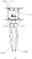
- the feeding mechanism includes a feed hopper 131 arranged between the upper crossbeam and the lower crossbeam, and at least two discharging ports are rotatably connected and communicated with the feed hopper. At least two discharging ports 132A and 132B are provided, and the two discharging ports 132A and 132B are spaced apart from each other and deviate from the longitudinal axis of the discharging mechanism 130. In order to ensure that the discharging mechanism 130 can flexibly convey building materials, the discharging ports 132A and 132B can rotate around the longitudinal axis of the discharging mechanism 130, especially relative to the feed hopper 131.
- the discharging ports 132A and 132B can be driven to rotate by a rotary drive motor 133 arranged between the discharging ports and the feed hopper 131.
- the discharging ports 132A and 132B can be symmetrically arranged relative to a central line of a building wall to be built in a building area.
- the building device 100 is a 3D printing building device, i.e., a 3D printer Through this kind of 3D building printing device, it is possible to promote the mechanization and automation of construction work, and thereby improve the efficiency of the construction field and make up for the shortage of labor force.
- the building device 100 further comprises a storage container 151 for storing building materials or preparatory materials that can be converted into building materials.
- the storage container 151 can be used to store materials as solid particles or powder.
- the storage container 151 can also be provided with wheels to facilitate the movement of the container.
- the storage container 151 may be a pump truck with a drive pump.
- the building device 100 further comprises a conveying pipeline 152 that is in communication with the storage container 151 and extends to the crossbeam 120 for conveying corresponding materials.
- the conveying pipeline 152 can be made to pass through a hollow space inside the stand column 110 and be fixed at least in part with the stand column 110.
- a shock absorber is provided at a fixed position.
- the building device 100 further comprises a conveyor belt 153 arranged along the crossbeam 120.
- An upstream end of the conveyor belt 153 is close to the stand column 110 to receive a material from the conveying pipeline 152.
- a downstream end of the conveyor belt 153 is close to the feed hopper 131 of the discharging mechanism 130 to convey the material into the feed hopper 131.
- the downstream end of the conveyor belt 153 moves synchronously with the discharging mechanism 130 to ensure that the material is effectively conveyed to the discharging mechanism 130.
- an additional drive motor may be provided at the downstream end of the conveyor belt 153, and drive motor works synchronously with the transverse moving motor.
- the crossbeam 120 can extend in two opposite extension directions, and in one of the extension directions, the discharging mechanism 130 is connected with the crossbeam 120.
- a balance mechanism 140 connected with the crossbeam 120 can be provided in another opposite extension direction, and the balance mechanism 140 can move along the crossbeam 120.
- the building device 100 can also comprise a controller that can be used to control the working processes of the various structures described above.
- the drawing data of the building structure to be built can be input into the controller.
- a control system identifies and reads the drawing data, and instructs a corresponding structure to complete the 3D printing process, i.e., the construction process.
- a remote design can also be carried out through the Internet and the internet can be connected with the 3D printer.
- the data of architectural drawings are transmitted to a 3D printer through a computer for architectural printing.
- a monitoring device especially a network monitoring device, connected with the controller, can also be provided so that operators can control the working process of the building device 100 in real time.
- the monitoring device can transmit and record the working process of the building device 100.
- the network can also be used to manage and track the building device 100 using the principle of thermal sensing, so as to maintain and repair the building device 100 in time.
- All of the motors herein are preferably servo motors.
- the servo motor has the advantages of fast response, accurate positioning, large inertia, and excellent operation performance.
Landscapes
- Engineering & Computer Science (AREA)
- Architecture (AREA)
- Mechanical Engineering (AREA)
- Structural Engineering (AREA)
- Chemical & Material Sciences (AREA)
- Manufacturing & Machinery (AREA)
- Materials Engineering (AREA)
- Civil Engineering (AREA)
- Transportation (AREA)
- Conveying And Assembling Of Building Elements In Situ (AREA)
- Tents Or Canopies (AREA)
Claims (8)
- Dispositif de construction (100), qui est un dispositif de construction à impression 3D, comprenant :- une colonne de support (110) s'étendant dans un sens longitudinal,- une traverse (120) s'étendant dans un sens transversal, la traverse (120) étant reliée à la colonne de support (110) et pouvant tourner autour d'un axe central de la colonne de support (110), la traverse (120) comprenant une traverse supérieure (121) et une traverse inférieure, et- un mécanisme de décharge (130) relié à la traverse (120) et pouvant se déplacer le long de la traverse (120), un orifice de décharge (132A, 132B) du mécanisme de décharge (130) faisant face à une zone de construction,caractérisé en ce que- le mécanisme de décharge (130) est réalisé avec au moins deux orifices de décharge (132A, 132B) espacés l'un de l'autre et déviés d'un axe central du mécanisme de décharge (130),- au moins une trémie d'entrée (131) du mécanisme de décharge (130) est positionnée entre la traverse supérieure (121) et la traverse inférieure,- les orifices de décharge (132A, 132B) sont reliés de manière rotative et communiquent avec la trémie d'entrée (131),- les orifices de décharge (132A, 132B) pouvant tourner autour de l'axe central du mécanisme de décharge (130), et par rapport à la trémie d'entrée (131), et en ce que- les orifices de décharge (132A, 132B) peuvent être disposés symétriquement par rapport à une ligne centrale d'un mur de bâtiment à construire dans une zone de construction.
- Dispositif de construction selon la revendication 1, caractérisé en ce que la colonne de support (110) comporte une unité de colonne de support inférieure (112) et une unité de colonne de support supérieure (111) située au-dessus de l'unité de colonne de support inférieure (112) ; la traverse (120) est reliée à demeure à l'unité de colonne de support supérieure (111) ; et l'unité de colonne de support supérieure (111) peut tourner autour de l'axe central de la colonne de support (110) par rapport à l'unité de colonne de support inférieure (112).
- Dispositif de construction selon la revendication 2, caractérisé en ce que le dispositif de construction comprend un mécanisme de rotation de colonne de support (160) qui comporte :une bague rotative intérieure (161) gainée à l'extérieur de la colonne de support (110), la bague rotative intérieure (161) étant fixée à l'unité de colonne de support supérieure (111) dans un sens circonférentiel ;une bague rotative extérieure (162) gainée à l'extérieur de la bague rotative intérieure (161), la bague rotative extérieure (162) étant fixée à l'unité de colonne de support inférieure (112) dans un sens circonférentiel, la bague rotative intérieure (161) pouvant tourner par rapport à la bague rotative extérieure (162), et une surface extérieure de la bague rotative extérieure (162) étant réalisée avec des dents ; etun moteur rotatif comportant un corps de moteur rotatif (163) fixé à la bague rotative intérieure (161), et un engrenage d'entraînement rotatif (164) relié de manière rotative au corps de moteur rotatif (163), l'engrenage d'entraînement rotatif (164) s'engrenant avec les dents sur la surface extérieure de la bague rotative extérieure (162).
- Dispositif de construction selon la revendication 1 ou 2, caractérisé en ce que la colonne de support (110) comporte une unité de colonne de support inférieure (112) et une unité de colonne de support supérieure (111) située au-dessus de l'unité de colonne de support inférieure (112), la traverse (120) étant reliée à demeure à l'unité de colonne de support supérieure (111) ;le dispositif de construction comprend en outre un mécanisme de levage (170) qui comporte :un levier de levage (171) fixé à l'unité de colonne de support supérieure (111) dans le sens longitudinal ; etun guide (172) fixé sur l'unité de colonne de support inférieure (112) et réalisé avec un trou de guidage s'étendant le long du sens longitudinal,en ce que le levier de levage (171) peut se déplacer dans le sens longitudinal par rapport au trou de guidage pour entraîner l'unité de colonne de support supérieure (111) à se déplacer dans le sens longitudinal par rapport à l'unité de colonne de support inférieure (112).
- Dispositif de construction selon la revendication 4, caractérisé en ce que des filetages externes sont réalisés sur une surface extérieure du levier de levage (171), et des filetages internes sont réalisés sur une surface intérieure du trou de guidage, les filetages externes sur le levier de levage (171) s'engrenant avec les filetages internes sur le trou de guidage ;
le mécanisme de levage (170) comprend en outre :un cadre de support (174) gainé à l'extérieur de la colonne de support (110) et fixé à l'unité de colonne de support supérieure (111) et le levier de levage (171) dans le sens longitudinal, etun moteur de levage (173) fixé au cadre de support (174) et réalisé pour entraîner le levier de levage (171) à tourner par rapport au trou de guidage. - Dispositif de construction selon la revendication 4 ou 5, caractérisé en ce que la colonne de support (110) comporte en outre une unité de colonne de support centrale (113) qui est ménagée dans un espace destiné au support entre l'unité de colonne de support supérieure (111) et l'unité de colonne de support inférieure (112) lorsque l'unité de colonne de support supérieure (111) s'éloigne de l'unité de colonne de support inférieure (112) dans le sens longitudinal pour former l'espace entre l'unité de colonne de support supérieure (111) et l'unité de colonne de support inférieure (112),
en ce que l'unité de colonne de support supérieure (111) s'éloigne de l'unité de colonne de support inférieure (112) d'une distance unitaire dans le sens longitudinal une fois la réalisation de chaque couche de corps de construction en utilisant le dispositif de construction (100), et l'unité de colonne de support centrale (113) est ménagée dans l'espace après que l'unité de colonne de support supérieure (111) s'éloigne de l'unité de colonne de support inférieure (112) d'une pluralité de distances unitaires. - Dispositif de construction selon l'une des revendications 1 à 6, caractérisé en ce que le dispositif de construction (100) comprend en outre un mécanisme de calibrage vertical qui comporte :un composant de mesure pour mesurer si l'axe central de la colonne de support (110) est exactement perpendiculaire à une surface de base, etun composant d'ajustage comprenant :une partie fixe (182) fixée à la surface de base (205) et réalisée avec un trou de réception dont l'axe est parallèle à la surface de base (205), une paroi intérieure du trou de réception étant réalisée avec des filetages internes ; etun levier d'ajustage de correction (181) passant par le trou de réception, une surface extérieure du levier d'ajustage de correction (181) étant réalisée avec des filetages externes correspondant aux filetages internes du trou de réception, et une extrémité du levier d'ajustage de correction (181) étant articulée avec la colonne de support (110).
- Dispositif de construction selon l'une des revendications 1 à 7, caractérisé en ce que le dispositif de construction (100) comprend en outre :une crémaillère (121B) disposée le long de la traverse (120), etun moteur de déplacement transversal comportant un corps de moteur de déplacement transversal (123B) fixé au mécanisme de décharge (130), et un engrenage de déplacement transversal (122B) entraîné par le corps de moteur de déplacement transversal (123B), l'engrenage de déplacement transversal (122B) s'engrenant avec la crémaillère (121B).
Applications Claiming Priority (2)
| Application Number | Priority Date | Filing Date | Title |
|---|---|---|---|
| CN201710660901.7A CN107447985A (zh) | 2017-08-04 | 2017-08-04 | 建筑装置及房屋 |
| PCT/CN2018/097544 WO2019024807A1 (fr) | 2017-08-04 | 2018-07-27 | Dispositif de construction et maison |
Publications (3)
| Publication Number | Publication Date |
|---|---|
| EP3663485A1 EP3663485A1 (fr) | 2020-06-10 |
| EP3663485A4 EP3663485A4 (fr) | 2021-07-21 |
| EP3663485B1 true EP3663485B1 (fr) | 2022-12-21 |
Family
ID=60490514
Family Applications (1)
| Application Number | Title | Priority Date | Filing Date |
|---|---|---|---|
| EP18840824.9A Active EP3663485B1 (fr) | 2017-08-04 | 2018-07-27 | Dispositif de construction et maison |
Country Status (4)
| Country | Link |
|---|---|
| EP (1) | EP3663485B1 (fr) |
| CN (2) | CN107447985A (fr) |
| ES (1) | ES2940640T3 (fr) |
| WO (1) | WO2019024807A1 (fr) |
Families Citing this family (23)
| Publication number | Priority date | Publication date | Assignee | Title |
|---|---|---|---|---|
| CN107447985A (zh) * | 2017-08-04 | 2017-12-08 | 北京华商陆海科技有限公司 | 建筑装置及房屋 |
| CN108437156A (zh) * | 2018-05-18 | 2018-08-24 | 天津依蓝时代电气设备有限公司 | 监测调整系统及3d房屋打印机 |
| CN108908928B (zh) * | 2018-07-10 | 2021-02-19 | 深圳市三帝梦工场科技开发有限公司 | 采用热熔水泥的大型3d打印机 |
| IT201800008060A1 (it) * | 2018-08-10 | 2020-02-10 | Csp Srl | Apparato per la stampa 3d di edifici |
| WO2020065375A1 (fr) * | 2018-09-26 | 2020-04-02 | Trawi 3D Constructions S.A.R.L. | Appareil d'impression en trois dimensions |
| WO2021108935A1 (fr) * | 2019-12-05 | 2021-06-10 | Universidad Técnica Federico Santa María | Cellule robotisée mobile pour la fabrication de pièces avec armature ou conduits verticaux pré-installés dans sa partie interne et enceintes imprimées sur site au moyen d'un système multi-axes d'impression 3d ; et procédé de fonctionnement |
| WO2021108933A1 (fr) * | 2019-12-05 | 2021-06-10 | Universidad Técnica Federico Santa María | Cellule robotisée mobile pour la fabrication de pièces et enceintes imprimées lors de travaux au moyen d'un système à axes multiples d'impression 3d, et procédé de fonctionnement associé |
| WO2021136956A1 (fr) * | 2019-12-30 | 2021-07-08 | Medcom France S.R.O | Système de construction automatisé |
| CN112096079B (zh) * | 2020-08-11 | 2025-06-27 | 北京华商陆海科技有限公司 | 3d打印机的打印材料输送装置 |
| CN112096081A (zh) * | 2020-09-15 | 2020-12-18 | 栾勇 | 一种多角度自动水泥浇灌系统 |
| CN112523510B (zh) * | 2020-10-28 | 2024-09-20 | 北京华商陆海科技有限公司 | 用于3d打印机的打印头装置及3d打印机 |
| CN112661534A (zh) * | 2020-12-21 | 2021-04-16 | 成都锐龙机械制造有限公司 | 一种隧道二衬混凝土喷淋养护台车 |
| CN112796530B (zh) * | 2021-01-27 | 2024-11-01 | 广西浩通建筑机械制造有限公司 | 一种建筑用液压内循环平衡撑杆式伸缩平台 |
| CN113682938A (zh) * | 2021-07-21 | 2021-11-23 | 青岛博海建设集团有限公司 | 一种可实现横向调节的建筑水泥砌块装卸装置 |
| CN113445742A (zh) * | 2021-08-02 | 2021-09-28 | 吴慧珍 | 一种全装修的装配式房屋施工装置 |
| CN113734953B (zh) * | 2021-09-28 | 2023-07-18 | 济南一建集团绿色建筑产业有限公司 | 一种装配式建筑用墙板吊装坐定可视化设备 |
| CN114321587B (zh) * | 2021-12-15 | 2024-07-09 | 北京华商陆海科技有限公司 | 塔式设备的稳定装置及稳定方法 |
| CN114485428B (zh) * | 2021-12-22 | 2024-12-27 | 青岛金沙滩建设集团有限公司 | 一种可减少复位时间的建筑预制构件外形尺寸测量装置 |
| CN114367161B (zh) * | 2022-01-19 | 2023-06-09 | 周冯兰 | 一种建筑工程用的扬尘治理环保装置 |
| CN114908973B (zh) * | 2022-04-07 | 2025-07-08 | 江苏泰高建设有限公司 | 一种用于房屋建设的混凝土无气泡灌装填充设备 |
| CN114908975A (zh) * | 2022-05-31 | 2022-08-16 | 湖州众驰建材有限公司 | 一种混凝土浇灌用安全输送装置 |
| CN116969350B (zh) * | 2023-07-28 | 2024-11-15 | 中国长江三峡集团有限公司 | 塔吊设备及其安装方法、控制方法 |
| CN118187456B (zh) * | 2024-05-15 | 2024-08-20 | 山西八建集团有限公司 | 一种高空狭小空间内混凝土浇筑输送装置 |
Family Cites Families (17)
| Publication number | Priority date | Publication date | Assignee | Title |
|---|---|---|---|---|
| CN2224273Y (zh) * | 1995-06-16 | 1996-04-10 | 曾绍强 | 标准转盘上回转附着式提升井架塔吊 |
| DE29521389U1 (de) * | 1995-12-28 | 1997-02-13 | Dyckerhoff & Widmann AG, 81902 München | Turmkran mit Betonverteilereinrichtung |
| KR20060037570A (ko) * | 2004-10-28 | 2006-05-03 | 유광철 | 콘크리트 분배기용 회전장치 |
| ITPR20060033A1 (it) * | 2006-04-05 | 2007-10-06 | Tgm Srl | Gru e suo metodo di assemblaggio. |
| CN201730340U (zh) * | 2010-06-11 | 2011-02-02 | 中国一冶集团有限公司 | 双出口混凝土下料料斗 |
| CN102409865A (zh) * | 2011-08-17 | 2012-04-11 | 安徽富煌钢构股份有限公司 | 一种多高层钢结构柱安装测量校正结构 |
| CN202449178U (zh) * | 2012-01-19 | 2012-09-26 | 张伟鑫 | 浮体及建在浮体上的水上建筑 |
| US20150361681A1 (en) * | 2013-01-31 | 2015-12-17 | Huan DAO | Combination of concrete spreader and crane tower |
| CN103786235B (zh) * | 2014-01-09 | 2016-01-27 | 中建钢构有限公司 | 一种塔式3d打印机及其打印方法 |
| CN105668425A (zh) * | 2014-12-07 | 2016-06-15 | 苏州汇诚智造工业设计有限公司 | 一种建筑施工用多功能塔吊的施工方法 |
| CN204507204U (zh) * | 2014-12-29 | 2015-07-29 | 浙江海洋学院 | 一种半潜式水上漂浮屋 |
| CN204526175U (zh) * | 2015-03-09 | 2015-08-05 | 广东工业大学 | 一种多喷嘴3d打印机喷头 |
| WO2016166116A1 (fr) * | 2015-04-12 | 2016-10-20 | Imprimere Ag | Imprimante à béton et procédé servant à ériger des bâtiments au moyen d'une imprimante à béton |
| CN105604336A (zh) * | 2016-01-25 | 2016-05-25 | 中国十九冶集团有限公司 | 钢柱安装定位装置及安装定位方法 |
| CN205439277U (zh) * | 2016-03-09 | 2016-08-10 | 四川大学 | 一种悬臂式机械手3d打印装置 |
| CN106760574A (zh) * | 2017-01-17 | 2017-05-31 | 上海建工建集团有限公司 | 逆作法一柱一桩中矩形钢管柱施工调垂装置及调垂方法 |
| CN107447985A (zh) * | 2017-08-04 | 2017-12-08 | 北京华商陆海科技有限公司 | 建筑装置及房屋 |
-
2017
- 2017-08-04 CN CN201710660901.7A patent/CN107447985A/zh active Pending
-
2018
- 2018-07-27 CN CN201810841600.9A patent/CN109386135B/zh active Active
- 2018-07-27 EP EP18840824.9A patent/EP3663485B1/fr active Active
- 2018-07-27 ES ES18840824T patent/ES2940640T3/es active Active
- 2018-07-27 WO PCT/CN2018/097544 patent/WO2019024807A1/fr not_active Ceased
Also Published As
| Publication number | Publication date |
|---|---|
| CN109386135A (zh) | 2019-02-26 |
| EP3663485A1 (fr) | 2020-06-10 |
| WO2019024807A1 (fr) | 2019-02-07 |
| ES2940640T3 (es) | 2023-05-10 |
| EP3663485A4 (fr) | 2021-07-21 |
| CN109386135B (zh) | 2019-11-08 |
| CN107447985A (zh) | 2017-12-08 |
Similar Documents
| Publication | Publication Date | Title |
|---|---|---|
| EP3663485B1 (fr) | Dispositif de construction et maison | |
| KR101178422B1 (ko) | 프레스 소재 이송장치 | |
| CN101890711B (zh) | 机器人系统 | |
| CN102020113A (zh) | 装校搬运机械手 | |
| CN207866550U (zh) | 一种自动定位钻孔的岩芯取样机 | |
| CN105562763A (zh) | 一种led灯灯盖钻孔加工控制系统 | |
| CN113816118A (zh) | 一种ic芯片检测上料工装 | |
| CN202527882U (zh) | 截齿定位工装 | |
| CN112405890A (zh) | 一种建筑桥梁施工现场用打孔装置 | |
| CN104316152A (zh) | 辅料称重装置 | |
| CN108032055A (zh) | 用于智能装配平台的瓷柱送料设备 | |
| CN215665954U (zh) | 一种机器人码垛装置 | |
| US20230166449A1 (en) | 3d printer | |
| CN224161674U (zh) | 桥梁修建施工装置 | |
| CN208458739U (zh) | 一种用于固定光学仪器的工作台及激光投线仪 | |
| CN116729914A (zh) | 一种工业自动化设备减震转运装置 | |
| CN210918878U (zh) | 一种建筑设计用地质勘察钻探装置 | |
| JP2003246599A (ja) | レベラー | |
| CN207858176U (zh) | 用于传送瓷柱的智能送料设备 | |
| CN109315305B (zh) | 宠物饲料自动均分装置 | |
| CN111014751A (zh) | 一种摇臂钻床加工用精度调节装置 | |
| CN204228247U (zh) | 辅料称重装置 | |
| CN209477733U (zh) | 可转动角度机械手及加工系统 | |
| CN214720777U (zh) | 一种建筑用精度钻孔装置 | |
| CN220295880U (zh) | 一种定位精确的钻床 |
Legal Events
| Date | Code | Title | Description |
|---|---|---|---|
| STAA | Information on the status of an ep patent application or granted ep patent |
Free format text: STATUS: THE INTERNATIONAL PUBLICATION HAS BEEN MADE |
|
| PUAI | Public reference made under article 153(3) epc to a published international application that has entered the european phase |
Free format text: ORIGINAL CODE: 0009012 |
|
| STAA | Information on the status of an ep patent application or granted ep patent |
Free format text: STATUS: REQUEST FOR EXAMINATION WAS MADE |
|
| 17P | Request for examination filed |
Effective date: 20190717 |
|
| AK | Designated contracting states |
Kind code of ref document: A1 Designated state(s): AL AT BE BG CH CY CZ DE DK EE ES FI FR GB GR HR HU IE IS IT LI LT LU LV MC MK MT NL NO PL PT RO RS SE SI SK SM TR |
|
| RIC1 | Information provided on ipc code assigned before grant |
Ipc: E04G 21/02 20060101AFI20210312BHEP Ipc: B63B 35/44 20060101ALI20210312BHEP Ipc: E04G 21/04 20060101ALI20210312BHEP Ipc: B66C 23/34 20060101ALI20210312BHEP Ipc: B66C 23/84 20060101ALI20210312BHEP Ipc: B66C 23/32 20060101ALI20210312BHEP Ipc: B66C 23/28 20060101ALI20210312BHEP Ipc: B33Y 80/00 20150101ALI20210312BHEP Ipc: B33Y 10/00 20150101ALI20210312BHEP Ipc: B33Y 30/00 20150101ALI20210312BHEP |
|
| RIN1 | Information on inventor provided before grant (corrected) |
Inventor name: WU, JIANPING |
|
| A4 | Supplementary search report drawn up and despatched |
Effective date: 20210621 |
|
| RIC1 | Information provided on ipc code assigned before grant |
Ipc: E04G 21/02 20060101AFI20210615BHEP Ipc: B63B 35/44 20060101ALI20210615BHEP Ipc: E04G 21/04 20060101ALI20210615BHEP Ipc: B66C 23/34 20060101ALI20210615BHEP Ipc: B66C 23/84 20060101ALI20210615BHEP Ipc: B66C 23/32 20060101ALI20210615BHEP Ipc: B66C 23/28 20060101ALI20210615BHEP Ipc: B33Y 80/00 20150101ALI20210615BHEP Ipc: B33Y 10/00 20150101ALI20210615BHEP Ipc: B33Y 30/00 20150101ALI20210615BHEP |
|
| STAA | Information on the status of an ep patent application or granted ep patent |
Free format text: STATUS: EXAMINATION IS IN PROGRESS |
|
| 17Q | First examination report despatched |
Effective date: 20220218 |
|
| GRAP | Despatch of communication of intention to grant a patent |
Free format text: ORIGINAL CODE: EPIDOSNIGR1 |
|
| STAA | Information on the status of an ep patent application or granted ep patent |
Free format text: STATUS: GRANT OF PATENT IS INTENDED |
|
| INTG | Intention to grant announced |
Effective date: 20220902 |
|
| GRAS | Grant fee paid |
Free format text: ORIGINAL CODE: EPIDOSNIGR3 |
|
| GRAA | (expected) grant |
Free format text: ORIGINAL CODE: 0009210 |
|
| STAA | Information on the status of an ep patent application or granted ep patent |
Free format text: STATUS: THE PATENT HAS BEEN GRANTED |
|
| AK | Designated contracting states |
Kind code of ref document: B1 Designated state(s): AL AT BE BG CH CY CZ DE DK EE ES FI FR GB GR HR HU IE IS IT LI LT LU LV MC MK MT NL NO PL PT RO RS SE SI SK SM TR |
|
| REG | Reference to a national code |
Ref country code: GB Ref legal event code: FG4D |
|
| REG | Reference to a national code |
Ref country code: CH Ref legal event code: EP |
|
| REG | Reference to a national code |
Ref country code: DE Ref legal event code: R096 Ref document number: 602018044576 Country of ref document: DE |
|
| REG | Reference to a national code |
Ref country code: AT Ref legal event code: REF Ref document number: 1539140 Country of ref document: AT Kind code of ref document: T Effective date: 20230115 |
|
| REG | Reference to a national code |
Ref country code: IE Ref legal event code: FG4D |
|
| REG | Reference to a national code |
Ref country code: NL Ref legal event code: FP |
|
| REG | Reference to a national code |
Ref country code: LT Ref legal event code: MG9D |
|
| PG25 | Lapsed in a contracting state [announced via postgrant information from national office to epo] |
Ref country code: SE Free format text: LAPSE BECAUSE OF FAILURE TO SUBMIT A TRANSLATION OF THE DESCRIPTION OR TO PAY THE FEE WITHIN THE PRESCRIBED TIME-LIMIT Effective date: 20221221 Ref country code: NO Free format text: LAPSE BECAUSE OF FAILURE TO SUBMIT A TRANSLATION OF THE DESCRIPTION OR TO PAY THE FEE WITHIN THE PRESCRIBED TIME-LIMIT Effective date: 20230321 Ref country code: LT Free format text: LAPSE BECAUSE OF FAILURE TO SUBMIT A TRANSLATION OF THE DESCRIPTION OR TO PAY THE FEE WITHIN THE PRESCRIBED TIME-LIMIT Effective date: 20221221 Ref country code: FI Free format text: LAPSE BECAUSE OF FAILURE TO SUBMIT A TRANSLATION OF THE DESCRIPTION OR TO PAY THE FEE WITHIN THE PRESCRIBED TIME-LIMIT Effective date: 20221221 |
|
| REG | Reference to a national code |
Ref country code: ES Ref legal event code: FG2A Ref document number: 2940640 Country of ref document: ES Kind code of ref document: T3 Effective date: 20230510 |
|
| REG | Reference to a national code |
Ref country code: AT Ref legal event code: MK05 Ref document number: 1539140 Country of ref document: AT Kind code of ref document: T Effective date: 20221221 |
|
| PG25 | Lapsed in a contracting state [announced via postgrant information from national office to epo] |
Ref country code: RS Free format text: LAPSE BECAUSE OF FAILURE TO SUBMIT A TRANSLATION OF THE DESCRIPTION OR TO PAY THE FEE WITHIN THE PRESCRIBED TIME-LIMIT Effective date: 20221221 Ref country code: LV Free format text: LAPSE BECAUSE OF FAILURE TO SUBMIT A TRANSLATION OF THE DESCRIPTION OR TO PAY THE FEE WITHIN THE PRESCRIBED TIME-LIMIT Effective date: 20221221 Ref country code: HR Free format text: LAPSE BECAUSE OF FAILURE TO SUBMIT A TRANSLATION OF THE DESCRIPTION OR TO PAY THE FEE WITHIN THE PRESCRIBED TIME-LIMIT Effective date: 20221221 Ref country code: GR Free format text: LAPSE BECAUSE OF FAILURE TO SUBMIT A TRANSLATION OF THE DESCRIPTION OR TO PAY THE FEE WITHIN THE PRESCRIBED TIME-LIMIT Effective date: 20230322 |
|
| P01 | Opt-out of the competence of the unified patent court (upc) registered |
Effective date: 20230414 |
|
| PG25 | Lapsed in a contracting state [announced via postgrant information from national office to epo] |
Ref country code: SM Free format text: LAPSE BECAUSE OF FAILURE TO SUBMIT A TRANSLATION OF THE DESCRIPTION OR TO PAY THE FEE WITHIN THE PRESCRIBED TIME-LIMIT Effective date: 20221221 Ref country code: RO Free format text: LAPSE BECAUSE OF FAILURE TO SUBMIT A TRANSLATION OF THE DESCRIPTION OR TO PAY THE FEE WITHIN THE PRESCRIBED TIME-LIMIT Effective date: 20221221 Ref country code: PT Free format text: LAPSE BECAUSE OF FAILURE TO SUBMIT A TRANSLATION OF THE DESCRIPTION OR TO PAY THE FEE WITHIN THE PRESCRIBED TIME-LIMIT Effective date: 20230421 Ref country code: EE Free format text: LAPSE BECAUSE OF FAILURE TO SUBMIT A TRANSLATION OF THE DESCRIPTION OR TO PAY THE FEE WITHIN THE PRESCRIBED TIME-LIMIT Effective date: 20221221 Ref country code: CZ Free format text: LAPSE BECAUSE OF FAILURE TO SUBMIT A TRANSLATION OF THE DESCRIPTION OR TO PAY THE FEE WITHIN THE PRESCRIBED TIME-LIMIT Effective date: 20221221 Ref country code: AT Free format text: LAPSE BECAUSE OF FAILURE TO SUBMIT A TRANSLATION OF THE DESCRIPTION OR TO PAY THE FEE WITHIN THE PRESCRIBED TIME-LIMIT Effective date: 20221221 |
|
| PG25 | Lapsed in a contracting state [announced via postgrant information from national office to epo] |
Ref country code: SK Free format text: LAPSE BECAUSE OF FAILURE TO SUBMIT A TRANSLATION OF THE DESCRIPTION OR TO PAY THE FEE WITHIN THE PRESCRIBED TIME-LIMIT Effective date: 20221221 Ref country code: PL Free format text: LAPSE BECAUSE OF FAILURE TO SUBMIT A TRANSLATION OF THE DESCRIPTION OR TO PAY THE FEE WITHIN THE PRESCRIBED TIME-LIMIT Effective date: 20221221 Ref country code: IS Free format text: LAPSE BECAUSE OF FAILURE TO SUBMIT A TRANSLATION OF THE DESCRIPTION OR TO PAY THE FEE WITHIN THE PRESCRIBED TIME-LIMIT Effective date: 20230421 Ref country code: AL Free format text: LAPSE BECAUSE OF FAILURE TO SUBMIT A TRANSLATION OF THE DESCRIPTION OR TO PAY THE FEE WITHIN THE PRESCRIBED TIME-LIMIT Effective date: 20221221 |
|
| REG | Reference to a national code |
Ref country code: DE Ref legal event code: R097 Ref document number: 602018044576 Country of ref document: DE |
|
| PLBE | No opposition filed within time limit |
Free format text: ORIGINAL CODE: 0009261 |
|
| STAA | Information on the status of an ep patent application or granted ep patent |
Free format text: STATUS: NO OPPOSITION FILED WITHIN TIME LIMIT |
|
| PG25 | Lapsed in a contracting state [announced via postgrant information from national office to epo] |
Ref country code: DK Free format text: LAPSE BECAUSE OF FAILURE TO SUBMIT A TRANSLATION OF THE DESCRIPTION OR TO PAY THE FEE WITHIN THE PRESCRIBED TIME-LIMIT Effective date: 20221221 |
|
| 26N | No opposition filed |
Effective date: 20230922 |
|
| PG25 | Lapsed in a contracting state [announced via postgrant information from national office to epo] |
Ref country code: SI Free format text: LAPSE BECAUSE OF FAILURE TO SUBMIT A TRANSLATION OF THE DESCRIPTION OR TO PAY THE FEE WITHIN THE PRESCRIBED TIME-LIMIT Effective date: 20221221 |
|
| PG25 | Lapsed in a contracting state [announced via postgrant information from national office to epo] |
Ref country code: MC Free format text: LAPSE BECAUSE OF FAILURE TO SUBMIT A TRANSLATION OF THE DESCRIPTION OR TO PAY THE FEE WITHIN THE PRESCRIBED TIME-LIMIT Effective date: 20221221 |
|
| PG25 | Lapsed in a contracting state [announced via postgrant information from national office to epo] |
Ref country code: MC Free format text: LAPSE BECAUSE OF FAILURE TO SUBMIT A TRANSLATION OF THE DESCRIPTION OR TO PAY THE FEE WITHIN THE PRESCRIBED TIME-LIMIT Effective date: 20221221 |
|
| REG | Reference to a national code |
Ref country code: CH Ref legal event code: PL |
|
| REG | Reference to a national code |
Ref country code: BE Ref legal event code: MM Effective date: 20230731 |
|
| PG25 | Lapsed in a contracting state [announced via postgrant information from national office to epo] |
Ref country code: LU Free format text: LAPSE BECAUSE OF NON-PAYMENT OF DUE FEES Effective date: 20230727 |
|
| PG25 | Lapsed in a contracting state [announced via postgrant information from national office to epo] |
Ref country code: LU Free format text: LAPSE BECAUSE OF NON-PAYMENT OF DUE FEES Effective date: 20230727 |
|
| REG | Reference to a national code |
Ref country code: IE Ref legal event code: MM4A |
|
| PG25 | Lapsed in a contracting state [announced via postgrant information from national office to epo] |
Ref country code: CH Free format text: LAPSE BECAUSE OF NON-PAYMENT OF DUE FEES Effective date: 20230731 |
|
| PG25 | Lapsed in a contracting state [announced via postgrant information from national office to epo] |
Ref country code: BE Free format text: LAPSE BECAUSE OF NON-PAYMENT OF DUE FEES Effective date: 20230731 |
|
| PG25 | Lapsed in a contracting state [announced via postgrant information from national office to epo] |
Ref country code: IE Free format text: LAPSE BECAUSE OF NON-PAYMENT OF DUE FEES Effective date: 20230727 |
|
| PG25 | Lapsed in a contracting state [announced via postgrant information from national office to epo] |
Ref country code: IE Free format text: LAPSE BECAUSE OF NON-PAYMENT OF DUE FEES Effective date: 20230727 |
|
| PGFP | Annual fee paid to national office [announced via postgrant information from national office to epo] |
Ref country code: NL Payment date: 20240722 Year of fee payment: 7 |
|
| PGFP | Annual fee paid to national office [announced via postgrant information from national office to epo] |
Ref country code: DE Payment date: 20240709 Year of fee payment: 7 |
|
| PGFP | Annual fee paid to national office [announced via postgrant information from national office to epo] |
Ref country code: GB Payment date: 20240723 Year of fee payment: 7 |
|
| PGFP | Annual fee paid to national office [announced via postgrant information from national office to epo] |
Ref country code: FR Payment date: 20240724 Year of fee payment: 7 |
|
| PGFP | Annual fee paid to national office [announced via postgrant information from national office to epo] |
Ref country code: ES Payment date: 20240816 Year of fee payment: 7 |
|
| PGFP | Annual fee paid to national office [announced via postgrant information from national office to epo] |
Ref country code: IT Payment date: 20240731 Year of fee payment: 7 |
|
| PG25 | Lapsed in a contracting state [announced via postgrant information from national office to epo] |
Ref country code: BG Free format text: LAPSE BECAUSE OF FAILURE TO SUBMIT A TRANSLATION OF THE DESCRIPTION OR TO PAY THE FEE WITHIN THE PRESCRIBED TIME-LIMIT Effective date: 20221221 |
|
| PG25 | Lapsed in a contracting state [announced via postgrant information from national office to epo] |
Ref country code: BG Free format text: LAPSE BECAUSE OF FAILURE TO SUBMIT A TRANSLATION OF THE DESCRIPTION OR TO PAY THE FEE WITHIN THE PRESCRIBED TIME-LIMIT Effective date: 20221221 |
|
| PG25 | Lapsed in a contracting state [announced via postgrant information from national office to epo] |
Ref country code: CY Free format text: LAPSE BECAUSE OF FAILURE TO SUBMIT A TRANSLATION OF THE DESCRIPTION OR TO PAY THE FEE WITHIN THE PRESCRIBED TIME-LIMIT; INVALID AB INITIO Effective date: 20180727 |
|
| PG25 | Lapsed in a contracting state [announced via postgrant information from national office to epo] |
Ref country code: HU Free format text: LAPSE BECAUSE OF FAILURE TO SUBMIT A TRANSLATION OF THE DESCRIPTION OR TO PAY THE FEE WITHIN THE PRESCRIBED TIME-LIMIT; INVALID AB INITIO Effective date: 20180727 |
|
| PG25 | Lapsed in a contracting state [announced via postgrant information from national office to epo] |
Ref country code: TR Free format text: LAPSE BECAUSE OF FAILURE TO SUBMIT A TRANSLATION OF THE DESCRIPTION OR TO PAY THE FEE WITHIN THE PRESCRIBED TIME-LIMIT Effective date: 20221221 |
|
| REG | Reference to a national code |
Ref country code: DE Ref legal event code: R119 Ref document number: 602018044576 Country of ref document: DE |
|
| REG | Reference to a national code |
Ref country code: NL Ref legal event code: MM Effective date: 20250801 |
|
| GBPC | Gb: european patent ceased through non-payment of renewal fee |
Effective date: 20250727 |
|
| PG25 | Lapsed in a contracting state [announced via postgrant information from national office to epo] |
Ref country code: GB Free format text: LAPSE BECAUSE OF NON-PAYMENT OF DUE FEES Effective date: 20250727 |
|
| PG25 | Lapsed in a contracting state [announced via postgrant information from national office to epo] |
Ref country code: DE Free format text: LAPSE BECAUSE OF NON-PAYMENT OF DUE FEES Effective date: 20260203 |
|
| PG25 | Lapsed in a contracting state [announced via postgrant information from national office to epo] |
Ref country code: NL Free format text: LAPSE BECAUSE OF NON-PAYMENT OF DUE FEES Effective date: 20250801 |
|
| PG25 | Lapsed in a contracting state [announced via postgrant information from national office to epo] |
Ref country code: FR Free format text: LAPSE BECAUSE OF NON-PAYMENT OF DUE FEES Effective date: 20250731 |