EP3663487B1 - Robot de stationnement pour un véhicule automobile ainsi que procédé de fonctionnement d'un tel robot de stationnement - Google Patents
Robot de stationnement pour un véhicule automobile ainsi que procédé de fonctionnement d'un tel robot de stationnement Download PDFInfo
- Publication number
- EP3663487B1 EP3663487B1 EP19204991.4A EP19204991A EP3663487B1 EP 3663487 B1 EP3663487 B1 EP 3663487B1 EP 19204991 A EP19204991 A EP 19204991A EP 3663487 B1 EP3663487 B1 EP 3663487B1
- Authority
- EP
- European Patent Office
- Prior art keywords
- wheel
- parking robot
- motor vehicle
- parking
- rotation
- Prior art date
- Legal status (The legal status is an assumption and is not a legal conclusion. Google has not performed a legal analysis and makes no representation as to the accuracy of the status listed.)
- Active
Links
Images

Classifications
-
- B—PERFORMING OPERATIONS; TRANSPORTING
- B62—LAND VEHICLES FOR TRAVELLING OTHERWISE THAN ON RAILS
- B62D—MOTOR VEHICLES; TRAILERS
- B62D15/00—Steering not otherwise provided for
- B62D15/02—Steering position indicators ; Steering position determination; Steering aids
- B62D15/027—Parking aids, e.g. instruction means
- B62D15/0285—Parking performed automatically
-
- B—PERFORMING OPERATIONS; TRANSPORTING
- B60—VEHICLES IN GENERAL
- B60S—SERVICING, CLEANING, REPAIRING, SUPPORTING, LIFTING, OR MANOEUVRING OF VEHICLES, NOT OTHERWISE PROVIDED FOR
- B60S13/00—Vehicle-manoeuvring devices separate from the vehicle
-
- B—PERFORMING OPERATIONS; TRANSPORTING
- B62—LAND VEHICLES FOR TRAVELLING OTHERWISE THAN ON RAILS
- B62D—MOTOR VEHICLES; TRAILERS
- B62D15/00—Steering not otherwise provided for
- B62D15/02—Steering position indicators ; Steering position determination; Steering aids
- B62D15/021—Determination of steering angle
-
- E—FIXED CONSTRUCTIONS
- E04—BUILDING
- E04H—BUILDINGS OR LIKE STRUCTURES FOR PARTICULAR PURPOSES; SWIMMING OR SPLASH BATHS OR POOLS; MASTS; FENCING; TENTS OR CANOPIES, IN GENERAL
- E04H6/00—Buildings for parking cars, rolling-stock, aircraft, vessels or like vehicles, e.g. garages
- E04H6/08—Garages for many vehicles
- E04H6/12—Garages for many vehicles with mechanical means for shifting or lifting vehicles
- E04H6/30—Garages for many vehicles with mechanical means for shifting or lifting vehicles with means for transport in horizontal direction only
- E04H6/305—Garages for many vehicles with mechanical means for shifting or lifting vehicles with means for transport in horizontal direction only using car-gripping transfer means
-
- E—FIXED CONSTRUCTIONS
- E04—BUILDING
- E04H—BUILDINGS OR LIKE STRUCTURES FOR PARTICULAR PURPOSES; SWIMMING OR SPLASH BATHS OR POOLS; MASTS; FENCING; TENTS OR CANOPIES, IN GENERAL
- E04H6/00—Buildings for parking cars, rolling-stock, aircraft, vessels or like vehicles, e.g. garages
- E04H6/08—Garages for many vehicles
- E04H6/12—Garages for many vehicles with mechanical means for shifting or lifting vehicles
- E04H6/30—Garages for many vehicles with mechanical means for shifting or lifting vehicles with means for transport in horizontal direction only
- E04H6/34—Garages for many vehicles with mechanical means for shifting or lifting vehicles with means for transport in horizontal direction only characterised by use of movable platforms
-
- E—FIXED CONSTRUCTIONS
- E04—BUILDING
- E04H—BUILDINGS OR LIKE STRUCTURES FOR PARTICULAR PURPOSES; SWIMMING OR SPLASH BATHS OR POOLS; MASTS; FENCING; TENTS OR CANOPIES, IN GENERAL
- E04H6/00—Buildings for parking cars, rolling-stock, aircraft, vessels or like vehicles, e.g. garages
- E04H6/08—Garages for many vehicles
- E04H6/12—Garages for many vehicles with mechanical means for shifting or lifting vehicles
- E04H6/30—Garages for many vehicles with mechanical means for shifting or lifting vehicles with means for transport in horizontal direction only
- E04H6/36—Garages for many vehicles with mechanical means for shifting or lifting vehicles with means for transport in horizontal direction only characterised by use of freely-movable dollies
-
- E—FIXED CONSTRUCTIONS
- E04—BUILDING
- E04H—BUILDINGS OR LIKE STRUCTURES FOR PARTICULAR PURPOSES; SWIMMING OR SPLASH BATHS OR POOLS; MASTS; FENCING; TENTS OR CANOPIES, IN GENERAL
- E04H6/00—Buildings for parking cars, rolling-stock, aircraft, vessels or like vehicles, e.g. garages
- E04H6/42—Devices or arrangements peculiar to garages, not covered elsewhere, e.g. securing devices, safety devices, monitoring and operating schemes; centering devices
- E04H6/422—Automatically operated car-parks
- E04H6/424—Positioning devices
Definitions
- a parking robot is usually designed to transport a motor vehicle within a predetermined infrastructure environment, for example a parking garage, to a predetermined parking position.
- the parking robot drives, for example, with at least a partial area under the motor vehicle, lifts it and then drives the lifted motor vehicle to the specified parking position at which it sets the motor vehicle down again.
- motor vehicles can thus be moved fully autonomously and thus without the assistance of a driver of the motor vehicle within the infrastructure environment, regardless of whether they have a driver assistance system for at least partially autonomous parking, for example.
- an omnidirectional mobile motor vehicle transport platform which has at least three Mecanum wheels.
- This mobile motor vehicle transport platform can be used to drive into the space between a vehicle floor of a motor vehicle and a roadway and then the motor vehicle can be raised from the roadway by means of a lifting device of the motor vehicle transport platform. In this way, the motor vehicle is lifted off the roadway at least axially or completely.
- CN 207761382 U describes a trolley for a motor vehicle which has respective clamping parts on two opposite sides and is designed to be positioned below the motor vehicle and to lift a respective wheel of a wheel axle of the motor vehicle with the respective clamping parts.
- a parking robot or transport machine for a motor vehicle is also off DE 10 2015 203506 A1 famous.
- the object of the invention is to provide a solution with which a parking robot can lift a wheel of a motor vehicle from a travel floor.
- the invention is based on the knowledge that while a wheel of a motor vehicle is being lifted by means of the wheel support arms of a parking robot, temporary forces of different sizes are required to lift the wheel. For example, it may be the case that at the beginning of the lifting a small force to be used by the parking robot is sufficient, but in an advanced stage of lifting larger forces are required to lift the wheel further, the force required to lift the wheel, for example, continuously during a lifting process increases. It is therefore particularly useful to make a force provided by a lever, that is for example a wheel support arm of a parking robot, for lifting the wheel of the motor vehicle variable during the lifting process.
- a parking robot for a motor vehicle that has a pair of wheel support arms. These two wheel support arms are each arranged perpendicular to a parking robot longitudinal direction on a parking robot base body of the parking robot. The pair of wheel support arms thus protrude from the parking robot in a transverse direction of the parking robot, that is to say they protrude laterally from the parking robot base body.
- the wheel support arms can also be designed to be foldable, which will be described further below. The arrangement described here then represents the unfolded position.
- the respective wheel support arms of the parking robot are each mounted on the parking robot at least indirectly by means of a crank element so as to be rotatable about a respective axis of rotation.
- the respective wheel support arm can be pivoted up and down by means of its crank element.
- a crank element generally designates a rod-shaped or plate-shaped machine element which is rotatable at one end and which can be set in rotation by applying force to its free end.
- one of the wheel support arms of the parking robot is located at one end of the respective crank element, whereas the other end of the crank element is mounted at least indirectly on a rotatable machine element that rotates around the axis of rotation.
- This machine element can be formed, for example, by a shaft element to which the crank element is rigidly connected.
- the parking robot is now designed to autonomously move into a pick-up position from the outside next to a wheel of a wheel axle of the motor vehicle.
- the respective wheel support arms are each arranged parallel to the wheel axis of the motor vehicle and one of the wheel support arms is positioned in front of the wheel in the longitudinal direction of the vehicle and the other wheel support arm is positioned behind the wheel in the longitudinal direction of the vehicle.
- the parking robot is therefore designed to approach the motor vehicle while driving independently and to position itself in the area of one of the wheels of the motor vehicle in such a way that it encompasses the respective wheel with its respective wheel support arms on both sides, i.e. in the vehicle longitudinal direction from the front and rear.
- the respective wheel support arms can already touch a wheel casing of the wheel of the motor vehicle on respective opposite outer sides.
- the respective wheel support arms are arranged in the receiving position at a respective distance from the wheel that is dependent on a wheel diameter of the wheel.
- the pair of wheel support arms is preferably rigid, typically arranged at a 90 degree angle to a surface of the parking robot on the parking robot, so that the distance between the wheel support arms is initially not dynamically adapted to the wheel diameter of the wheel.
- the respective wheel support arms can be folded in and out and, for example, initially arranged on the parking robot base body in a folded position and only then folded out when the parking robot has moved autonomously from the outside next to the wheel of the motor vehicle. There they can then assume the receiving position described above, which in this example corresponds to an unfolded position of the respective wheel support arms.
- the parking robot is also designed to raise the wheel of the motor vehicle by rotating the respective wheel support arm around the respective axis of rotation in a predetermined direction of rotation.
- the respective directions of rotation of the respective wheel support arms are opposite to one another.
- the wheel support arm which is positioned in front of the wheel in the longitudinal direction of the vehicle, can be turned towards the wheel in order to lift the wheel, whereas the wheel support arm positioned behind the wheel is also rotated in the opposite direction towards the wheel.
- the entire rotational movement during the lifting of the wheel of the motor vehicle from a travel floor preferably includes an angle of rotation in a range from 70 ° to 110 °, for example 90 degrees.
- the respective wheel support arms in are rotated in the opposite direction of rotation to the respective predetermined direction of rotation described, whereby ultimately the wheel of the motor vehicle is moved from the previously raised position back to the floor.
- the wheel support arms lifted the wheel through their turning movement.
- a lever mechanism is provided with which a wheel of a motor vehicle can be raised. Since a total of four parking robots are required to lift a motor vehicle with, for example, four wheels, in order to lift this motor vehicle and, for example, to transport it within a parking garage to a target position, such as a predetermined parking space, the mass of the motor vehicle to be carried by the parking robot can increase four parking robots are distributed. These each have the described components for lifting or lowering the wheel of the motor vehicle.
- parking robots can also reliably overcome ramps and climbs within, for example, a parking garage, since no parking robot components with, for example, small ground clearance are arranged over a large part of an area of a motor vehicle floor, which could possibly be on such ramps or climbs could put on, whereby, for example, a transport of the motor vehicle from one parking garage level to another parking garage level is particularly easy.
- parking robots designed according to the invention a motor vehicle can thus be lifted from the travel floor and transported over sloping floors.
- the invention also includes embodiments which result in additional advantages.
- the respective wheel support arm is rigidly coupled to the respective crank element at least indirectly with a respective eccentric rope pulley.
- the eccentric rope pulley here has a first sub-area with a predetermined first roller radius and a second sub-area with a predetermined second roller radius, the second roller radius being greater than the first roller radius.
- the rope pulley can thus for example have an elliptical pulley surface which is arranged perpendicular to a rope pulley axis of rotation about which the rope pulley is rotatably mounted.
- a respective eccentric can also be coupled to the respective wheel support arm with the respective crank element.
- a respective camshaft would also be conceivable as a shaft element on which the respective wheel support arm is at least indirectly rigidly coupled to the respective crank element.
- the eccentric pulley achieves a variable torque, i.e. a variable force on the wheel support arm, with a constant speed and constant force on the cable, which is particularly advantageous for lifting the wheel and simplifies it.
- a variable torque i.e. a variable force on the wheel support arm
- a constant speed and constant force on the cable which is particularly advantageous for lifting the wheel and simplifies it.
- the force provided for lifting the wheel increases over an angle of rotation.
- a relatively small installation space is required in the parking robot, since a small-sized central drive unit is sufficient to be able to lift even heavy motor vehicles. This also makes the parking robot particularly cost-effective when manufacturing a parking robot.
- a respective toothed disk is coupled to the respective crank element and is rotatably mounted about the respective axis of rotation.
- the toothed disk has a plurality of teeth which are arranged at predetermined intervals and predetermined dimensions on an outer edge of the toothed disk.
- a respective safety wedge which has its own respective holding mechanism, is assigned to the respective toothed disk. The respective safety wedge is now designed to be applied to the respective toothed disk by means of the respective holding mechanism. This is always done, for example, when a wheel of a motor vehicle is to be raised with the aid of the parking robot.
- the respective toothed disk is designed to be moved from one tooth of the toothed disk to an adjacent tooth in the direction of rotation when the respective toothed disk is rotated about the respective axis of rotation in the predetermined direction of rotation. If, for example, the wheel of the motor vehicle is raised by rotating the respective wheel support arm around the respective axis of rotation in the specified direction of rotation, the safety wedge is continuously moved from one tooth of the toothed disk to the next tooth.
- the toothed pulley is also designed to block turning in the opposite direction of rotation.
- the toothed disk can be used to ensure that the wheel of the motor vehicle remains in the raised position and is not moved away from this raised position by a further or opposite rotational movement of the wheel support arm. While the wheel is being lifted, the toothed disc rotates and the safety wedge automatically hops one tooth further. However, in the event of a failure, for example a rope break, the safety wedge will hold on to a flank, i.e. the steep side, of the respective tooth.
- the lifting mechanism of the parking robot is thus particularly reliable and secured against possible complications, such as a rope break in one or both ropes of the parking robot.
- the safety wedge in order to set down the wheel of the motor vehicle, is designed to be held at a predetermined distance from the toothed disk by means of the holding element during a respective rotation of the respective wheel support arm about the respective axis of rotation in the opposite direction of rotation become.
- the safety wedge is thus released from the toothed disk and the respective wheel support arms move downwards via the vehicle's own weight, that is to say that respective crank elements with the respective wheel support arm rotates downwards in the direction of the travel floor. This is also controlled and monitored with the help of the respective rope and the central drive unit.
- the safety wedge is therefore not placed on the toothed washer.
- lowering the wheel of the motor vehicle is particularly reliable and easy overall.
- the described parking robot is therefore suitable because it scales particularly small, that is to say it saves space, and can be manufactured inexpensively, particularly for realizing a lifting mechanism for a wheel of a motor vehicle with a parking robot.
- the respective wheel support arms have a respective sliding roller.
- This sliding roller is a passive roller that is always rotatably mounted about its own axis of rotation.
- the respective sliding roller is therefore not fixedly arranged relative to the parking robot and the raised wheel.
- the respective axis of rotation of the respective slide roller is arranged parallel to the axis of rotation and thus arranged in the receiving position parallel to a wheel axis of the motor vehicle.
- the respective sliding rollers are then arranged in a longitudinal direction of the respective sliding rollers parallel to the wheel axis of the motor vehicle and thus perpendicular to a circular wheel surface of the wheel of the motor vehicle.
- the wheel support arms When the wheel support arms are pressed against the respective wheel of the motor vehicle, it can slide on the sliding rollers, the wheel ultimately being lifted from the vehicle floor when the respective wheel support arms have reached their end position.
- the parking robot comprises a sensor device which is designed to detect the surroundings of the parking robot and to localize obstacles for the parking robot in the detected surroundings.
- the sensor device of the parking robot can be, for example, a camera, a radar device, a laser scanner, an ultrasound device or a lidar device act. This sensor device is preferably arranged in an upper partial area of the parking robot.
- the sensor device is now designed to observe and record the surroundings of the parking robot in order to detect, for example, columns in a parking garage, other vehicles within the parking garage or people moving in the parking garage.
- the sensor device is designed to determine whether a detected object in the vicinity of the parking robot is an obstacle for the parking robot and to localize it in the vicinity of the parking robot.
- pillars in the parking garage or the other vehicles moving in the parking garage can be potential obstacles for the parking robot and the motor vehicle lifted by the parking robot, for example if a driving trajectory of the parking robot leads to the corresponding obstacle.
- a driving trajectory for the parking robot from the starting position to the target position in the parking garage can be determined, for example, by a control device of the parking robot, taking into account the detected surroundings and the obstacles located in the surroundings.
- this travel trajectory is only suitable for journeys at relatively low speeds of typically a maximum of five to six kilometers per hour. If the parking robot or several parking robots that have lifted the respective wheels of the motor vehicle can drive faster through the parking garage, for example, respective driving trajectories or other control signals can be provided for the respective parking robot by means of a guide robot, so that journeys at higher speeds to the target position in the Parking garage are possible.
- the motor vehicle can thus be moved within the parking garage by appropriately controlling a drive machine of the motor vehicle in accordance with the travel trajectory that may have been adapted on the basis of the sensor device, so that autonomous driving of the parking robot with the raised wheel of the motor vehicle to the target position in the parking garage is particularly reliable .
- the parking robot comprises an electric drive machine, a battery for supplying the electric drive machine with electrical energy and at least one drive wheel.
- the parking robot is also designed to drive the at least one drive wheel for moving the parking robot by means of the electric drive machine.
- the parking robot is thus designed to control its wheel support arms independently of the motor vehicle or other parking robots and to move on the floor, for example within an infrastructure environment such as a parking garage.
- the parking robot is also designed to negotiate ramps or other climbs, for example within this infrastructure environment.
- the parking robot can also include a control device that is designed to control the electric drive machine in such a way that it autonomously moves the parking robot on the, for example, predetermined driving trajectory from the starting position to the target position, for example to a predetermined parking space in the parking garage.
- the parking robot is also designed to carry at least part of the mass of the motor vehicle in addition to its own mass, so that, for example, a motor vehicle with four wheels out of a total of four parking robots, each with an electric drive machine, a battery to supply the electric drive machine with electrical energy as well as at least one drive wheel for moving the respective parking robot, can optionally also be transported over several floors of a parking garage from the starting position to the target position.
- the parking robot thus has the necessary components to enable autonomous transport of at least part of the mass of the motor vehicle.
- the parking robot comprises a communication interface for a communication connection with at least one further parking robot.
- this communication connection which is implemented as a wireless radio connection, such as a WLAN connection
- the parking robot can receive, for example, a driving trajectory from the parking garage management server or a guide robot, but also respective data and signals, for example information about the approaching ball in the area of the Parking robot, to other parking robots, the guide robot or the parking garage management server.
- a driving trajectory from the parking garage management server or a guide robot
- respective data and signals for example information about the approaching ball in the area of the Parking robot, to other parking robots, the guide robot or the parking garage management server.
- a method for operating a parking robot as described above, is also provided.
- three further parking robots have each raised one of a total of four wheels of the motor vehicle.
- the four parking robots each drive to a predetermined target position in accordance with the respective provided travel trajectories and thereby set the motor vehicle down again by rotating the respective wheel support arms in the respective opposite direction of rotation.
- a motor vehicle with four wheels can thus be driven, for example by means of a parking robot system that includes four parking robots, from a delivery position in an entrance area of a parking garage by means of the described method to a parking space, for example on an upper floor of the parking garage, and deposited there on the parking space .
- a parking robot system that includes four parking robots, from a delivery position in an entrance area of a parking garage by means of the described method to a parking space, for example on an upper floor of the parking garage, and deposited there on the parking space .
- as many parking robots can always be provided for a motor vehicle as the motor vehicle has wheels on which it travels.
- Information on the route and on the desired destination position can be provided by a parking garage management server, that is to say by an infrastructure management server.
- the four parking robots can be accompanied by a guide robot during the transport of the motor vehicle through the parking garage, which, for example, drives autonomously in front of the motor vehicle carried by the four parking robots and generates respective control signals, such as respective driving trajectories for the respective parking robots, which represent a parking robot system here, providing a particularly fast, ramp-suitable drive of the motor vehicle becomes possible through the multi-storey car park by means of the multiple parking robots, the multiple parking robots in this case being in particular scaled small and inexpensive with regard to the implementation of the lifting mechanism of the wheel of the motor vehicle.
- This makes it possible, in particular, for the motor vehicle to be parked particularly close to other vehicles, which enables particularly tight and space-saving parking within the multi-storey car park.
- the control device for the motor vehicle also belongs to the invention.
- the control device has a processor device which is set up to carry out an embodiment of the method according to the invention.
- the processor device can have at least one microprocessor and / or at least one microcontroller.
- the processor device can have program code which is set up to carry out the embodiment of the method according to the invention when it is executed by the processor device.
- the program code can be stored in a data memory of the processor device.
- the exemplary embodiment explained below is a preferred embodiment of the invention.
- the described components of the embodiment each represent individual features of the invention that are to be considered independently of one another, which also develop the invention independently of one another and are therefore also to be regarded as part of the invention individually or in a combination other than the one shown.
- the described embodiment can also be supplemented by further features of the invention that have already been described.
- a motor vehicle 10 is sketched, which has two wheel axles 12 with two wheels 14 each.
- the front right wheel 14 of the motor vehicle 10 has been raised with the aid of a parking robot 20.
- a top view of the parking robot 20 and the motor vehicle 10 is shown.
- the parking robot 20 has a pair of wheel support arms 36, each of which has a sliding roller 38, the respective axis of rotation 57 of which is arranged parallel to a shaft element rotatable about a respective axis of rotation 39, about which the respective wheel support arm 36 is rotatably mounted at least indirectly by means of a respective crank element 60 .
- the respective wheel support arm 36 of the parking robot 20 is also rigidly coupled to the respective crank element 60 at least indirectly with a respective eccentric rope pulley 62.
- a rope 64 which is made of steel, for example, is wound around the respective eccentric rope pulley 62, and the respective rope pulley 62 is mounted rotatably about the axis of rotation 39.
- a toothed disk 70 which is coupled to the respective crank element 60, is rotatably mounted about the respective axis of rotation 39.
- the respective toothed disk 70 is also assigned a safety wedge 72 which can be applied to or removed from the respective toothed disk 70 by means of a respective holding element 74.
- the parking robot 20 also has a central drive unit 66 which can be rotated about the axis of rotation 57 and is designed to wind or unwind the respective rope 64 on the respective eccentric rope pulley 62.
- the parking robot 20 is designed to autonomously move into a receiving position from the outside next to the wheel 14 of the wheel axle 12 of the motor vehicle 10.
- Fig. 1 The parking robot 20 is in this mentioned receiving position, in which the respective wheel support arms 36 are each arranged parallel to the wheel axle 12 and one of the wheel support arms 36 in a vehicle longitudinal direction, which corresponds to a parking robot longitudinal direction 23, in front of and the other wheel support arm 36 in the vehicle longitudinal direction behind the wheel 14 is positioned.
- the respective axes of rotation 57 of the respective slide rollers 38, the respective axes of rotation 39 and the axis of rotation 57 of the central drive unit 66 are thus all arranged parallel to a parking robot transverse direction 24.
- Perpendicular to Parking robot longitudinal direction 23 and the parking robot transverse direction 24 the parking robot vertical direction 22 is aligned.
- the parking robot 20 is now designed to lift the wheel 14 of the motor vehicle 10 by rotating the respective wheel support arm 36 about the respective axis of rotation 39 in a predetermined respective direction of rotation.
- the respective directions of rotation of the respective wheel support arms 36 are opposite to one another.
- One wheel support arm 36 is rotated, for example, clockwise about the axis of rotation 39, whereas the other wheel support arm 36 is rotated, for example, counterclockwise about the axis of rotation 39.
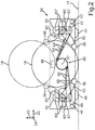
- Fig. 2 two different positions of the respective wheel support arms 36 are sketched in a longitudinal section of the parking robot 20.
- a first position of the respective wheel support arms 36 and a wheel 14 of the motor vehicle 10 is denoted by solid lines, whereas the second position is outlined in each case by means of dashed lines.
- the respective eccentric pulley 62 has a first predetermined pulley radius 63' in a first sub-area and a second predetermined pulley radius 63 in a second sub-area ", the second roller radius 63" being greater than the first roller radius 63 '.
- the eccentric pulley 62 is now oriented such that the shorter first roller radius 63' is arranged parallel to the parking robot vertical direction 22 and
- the rope 64 between the eccentric rope pulley 62 and a corresponding take-up pulley of the central drive unit 66 has a short rope length 65.
- the eccentric pulley 62 In order to move the wheel 14 of the motor vehicle 10 upwards in the upward direction 22 of the parking robot and thus raise it further from the floor 17, the eccentric pulley 62 is rotated by a total of 90 degrees, and then takes as shown with the dashed lines is sketched, a position in which the larger second roller radius 63 ′′ is arranged parallel to the parking robot vertical direction 22.
- the rope length 65 of the rope 64 is lengthened compared to the first described position of the eccentric rope pulley 62 a force for lifting the wheel 14 is increased significantly between the first and the second position, since the corresponding cable length 65 increases and the lever arm length is thus lengthened of the wheel 14 provided by the central drive unit 66.
- the parking robot 20 has, on the one hand, a sensor device 48, which is, for example, a camera or a radar device that is designed to detect the surroundings of the parking robot 20 and to localize obstacles for the parking robot 20 in the detected surroundings.
- the parking robot 20 has an electric drive machine 42, a battery 43 for supplying the electric drive machine 42 with electrical energy, and the two drive wheels 44.
- the parking robot 20 is therefore designed to drive the two drive wheels 44 for moving the parking robot 20 by means of the electric drive machine 42.
- corresponding control commands can be provided by a control device 49.
- This control device 49 can also be designed to provide a travel trajectory for the parking robot 20 within, for example, a predetermined infrastructure environment, such as a parking garage, based on the data collected by the sensor device 48 relating to the surroundings of the parking robot 20 and the obstacles located in the detected surroundings to determine.
- the parking robot 20 also has a communication interface 46, specifically for a communication connection with at least one additional parking robot 20.
- a communication connection with an infrastructure management server, such as a parking garage management server, or with a control robot can be established via the communication interface 46
- the driving trajectory of the parking robot 20 can be sent or received.
- the parking robot 20 can now be operated, for example, in such a way that it first moves autonomously from the outside next to the wheel 14 of the motor vehicle 10 into the receiving position and there lifts the wheel 14 by rotating the respective wheel support arm 36 about the respective axis of rotation 39 in a respective predetermined direction of rotation . If such a procedure takes place, for example, additionally by three further parking robots 20 on the three further wheels 14 of a total of four wheels 14 of the motor vehicle 10, can The motor vehicle 10 can be raised completely from the floor 17 by the total of four parking robots 20.
- the four respective parking robots 20 can then drive in accordance with the respective provided travel trajectories to a predetermined target position, for example a parking space within a parking garage, and set down the motor vehicle 10 there again by rotating the respective wheel support arms 36 in the respective opposite direction of rotation.
- the parking robots 20 can then, for example, drive autonomously to another vehicle in order to also park this vehicle autonomously, for example, at a corresponding target position.
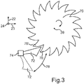
- a safety mechanism for the parking robot 20 is outlined.
- This includes the toothed disk 70, which is coupled to the respective crank element 60 and the respective wheel support arm 36 so that it can rotate about the respective axis of rotation 39.
- the respective toothed pulley 70 is here arranged parallel to a respective rope pulley 62, that is to say in the plane that is spanned by the parking robot vertical direction 22 and the parking robot longitudinal direction 23.
- a surface of the toothed disk 70 is thus arranged perpendicular to the axis of rotation 39.
- the retaining element 74 for the safety wedge 72 of the toothed disk 70 is arranged to the side of the toothed disk 70.
- a position of the safety wedge 72 is sketched with solid lines, in which it is placed against the toothed disk 70 by means of the holding element 74.
- the safety wedge 72 is always in this position when the wheel 14 of the motor vehicle 10 is to be raised by means of the wheel support arm 36 and / or when the wheel 14 is to be held in the raised position.
- the respective toothed disk 70 is rotated about the axis of rotation 39 in the specified direction of rotation, which is sketched here with a small arrow, the safety wedge 72 moves from one tooth 76 to an adjacent tooth 76 'of the toothed disk 70. Due to the sketched shape of the respective teeth 76, 76 ', however, rotation in the opposite direction of rotation about the axis of rotation 39 is blocked.
- the respective teeth 76, 76 ' have two different sides, a flat side and a side that is steeper in comparison therewith.
- the safety wedge 72 is designed to be held at a predetermined distance 78 from the toothed disk 70 by means of the holding element 74 during a respective rotation of the respective wheel support arm 36 about the respective axis of rotation 39 in the opposite direction of rotation.
- This position of the safety wedge 72 is also shown in dashed lines in FIG Fig. 3 outlined. In this position of the safety wedge 72, it does not touch the respective teeth 76, 76 'of the toothed disk 70 and can thus also rotate in the opposite direction of rotation don't block. This position of the safety wedge 72 is selected, for example, when the wheel 14 is set down.
- the example shows how a lifting mechanism with a central drive unit 66 can be implemented with the parking robot 20.
- the prerequisite for this is the eccentric, for example elliptical, rope pulley 62.
- the respective rope pulley 62 can also have more complex shapes, whereby, for example, several respective roller radii 63 ', 63 "are possible and thus a differentiated force profile during one Rotation about the respective axis of rotation 39 is made possible.
Landscapes
- Engineering & Computer Science (AREA)
- Architecture (AREA)
- Mechanical Engineering (AREA)
- Civil Engineering (AREA)
- Structural Engineering (AREA)
- Transportation (AREA)
- Chemical & Material Sciences (AREA)
- Combustion & Propulsion (AREA)
- Manipulator (AREA)
- Vehicle Cleaning, Maintenance, Repair, Refitting, And Outriggers (AREA)
- Automation & Control Theory (AREA)
Claims (10)
- Robot de stationnement (10) pour véhicule automobile (10), le robot de stationnement (20) présentant une paire de bras (36) de soutien de roue montés au moins indirectement au moyen d'un élément de manivelle (60) de manière à pouvoir tourner autour d'un axe de rotation (39) respectif, le robot de stationnement (20) étant conçu pour s'approcher depuis l'extérieur et de manière autonome à côté d'une roue (14) d'un essieu (12) du véhicule automobile (10), dans une position de réception dans laquelle chacun des bras (36) de soutien de roue est disposé parallèlement à l'essieu (12), l'un des bras (36) de soutien de roue étant positionné en avant de la roue (14) dans le sens de la longueur du véhicule et l'autre bras (36) de soutien de roue étant disposé en arrière de la roue (14) dans le sens de la longueur du véhicule, et relever la roue (14) du véhicule automobile (10) en faisant tourner le bras (36) de soutien de roue concerné autour de l'axe de rotation (39) correspondant dans un sens de rotation prédéterminé, les sens de rotation des différents bras (36) de soutien de roue étant opposés l'un à l'autre.
- Robot de stationnement (20) selon la revendication précédente, dans lequel chaque bras (36) de soutien de roue et l'élément de manivelle (60) correspondant sont au moins indirectement accouplés rigidement à une poulie excentrique (62) correspondante dont une première partie présente un premier rayon prédéterminé (63') et une deuxième partie un deuxième rayon prédéterminé (63") plus grand que le premier rayon prédéterminé (63'), un câble respectif (64) étant enroulé autour de la poulie (62) et la poulie (62) étant montée à rotation autour de l'axe de rotation (39), une unité centrale d'entrainement (66) du robot de stationnement (20) étant configurée pour enrouler et dérouler en alternance chaque câble (64) autour de la poulie (62) correspondante.
- Robot de stationnement (20) selon l'une des revendications précédentes, dans lequel un disque denté respectif (70) accouplé à chaque élément de manivelle (60) est monté à rotation autour de l'axe de rotation (39) correspondant, une clavette de sécurité (72) associée à chaque disque denté (70) étant configurée pour, au moyen d'un élément de retenue (74) placé sur le disque denté (70), lors de la rotation du disque denté (70) respectif autour de l'axe de rotation (39) correspondant, être déplacée dans le sens de rotation prédéterminé d'une dent (76) du disque denté (70) à une dent (76') voisine dans le sens de rotation et bloquer la rotation dans le sens de rotation opposé.
- Robot de stationnement (20) selon l'une des revendications précédentes, dans lequel pour abaisser la roue (14) du véhicule automobile (10), la clavette (72) est configurée pour être maintenue au moyen de l'élément de retenue (74) à une distance prédéterminée (78) du disque denté (70) pendant chaque rotation du bras (36) de soutien de roue correspondant dans le sens de rotation opposé autour de l'axe de rotation (39).
- Robot de stationnement (20) selon l'une des revendications précédentes, dans lequel chacun des bras (36) de soutien de roue présente un patin rotatif (38) respectif dont l'axe de rotation (57) est parallèle à l'axe de rotation (39).
- Robot de stationnement (20) selon l'une des revendications précédentes, dans lequel le robot de stationnement comprend un dispositif à capteurs configuré pour saisir l'environnement du robot de stationnement et localiser pour le robot de stationnement des obstacles présents dans l'environnement saisi.
- Robot de stationnement (20) selon l'une des revendications précédentes, dans lequel le robot de stationnement comprend une machine électrique d'entraînement, une batterie qui alimente en électricité la machine d'entraînement ainsi qu'au moins une roue d'entraînement, et est configuré pour entraîner à l'aide de la machine électrique d'entraînement au moins une roue d'entraînement qui fait avancer le robot de stationnement.
- Robot de stationnement (20) selon l'une des revendications précédentes, dans lequel le robot de stationnement comprend une interface de communication qui permet d'établir une liaison de communication avec au moins un autre robot de stationnement.
- Procédé d'utilisation d'un robot de stationnement (20) comprenant une paire de bras (36) de soutien de roue montés au moins indirectement au moyen d'un élément de manivelle (60) de manière à pouvoir tourner autour d'un axe de rotation (39) respectif, le procédé comprenant les étapes suivantes :- approcher depuis l'extérieur et de manière autonome le robot de stationnement (20) à côté d'une roue (14) d'un essieu (12) du véhicule automobile (10) jusque dans une position de réception dans laquelle chacun des bras (36) de soutien de roue est disposé parallèlement à l'essieu (12), l'un des bras (36) de soutien de roue étant positionné en avant de la roue (14) dans le sens de la longueur du véhicule et l'autre bras (36) de soutien de roue étant disposé en arrière de la roue (14) dans le sens de la longueur du véhicule, et- relever la roue (14) du véhicule automobile (10) en faisant tourner le bras (36) de soutien de roue concerné autour de l'axe de rotation (39) correspondant dans des sens de rotation prédéterminés opposés l'un à l'autre.
- Procédé selon la revendication précédente, dans lequel après que trois autres robots de stationnement (20) ont relevé une autre roue (14) d'en tout quatre roues (14) du véhicule automobile (10), les quatre robots de stationnement (20) se déplacent vers une position cible prédéterminée en accord avec chacune des trajectoires de déplacement préparées, pour ensuite abaisser le véhicule (10) en faisant tourner les différents bras (36) de soutien de roue dans leur sens de rotation opposé.
Applications Claiming Priority (1)
| Application Number | Priority Date | Filing Date | Title |
|---|---|---|---|
| DE102018221174.4A DE102018221174A1 (de) | 2018-12-06 | 2018-12-06 | Parkroboter für ein Kraftfahrzeug sowie Verfahren zum Betreiben eines derartigen Parkroboters |
Publications (2)
| Publication Number | Publication Date |
|---|---|
| EP3663487A1 EP3663487A1 (fr) | 2020-06-10 |
| EP3663487B1 true EP3663487B1 (fr) | 2021-07-21 |
Family
ID=68342739
Family Applications (1)
| Application Number | Title | Priority Date | Filing Date |
|---|---|---|---|
| EP19204991.4A Active EP3663487B1 (fr) | 2018-12-06 | 2019-10-24 | Robot de stationnement pour un véhicule automobile ainsi que procédé de fonctionnement d'un tel robot de stationnement |
Country Status (4)
| Country | Link |
|---|---|
| US (1) | US20200180695A1 (fr) |
| EP (1) | EP3663487B1 (fr) |
| CN (1) | CN111287524B (fr) |
| DE (1) | DE102018221174A1 (fr) |
Cited By (1)
| Publication number | Priority date | Publication date | Assignee | Title |
|---|---|---|---|---|
| US20230376046A1 (en) * | 2022-05-18 | 2023-11-23 | Jihyun Yoon | Distributed robot-based object movement system and object movement method using the same |
Families Citing this family (10)
| Publication number | Priority date | Publication date | Assignee | Title |
|---|---|---|---|---|
| DE102018221170B4 (de) * | 2018-12-06 | 2021-01-28 | Volkswagen Aktiengesellschaft | Parkroboter für ein Kraftfahrzeug sowie Verfahren zum Betreiben eines derartigen Parkroboters |
| DE102018221173A1 (de) * | 2018-12-06 | 2020-06-10 | Volkswagen Aktiengesellschaft | Parkroboter für ein Kraftfahrzeug |
| US11643054B2 (en) * | 2019-03-20 | 2023-05-09 | Toyota Motor Engineering & Manufacturing North America, Inc. | Vehicle moving devices and methods for moving a vehicle |
| EP3865355B1 (fr) * | 2020-02-14 | 2025-04-09 | Wheel.me AS | Agencement de transport d'un objet sur une surface |
| CN113756623B (zh) * | 2020-09-15 | 2023-08-04 | 北京京东乾石科技有限公司 | 自动停车搬运系统及方法 |
| CN112282451B (zh) * | 2020-10-18 | 2022-02-22 | 安徽鸿杰威尔停车设备有限公司 | 一种用于立体停车库的汽车升降机及其工作方法 |
| CN114212076A (zh) * | 2021-12-27 | 2022-03-22 | 安徽江淮汽车集团股份有限公司 | 一种基于车载机器人的自动泊车系统 |
| KR20230167506A (ko) * | 2022-06-02 | 2023-12-11 | 에이치엘만도 주식회사 | 차량용 주차 로봇 및 차량 주차 방법 |
| DE102022211486A1 (de) | 2022-10-28 | 2024-05-08 | Robert Bosch Gesellschaft mit beschränkter Haftung | Rangierheber |
| GB2644421A (en) * | 2024-06-26 | 2026-04-15 | Bilwani Farhan | Autonomous valet parking robot AMR |
Family Cites Families (25)
| Publication number | Priority date | Publication date | Assignee | Title |
|---|---|---|---|---|
| US2392830A (en) * | 1943-06-01 | 1946-01-15 | Baum Cleophas Philemon | Airplane lift dolly |
| GB653506A (en) * | 1947-06-03 | 1951-05-16 | Harold Auger | Improvements in power transmission mechanism and the use thereof in mechanical storage equipment |
| US3120196A (en) * | 1961-04-13 | 1964-02-04 | Peter Gilbert | Conveyors for vehicles mounted on wheels |
| US4900215A (en) * | 1988-11-09 | 1990-02-13 | Nowell Charles P | Powered towing dolly for vehicles |
| JP3398222B2 (ja) * | 1994-07-28 | 2003-04-21 | エム・ピー・イー株式会社 | 台車固定装置 |
| JP2007233771A (ja) * | 2006-03-01 | 2007-09-13 | National Institute Of Advanced Industrial & Technology | 自律移動型の車両誘導システムおよび方法 |
| CN1827909B (zh) * | 2006-03-30 | 2010-12-15 | 上海诸光机械有限公司 | 工程用防卷绕钢丝绳的维护保养装置及维护保养方法 |
| US8657305B1 (en) * | 2006-08-17 | 2014-02-25 | Curtis C. Hassell | Self-loading tow dolly |
| US8393431B2 (en) * | 2009-01-17 | 2013-03-12 | Boomerang Systems, Inc. | Omnidirectional drive and steering unit |
| DE102010052850B3 (de) * | 2010-11-29 | 2012-06-06 | Serva Transport Systems Gmbh | Vorrichtung und Verfahren zum automatischen Quereinlagern eines Kraftfahrzeuges in einer Lagereinrichtung |
| JP5752460B2 (ja) * | 2011-03-11 | 2015-07-22 | Ihi運搬機械株式会社 | 物体移動装置 |
| DE102014112269A1 (de) * | 2014-08-27 | 2016-03-03 | Nussbaum Technologies Gmbh | Automatisiertes Parksystem für Fahrzeuge |
| DE102014224099A1 (de) * | 2014-11-26 | 2016-06-02 | Robert Bosch Gmbh | Verfahren und Vorrichtung zum Betreiben von mehreren Fahrzeugen |
| CN104612437B (zh) * | 2015-02-10 | 2017-06-23 | 广州信邦智能装备股份有限公司 | 一种可升降泊车机器人 |
| DE102015202468A1 (de) * | 2015-02-12 | 2016-08-18 | Robert Bosch Gmbh | Verfahren zum Betreiben eines Fahrzeugs |
| DE102015203506A1 (de) * | 2015-02-27 | 2016-09-01 | Siemens Aktiengesellschaft | Automobile Transporteinheit zum Positionieren von Fahrzeugen, Verfahren dafür sowie Parksystem |
| KR101703651B1 (ko) * | 2015-08-13 | 2017-02-08 | 시마텍인터내셔널 주식회사 | 로봇 트롤리 주차 제어방법 및 그 장치 |
| DE102016100730A1 (de) * | 2016-01-18 | 2017-07-20 | Valeo Schalter Und Sensoren Gmbh | Verfahren zum Unterstützen einer autonomen Fahrt eines Kraftfahrzeugs. Steuereinrichtung, Parkassistenzsystem sowie Kraftfahrzeug |
| CN107663963A (zh) * | 2016-07-28 | 2018-02-06 | 深圳力侍技术有限公司 | 一种停车机器人 |
| WO2018026347A1 (fr) * | 2016-08-01 | 2018-02-08 | Ford Global Technologies, Llc | Stationnement incliné |
| CN106584333B (zh) * | 2016-11-29 | 2018-10-16 | 东风设计研究院有限公司 | 接车装置专用抱胎夹持器 |
| DE102016224098B4 (de) | 2016-12-05 | 2021-12-16 | Kuka Deutschland Gmbh | Omnidirektional mobile Kraftfahrzeug-Transportplattform, zugehörige Kraftfahrzeug-Versorgungsstation und Parksystem |
| DE102017206292B4 (de) * | 2017-04-12 | 2019-06-13 | Audi Ag | Verfahren zum Betreiben eines Transportsystems sowie entsprechendes Transportsystem |
| CN207761382U (zh) | 2017-12-18 | 2018-08-24 | 重庆复融科技有限公司 | 用于智能停车场的转运车 |
| CN108266031A (zh) * | 2018-03-28 | 2018-07-10 | 郝瀚 | 一种车辆转移设备及分体协同停车系统 |
-
2018
- 2018-12-06 DE DE102018221174.4A patent/DE102018221174A1/de not_active Withdrawn
-
2019
- 2019-10-24 EP EP19204991.4A patent/EP3663487B1/fr active Active
- 2019-12-04 US US16/702,913 patent/US20200180695A1/en not_active Abandoned
- 2019-12-05 CN CN201911232433.9A patent/CN111287524B/zh active Active
Cited By (2)
| Publication number | Priority date | Publication date | Assignee | Title |
|---|---|---|---|---|
| US20230376046A1 (en) * | 2022-05-18 | 2023-11-23 | Jihyun Yoon | Distributed robot-based object movement system and object movement method using the same |
| US12093057B2 (en) * | 2022-05-18 | 2024-09-17 | Jihyun Yoon | Distributed robot-based object movement system and object movement method using the same |
Also Published As
| Publication number | Publication date |
|---|---|
| CN111287524B (zh) | 2021-09-10 |
| EP3663487A1 (fr) | 2020-06-10 |
| DE102018221174A1 (de) | 2020-06-10 |
| CN111287524A (zh) | 2020-06-16 |
| US20200180695A1 (en) | 2020-06-11 |
Similar Documents
| Publication | Publication Date | Title |
|---|---|---|
| EP3663487A1 (fr) | Robot de stationnement pour un véhicule automobile ainsi que procédé de fonctionnement d'un tel robot de stationnement | |
| EP3663486B1 (fr) | Robot de stationnement pour un véhicule automobile ainsi qu'un procédé de fonctionnement d'un tel robot de stationnement | |
| DE102018221169B4 (de) | Parkroboter für ein Kraftfahrzeug mit wenigstens zwei Radachsen sowie Verfahren zum Betreiben eines derartigen Parkroboters | |
| EP3663488B1 (fr) | Robot de stationnement pour un véhicule automobile | |
| EP3663166B1 (fr) | Système de robot de stationnement pour un véhicule automobile pourvu d'une pluralité de roues ainsi que procédé de fonctionnement d'un tel système de robots de stationnement | |
| EP2614198B1 (fr) | Dispositif et procédé permettant le parcage transversal automatique d'un véhicule à moteur dans un parking | |
| EP3365879B1 (fr) | Procédé et dispositif pour réduire le risque de collision d'un véhicule à moteur avec un objet | |
| DE102018221172B4 (de) | Parkroboter für ein Kraftfahrzeug sowie Verfahren zum Betreiben eines derartigen Parkroboters | |
| WO2017041948A1 (fr) | Procédé et dispositif de fonctionnement d'un parc de stationnement | |
| WO2011001235A1 (fr) | Système dascenseur dun parc de stationnement de véhicules | |
| DE102006053528A1 (de) | Rangiervorrichtung für auf einer Parkfläche abzustellende Fahrzeuge und Parkanlage mit einer Rangiervorrichtung | |
| DE102022113057A1 (de) | Treppensteigvorrichtung | |
| EP3269582A1 (fr) | Véhicule à propulsion électrique ou hybride ne roulant pas sur rails | |
| DE102019212232B4 (de) | Transportvorrichtung für ein Parksystem zum Positionieren eines Kraftfahrzeugs und Verfahren zum Betreiben eines Parksystems | |
| EP3691938A1 (fr) | Véhicule de stationnement et procédé de transport et de stationnement d'un véhicule | |
| DE60011738T2 (de) | Wagen zum Befördern von Fahrzeugen in einem Parkhaus | |
| DE69803777T2 (de) | Fahrzeug für die verlegung von notpisten | |
| DE10253847A1 (de) | Aufnahmeeinrichtung für ein Fahrzeug | |
| DE19621962C2 (de) | Führerhaus für Richtungswechselbetrieb | |
| DE102019202086B3 (de) | Parkroboter zum Transportieren eines geparkten Kraftfahrzeugs sowie Verfahren zum Betreiben eines derartigen Parkroboters | |
| EP2066538B1 (fr) | Portique de lavage et procédé de montage d'un portique de lavage | |
| DE102006022242B4 (de) | Verfahrsystem | |
| DE102017223335A1 (de) | Aufnahmesystem für ein Parkierfahrzeug und Parkierfahrzeug | |
| EP3327231B1 (fr) | Chariot pour élément de paroi coulissante d'une installation de paroi coulissante et installation de paroi coulissante | |
| DE102020204048A1 (de) | Heberoboter zum Einladen und Ausladen eines Rollstuhls in ein/aus einem Fahrzeug und Verfahren zum Betreiben eines Heberoboters |
Legal Events
| Date | Code | Title | Description |
|---|---|---|---|
| PUAI | Public reference made under article 153(3) epc to a published international application that has entered the european phase |
Free format text: ORIGINAL CODE: 0009012 |
|
| STAA | Information on the status of an ep patent application or granted ep patent |
Free format text: STATUS: THE APPLICATION HAS BEEN PUBLISHED |
|
| AK | Designated contracting states |
Kind code of ref document: A1 Designated state(s): AL AT BE BG CH CY CZ DE DK EE ES FI FR GB GR HR HU IE IS IT LI LT LU LV MC MK MT NL NO PL PT RO RS SE SI SK SM TR |
|
| AX | Request for extension of the european patent |
Extension state: BA ME |
|
| STAA | Information on the status of an ep patent application or granted ep patent |
Free format text: STATUS: REQUEST FOR EXAMINATION WAS MADE |
|
| 17P | Request for examination filed |
Effective date: 20201210 |
|
| RBV | Designated contracting states (corrected) |
Designated state(s): AL AT BE BG CH CY CZ DE DK EE ES FI FR GB GR HR HU IE IS IT LI LT LU LV MC MK MT NL NO PL PT RO RS SE SI SK SM TR |
|
| GRAP | Despatch of communication of intention to grant a patent |
Free format text: ORIGINAL CODE: EPIDOSNIGR1 |
|
| STAA | Information on the status of an ep patent application or granted ep patent |
Free format text: STATUS: GRANT OF PATENT IS INTENDED |
|
| INTG | Intention to grant announced |
Effective date: 20210217 |
|
| GRAS | Grant fee paid |
Free format text: ORIGINAL CODE: EPIDOSNIGR3 |
|
| GRAA | (expected) grant |
Free format text: ORIGINAL CODE: 0009210 |
|
| STAA | Information on the status of an ep patent application or granted ep patent |
Free format text: STATUS: THE PATENT HAS BEEN GRANTED |
|
| AK | Designated contracting states |
Kind code of ref document: B1 Designated state(s): AL AT BE BG CH CY CZ DE DK EE ES FI FR GB GR HR HU IE IS IT LI LT LU LV MC MK MT NL NO PL PT RO RS SE SI SK SM TR |
|
| REG | Reference to a national code |
Ref country code: GB Ref legal event code: FG4D Free format text: NOT ENGLISH |
|
| REG | Reference to a national code |
Ref country code: CH Ref legal event code: EP |
|
| REG | Reference to a national code |
Ref country code: DE Ref legal event code: R096 Ref document number: 502019001863 Country of ref document: DE |
|
| REG | Reference to a national code |
Ref country code: AT Ref legal event code: REF Ref document number: 1412751 Country of ref document: AT Kind code of ref document: T Effective date: 20210815 |
|
| REG | Reference to a national code |
Ref country code: IE Ref legal event code: FG4D Free format text: LANGUAGE OF EP DOCUMENT: GERMAN |
|
| REG | Reference to a national code |
Ref country code: LT Ref legal event code: MG9D |
|
| REG | Reference to a national code |
Ref country code: NL Ref legal event code: MP Effective date: 20210721 |
|
| PG25 | Lapsed in a contracting state [announced via postgrant information from national office to epo] |
Ref country code: ES Free format text: LAPSE BECAUSE OF FAILURE TO SUBMIT A TRANSLATION OF THE DESCRIPTION OR TO PAY THE FEE WITHIN THE PRESCRIBED TIME-LIMIT Effective date: 20210721 Ref country code: RS Free format text: LAPSE BECAUSE OF FAILURE TO SUBMIT A TRANSLATION OF THE DESCRIPTION OR TO PAY THE FEE WITHIN THE PRESCRIBED TIME-LIMIT Effective date: 20210721 Ref country code: SE Free format text: LAPSE BECAUSE OF FAILURE TO SUBMIT A TRANSLATION OF THE DESCRIPTION OR TO PAY THE FEE WITHIN THE PRESCRIBED TIME-LIMIT Effective date: 20210721 Ref country code: LT Free format text: LAPSE BECAUSE OF FAILURE TO SUBMIT A TRANSLATION OF THE DESCRIPTION OR TO PAY THE FEE WITHIN THE PRESCRIBED TIME-LIMIT Effective date: 20210721 Ref country code: BG Free format text: LAPSE BECAUSE OF FAILURE TO SUBMIT A TRANSLATION OF THE DESCRIPTION OR TO PAY THE FEE WITHIN THE PRESCRIBED TIME-LIMIT Effective date: 20211021 Ref country code: HR Free format text: LAPSE BECAUSE OF FAILURE TO SUBMIT A TRANSLATION OF THE DESCRIPTION OR TO PAY THE FEE WITHIN THE PRESCRIBED TIME-LIMIT Effective date: 20210721 Ref country code: FI Free format text: LAPSE BECAUSE OF FAILURE TO SUBMIT A TRANSLATION OF THE DESCRIPTION OR TO PAY THE FEE WITHIN THE PRESCRIBED TIME-LIMIT Effective date: 20210721 Ref country code: NO Free format text: LAPSE BECAUSE OF FAILURE TO SUBMIT A TRANSLATION OF THE DESCRIPTION OR TO PAY THE FEE WITHIN THE PRESCRIBED TIME-LIMIT Effective date: 20211021 Ref country code: NL Free format text: LAPSE BECAUSE OF FAILURE TO SUBMIT A TRANSLATION OF THE DESCRIPTION OR TO PAY THE FEE WITHIN THE PRESCRIBED TIME-LIMIT Effective date: 20210721 Ref country code: PT Free format text: LAPSE BECAUSE OF FAILURE TO SUBMIT A TRANSLATION OF THE DESCRIPTION OR TO PAY THE FEE WITHIN THE PRESCRIBED TIME-LIMIT Effective date: 20211122 |
|
| PG25 | Lapsed in a contracting state [announced via postgrant information from national office to epo] |
Ref country code: PL Free format text: LAPSE BECAUSE OF FAILURE TO SUBMIT A TRANSLATION OF THE DESCRIPTION OR TO PAY THE FEE WITHIN THE PRESCRIBED TIME-LIMIT Effective date: 20210721 Ref country code: LV Free format text: LAPSE BECAUSE OF FAILURE TO SUBMIT A TRANSLATION OF THE DESCRIPTION OR TO PAY THE FEE WITHIN THE PRESCRIBED TIME-LIMIT Effective date: 20210721 Ref country code: GR Free format text: LAPSE BECAUSE OF FAILURE TO SUBMIT A TRANSLATION OF THE DESCRIPTION OR TO PAY THE FEE WITHIN THE PRESCRIBED TIME-LIMIT Effective date: 20211022 |
|
| REG | Reference to a national code |
Ref country code: DE Ref legal event code: R097 Ref document number: 502019001863 Country of ref document: DE |
|
| PG25 | Lapsed in a contracting state [announced via postgrant information from national office to epo] |
Ref country code: DK Free format text: LAPSE BECAUSE OF FAILURE TO SUBMIT A TRANSLATION OF THE DESCRIPTION OR TO PAY THE FEE WITHIN THE PRESCRIBED TIME-LIMIT Effective date: 20210721 |
|
| PLBE | No opposition filed within time limit |
Free format text: ORIGINAL CODE: 0009261 |
|
| STAA | Information on the status of an ep patent application or granted ep patent |
Free format text: STATUS: NO OPPOSITION FILED WITHIN TIME LIMIT |
|
| PG25 | Lapsed in a contracting state [announced via postgrant information from national office to epo] |
Ref country code: SM Free format text: LAPSE BECAUSE OF FAILURE TO SUBMIT A TRANSLATION OF THE DESCRIPTION OR TO PAY THE FEE WITHIN THE PRESCRIBED TIME-LIMIT Effective date: 20210721 Ref country code: SK Free format text: LAPSE BECAUSE OF FAILURE TO SUBMIT A TRANSLATION OF THE DESCRIPTION OR TO PAY THE FEE WITHIN THE PRESCRIBED TIME-LIMIT Effective date: 20210721 Ref country code: RO Free format text: LAPSE BECAUSE OF FAILURE TO SUBMIT A TRANSLATION OF THE DESCRIPTION OR TO PAY THE FEE WITHIN THE PRESCRIBED TIME-LIMIT Effective date: 20210721 Ref country code: EE Free format text: LAPSE BECAUSE OF FAILURE TO SUBMIT A TRANSLATION OF THE DESCRIPTION OR TO PAY THE FEE WITHIN THE PRESCRIBED TIME-LIMIT Effective date: 20210721 Ref country code: CZ Free format text: LAPSE BECAUSE OF FAILURE TO SUBMIT A TRANSLATION OF THE DESCRIPTION OR TO PAY THE FEE WITHIN THE PRESCRIBED TIME-LIMIT Effective date: 20210721 Ref country code: AL Free format text: LAPSE BECAUSE OF FAILURE TO SUBMIT A TRANSLATION OF THE DESCRIPTION OR TO PAY THE FEE WITHIN THE PRESCRIBED TIME-LIMIT Effective date: 20210721 |
|
| REG | Reference to a national code |
Ref country code: BE Ref legal event code: MM Effective date: 20211031 |
|
| 26N | No opposition filed |
Effective date: 20220422 |
|
| PG25 | Lapsed in a contracting state [announced via postgrant information from national office to epo] |
Ref country code: MC Free format text: LAPSE BECAUSE OF FAILURE TO SUBMIT A TRANSLATION OF THE DESCRIPTION OR TO PAY THE FEE WITHIN THE PRESCRIBED TIME-LIMIT Effective date: 20210721 |
|
| PG25 | Lapsed in a contracting state [announced via postgrant information from national office to epo] |
Ref country code: LU Free format text: LAPSE BECAUSE OF NON-PAYMENT OF DUE FEES Effective date: 20211024 Ref country code: IT Free format text: LAPSE BECAUSE OF FAILURE TO SUBMIT A TRANSLATION OF THE DESCRIPTION OR TO PAY THE FEE WITHIN THE PRESCRIBED TIME-LIMIT Effective date: 20210721 Ref country code: BE Free format text: LAPSE BECAUSE OF NON-PAYMENT OF DUE FEES Effective date: 20211031 |
|
| PG25 | Lapsed in a contracting state [announced via postgrant information from national office to epo] |
Ref country code: IE Free format text: LAPSE BECAUSE OF NON-PAYMENT OF DUE FEES Effective date: 20211024 |
|
| REG | Reference to a national code |
Ref country code: CH Ref legal event code: PL |
|
| P01 | Opt-out of the competence of the unified patent court (upc) registered |
Effective date: 20230523 |
|
| PG25 | Lapsed in a contracting state [announced via postgrant information from national office to epo] |
Ref country code: CY Free format text: LAPSE BECAUSE OF FAILURE TO SUBMIT A TRANSLATION OF THE DESCRIPTION OR TO PAY THE FEE WITHIN THE PRESCRIBED TIME-LIMIT Effective date: 20210721 |
|
| PG25 | Lapsed in a contracting state [announced via postgrant information from national office to epo] |
Ref country code: LI Free format text: LAPSE BECAUSE OF NON-PAYMENT OF DUE FEES Effective date: 20221031 Ref country code: HU Free format text: LAPSE BECAUSE OF FAILURE TO SUBMIT A TRANSLATION OF THE DESCRIPTION OR TO PAY THE FEE WITHIN THE PRESCRIBED TIME-LIMIT; INVALID AB INITIO Effective date: 20191024 Ref country code: CH Free format text: LAPSE BECAUSE OF NON-PAYMENT OF DUE FEES Effective date: 20221031 |
|
| PG25 | Lapsed in a contracting state [announced via postgrant information from national office to epo] |
Ref country code: MK Free format text: LAPSE BECAUSE OF FAILURE TO SUBMIT A TRANSLATION OF THE DESCRIPTION OR TO PAY THE FEE WITHIN THE PRESCRIBED TIME-LIMIT Effective date: 20210721 |
|
| PG25 | Lapsed in a contracting state [announced via postgrant information from national office to epo] |
Ref country code: TR Free format text: LAPSE BECAUSE OF FAILURE TO SUBMIT A TRANSLATION OF THE DESCRIPTION OR TO PAY THE FEE WITHIN THE PRESCRIBED TIME-LIMIT Effective date: 20210721 |
|
| PG25 | Lapsed in a contracting state [announced via postgrant information from national office to epo] |
Ref country code: MT Free format text: LAPSE BECAUSE OF FAILURE TO SUBMIT A TRANSLATION OF THE DESCRIPTION OR TO PAY THE FEE WITHIN THE PRESCRIBED TIME-LIMIT Effective date: 20210721 |
|
| REG | Reference to a national code |
Ref country code: AT Ref legal event code: MM01 Ref document number: 1412751 Country of ref document: AT Kind code of ref document: T Effective date: 20241024 |
|
| PGFP | Annual fee paid to national office [announced via postgrant information from national office to epo] |
Ref country code: DE Payment date: 20251031 Year of fee payment: 7 |
|
| PGFP | Annual fee paid to national office [announced via postgrant information from national office to epo] |
Ref country code: GB Payment date: 20251021 Year of fee payment: 7 |
|
| PG25 | Lapsed in a contracting state [announced via postgrant information from national office to epo] |
Ref country code: AT Free format text: LAPSE BECAUSE OF NON-PAYMENT OF DUE FEES Effective date: 20241024 |
|
| PGFP | Annual fee paid to national office [announced via postgrant information from national office to epo] |
Ref country code: FR Payment date: 20251027 Year of fee payment: 7 |
|
| PGFP | Annual fee paid to national office [announced via postgrant information from national office to epo] |
Ref country code: AT Payment date: 20260410 Year of fee payment: 5 |