EP3663493A1 - Befestigungsklammer des hebelgestänges zum öffnen eines schlosses - Google Patents
Befestigungsklammer des hebelgestänges zum öffnen eines schlosses Download PDFInfo
- Publication number
- EP3663493A1 EP3663493A1 EP19210203.6A EP19210203A EP3663493A1 EP 3663493 A1 EP3663493 A1 EP 3663493A1 EP 19210203 A EP19210203 A EP 19210203A EP 3663493 A1 EP3663493 A1 EP 3663493A1
- Authority
- EP
- European Patent Office
- Prior art keywords
- clip
- rod
- opening
- opening lever
- lever
- Prior art date
- Legal status (The legal status is an assumption and is not a legal conclusion. Google has not performed a legal analysis and makes no representation as to the accuracy of the status listed.)
- Granted
Links
Images

Classifications
-
- E—FIXED CONSTRUCTIONS
- E05—LOCKS; KEYS; WINDOW OR DOOR FITTINGS; SAFES
- E05B—LOCKS; ACCESSORIES THEREFOR; HANDCUFFS
- E05B79/00—Mounting or connecting vehicle locks or parts thereof
- E05B79/10—Connections between movable lock parts
- E05B79/12—Connections between movable lock parts using connecting rods
- E05B79/16—Connections between movable lock parts using connecting rods characterised by the means for linking the rods to other lock parts, e.g. to levers
Definitions
- the present invention relates to a lock opening lever rod clip. These staples are used to connect a rod to a lock opening lever and therefore to be a real interface between the rod and the lock opening lever. This invention also relates to a mechanism allowing the opening and / or the locking of an opening, and even more particularly of a motor vehicle door as well as the mounting of such a mechanism.
- the device is characterized in that it comprises an element intended to maintain the upper end of the connection in a position relative to the cavity forming a guide rail, the pull comprising a part projecting in the structure of the door to through the bottom of the cavity forming a guide rail and comprising at least one bore in which is engaged the upper end of the linkage.
- the present invention aims to remedy these drawbacks by providing a clip for an interface between a rod and a lever for opening a lock for a vehicle window, characterized in that the clip comprises a cradle configured to receive a first branch of the rod and an orifice configured to be crossed by a second branch of said rod, the cradle having a substantially cylindrical casing intended to hold said first branch of the rod and an opening from which walls extend flaring from the opening and moving away from each other.
- This clip ensures the mechanical connection in translation of opening and / or locking of an opening with the advantages of optimal kinematics of the clip solution of the 1 ⁇ 4 turn type and of not generating torque on the rod.
- the cradle extends along a longitudinal axis, the clip being characterized in that, in an assembled position, the longitudinal axis of the cradle is configured to be substantially parallel to an axis of rotation A of said opening lever.
- the walls extend in a direction substantially opposite to the opening of the cradle.
- This funnel-shaped configuration allows the rod to be received by the clip.
- the clip comprises a base provided with fixing means to ensure its removable fixing with the opening lever, the base being for example formed at least by the outer periphery of the cradle.
- the fixing means comprise a groove arranged on each external face of said base configured to be parallel to the direction of introduction of said clip into said opening lever and configured to receive in sliding connection a tongue opening lever.
- This configuration allows an effective connection between the clip and the opening lever.
- the anti-noise means comprise a recess, said recess being delimited in part by an elastic wall having a surface of rounded shape configured to be in contact and elastically under stress with the rod in the assembled position.
- the anti-noise means comprise a lug located in at least one of the grooves, preferably each of the grooves, of the clip.
- the clip and the opening lever form a single piece.
- the invention also relates to an assembly comprising a clip and an opening lever.
- the invention also relates to an opening mechanism comprising a rod intended to be actuated by a handle such as a handle of a vehicle leaf, the rod being linked to an opening lever of a lock of the leaf , the opening mechanism being characterized in that it comprises a clip forming an interface between said rod and the opening lever.
- the clip according to the invention is in one of the following plastics: polyoxymethylene, polyacetal, or polyamide.
- plastics polyoxymethylene, polyacetal, or polyamide.
- This method allows faster mounting and less difficulty of such a device.
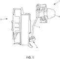
- the figure 1 shows the mounting of a handle 1 connected to a lock 2 via a rod 3.
- the rod 3 is integral with the handle 1 via one of its ends and solidiaire of the lock 2 via its other end.
- an opening lever 4 forming an integral part of the lock 2, which receives the rod 3.
- the gripping element 5 When an attempt is made to open a door of a motor vehicle, for example, by a user, that -this grips the handle 1 by the gripping element 5, which causes a movement of the rod 3, which itself drives the opening lever 4 of the lock 2 in movement and thus freeing the opening of the door of motor vehicle.
- a clip for holding the rod 3 on the opening lever 4 of the lock 2 is detailed in the following figures. Thus, this will allow us to understand the different advantages provided by it.
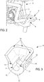
- the figure 2 shows a rod 3 inserted into an opening lever 4 for lock 2.
- the opening lever 4 has a recess 6 receiving the rod 3.
- the rod 3 can have several bends 7.
- the insertion of the rod 3 in the opening lever 4 of the lock 2 is made at a bend in the rod 3.
- the opening lever 4 has a bent angle 8 allowing the reception of the rod 3 and its imprisonment in the opening lever 4. This results in the fact that the forces undergone by the rod 3, for example when opening or locking a motor vehicle opening, are taken up directly by the lever. opening 4.
- a clip 9, described in the following figure, is configured to be inserted in the recess 6 .
- the figure 3 shows a clip 9.
- a first noise reduction means 13 and a third noise reduction means 16 the latter is disposed on each groove 22.
- This clip comprises two grooves 22, arranged in the extension of the cylindrical shape of the clip 9, at the base of the clip 9. These grooves 22 are configured to receive a corresponding tongue 23 disposed on the opening lever 4.
- These anti-noise means 13 and 16 are also fixing means, this fixing being preferably elastic so as to limit the emission of parasitic noise due to the vibrations of a vehicle for example.
- a funnel shape produced by walls 19 forming a U, makes it easier to assemble a rod 3 in the clip 9.
- these walls 19 allow the rod 3 to be guided during its insertion into this clip 9, clip 9 already being clipped to the opening lever 4.
- the funnel shape is produced by walls 19 forming a U and extending beyond the cradle-shaped opening. The walls move away from each other. Indeed, these walls 19 flare from an opening forming the cradle 11. It is understood by walls 19 flaring from the opening, walls 19 which move away from one another towards the outside, that is to say in the direction opposite to the opening.
- a chamfer 10 is produced following the walls 19 on the inner periphery of the clip 9 then comes a cradle 11 having a substantially cylindrical envelope allowing the reception of a first branch 24 of the rod 3.
- An orifice 21 is produced in the cradle 11 thus allowing the passage of a second branch 25 of the rod 3. More specifically, the first branch 24 of the rod 3 cooperates with the cradle 11 of the clip 9 and the second branch 25 of the rod 3 cooperates with the hole 21 of the clip 9.
- This substantially cylindrical envelope is intended to hold in engagement, preferably elastically, the first branch 24 of the rod 3.
- this cylindrical envelope is open on one side and closed on the other, thus forming a U.
- the figure 4 shows a clip 9 and a lock opening lever 4 2.
- the clip 9 has a shape of cradle 11, substantially cylindrical, configured to fit into the recess 6 configured to receive the clip 9.
- the clip 9 has a specific bore. Indeed, chamfers 10 on either side of the interior surface of the clip 9 are present and then follows a cradle 11 substantially of cylindrical shape.
- the clip 9 has, at its lateral outer surfaces, a groove 22 configured to be inserted in a corresponding tongue 23, located on the opening lever 4 on either side of the inner surface parallel to the direction introduction of the clip 9 on the opening lever 4, the latter being materialized by an arrow.
- Each groove 22 is parallel to the longitudinal axis X of the cradle 11.
- a clip 12 is located upstream of the clip 9, therefore being in the direction of the direction of insertion of the clip 9 into the opening lever 4.
- This clip 12 has the shape of a hook arranged in one direction perpendicular to the direction of insertion of the clip 9 into the opening lever 4.
- the clip 12 by means of its hook, clips into place the outer surface of the opening lever 4 opposite the direction of insertion of the clip 9 into the opening lever 4.
- This clip 12 is configured to clip the clip 9 onto the opening lever 4 by a movement single translative. This clipping mode allows a simpler and faster assembly of the mechanism.
- the clip 9 also includes three anti-noise means, the first anti-noise means 13 is a lug located downstream of the clip 9 on its outer surface, perpendicular to the direction of introduction of the clip 9 into the opening lever 4 and configured to come into contact with the outer surface of the bent element 8 of the opening lever 4 perpendicular to the direction of insertion of the clip 9 on the opening lever 4.
- the first anti-noise means 13 has an angle of inclination in the direction of the direction of insertion of the clip 9 into the opening lever 4 allowing the clip 9 to be effectively held on the opening lever 4.
- the second noise reduction means 14 is arranged opposite the first noise reduction means 13. It is the surface of the second noise reduction means 14 opposite the first noise reduction means 13 which is configured to be in contact with the rod 3. In fact, this surface is of rounded shape, allowing the plating of the rod 3 on the clip 9.
- the second anti-noise means 14 has a recess 15 allowing it to exert a spring effect.
- the third anti-noise means 16 is also a lug located on each groove 22 and configured to be in contact with the corresponding tongue 23 of the opening lever 4.
- the figure 5 shows the opening lever 4 into which the clip 9 is inserted by clipping.
- the clip 12 via its hook, allows the clip 9 to be secured to the opening lever 4, in combination with the anti-noise means 13.
- the clip 12 is therefore also a fixing means which is preferably elastic. The same applies to the tongues 23 of the opening lever 4 inserted in the corresponding grooves 22 of the clip 9.
- the noise canceling means 13 is in contact with the opening lever 4, thus avoiding the noise of the clip 9 on the opening lever 4 during driving.
- the noise canceling means 14 is in contact with the rod 3 and has a recess 15 making it possible to avoid any noise from the rod 3 on the clip 9 during rolling.
- the third anti-noise means 16 is in contact with the corresponding tongue 23 of the opening lever 4 making it possible to avoid any noise from the rod 3 on the clip 9 during rolling.
- a rod 3 is inserted in the clip 9 and therefore also in the opening lever 4 by their joining.
- the insertion of the rod 3 into the clip 9 is facilitated by the walls 19 of the clip 9.
- the rod 3 is therefore trapped in the opening lever 4 by means of the clip 9 by clipping of the clip 9 on the opening lever 4 but also by the anti-noise means. By this imprisonment, the forces undergone by the rod 3 are taken up directly by the opening lever 4.
- first branch 24 which is received in the cradle 11 of substantially cylindrical shape of the clip 9.
- a first branch 24 is received in the cradle 11 of substantially cylindrical shape and a second branch 25 passes through the clip 9 through an orifice 21.
- a bent part 7 makes the transition between the first branch 24 received in the cradle 11 of substantially cylindrical shape and the second branch 25 passing through the orifice 21.
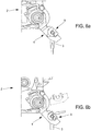
- FIGS. 6a and 6b show an opening lever 4 of a lock 2.
- a clip 9 is inserted by clipping into the opening lever 4.
- a rod 3 is inserted into the clip 9, itself inserted into the opening lever 4 It can be seen that the opening lever 4 is mounted in rotation along an axis A on the lock 2 with compatibility of an angular amplitude close to 180 °.
- the cradle 11 of the clip 9 is parallel to the axis of rotation A of the opening lever 4.
- the elbow 7 of the rod 3 fitting into the clip 9 is supported on the radius of the clip 9 Then it is the clip 9 which presses on the radius of the opening lever 4.
- a self-locking is provided in the event of overtravel in order to reduce the separation of the rod 3 / clip 9 when the rod 3 rises faster than the opening lever 4.
- the opening lever 4 when a user decides to open a vehicle window, for example, the opening lever 4 is set in motion along the axis A by the force exerted on the rod 3 when gripping the gripping element 5 of handle 1 by a user.
- the configuration of the clip 9 traps the rod 3. This is materialized by an arrow showing that the rod 3 cannot move in the direction of the arrow in the event of overshoot of the rod 3.
- the arrow shows the configuration of the clip 9, substantially cylindrical and comprising walls forming a U. It is this configuration which allows self-locking in overtravel of the rod 3.
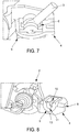
- the figure 7 shows an opening lever 4 in which a rod 3 is inserted by means of a clip 9.
- a rod 3 is inserted by means of a clip 9.
- the recess 6 is not completely filled by the rod 3 due to the conformation of the clip 9 and especially at its angles. Indeed, the angles of the clip 9 receiving the rod 3 does not interfere with the rod 3 so that total movement of the rod 3 is possible and therefore leaves the freedom of rotation of this rod 3.
- the cradle 11 has a longitudinal axis X around which the rod 3 pivots when it is in the assembled position, the longitudinal axis X of the cradle 11 being located parallel to the axis of rotation A of the opening lever 4.
- the cradle 11 forms a pivot connection with the first branch 24 of the rod 3.
- the figure 8 shows a lock opening lever 4 2 in which the clip 9 is integrated in the opening lever 4.
- the opening lever 4 and the clip 9 only form one and the same room.
- the chamfers 10 produced on the periphery of the internal face of the clip 9 have therefore merged with the surface of the opening lever 4 parallel to the direction of introduction of the clip 9 into the opening lever 4 as shown in the figure 4 .
- the surface of the cradle 11 of substantially cylindrical shape receiving the first anti-noise means 13 has merged with the surface of the opening lever perpendicular to the direction of insertion of the clip 9 into the opening lever 4 as shown in the figure 4 .
- This embodiment allows an even faster and simpler assembly.
- the clip 9 is preferably in one of the following plastics: polyoxymethylene, polyacetal (loaded with or not loaded), or even with polyamide (loaded or not, and its variants, PA6, PA66, PA612, etc.) ).
- the plastics mentioned contribute to resist the efforts on the one hand, limit the contact friction and also to limit the noise.
Landscapes
- Lock And Its Accessories (AREA)
- Clamps And Clips (AREA)
Applications Claiming Priority (1)
| Application Number | Priority Date | Filing Date | Title |
|---|---|---|---|
| FR1872314A FR3089242B1 (fr) | 2018-12-04 | 2018-12-04 | Agrafe de tringle de levier d’ouverture de serrure |
Publications (2)
| Publication Number | Publication Date |
|---|---|
| EP3663493A1 true EP3663493A1 (de) | 2020-06-10 |
| EP3663493B1 EP3663493B1 (de) | 2021-05-12 |
Family
ID=67742467
Family Applications (1)
| Application Number | Title | Priority Date | Filing Date |
|---|---|---|---|
| EP19210203.6A Active EP3663493B1 (de) | 2018-12-04 | 2019-11-19 | Befestigungsklammer des hebelgestänges zum öffnen eines schlosses |
Country Status (2)
| Country | Link |
|---|---|
| EP (1) | EP3663493B1 (de) |
| FR (1) | FR3089242B1 (de) |
Families Citing this family (3)
| Publication number | Priority date | Publication date | Assignee | Title |
|---|---|---|---|---|
| FR3134838B1 (fr) * | 2022-04-20 | 2024-07-05 | Renault | Dispositif de commande destiné à équiper un ouvrant d'un véhicule automobile |
| JP2024068756A (ja) | 2022-11-09 | 2024-05-21 | 三井金属アクト株式会社 | 車両用ドアラッチ装置 |
| US20250109619A1 (en) * | 2023-09-29 | 2025-04-03 | Rvlock & Co, Llc | Recreational vehicle door latch engagement systems |
Citations (3)
| Publication number | Priority date | Publication date | Assignee | Title |
|---|---|---|---|---|
| FR2613754A1 (fr) | 1987-04-13 | 1988-10-14 | Peugeot | Dispositif a tirette de frise de commande du verrouillage ou deverrouillage d'une porte d'un vehicule automobile |
| JPH0336508U (de) * | 1989-08-22 | 1991-04-09 | ||
| DE102013208652A1 (de) * | 2013-05-10 | 2014-11-13 | Kiekert Ag | Befestigungselement zur Anbindung von Übertragungsmitteln an ein Hebelelement |
-
2018
- 2018-12-04 FR FR1872314A patent/FR3089242B1/fr active Active
-
2019
- 2019-11-19 EP EP19210203.6A patent/EP3663493B1/de active Active
Patent Citations (3)
| Publication number | Priority date | Publication date | Assignee | Title |
|---|---|---|---|---|
| FR2613754A1 (fr) | 1987-04-13 | 1988-10-14 | Peugeot | Dispositif a tirette de frise de commande du verrouillage ou deverrouillage d'une porte d'un vehicule automobile |
| JPH0336508U (de) * | 1989-08-22 | 1991-04-09 | ||
| DE102013208652A1 (de) * | 2013-05-10 | 2014-11-13 | Kiekert Ag | Befestigungselement zur Anbindung von Übertragungsmitteln an ein Hebelelement |
Also Published As
| Publication number | Publication date |
|---|---|
| FR3089242B1 (fr) | 2021-03-19 |
| EP3663493B1 (de) | 2021-05-12 |
| FR3089242A1 (fr) | 2020-06-05 |
Similar Documents
| Publication | Publication Date | Title |
|---|---|---|
| EP3663493B1 (de) | Befestigungsklammer des hebelgestänges zum öffnen eines schlosses | |
| FR2732073A1 (fr) | Dispositif d'etranglement pour moteur a combustion interne et procede de realisation | |
| WO2004089707A1 (fr) | Procede et agencement pour l’assemblage d’un dispositif d’essuie-glace sur un vehicule automobile | |
| EP1390241B1 (de) | Befestigung eines zubehörteils auf ein kraftfahrzeug | |
| FR3084709A1 (fr) | Accouplement en rotation | |
| FR2478718A1 (fr) | Dispositif a reglage automatique pour le blocage, en position fermee, d'une porte coulissante d'un vehicule automobile | |
| EP2172662B1 (de) | Anordnung zur Befestigung eines ein Kabel aufnehmenden Endstücks in einer Öffnung einer Trägerplatte | |
| FR3039617B1 (fr) | Boitier de transmission et module de transmission equipe d'un tel boitier | |
| FR2733786A1 (fr) | Dispositif de blocage pour fenetres, portes ou analogues | |
| FR2940198A1 (fr) | Tete pour tubulure de remplissage en carburant diesel d'un reservoir de vehicule | |
| FR2966546A1 (fr) | Vanne d'isolement commandee a etancheite renforcee | |
| FR2927644A1 (fr) | Pene demi-tour a organe de contact | |
| FR2830894A1 (fr) | Leve-vitre avec blocage de curseur et procede d'assemblage correspondant | |
| EP0597764B1 (de) | Fensterheber für ein Kraftfahrzeug | |
| FR2791742A1 (fr) | Dispositif de fixation rapide d'une bague dans une echancrure d'une piece support | |
| FR2626822A1 (fr) | Butee elastique notamment pour un element de carrosserie de vehicule automobile, et ouvrant de vehicule automobile equipe d'au moins une butee | |
| EP1908967B1 (de) | Vorrichtung zum Befestigen eines Kabels auf einer Halteplatine | |
| EP1000786A1 (de) | Heizungs-Klimaanlage und/oder Klimaanlage mit ein oder mehreren Klappteilen durch eine Steuervorrichtung gesteuert | |
| EP4239149B1 (de) | Betätigungsvorrichtung für verschiedene arten von getrieben für türschloss | |
| FR2606860A1 (fr) | Mecanisme support d'un organe dont on desire regler la position par rapport a un axe | |
| FR2622245A1 (fr) | Dispositif de fermeture d'imposte ou analogue | |
| EP0686780B1 (de) | Anschlussteil für Betätigungskabel | |
| FR3026424A1 (de) | ||
| FR2843429A1 (fr) | Dispositif de commande d'un module formant mecanisme de serrure | |
| FR3067782B1 (fr) | Procede d’assemblage de guides de chaine de distribution de moteur et systeme de guidage d’une chaine de distribution |
Legal Events
| Date | Code | Title | Description |
|---|---|---|---|
| PUAI | Public reference made under article 153(3) epc to a published international application that has entered the european phase |
Free format text: ORIGINAL CODE: 0009012 |
|
| STAA | Information on the status of an ep patent application or granted ep patent |
Free format text: STATUS: THE APPLICATION HAS BEEN PUBLISHED |
|
| AK | Designated contracting states |
Kind code of ref document: A1 Designated state(s): AL AT BE BG CH CY CZ DE DK EE ES FI FR GB GR HR HU IE IS IT LI LT LU LV MC MK MT NL NO PL PT RO RS SE SI SK SM TR |
|
| AX | Request for extension of the european patent |
Extension state: BA ME |
|
| STAA | Information on the status of an ep patent application or granted ep patent |
Free format text: STATUS: REQUEST FOR EXAMINATION WAS MADE |
|
| 17P | Request for examination filed |
Effective date: 20201026 |
|
| RBV | Designated contracting states (corrected) |
Designated state(s): AL AT BE BG CH CY CZ DE DK EE ES FI FR GB GR HR HU IE IS IT LI LT LU LV MC MK MT NL NO PL PT RO RS SE SI SK SM TR |
|
| GRAP | Despatch of communication of intention to grant a patent |
Free format text: ORIGINAL CODE: EPIDOSNIGR1 |
|
| STAA | Information on the status of an ep patent application or granted ep patent |
Free format text: STATUS: GRANT OF PATENT IS INTENDED |
|
| INTG | Intention to grant announced |
Effective date: 20201209 |
|
| GRAS | Grant fee paid |
Free format text: ORIGINAL CODE: EPIDOSNIGR3 |
|
| GRAA | (expected) grant |
Free format text: ORIGINAL CODE: 0009210 |
|
| STAA | Information on the status of an ep patent application or granted ep patent |
Free format text: STATUS: THE PATENT HAS BEEN GRANTED |
|
| AK | Designated contracting states |
Kind code of ref document: B1 Designated state(s): AL AT BE BG CH CY CZ DE DK EE ES FI FR GB GR HR HU IE IS IT LI LT LU LV MC MK MT NL NO PL PT RO RS SE SI SK SM TR |
|
| REG | Reference to a national code |
Ref country code: GB Ref legal event code: FG4D Free format text: NOT ENGLISH |
|
| REG | Reference to a national code |
Ref country code: CH Ref legal event code: EP |
|
| REG | Reference to a national code |
Ref country code: DE Ref legal event code: R096 Ref document number: 602019004590 Country of ref document: DE |
|
| REG | Reference to a national code |
Ref country code: IE Ref legal event code: FG4D Free format text: LANGUAGE OF EP DOCUMENT: FRENCH |
|
| REG | Reference to a national code |
Ref country code: AT Ref legal event code: REF Ref document number: 1392273 Country of ref document: AT Kind code of ref document: T Effective date: 20210615 |
|
| REG | Reference to a national code |
Ref country code: LT Ref legal event code: MG9D |
|
| REG | Reference to a national code |
Ref country code: AT Ref legal event code: MK05 Ref document number: 1392273 Country of ref document: AT Kind code of ref document: T Effective date: 20210512 |
|
| REG | Reference to a national code |
Ref country code: NL Ref legal event code: MP Effective date: 20210512 |
|
| PG25 | Lapsed in a contracting state [announced via postgrant information from national office to epo] |
Ref country code: HR Free format text: LAPSE BECAUSE OF FAILURE TO SUBMIT A TRANSLATION OF THE DESCRIPTION OR TO PAY THE FEE WITHIN THE PRESCRIBED TIME-LIMIT Effective date: 20210512 Ref country code: LT Free format text: LAPSE BECAUSE OF FAILURE TO SUBMIT A TRANSLATION OF THE DESCRIPTION OR TO PAY THE FEE WITHIN THE PRESCRIBED TIME-LIMIT Effective date: 20210512 Ref country code: FI Free format text: LAPSE BECAUSE OF FAILURE TO SUBMIT A TRANSLATION OF THE DESCRIPTION OR TO PAY THE FEE WITHIN THE PRESCRIBED TIME-LIMIT Effective date: 20210512 Ref country code: AT Free format text: LAPSE BECAUSE OF FAILURE TO SUBMIT A TRANSLATION OF THE DESCRIPTION OR TO PAY THE FEE WITHIN THE PRESCRIBED TIME-LIMIT Effective date: 20210512 Ref country code: BG Free format text: LAPSE BECAUSE OF FAILURE TO SUBMIT A TRANSLATION OF THE DESCRIPTION OR TO PAY THE FEE WITHIN THE PRESCRIBED TIME-LIMIT Effective date: 20210812 |
|
| PG25 | Lapsed in a contracting state [announced via postgrant information from national office to epo] |
Ref country code: SE Free format text: LAPSE BECAUSE OF FAILURE TO SUBMIT A TRANSLATION OF THE DESCRIPTION OR TO PAY THE FEE WITHIN THE PRESCRIBED TIME-LIMIT Effective date: 20210512 Ref country code: PT Free format text: LAPSE BECAUSE OF FAILURE TO SUBMIT A TRANSLATION OF THE DESCRIPTION OR TO PAY THE FEE WITHIN THE PRESCRIBED TIME-LIMIT Effective date: 20210913 Ref country code: RS Free format text: LAPSE BECAUSE OF FAILURE TO SUBMIT A TRANSLATION OF THE DESCRIPTION OR TO PAY THE FEE WITHIN THE PRESCRIBED TIME-LIMIT Effective date: 20210512 Ref country code: NO Free format text: LAPSE BECAUSE OF FAILURE TO SUBMIT A TRANSLATION OF THE DESCRIPTION OR TO PAY THE FEE WITHIN THE PRESCRIBED TIME-LIMIT Effective date: 20210812 Ref country code: PL Free format text: LAPSE BECAUSE OF FAILURE TO SUBMIT A TRANSLATION OF THE DESCRIPTION OR TO PAY THE FEE WITHIN THE PRESCRIBED TIME-LIMIT Effective date: 20210512 Ref country code: LV Free format text: LAPSE BECAUSE OF FAILURE TO SUBMIT A TRANSLATION OF THE DESCRIPTION OR TO PAY THE FEE WITHIN THE PRESCRIBED TIME-LIMIT Effective date: 20210512 Ref country code: GR Free format text: LAPSE BECAUSE OF FAILURE TO SUBMIT A TRANSLATION OF THE DESCRIPTION OR TO PAY THE FEE WITHIN THE PRESCRIBED TIME-LIMIT Effective date: 20210813 Ref country code: IS Free format text: LAPSE BECAUSE OF FAILURE TO SUBMIT A TRANSLATION OF THE DESCRIPTION OR TO PAY THE FEE WITHIN THE PRESCRIBED TIME-LIMIT Effective date: 20210912 |
|
| PG25 | Lapsed in a contracting state [announced via postgrant information from national office to epo] |
Ref country code: NL Free format text: LAPSE BECAUSE OF FAILURE TO SUBMIT A TRANSLATION OF THE DESCRIPTION OR TO PAY THE FEE WITHIN THE PRESCRIBED TIME-LIMIT Effective date: 20210512 |
|
| PG25 | Lapsed in a contracting state [announced via postgrant information from national office to epo] |
Ref country code: CZ Free format text: LAPSE BECAUSE OF FAILURE TO SUBMIT A TRANSLATION OF THE DESCRIPTION OR TO PAY THE FEE WITHIN THE PRESCRIBED TIME-LIMIT Effective date: 20210512 Ref country code: DK Free format text: LAPSE BECAUSE OF FAILURE TO SUBMIT A TRANSLATION OF THE DESCRIPTION OR TO PAY THE FEE WITHIN THE PRESCRIBED TIME-LIMIT Effective date: 20210512 Ref country code: RO Free format text: LAPSE BECAUSE OF FAILURE TO SUBMIT A TRANSLATION OF THE DESCRIPTION OR TO PAY THE FEE WITHIN THE PRESCRIBED TIME-LIMIT Effective date: 20210512 Ref country code: SM Free format text: LAPSE BECAUSE OF FAILURE TO SUBMIT A TRANSLATION OF THE DESCRIPTION OR TO PAY THE FEE WITHIN THE PRESCRIBED TIME-LIMIT Effective date: 20210512 Ref country code: SK Free format text: LAPSE BECAUSE OF FAILURE TO SUBMIT A TRANSLATION OF THE DESCRIPTION OR TO PAY THE FEE WITHIN THE PRESCRIBED TIME-LIMIT Effective date: 20210512 Ref country code: ES Free format text: LAPSE BECAUSE OF FAILURE TO SUBMIT A TRANSLATION OF THE DESCRIPTION OR TO PAY THE FEE WITHIN THE PRESCRIBED TIME-LIMIT Effective date: 20210512 Ref country code: EE Free format text: LAPSE BECAUSE OF FAILURE TO SUBMIT A TRANSLATION OF THE DESCRIPTION OR TO PAY THE FEE WITHIN THE PRESCRIBED TIME-LIMIT Effective date: 20210512 |
|
| REG | Reference to a national code |
Ref country code: DE Ref legal event code: R097 Ref document number: 602019004590 Country of ref document: DE |
|
| PLBE | No opposition filed within time limit |
Free format text: ORIGINAL CODE: 0009261 |
|
| STAA | Information on the status of an ep patent application or granted ep patent |
Free format text: STATUS: NO OPPOSITION FILED WITHIN TIME LIMIT |
|
| 26N | No opposition filed |
Effective date: 20220215 |
|
| PG25 | Lapsed in a contracting state [announced via postgrant information from national office to epo] |
Ref country code: IS Free format text: LAPSE BECAUSE OF FAILURE TO SUBMIT A TRANSLATION OF THE DESCRIPTION OR TO PAY THE FEE WITHIN THE PRESCRIBED TIME-LIMIT Effective date: 20210912 Ref country code: AL Free format text: LAPSE BECAUSE OF FAILURE TO SUBMIT A TRANSLATION OF THE DESCRIPTION OR TO PAY THE FEE WITHIN THE PRESCRIBED TIME-LIMIT Effective date: 20210512 |
|
| PG25 | Lapsed in a contracting state [announced via postgrant information from national office to epo] |
Ref country code: MC Free format text: LAPSE BECAUSE OF FAILURE TO SUBMIT A TRANSLATION OF THE DESCRIPTION OR TO PAY THE FEE WITHIN THE PRESCRIBED TIME-LIMIT Effective date: 20210512 |
|
| PG25 | Lapsed in a contracting state [announced via postgrant information from national office to epo] |
Ref country code: LU Free format text: LAPSE BECAUSE OF NON-PAYMENT OF DUE FEES Effective date: 20211119 Ref country code: IT Free format text: LAPSE BECAUSE OF FAILURE TO SUBMIT A TRANSLATION OF THE DESCRIPTION OR TO PAY THE FEE WITHIN THE PRESCRIBED TIME-LIMIT Effective date: 20210512 Ref country code: BE Free format text: LAPSE BECAUSE OF NON-PAYMENT OF DUE FEES Effective date: 20211130 |
|
| REG | Reference to a national code |
Ref country code: BE Ref legal event code: MM Effective date: 20211130 |
|
| PG25 | Lapsed in a contracting state [announced via postgrant information from national office to epo] |
Ref country code: IE Free format text: LAPSE BECAUSE OF NON-PAYMENT OF DUE FEES Effective date: 20211119 |
|
| PG25 | Lapsed in a contracting state [announced via postgrant information from national office to epo] |
Ref country code: FR Free format text: LAPSE BECAUSE OF NON-PAYMENT OF DUE FEES Effective date: 20211130 |
|
| PG25 | Lapsed in a contracting state [announced via postgrant information from national office to epo] |
Ref country code: CY Free format text: LAPSE BECAUSE OF FAILURE TO SUBMIT A TRANSLATION OF THE DESCRIPTION OR TO PAY THE FEE WITHIN THE PRESCRIBED TIME-LIMIT Effective date: 20210512 |
|
| REG | Reference to a national code |
Ref country code: CH Ref legal event code: PL |
|
| PG25 | Lapsed in a contracting state [announced via postgrant information from national office to epo] |
Ref country code: LI Free format text: LAPSE BECAUSE OF NON-PAYMENT OF DUE FEES Effective date: 20221130 Ref country code: HU Free format text: LAPSE BECAUSE OF FAILURE TO SUBMIT A TRANSLATION OF THE DESCRIPTION OR TO PAY THE FEE WITHIN THE PRESCRIBED TIME-LIMIT; INVALID AB INITIO Effective date: 20191119 Ref country code: CH Free format text: LAPSE BECAUSE OF NON-PAYMENT OF DUE FEES Effective date: 20221130 |
|
| PG25 | Lapsed in a contracting state [announced via postgrant information from national office to epo] |
Ref country code: MK Free format text: LAPSE BECAUSE OF FAILURE TO SUBMIT A TRANSLATION OF THE DESCRIPTION OR TO PAY THE FEE WITHIN THE PRESCRIBED TIME-LIMIT Effective date: 20210512 |
|
| GBPC | Gb: european patent ceased through non-payment of renewal fee |
Effective date: 20231119 |
|
| PG25 | Lapsed in a contracting state [announced via postgrant information from national office to epo] |
Ref country code: MT Free format text: LAPSE BECAUSE OF FAILURE TO SUBMIT A TRANSLATION OF THE DESCRIPTION OR TO PAY THE FEE WITHIN THE PRESCRIBED TIME-LIMIT Effective date: 20210512 |
|
| PG25 | Lapsed in a contracting state [announced via postgrant information from national office to epo] |
Ref country code: GB Free format text: LAPSE BECAUSE OF NON-PAYMENT OF DUE FEES Effective date: 20231119 |
|
| PG25 | Lapsed in a contracting state [announced via postgrant information from national office to epo] |
Ref country code: GB Free format text: LAPSE BECAUSE OF NON-PAYMENT OF DUE FEES Effective date: 20231119 |
|
| PG25 | Lapsed in a contracting state [announced via postgrant information from national office to epo] |
Ref country code: TR Free format text: LAPSE BECAUSE OF FAILURE TO SUBMIT A TRANSLATION OF THE DESCRIPTION OR TO PAY THE FEE WITHIN THE PRESCRIBED TIME-LIMIT Effective date: 20210512 |
|
| PGFP | Annual fee paid to national office [announced via postgrant information from national office to epo] |
Ref country code: DE Payment date: 20251117 Year of fee payment: 7 |