EP3663513B1 - Cutter head for mining machine - Google Patents
Cutter head for mining machine Download PDFInfo
- Publication number
- EP3663513B1 EP3663513B1 EP19218675.7A EP19218675A EP3663513B1 EP 3663513 B1 EP3663513 B1 EP 3663513B1 EP 19218675 A EP19218675 A EP 19218675A EP 3663513 B1 EP3663513 B1 EP 3663513B1
- Authority
- EP
- European Patent Office
- Prior art keywords
- cutting
- cutter head
- mass
- rock
- cutting bit
- Prior art date
- Legal status (The legal status is an assumption and is not a legal conclusion. Google has not performed a legal analysis and makes no representation as to the accuracy of the status listed.)
- Active
Links
Images




Classifications
-
- E—FIXED CONSTRUCTIONS
- E21—EARTH OR ROCK DRILLING; MINING
- E21C—MINING OR QUARRYING
- E21C35/00—Details of, or accessories for, machines for slitting or completely freeing the mineral from the seam, not provided for in groups E21C25/00 - E21C33/00, E21C37/00 or E21C39/00
- E21C35/22—Equipment for preventing the formation of, or for removal of, dust
- E21C35/23—Distribution of spraying-fluids in rotating cutter-heads
-
- E—FIXED CONSTRUCTIONS
- E21—EARTH OR ROCK DRILLING; MINING
- E21C—MINING OR QUARRYING
- E21C35/00—Details of, or accessories for, machines for slitting or completely freeing the mineral from the seam, not provided for in groups E21C25/00 - E21C33/00, E21C37/00 or E21C39/00
- E21C35/282—Autonomous machines; Autonomous operations
-
- E—FIXED CONSTRUCTIONS
- E21—EARTH OR ROCK DRILLING; MINING
- E21C—MINING OR QUARRYING
- E21C25/00—Cutting machines, i.e. for making slits approximately parallel or perpendicular to the seam
- E21C25/06—Machines slitting solely by one or more cutting rods or cutting drums which rotate, move through the seam, and may or may not reciprocate
-
- E—FIXED CONSTRUCTIONS
- E21—EARTH OR ROCK DRILLING; MINING
- E21C—MINING OR QUARRYING
- E21C25/00—Cutting machines, i.e. for making slits approximately parallel or perpendicular to the seam
- E21C25/16—Machines slitting solely by one or more rotating saws, cutting discs, or wheels
-
- E—FIXED CONSTRUCTIONS
- E21—EARTH OR ROCK DRILLING; MINING
- E21C—MINING OR QUARRYING
- E21C27/00—Machines which completely free the mineral from the seam
- E21C27/10—Machines which completely free the mineral from the seam by both slitting and breaking-down
- E21C27/14—Machines which completely free the mineral from the seam by both slitting and breaking-down breaking-down effected by force or pressure applied to side of slit, e.g. by wedges
- E21C27/16—Machines which completely free the mineral from the seam by both slitting and breaking-down breaking-down effected by force or pressure applied to side of slit, e.g. by wedges with means for both slitting and breaking-down
-
- E—FIXED CONSTRUCTIONS
- E21—EARTH OR ROCK DRILLING; MINING
- E21C—MINING OR QUARRYING
- E21C31/00—Driving means incorporated in machines for slitting or completely freeing the mineral from the seam
- E21C31/02—Driving means incorporated in machines for slitting or completely freeing the mineral from the seam for cutting or breaking-down devices
-
- E—FIXED CONSTRUCTIONS
- E21—EARTH OR ROCK DRILLING; MINING
- E21C—MINING OR QUARRYING
- E21C35/00—Details of, or accessories for, machines for slitting or completely freeing the mineral from the seam, not provided for in groups E21C25/00 - E21C33/00, E21C37/00 or E21C39/00
-
- E—FIXED CONSTRUCTIONS
- E21—EARTH OR ROCK DRILLING; MINING
- E21C—MINING OR QUARRYING
- E21C35/00—Details of, or accessories for, machines for slitting or completely freeing the mineral from the seam, not provided for in groups E21C25/00 - E21C33/00, E21C37/00 or E21C39/00
- E21C35/24—Remote control specially adapted for machines for slitting or completely freeing the mineral
-
- E—FIXED CONSTRUCTIONS
- E21—EARTH OR ROCK DRILLING; MINING
- E21C—MINING OR QUARRYING
- E21C41/00—Methods of underground or surface mining; Layouts therefor
- E21C41/16—Methods of underground mining; Layouts therefor
-
- E—FIXED CONSTRUCTIONS
- E21—EARTH OR ROCK DRILLING; MINING
- E21D—SHAFTS; TUNNELS; GALLERIES; LARGE UNDERGROUND CHAMBERS
- E21D9/00—Tunnels or galleries, with or without linings; Methods or apparatus for making thereof; Layout of tunnels or galleries
- E21D9/10—Making by using boring or cutting machines
- E21D9/1006—Making by using boring or cutting machines with rotary cutting tools
- E21D9/1013—Making by using boring or cutting machines with rotary cutting tools on a tool-carrier supported by a movable boom
- E21D9/102—Making by using boring or cutting machines with rotary cutting tools on a tool-carrier supported by a movable boom by a longitudinally extending boom being pivotable about a vertical and a transverse axis
Definitions
- a mining machine in other aspects not covered by the claimed invention, includes a frame for supporting the machine on a support surface, a boom, and a cutter head.
- the boom includes a first end coupled to the frame and a second end positioned away from the frame.
- the cutter head a cutter head coupled to the second end of the boom, the cutter head includes a first member, a cutting bit, and a second member.
- the first member defines a first end and a second end and includes a first mass and a coupling member supporting the first mass on the second end of the boom.
- the cutting bit is coupled to the first member proximate the second end and includes a cutting edge. The first member and the cutting bit at least partially define a first mass center.
- a method for controlling a mining machine. The method includes sensing a first value of an indicator of a cutting efficiency of a first cutter; sensing a second value of an indicator of cutting efficiency of a second cutter; comparing the first value with the second value to detect whether the first value is less than the second value; when the first value is less than the second value, modifying an operating parameter of the second cutter so that the second value matches the first value.
- a reference line extends from the cutting bit to the first end of the first member, and wherein the oscillation of the first member and the cutting bit may move the reference line and cause the reference line to trace a conical shape having a circular base, the closed path being coextensive with the base, an apex of the cone being positioned at the first end of the first member.
- the first member may have a tapered shape such that the first end is wider than the second end.
- the first lobe may rotate about the axis in a first direction and the second lobe may rotate about the axis in a second direction opposite the first direction.
- a mining machine comprises: a frame for supporting the machine on a support surface; a boom including a first end coupled to the frame and a second end positioned away from the frame; and a cutter head coupled to the second end of the boom, the cutter head including a first member defining a first end and a second end and including a first mass and a coupling member supporting the first mass on the second end of the boom, a cutting bit coupled to the first member proximate the second end and including a cutting edge, the first member and the cutting bit at least partially defining a first mass center; and a second member rotatable about an axis and including a second mass eccentrically positioned with respect to the axis, the second mass defining a second mass center, the first mass center and the second mass center defining a combined center of mass, rotation of the second mass about the axis causing the first member and the cutting bit to oscillate about the combined center of mass along a closed path.
- the coupling member may include a resilient member permitting oscillation of the cutter head relative to the second end of the boom.
- the resilient member may include at least one pin and a spring, the pin extending between the first end of the first member and the second end of the boom, the spring positioned around the pin to exert a spring force on the first member.
- the resilient member may include at least one hydraulic cylinder positioned between the first end of the first member and the second end of the boom, each cylinder being extendable and retractable to change an angle of the cutter head relative to the boom.
- the coupling member may include a ball joint permitting the first member to oscillate relative to the second end of the boom.
- a reference line extends from the cutting bit to the first end of the first member, and wherein the oscillation of the first member and the cutting bit may move the reference line, causing the reference line to trace a conical shape having a circular base generally corresponding to the closed path.
- the second mass may include a first lobe and a second lobe, the second lobe being movable about the axis relative to the first lobe.
- the first lobe may rotate about the axis in a first direction and the second lobe may rotate about the axis in a second direction opposite the first direction.
- a mining machine comprises: a frame for supporting the machine on a support surface; a boom including a first end coupled to the frame and a second end positioned away from the frame; a cutter head including a first member and a cutting bit, the first member including a first end coupled to the bracket and a second end, the cutting bit coupled to the first member proximate the second end; and a coupling member supporting the first member on the second end of the boom to facilitate oscillation of the cutter head relative to the boom.
- the coupling member may include at least one spring and a pin extending through the spring and between the first end of the first member and the bracket, the spring exerting a spring force on the first member to bias the first member against a reaction force exerted on the cutting bit.
- the coupling member may include a ball joint permitting the first member to oscillate relative to the second end of the boom.
- a cutter head for a mining machine including a frame and a boom movably coupled to the frame, the cutter head comprising: a first member including a first end and a second end, the first member being movable relative to the second end; a cutting bit coupled to the first member proximate the second end; and a fluid conduit extending through the first member and configured to be in fluid communication with a fluid source; and a plurality of nozzles positioned on the cutting edge, the nozzles in fluid communication with the fluid conduit.
- the fluid conduit may include first conduit and a second conduit, the first conduit extending through the first member in a direction generally parallel to the axis, the second conduit extending through the cutting bit and providing fluid communication between the first conduit and the nozzles, the second conduit extending in a direction that is angled with respect to the axis.
- the cutter head may further comprise a second member and a motor, the second member positioned within the first member and coupled to a shaft, the motor driving the shaft to rotate about the axis, the fluid conduit extending through the shaft.
- the cutting edge may have a generally circular perimeter and includes a plurality of cutting tips positioned at regular intervals around the perimeter, and wherein each nozzle is positioned between adjacent cutting tips.
- a method for removing material from a rock wall comprising: moving a cutting edge through the rock wall to create a first slot in the rock wall; moving the cutting edge through the rock wall to create a second slot in the rock wall, the second slot being separated from the first slot by an uncut portion, the uncut portion defining a base surface attached to the wall; cutting a notch into the base surface of the uncut portion; applying a force on the uncut portion to break the uncut portion away from the wall; wherein applying a force on the uncut portion includes contacting the uncut portion with a vibrating mass in order to induce the uncut portion to break away from the rock wall; and wherein the vibrating mass is a cutter head supporting the cutting edge.
- the method may further comprise, prior to moving a cutting edge through the rock wall to create the first slot, cutting a profile around the perimeter of the rock wall.
- the first slot and the second slot may be generally parallel.
- Moving the cutting edge through the rock wall to create the second slot provides a second slot that is at least as tall as the uncut portion.
- the sensed value may include an angular position of a cutting bit against the rock wall and the angular direction of the momentum of an inertial mass relative to the angular position of the cutting bit, and wherein modifying the operating parameter includes modifying an oscillation of the inertial mass to change the direction of the momentum of the inertial mass when the cutting bit engages the rock wall.
- the dimension of the path 148 is proportional to the mass of the exciter member 94 and the eccentricity (i.e., axial offset) of the exciter member 94.
- the dimension is also inversely proportional to the mass of the inertial member 90.
- the inertial member 90 has an effective mass of 1000 kg at the cutter, while the exciter member 94 has an effective eccentric mass of 40 kg at the cutter and an eccentricity (i.e., an amplitude of eccentric oscillation) of 50 mm.
- the method described above permits the operator to selectively cut rock in such a way to maximize the potential for rock fracturing, and subsequently breaking uncut rock sections 158.
- the "cut-and-break" method described above can mine the rock such that the ratio between the amount of rock that is broken from the wall 26 to the amount of rock that is cut from the wall 26 exceeds 1:1. That is, the method requires cutting less than half of the rock that is removed from the wall 26.
- the method substantially reduces cutting time and energy consumption, and also reduces the wear on the cutting bit 86 and other components of the cutter head 22. In some embodiments, the method described above more than doubles the productivity in underground entry development, when compared with conventional rock cutting processes.
- the cutting bit 86 has a diameter of 400 mm and cuts a slot 154 that is nominally 400 mm tall and 250 mm deep, leaving uncut protruding rock sections 158 that are 200 mm tall and 250 mm deep.
- the cutter velocity is approximately 100 mm per second and cuts a depth of 50 mm per pass.
- the mine wall 26 is generally about 5 m wide by 4.8 m tall.
- the protruding sections 158 are broken from the mine wall 26 as described above.
- the cutting method according to this embodiment requires cutting at least 25% less rock than conventional hard rock cutting methods. This configuration (i.e., a wide cutting bit diameter and narrower uncut rock sections 158) may be particularly useful for mining extremely hard, competent rock (i.e., rock into which unsupported openings may be cut).
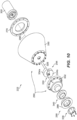
- FIGS. 10 and 11 illustrate a cutter head 222 according to another embodiment.
- the cutter head 22 is generally similar to the cutter head 22 described above with respect to FIGS. 4-6 , and similar features are identified by similar reference numbers, plus 200.
- the cutter head 222 includes a cutting bit 286, an inertial member 290, an exciter member 294, and a motor 302 for driving the exciter member 294.
- the inertial member includes a body 330 and a cap 332 coupled to an end of the body 330.
- the cutting bit 286 generally has a ring or annular shape and includes a cutting edge 288.
- the cutting bit 286 is coupled to an end of the cap 332 by a retaining ring 336 ( FIG. 10 ).
- a radial and thrust bearing plate 340 ( FIG. 10 ) is positioned between the cutting bit 286 and the end of the cap 332 to support the cutting bit 286 for rotation relative to the cap 332.
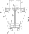
- the cutter head 22 is controlled by directly sensing an indicator of the force exerted by the cutting bit 86 on the mine wall 26 in real-time.
- the control system may include a load cell (e.g., a multi-axis strain gauge; not shown) positioned on the cutting bit 86 to detect the stress on the cutting bit. The cutting force is calculated based on the measured stress.
- the control system may include sensors, such as infrared sensors, for monitoring the temperature at the cutting interface. The load sensor and thermal sensor provide accurate measurements of the performance of the cutter head 22, permitting accurate adjustment of certain parameters (such as cutting speed or feed force) in order to optimize the closed loop control and optimize the power provided at the cutting interface.
- the control system includes measuring a cutting speed of the cutting bit 86 with non-contact sensors and varying a feed rate of the cutter head 22 to optimize a cutting rate. Other embodiments can incorporate other adaptive features to optimize performance of the cutter head 22.
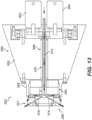
- the slave cutter(s) are de-tuned by altering one of the operating parameters, (e.g., the rotation speed of the cutting bit). For example, a master cutter head operates at nominal speed, while the slave cutter heads operate at speeds slower than the rated value. If a slave cutter head begins to lag, its speed is increased until its cutting performance matches the master cutter.
- the parameter(s) of the master cutter head are continuously varied to maximize its power output as described above with respect to the single cutter head system.
- the invention provides, among other things, a cutter head for a mining machine.
- a cutter head for a mining machine.
Landscapes
- Engineering & Computer Science (AREA)
- Mining & Mineral Resources (AREA)
- Life Sciences & Earth Sciences (AREA)
- General Life Sciences & Earth Sciences (AREA)
- Geochemistry & Mineralogy (AREA)
- Geology (AREA)
- Mechanical Engineering (AREA)
- Environmental & Geological Engineering (AREA)
- Drilling And Exploitation, And Mining Machines And Methods (AREA)
- Earth Drilling (AREA)
- Remote Sensing (AREA)
- Processing Of Stones Or Stones Resemblance Materials (AREA)
- Perforating, Stamping-Out Or Severing By Means Other Than Cutting (AREA)
- Sawing (AREA)
- Working Measures On Existing Buildindgs (AREA)
- Operation Control Of Excavators (AREA)
Applications Claiming Priority (4)
| Application Number | Priority Date | Filing Date | Title |
|---|---|---|---|
| US201261701256P | 2012-09-14 | 2012-09-14 | |
| EP17201428.4A EP3306034B1 (en) | 2012-09-14 | 2013-09-16 | Cutter head for mining machine |
| EP13837734.6A EP2895690B1 (en) | 2012-09-14 | 2013-09-16 | Cutter head for mining machine |
| PCT/US2013/060017 WO2014043658A2 (en) | 2012-09-14 | 2013-09-16 | Cutter head for mining machine |
Related Parent Applications (2)
| Application Number | Title | Priority Date | Filing Date |
|---|---|---|---|
| EP17201428.4A Division EP3306034B1 (en) | 2012-09-14 | 2013-09-16 | Cutter head for mining machine |
| EP13837734.6A Division EP2895690B1 (en) | 2012-09-14 | 2013-09-16 | Cutter head for mining machine |
Publications (2)
| Publication Number | Publication Date |
|---|---|
| EP3663513A1 EP3663513A1 (en) | 2020-06-10 |
| EP3663513B1 true EP3663513B1 (en) | 2024-07-03 |
Family
ID=50273716
Family Applications (6)
| Application Number | Title | Priority Date | Filing Date |
|---|---|---|---|
| EP19218675.7A Active EP3663513B1 (en) | 2012-09-14 | 2013-09-16 | Cutter head for mining machine |
| EP13837734.6A Active EP2895690B1 (en) | 2012-09-14 | 2013-09-16 | Cutter head for mining machine |
| EP19218632.8A Active EP3656976B1 (en) | 2012-09-14 | 2013-09-16 | Cutter head for mining machine |
| EP17201425.0A Active EP3301254B1 (en) | 2012-09-14 | 2013-09-16 | Cutter head for mining machine |
| EP19218676.5A Active EP3656977B1 (en) | 2012-09-14 | 2013-09-16 | Cutter head for mining machine |
| EP17201428.4A Active EP3306034B1 (en) | 2012-09-14 | 2013-09-16 | Cutter head for mining machine |
Family Applications After (5)
| Application Number | Title | Priority Date | Filing Date |
|---|---|---|---|
| EP13837734.6A Active EP2895690B1 (en) | 2012-09-14 | 2013-09-16 | Cutter head for mining machine |
| EP19218632.8A Active EP3656976B1 (en) | 2012-09-14 | 2013-09-16 | Cutter head for mining machine |
| EP17201425.0A Active EP3301254B1 (en) | 2012-09-14 | 2013-09-16 | Cutter head for mining machine |
| EP19218676.5A Active EP3656977B1 (en) | 2012-09-14 | 2013-09-16 | Cutter head for mining machine |
| EP17201428.4A Active EP3306034B1 (en) | 2012-09-14 | 2013-09-16 | Cutter head for mining machine |
Country Status (12)
| Country | Link |
|---|---|
| US (5) | US9470087B2 (pl) |
| EP (6) | EP3663513B1 (pl) |
| CN (2) | CN104718346B (pl) |
| AU (5) | AU2013315063B2 (pl) |
| BR (2) | BR112015005645B1 (pl) |
| CA (2) | CA3115588A1 (pl) |
| CL (3) | CL2015000627A1 (pl) |
| FI (3) | FI3663513T3 (pl) |
| PE (4) | PE20241767A1 (pl) |
| PL (6) | PL3656977T3 (pl) |
| WO (1) | WO2014043658A2 (pl) |
| ZA (1) | ZA201501723B (pl) |
Families Citing this family (21)
| Publication number | Priority date | Publication date | Assignee | Title |
|---|---|---|---|---|
| BR112015005645B1 (pt) * | 2012-09-14 | 2021-03-30 | Joy Global Underground Mining Llc | Cabeça de corte para máquina de mineração e máquina de mineração |
| CN104912568B (zh) * | 2015-06-17 | 2017-07-04 | 唐忠盛 | 高频振动横向铣挖头及具有该铣挖头的铣挖机和掘进机 |
| PL4191019T3 (pl) | 2016-01-27 | 2025-09-08 | Joy Global Underground Mining Llc | Maszyna górnicza z wieloma głowicami urabiającymi |
| AU2017271618B2 (en) | 2016-05-27 | 2023-01-05 | Joy Global Underground Mining Llc | Cutting device with wear elements |
| RU2752854C2 (ru) | 2016-08-19 | 2021-08-11 | ДЖОЙ ГЛОБАЛ АНДЕРГРАУНД МАЙНИНГ ЭлЭлСи | Режущее устройство и опора для него |
| US11391149B2 (en) | 2016-08-19 | 2022-07-19 | Joy Global Underground Mining Llc | Mining machine with articulating boom and independent material handling system |
| EP3500730B1 (en) | 2016-08-19 | 2023-10-18 | Joy Global Underground Mining LLC | Mining machine with articulating boom and independent material handling system |
| FI3516153T3 (fi) | 2016-09-23 | 2024-02-16 | Joy Global Underground Mining Llc | Kallionleikkuulaite |
| US11094208B2 (en) * | 2016-09-30 | 2021-08-17 | The Boeing Company | Stereo camera system for collision avoidance during aircraft surface operations |
| AU2016428997B2 (en) * | 2016-11-10 | 2023-04-13 | Sandvik Intellectual Property Ab | Roller cutter unit for undercutting machine |
| US10362265B2 (en) * | 2017-04-16 | 2019-07-23 | Facebook, Inc. | Systems and methods for presenting content |
| PL3495608T3 (pl) * | 2017-06-05 | 2021-07-05 | Joy Global Underground Mining Llc | Układ i sposób określania wydajności urządzenia przemysłowego |
| EP3814608B1 (en) | 2018-07-25 | 2024-11-27 | Joy Global Underground Mining LLC | Rock cutting assembly |
| CN109098709B (zh) * | 2018-10-29 | 2024-02-13 | 三一重型装备有限公司 | 伸缩式掘进机截割头系统及掘进机 |
| CN109519186A (zh) * | 2018-12-10 | 2019-03-26 | 中交公局桥隧工程有限公司 | 一种悬臂式掘进机 |
| CN109902448B (zh) * | 2019-04-24 | 2022-05-17 | 西北工业大学 | 考虑刀具磨损的机床加工过程能耗模型建模方法 |
| CN211115995U (zh) * | 2019-12-27 | 2020-07-28 | 李恒 | 一种煤矿综掘机减震装置 |
| CN112196575B (zh) * | 2020-12-02 | 2021-03-02 | 中国铁建重工集团股份有限公司 | 一种水平钻机自动控制方法 |
| CN112983452B (zh) * | 2021-03-04 | 2022-08-23 | 中国矿业大学 | 一种巷道综合掘进成套装备掘进工艺及协同定位控制方法 |
| CA3229446A1 (en) * | 2021-08-18 | 2023-02-23 | Barend Jacobus Jordaan | Reef cutting machine |
| CN119145856B (zh) * | 2024-11-18 | 2025-01-21 | 中国安全生产科学研究院 | 一种带有智能数字孪生系统的固体钾盐矿机械开采设备 |
Citations (1)
| Publication number | Priority date | Publication date | Assignee | Title |
|---|---|---|---|---|
| US1510628A (en) * | 1924-10-07 | morgan |
Family Cites Families (187)
| Publication number | Priority date | Publication date | Assignee | Title |
|---|---|---|---|---|
| DE1440261U (pl) | ||||
| US1304352A (en) * | 1919-05-20 | Appabatus foe mining | ||
| US1093787A (en) * | 1909-10-30 | 1914-04-21 | Harry A Kuhn | Method of tunneling. |
| US1953326A (en) * | 1913-06-23 | 1934-04-03 | Olive Eugenie Morgan | Method of mining coal |
| US1735583A (en) * | 1913-07-05 | 1929-11-12 | Morgan Olive Eugene | Apparatus for mining coal |
| US1340731A (en) * | 1913-08-04 | 1920-05-18 | Edmund C Morgan | Mining and loading machine |
| US2336337A (en) | 1942-08-13 | 1943-12-07 | John A Zublin | Heavy duty gyrating bit |
| US2336335A (en) | 1942-08-13 | 1943-12-07 | John A Zublin | Rotary hammering bit |
| US2466709A (en) * | 1944-10-02 | 1949-04-12 | Richard D Karr | Tunneling machine |
| US2511267A (en) | 1945-10-09 | 1950-06-13 | Budd Co | Bulkhead door structure |
| US2745651A (en) | 1947-07-08 | 1956-05-15 | Gewerk Eisenhuette Westfalia | Mining planer |
| US2517267A (en) | 1949-03-07 | 1950-08-01 | George C Watson | Attachment for the cutter bars of mining machines |
| US2756039A (en) | 1949-04-08 | 1956-07-24 | Joy Mfg Co | Guides for flexible elements of coal mining apparatus |
| US2654586A (en) | 1950-02-04 | 1953-10-06 | Goodman Mfg Co | Digging machine for mining coal |
| US2659565A (en) | 1950-10-05 | 1953-11-17 | Weatherhead Co | Cylinder valve |
| US2619338A (en) | 1950-11-03 | 1952-11-25 | Goodman Mfg Co | Coal mining machine |
| US2619339A (en) | 1950-12-11 | 1952-11-25 | Goodman Mfg Co | Mining machine |
| US2659585A (en) * | 1951-06-29 | 1953-11-17 | Goodman Mfg Co | Power drive connection for combined rotatable and oscillatable mining tools |
| US2776823A (en) | 1954-05-17 | 1957-01-08 | Joy Mfg Co | Rotating cutter and core breaker for continuous miner |
| US3115588A (en) | 1958-02-05 | 1963-12-24 | Raytheon Co | Electroacoustical apparatus |
| DE1440261B1 (de) | 1959-07-22 | 1970-04-16 | Separator Ab | Schweisszange mit auswechselbarer Andrueckvorrichtung |
| US3197256A (en) | 1961-01-23 | 1965-07-27 | Goodman Mfg Co | Continuous mining machine with loading means |
| US3157437A (en) | 1962-09-19 | 1964-11-17 | Goodman Mfg Co | Continuous mining machine of the oscillating head type |
| GB1039981A (en) | 1963-10-02 | 1966-08-24 | Greenside Machine Co Ltd | Improvements in or relating to heading and ripping machines for mining |
| US3353871A (en) | 1964-08-05 | 1967-11-21 | Lee Norse Co | Continuous mining machine with oscillating rotary cutter heads |
| US3408109A (en) | 1965-07-09 | 1968-10-29 | Mining Progress Inc | Mining machine with rocker arm controlled front pusher plate |
| DE1257713B (de) | 1965-07-26 | 1968-01-04 | Bergwerksverband Gmbh | Antrieb fuer drehend arbeitende Bohrmaschinen zum Vortrieb von soehligen bis seigeren Grubenbauen |
| US3302974A (en) | 1966-02-18 | 1967-02-07 | Westinghouse Air Brake Co | Ripper type mining machine having oppositely moving oscillating ripper heads |
| US3374033A (en) * | 1966-02-21 | 1968-03-19 | Lee Norse Co | Cutter head having fluid supply means |
| DE1534648C3 (de) | 1966-03-19 | 1975-08-21 | Atlas Copco Mct Ab, Nacka (Schweden) | Vortriebsmaschine für Tunnels, Stollen, Kanäle od.dgl |
| US3355215A (en) * | 1966-11-07 | 1967-11-28 | Smith Ind International Inc | Oscillating tunneling machine |
| GB1311094A (en) | 1969-03-25 | 1973-03-21 | Dubois M | Machine and process for digging undergrojnd galleries |
| SU619117A3 (ru) | 1969-08-06 | 1978-08-05 | Коул Индастри (Патентс) Лимитед (Фирма) | Исполнительный орган барабанного типа дл горной машины |
| US3554604A (en) * | 1969-11-24 | 1971-01-12 | Robbins & Assoc James S | Vibrator systems and rock cutter type utilization mechanisms |
| US3647263A (en) | 1970-03-19 | 1972-03-07 | Atlas Copco Ab | Tunnelling machines and the like |
| DE2018778A1 (pl) | 1970-04-18 | 1971-12-30 | ||
| SE358606B (pl) | 1970-06-22 | 1973-08-06 | Rottneros Ab | |
| AU466244B2 (en) | 1970-08-18 | 1975-10-07 | James S. Robbins And Associates, Inc | Vibrator systems and rock cutter type utilization mechanisms |
| US3719404A (en) | 1970-11-17 | 1973-03-06 | Kidde & Co Walter | Crane boom having universally swiveled wear pads |
| DE2159351C3 (de) * | 1971-11-30 | 1981-02-26 | Salzgitter Maschinen Und Anlagen Ag, 3320 Salzgitter | Bohrgerät mit wenigstens einer mit einem Unwuchtvibrator versehenen Schneidrolle |
| SU750061A1 (ru) | 1971-12-21 | 1980-07-23 | За витель А. Н. Супрунов | Исполнительный орган горного комбайна |
| SU514097A1 (ru) | 1973-04-10 | 1976-05-15 | Шахта "Нагорная" Комбината "Южкузбассуголь" | Проходческий комбайн |
| FR2229855B1 (pl) | 1973-05-16 | 1977-10-07 | Eickhoff Geb | |
| US3840271A (en) | 1973-06-27 | 1974-10-08 | Robbins Co | Tunneling machine having swinging arms carrying cutter discs |
| LU68283A1 (pl) | 1973-08-22 | 1975-05-21 | ||
| LU68289A1 (pl) | 1973-08-22 | 1975-05-21 | ||
| US3922017A (en) * | 1973-08-23 | 1975-11-25 | Caterpillar Tractor Co | Impact material fracturing device for excavators and the like |
| US3972571A (en) | 1973-09-14 | 1976-08-03 | The Warner & Swasey Company | Boom slider assembly |
| US4096917A (en) | 1975-09-29 | 1978-06-27 | Harris Jesse W | Earth drilling knobby bit |
| JPS5540058Y2 (pl) | 1976-03-31 | 1980-09-18 | ||
| AT342537B (de) | 1976-05-13 | 1978-04-10 | Voest Ag | Schrammaschine |
| SU581263A1 (ru) | 1976-07-08 | 1977-11-25 | Научно-Исследовательский Горнорудный Институт | Исполнительный орган проходческого комбайна |
| US4087131A (en) * | 1976-11-01 | 1978-05-02 | Rapidex, Inc. | Drag bit excavation |
| DE2809132A1 (de) | 1978-03-03 | 1979-09-06 | Gewerk Eisenhuette Westfalia | Bergbau-gewinnungsmaschine |
| DE2832319C2 (de) * | 1978-07-22 | 1984-09-27 | M.A.N. Maschinenfabrik Augsburg-Nuernberg Ag, 4200 Oberhausen | Hydromechanischer Hobel mit Schneid- und Brechköpfen |
| DE2836131C2 (de) | 1978-08-18 | 1986-11-27 | Gewerkschaft Eisenhütte Westfalia GmbH, 4670 Lünen | Schildvortriebseinrichtung |
| JPS5540058U (pl) | 1978-09-07 | 1980-03-14 | ||
| JPS5540058A (en) | 1978-09-12 | 1980-03-21 | Shin Meiwa Ind Co Ltd | Profiling device of welding machine |
| US4230372A (en) | 1978-12-04 | 1980-10-28 | H. B. Zachry Company | Dual rock cutter wheel trencher |
| SU804832A1 (ru) | 1978-12-06 | 1981-02-15 | Криворожский Ордена Трудового Красногознамени Горнорудный Институт | Исполнительный орган проходческогоКОМбАйНА |
| GB2037844B (en) | 1978-12-15 | 1982-10-13 | Coal Industry Patents Ltd | Cutter unit assemblies for excavating machines and to excavating machines including cutter unit assemblies |
| US4662684A (en) | 1979-12-13 | 1987-05-05 | H. B. Zachery Corporation | Rotary rock and trench cutting saw |
| US4377311A (en) | 1981-02-04 | 1983-03-22 | Fox Manufacturing Company Pty. Limited | Multi-purpose mining machine |
| SU962626A1 (ru) | 1981-03-27 | 1982-09-30 | Тульский Ордена Трудового Красного Знамени Политехнический Институт | Исполнительный орган проходческого комбайна |
| US4372403A (en) | 1981-09-14 | 1983-02-08 | Beeman Archie W | Eccentric rotary bit |
| US4516807A (en) * | 1981-10-13 | 1985-05-14 | Coal Industry (Patents) Limited | Fluid supply systems for rotary cutter heads for mining machines and rotary cutter heads comprising fluid supply systems |
| DE3235009A1 (de) | 1982-01-29 | 1983-08-25 | Friedrich Wilhelm Paurat | Verfahren zum betrieb einer teilschnittmaschine und fuer das verfahren eingerichtete teilschnittmaschine |
| DE3327941A1 (de) | 1983-08-03 | 1985-02-21 | Gewerkschaft Eisenhütte Westfalia, 4670 Lünen | Abbau- und vortriebsmaschine |
| US4548442A (en) | 1983-12-06 | 1985-10-22 | The Robbins Company | Mobile mining machine and method |
| GB2152974B (en) * | 1984-01-20 | 1987-05-07 | Coal Ind | Animal feeding bowls |
| JPS60181487A (ja) * | 1984-02-24 | 1985-09-17 | 財団法人石炭技術研究所 | 負荷制御装置を有するダブルレンジング・ドラムカツタ |
| US4682819A (en) * | 1984-03-12 | 1987-07-28 | Roger Masse | Method and apparatus for drilling hard material |
| DE3414195A1 (de) | 1984-04-14 | 1985-10-24 | Charbonnages De France, Paris | Drehkoerper eines schneidkopfes einer teilschnittvortriebsmaschine |
| GB8421670D0 (en) * | 1984-08-25 | 1984-09-26 | Minnovation Ltd | Mining machine |
| US4664036A (en) | 1984-08-27 | 1987-05-12 | Si Handling Systems, Inc. | Conveyor having curved track section |
| GB8513772D0 (en) * | 1985-05-31 | 1985-07-03 | Coal Industry Patents Ltd | Resultant velocity control |
| SU1323552A1 (ru) | 1985-11-22 | 1987-07-15 | Восточный научно-исследовательский и проектный институт огнеупорной промышленности | Способ изготовлени углеродсодержащего огнеупора |
| GB8528917D0 (en) * | 1985-11-23 | 1986-01-02 | Minnovation Ltd | Mining machine |
| SU1328521A1 (ru) | 1986-03-31 | 1987-08-07 | Подмосковный Научно-Исследовательский И Проектно-Конструкторский Угольный Институт | Устройство дл подземной добычи полезного ископаемого |
| CH672908A5 (pl) | 1986-04-15 | 1990-01-15 | Bechem Hannelore | |
| AT386457B (de) | 1986-11-26 | 1988-08-25 | Voest Alpine Ag | Schraemmaschine |
| US4848486A (en) | 1987-06-19 | 1989-07-18 | Bodine Albert G | Method and apparatus for transversely boring the earthen formation surrounding a well to increase the yield thereof |
| DE3801219A1 (de) | 1987-07-08 | 1989-01-19 | Dosco Overseas Eng Ltd | Ausbruchverfahren- und vorrichtung |
| AU603431B2 (en) | 1987-10-28 | 1990-11-15 | Dosco Overseas Engineering Ltd | Apparatus for excavating a recess |
| US4750513A (en) | 1987-11-19 | 1988-06-14 | Chrysler Motors Corporation | Pivotally mounted fuel collector |
| GB2212836B (en) | 1987-11-25 | 1991-12-04 | Anderson Strathclyde Plc | Mining machine |
| CH677890A5 (de) | 1987-12-30 | 1991-07-15 | Hannelore Bechem | Exzenterantrieb fuer bohrwerkzeuge. |
| GB2214963B (en) | 1988-02-13 | 1992-05-06 | Gullick Dobson Ltd | Mine roof supports |
| GB2216158A (en) * | 1988-02-26 | 1989-10-04 | Sasol Mining | High pressure water assisted mining and tunnelling machine |
| JP2634655B2 (ja) | 1988-11-30 | 1997-07-30 | 日本鉱機株式会社 | 軟岩用トンネル掘進機 |
| US5028092A (en) * | 1989-04-05 | 1991-07-02 | Coski Enterprises, Ltd. | Impact kerfing rock cutter and method |
| AT392119B (de) | 1989-05-17 | 1991-01-25 | Voest Alpine Maschinenbau | Schraemmaschine |
| JPH0733114Y2 (ja) | 1989-05-17 | 1995-07-31 | 大同特殊鋼株式会社 | ローラハース式加熱炉における昇降ローラ用開口部のシール機構 |
| US4946227A (en) * | 1989-05-22 | 1990-08-07 | Esso Resources Canada Limited | Bucket wheel assembly |
| SU1712599A1 (ru) | 1989-06-05 | 1992-02-15 | Научно-Исследовательский Горнорудный Институт | Горный комбайн |
| US4968098A (en) * | 1989-09-11 | 1990-11-06 | Atlantic Richfield Company | Coal seam discontinuity sensor and method for coal mining apparatus |
| SU1744249A1 (ru) | 1989-12-05 | 1992-06-30 | Всесоюзный научно-исследовательский и проектно-конструкторский институт добычи угля гидравлическим способом | Опорно-подающее устройство горной машины |
| SU1731946A1 (ru) * | 1990-02-22 | 1992-05-07 | Новомосковский филиал Московского химико-технологического института им.Д.И.Менделеева | Устройство управлени многоприводным механизмом подачи горной машины |
| CH684786A5 (de) * | 1990-04-09 | 1994-12-30 | Bechem Hannelore | Exzenteraktivierte radial schwingende rotierende Werkzeughalter. |
| US5205612A (en) * | 1990-05-17 | 1993-04-27 | Z C Mines Pty. Ltd. | Transport apparatus and method of forming same |
| US5087102A (en) | 1990-07-18 | 1992-02-11 | Kiefer Heinz E | Continuous mining machine |
| US5112111A (en) | 1990-12-10 | 1992-05-12 | Addington Resources, Inc. | Apparatus and method for continuous mining |
| DE4103544C1 (en) | 1991-02-06 | 1992-04-09 | Paurat Gmbh, 4223 Voerde, De | Deep mining heading-winning machine - has tracked propulsion system and slewing and ranging boom |
| US5210997A (en) | 1991-05-17 | 1993-05-18 | Mountcastle Jr Deliston L | Articulated boom tractor mounted cutter assembly |
| DE4123307C1 (pl) | 1991-07-13 | 1992-12-24 | O & K Orenstein & Koppel Ag, 1000 Berlin, De | |
| US5234257A (en) | 1991-10-11 | 1993-08-10 | The Robbins Company | Mobile mining machine having tilted swing axis and method |
| DE4440261C2 (de) | 1994-11-11 | 1997-04-30 | Wirth Co Kg Masch Bohr | Maschine zum Vortreiben von Strecken, Tunneln od. dgl. |
| CA2138461A1 (en) | 1994-12-19 | 1996-06-20 | Jacques Andre Saint-Pierre | Automatic control of a machine used for excavating drifts, tunnels, stopes, caverns or the like |
| CA2141984C (en) | 1995-02-07 | 2002-11-26 | Herbert A. Smith | Continuous control system for a mining or tunnelling machine |
| US5601153A (en) | 1995-05-23 | 1997-02-11 | Smith International, Inc. | Rock bit nozzle diffuser |
| US5676125A (en) | 1995-06-23 | 1997-10-14 | Kelly; Patrick | Excavator mounted concrete saw |
| DE19547698C2 (de) * | 1995-12-20 | 2000-08-17 | Wirtgen Gmbh | Vorrichtung und Verfahren zum Abfräsen von harten Oberflächen, insbesondere von Straßenbelägen |
| US5697733A (en) | 1996-01-11 | 1997-12-16 | Marsh, Jr.; Richard O. | Centrifugal force vibration apparatus and system |
| US6364418B1 (en) * | 1996-11-12 | 2002-04-02 | Amvest Systems, Inc. | Cutting heads for horizontal remote mining system |
| JP3168538B2 (ja) | 1997-04-19 | 2001-05-21 | チャン リー ウー | 滑りベアリング及びその製造方法 |
| US6010210A (en) * | 1997-06-04 | 2000-01-04 | Hewlett-Packard Company | Ink container having a multiple function chassis |
| RU2142561C1 (ru) | 1998-02-02 | 1999-12-10 | Атрушкевич Аркадий Анисимович | Проходческо-очистной комбайн |
| DE19900906A1 (de) | 1999-01-13 | 2000-07-20 | Bechem Hannelore | Rollenmeißel zum Schlitzen und Abtragen von Gestein, Mineralien etc. |
| AUPP822499A0 (en) | 1999-01-20 | 1999-02-11 | Terratec Asia Pacific Pty Ltd | Oscillating & nutating disc cutter |
| AUPP846599A0 (en) * | 1999-02-04 | 1999-02-25 | Sugden, David Burnet | Cutting device |
| WO2002001045A1 (de) | 2000-06-28 | 2002-01-03 | Voest-Alpine Bergtechnik Gesellschaft M.B.H. | Vortriebs- oder gewinnungsmaschine für den abbau von gestein |
| RU2187640C1 (ru) | 2001-01-29 | 2002-08-20 | Читинский государственный технический университет | Исполнительный орган горного комбайна |
| SE522997C2 (sv) | 2001-02-23 | 2004-03-23 | Sandvik Ab | Verktygshuvud och verktyg |
| RU2209979C2 (ru) | 2001-07-23 | 2003-08-10 | Егошин Воля Васильевич | Проходческий агрегат |
| FI118306B (fi) | 2001-12-07 | 2007-09-28 | Sandvik Tamrock Oy | Menetelmä ja laitteisto kallionporauslaitteen toiminnan ohjaamiseksi |
| US6857706B2 (en) | 2001-12-10 | 2005-02-22 | Placer Dome Technical Services Limited | Mining method for steeply dipping ore bodies |
| AT413047B (de) | 2002-01-23 | 2005-10-15 | Voest Alpine Bergtechnik | Träger für eine fliegende schneiddiskenlagerung |
| AUPS186802A0 (en) | 2002-04-22 | 2002-05-30 | Odyssey Technology Pty Ltd | Oscillating disc cutter with speed controlling bearings |
| AUPS186902A0 (en) * | 2002-04-22 | 2002-05-30 | Odyssey Technology Pty Ltd | Rock cutting machine |
| US7695071B2 (en) | 2002-10-15 | 2010-04-13 | Minister Of Natural Resources | Automated excavation machine |
| US7930019B2 (en) | 2002-12-02 | 2011-04-19 | Cardiac Pacemakers, Inc. | Method and apparatus for phonocardiographic image acquisition and presentation |
| DE10339595A1 (de) | 2003-08-26 | 2005-04-07 | Siemens Ag | Verfahren zur Vorhersage und Steuerung der Vergießbarkeit von Flüssigstahl |
| RU2276728C1 (ru) | 2004-12-16 | 2006-05-20 | Санкт-Петербургский государственный горный институт им. Г.В. Плеханова (Технический университет) | Способ удержания проходческой машины в заданном положении |
| WO2006075910A1 (en) | 2005-01-14 | 2006-07-20 | Superior Highwall Miners, Inc. | Anchoring device and method for fixation of a launching unit for highwall mining |
| US8079647B2 (en) * | 2005-03-23 | 2011-12-20 | Longyear Tm, Inc. | Vibratory milling machine having linear reciprocating motion |
| US7490911B2 (en) * | 2005-06-18 | 2009-02-17 | Dbt Gmbh | Drive device for rotating and oscillating a tool, and a compatible tool for mining |
| JP2007011963A (ja) * | 2005-07-04 | 2007-01-18 | Fuji Xerox Co Ltd | 端末装置による情報処理方法およびシステム |
| DE102006032680B4 (de) | 2006-07-13 | 2008-07-24 | Dbt Gmbh | Walzenladeantriebsbaugruppe und Führungsschuh hierfür |
| CA2671822C (en) * | 2006-12-07 | 2013-08-27 | Nabors Global Holdings, Ltd. | Automated mse-based drilling apparatus and methods |
| DE202007001277U1 (de) | 2007-01-23 | 2008-03-13 | Dbt Gmbh | Führungsschuh für einen Walzenlader und Verschleißeinsätze für Führungsschuhe |
| RU2337756C1 (ru) | 2007-01-31 | 2008-11-10 | Константин Евсеевич Белоцерковский | Способ управления технологическими параметрами конусной дробилки |
| US7934776B2 (en) * | 2007-08-31 | 2011-05-03 | Joy Mm Delaware, Inc. | Mining machine with driven disc cutters |
| US7703857B2 (en) | 2007-09-08 | 2010-04-27 | Joy Mm Delaware, Inc. | Continuous miner having a sumping frame |
| US7559857B2 (en) | 2007-10-31 | 2009-07-14 | Bridgestone Sports Co., Ltd. | Golf ball |
| AT10343U1 (de) | 2007-11-15 | 2009-01-15 | Sandvik Mining & Constr Oy | Vortriebsmaschine |
| AT506501B1 (de) | 2008-02-15 | 2011-04-15 | Sandvik Mining & Constr Oy | Strecken-vortriebsmaschine |
| AU2009251268A1 (en) | 2008-05-26 | 2009-12-03 | 9Dot Solutions (Pty) Ltd | Mining machine and method of mining |
| MX2010002257A (es) * | 2008-07-28 | 2010-05-03 | Eickhoff Bergbautechnik Gmbh | Metodo para controlar una maquina de extraccion por corte. |
| MX2010000225A (es) * | 2008-08-09 | 2010-07-20 | Eickhoff Bergbautechnik Gmbh | Metodo y dispositivo para la supervision de una maquina para extraccion de cortes. |
| US8128323B2 (en) | 2009-04-14 | 2012-03-06 | Planet Products Corporation | Driven tool assembly |
| DE102009030130B9 (de) * | 2009-06-24 | 2011-06-09 | Rag Aktiengesellschaft | Verfahren zur automatisierten Herstellung einer definierten Streböffnung durch neigungsgestützte Radarnavigation der Walze bei einem Walzenschrämlader und eine Vorrichtung hierfür |
| CL2009001978A1 (es) | 2009-10-20 | 2010-02-19 | Corporacion Nac Del Cobre De Chile | Sistema liberador y reductor de tamano del material contenido en puntos de extraccion en faenas mineras con explotacion por bloques, comprende un mecanismo rotor, un brazo extensible y un martillo picador, el mecanismo rotor se dispone para desplazarse sobre un par de vigas de soporte dispuestas en el piso o en el techo. |
| US8157331B2 (en) * | 2009-11-16 | 2012-04-17 | Joy Mm Delaware, Inc. | Method for steering a mining machine cutter |
| US8636324B2 (en) | 2010-01-22 | 2014-01-28 | Joy Mm Delaware, Inc. | Mining machine with driven disc cutters |
| WO2012115545A1 (en) | 2011-02-22 | 2012-08-30 | Telefonaktiebolaget L M Ericsson (Publ) | Method and device for congestion situations |
| GB2505107A (en) | 2011-05-16 | 2014-02-19 | Caterpillar Global Mining Gmbh | Mobile Mining machine and method for driving tunnels, roadways or shafts, in particular in hard rock |
| CN103206213A (zh) | 2011-09-11 | 2013-07-17 | 刘素华 | 一种保持冲击机构垂直冲击的方法及实施该方法的垂直升降冲削采掘机 |
| CN102305067A (zh) | 2011-09-23 | 2012-01-04 | 李欣 | 一种掘进机机构 |
| SE537425C2 (sv) | 2011-09-27 | 2015-04-28 | Atlas Copco Rock Drills Ab | Anordning och förfarande för drivning av tunnlar, orter eller liknande |
| CN102513998A (zh) | 2011-12-28 | 2012-06-27 | 广西大学 | 一种空间五活动度钻孔机器人机构 |
| CN102587911B (zh) * | 2012-03-08 | 2014-04-23 | 三一重型装备有限公司 | 掘进机的掘进控制系统和控制方法、掘进机 |
| CN202500560U (zh) | 2012-03-23 | 2012-10-24 | 中国矿业大学 | 旋挖式采煤机与掘进机截割部 |
| CN102606154B (zh) | 2012-04-06 | 2014-01-15 | 中铁隧道装备制造有限公司 | 双圆刀盘煤巷掘进机 |
| CN103498671B (zh) | 2012-05-12 | 2018-09-28 | 刘素华 | 摇臂设有过煤空间采掘机 |
| CN102704927B (zh) | 2012-06-15 | 2014-12-24 | 马晓山 | 一种综合机械化岩巷掘进机组 |
| CN102733803A (zh) | 2012-06-21 | 2012-10-17 | 中铁隧道装备制造有限公司 | 复合式悬臂掘进机 |
| BR112015005645B1 (pt) | 2012-09-14 | 2021-03-30 | Joy Global Underground Mining Llc | Cabeça de corte para máquina de mineração e máquina de mineração |
| US9074425B2 (en) | 2012-12-21 | 2015-07-07 | Weatherford Technology Holdings, Llc | Riser auxiliary line jumper system for rotating control device |
| CN202991028U (zh) | 2012-12-28 | 2013-06-12 | 方瑜 | 掘进机 |
| GB2514884A (en) | 2013-03-15 | 2014-12-10 | Joy Mm Delaware Inc | Cutter head for longwall shearer |
| EP2821591B1 (en) | 2013-07-04 | 2015-09-16 | Sandvik Intellectual Property AB | Mining machine roof bolting rig |
| EP2924236B1 (en) | 2014-03-28 | 2016-07-13 | Sandvik Intellectual Property AB | Mining drill rig |
| DE102014218028B4 (de) | 2014-09-09 | 2016-05-04 | Infineon Technologies Ag | Slave-Vorrichtung für ein serielles, synchrones Vollduplexbussystem |
| WO2016055087A1 (en) | 2014-10-06 | 2016-04-14 | Sandvik Intellectual Property Ab | Cutting apparatus |
| CN104500086B (zh) | 2015-01-15 | 2017-01-18 | 山西大同大学 | 巷道无人掘锚一体机 |
| PL4191019T3 (pl) | 2016-01-27 | 2025-09-08 | Joy Global Underground Mining Llc | Maszyna górnicza z wieloma głowicami urabiającymi |
| AU2017271618B2 (en) | 2016-05-27 | 2023-01-05 | Joy Global Underground Mining Llc | Cutting device with wear elements |
| EP3500730B1 (en) | 2016-08-19 | 2023-10-18 | Joy Global Underground Mining LLC | Mining machine with articulating boom and independent material handling system |
| RU2752854C2 (ru) | 2016-08-19 | 2021-08-11 | ДЖОЙ ГЛОБАЛ АНДЕРГРАУНД МАЙНИНГ ЭлЭлСи | Режущее устройство и опора для него |
| US11391149B2 (en) | 2016-08-19 | 2022-07-19 | Joy Global Underground Mining Llc | Mining machine with articulating boom and independent material handling system |
| FI3516153T3 (fi) | 2016-09-23 | 2024-02-16 | Joy Global Underground Mining Llc | Kallionleikkuulaite |
| CN108395482B (zh) | 2017-02-08 | 2021-02-05 | 西比曼生物科技(香港)有限公司 | 一种靶向cd20抗原嵌合抗原受体的构建及其工程化t细胞的活性鉴定 |
| CN110573219B (zh) | 2017-03-09 | 2021-10-29 | B·C·罗宾逊 | 水下推进装置 |
| CN110661897A (zh) | 2018-06-29 | 2020-01-07 | 华为技术有限公司 | 管理地址的方法和装置 |
| ES3049399T3 (en) | 2018-08-27 | 2025-12-16 | Intervet Int Bv | Combination vaccine |
| JP7286076B2 (ja) | 2018-08-27 | 2023-06-05 | ベイ マニュファクチャリング テクノロジーズ エルエルシー | ねじ転造用の位置決めおよびクランプシステム |
| JP2025040058A (ja) | 2023-09-11 | 2025-03-24 | 学校法人君が淵学園 | バッタ目昆虫用飼料添加剤、及びバッタ目昆虫の成長促進又は生残率向上方法 |
-
2013
- 2013-09-16 BR BR112015005645-8A patent/BR112015005645B1/pt active IP Right Grant
- 2013-09-16 PE PE2024001489A patent/PE20241767A1/es unknown
- 2013-09-16 CN CN201380053676.0A patent/CN104718346B/zh active Active
- 2013-09-16 WO PCT/US2013/060017 patent/WO2014043658A2/en not_active Ceased
- 2013-09-16 AU AU2013315063A patent/AU2013315063B2/en active Active
- 2013-09-16 CN CN201910052648.6A patent/CN110056351B/zh active Active
- 2013-09-16 EP EP19218675.7A patent/EP3663513B1/en active Active
- 2013-09-16 EP EP13837734.6A patent/EP2895690B1/en active Active
- 2013-09-16 FI FIEP19218675.7T patent/FI3663513T3/fi active
- 2013-09-16 PE PE2015000367A patent/PE20151270A1/es active IP Right Grant
- 2013-09-16 FI FIEP19218676.5T patent/FI3656977T3/fi active
- 2013-09-16 PL PL19218676.5T patent/PL3656977T3/pl unknown
- 2013-09-16 CA CA3115588A patent/CA3115588A1/en active Pending
- 2013-09-16 CA CA2884641A patent/CA2884641C/en active Active
- 2013-09-16 PL PL19218632.8T patent/PL3656976T3/pl unknown
- 2013-09-16 FI FIEP19218632.8T patent/FI3656976T3/fi active
- 2013-09-16 US US14/028,511 patent/US9470087B2/en active Active
- 2013-09-16 PE PE2024001490A patent/PE20241658A1/es unknown
- 2013-09-16 PL PL17201425T patent/PL3301254T3/pl unknown
- 2013-09-16 PL PL17201428T patent/PL3306034T3/pl unknown
- 2013-09-16 EP EP19218632.8A patent/EP3656976B1/en active Active
- 2013-09-16 PL PL19218675.7T patent/PL3663513T3/pl unknown
- 2013-09-16 PE PE2019002001A patent/PE20191678A1/es unknown
- 2013-09-16 PL PL13837734T patent/PL2895690T3/pl unknown
- 2013-09-16 BR BR122020010678-6A patent/BR122020010678B1/pt active IP Right Grant
- 2013-09-16 EP EP17201425.0A patent/EP3301254B1/en active Active
- 2013-09-16 EP EP19218676.5A patent/EP3656977B1/en active Active
- 2013-09-16 EP EP17201428.4A patent/EP3306034B1/en active Active
-
2015
- 2015-03-13 CL CL2015000627A patent/CL2015000627A1/es unknown
- 2015-03-13 ZA ZA2015/01723A patent/ZA201501723B/en unknown
-
2016
- 2016-09-15 US US15/266,386 patent/US10472961B2/en active Active
-
2018
- 2018-05-31 AU AU2018203820A patent/AU2018203820B2/en active Active
-
2019
- 2019-04-30 CL CL2019001190A patent/CL2019001190A1/es unknown
- 2019-11-08 US US16/678,656 patent/US11371346B2/en active Active
-
2020
- 2020-09-16 CL CL2020002400A patent/CL2020002400A1/es unknown
- 2020-11-27 AU AU2020277282A patent/AU2020277282B2/en active Active
-
2022
- 2022-05-16 US US17/745,561 patent/US11725512B2/en active Active
-
2023
- 2023-01-18 AU AU2023200238A patent/AU2023200238B2/en active Active
- 2023-07-10 US US18/349,574 patent/US12385395B2/en active Active
-
2025
- 2025-08-07 AU AU2025213620A patent/AU2025213620A1/en active Pending
Patent Citations (1)
| Publication number | Priority date | Publication date | Assignee | Title |
|---|---|---|---|---|
| US1510628A (en) * | 1924-10-07 | morgan |
Also Published As
Similar Documents
| Publication | Publication Date | Title |
|---|---|---|
| US12385395B2 (en) | Cutter head for mining machine | |
| CN101575973B (zh) | 具有驱动圆盘刀具的采矿机 | |
| RU2754529C2 (ru) | Устройство для резания горной породы | |
| EP3463777B1 (en) | Cutting device with wear elements | |
| CN110439585B (zh) | 自动操作连续采掘机的方法和系统 | |
| JP5705896B2 (ja) | 溝切機及び対地溝切方法 | |
| US3297101A (en) | Apparatus for boring a hole in rock |
Legal Events
| Date | Code | Title | Description |
|---|---|---|---|
| PUAI | Public reference made under article 153(3) epc to a published international application that has entered the european phase |
Free format text: ORIGINAL CODE: 0009012 |
|
| STAA | Information on the status of an ep patent application or granted ep patent |
Free format text: STATUS: THE APPLICATION HAS BEEN PUBLISHED |
|
| AC | Divisional application: reference to earlier application |
Ref document number: 3306034 Country of ref document: EP Kind code of ref document: P Ref document number: 2895690 Country of ref document: EP Kind code of ref document: P |
|
| AK | Designated contracting states |
Kind code of ref document: A1 Designated state(s): AL AT BE BG CH CY CZ DE DK EE ES FI FR GB GR HR HU IE IS IT LI LT LU LV MC MK MT NL NO PL PT RO RS SE SI SK SM TR |
|
| STAA | Information on the status of an ep patent application or granted ep patent |
Free format text: STATUS: REQUEST FOR EXAMINATION WAS MADE |
|
| 17P | Request for examination filed |
Effective date: 20201210 |
|
| RBV | Designated contracting states (corrected) |
Designated state(s): AL AT BE BG CH CY CZ DE DK EE ES FI FR GB GR HR HU IE IS IT LI LT LU LV MC MK MT NL NO PL PT RO RS SE SI SK SM TR |
|
| STAA | Information on the status of an ep patent application or granted ep patent |
Free format text: STATUS: EXAMINATION IS IN PROGRESS |
|
| 17Q | First examination report despatched |
Effective date: 20230120 |
|
| GRAP | Despatch of communication of intention to grant a patent |
Free format text: ORIGINAL CODE: EPIDOSNIGR1 |
|
| STAA | Information on the status of an ep patent application or granted ep patent |
Free format text: STATUS: GRANT OF PATENT IS INTENDED |
|
| INTG | Intention to grant announced |
Effective date: 20230921 |
|
| GRAJ | Information related to disapproval of communication of intention to grant by the applicant or resumption of examination proceedings by the epo deleted |
Free format text: ORIGINAL CODE: EPIDOSDIGR1 |
|
| STAA | Information on the status of an ep patent application or granted ep patent |
Free format text: STATUS: EXAMINATION IS IN PROGRESS |
|
| GRAP | Despatch of communication of intention to grant a patent |
Free format text: ORIGINAL CODE: EPIDOSNIGR1 |
|
| STAA | Information on the status of an ep patent application or granted ep patent |
Free format text: STATUS: GRANT OF PATENT IS INTENDED |
|
| INTC | Intention to grant announced (deleted) | ||
| INTG | Intention to grant announced |
Effective date: 20240130 |
|
| P01 | Opt-out of the competence of the unified patent court (upc) registered |
Effective date: 20240415 |
|
| GRAS | Grant fee paid |
Free format text: ORIGINAL CODE: EPIDOSNIGR3 |
|
| GRAA | (expected) grant |
Free format text: ORIGINAL CODE: 0009210 |
|
| STAA | Information on the status of an ep patent application or granted ep patent |
Free format text: STATUS: THE PATENT HAS BEEN GRANTED |
|
| AC | Divisional application: reference to earlier application |
Ref document number: 2895690 Country of ref document: EP Kind code of ref document: P Ref document number: 3306034 Country of ref document: EP Kind code of ref document: P |
|
| AK | Designated contracting states |
Kind code of ref document: B1 Designated state(s): AL AT BE BG CH CY CZ DE DK EE ES FI FR GB GR HR HU IE IS IT LI LT LU LV MC MK MT NL NO PL PT RO RS SE SI SK SM TR |
|
| REG | Reference to a national code |
Ref country code: CH Ref legal event code: EP |
|
| REG | Reference to a national code |
Ref country code: DE Ref legal event code: R096 Ref document number: 602013085865 Country of ref document: DE |
|
| REG | Reference to a national code |
Ref country code: FI Ref legal event code: FGE |
|
| REG | Reference to a national code |
Ref country code: SE Ref legal event code: TRGR |
|
| REG | Reference to a national code |
Ref country code: LT Ref legal event code: MG9D |
|
| REG | Reference to a national code |
Ref country code: NL Ref legal event code: MP Effective date: 20240703 |
|
| PG25 | Lapsed in a contracting state [announced via postgrant information from national office to epo] |
Ref country code: PT Free format text: LAPSE BECAUSE OF FAILURE TO SUBMIT A TRANSLATION OF THE DESCRIPTION OR TO PAY THE FEE WITHIN THE PRESCRIBED TIME-LIMIT Effective date: 20241104 |
|
| PG25 | Lapsed in a contracting state [announced via postgrant information from national office to epo] |
Ref country code: NL Free format text: LAPSE BECAUSE OF FAILURE TO SUBMIT A TRANSLATION OF THE DESCRIPTION OR TO PAY THE FEE WITHIN THE PRESCRIBED TIME-LIMIT Effective date: 20240703 |
|
| PG25 | Lapsed in a contracting state [announced via postgrant information from national office to epo] |
Ref country code: PT Free format text: LAPSE BECAUSE OF FAILURE TO SUBMIT A TRANSLATION OF THE DESCRIPTION OR TO PAY THE FEE WITHIN THE PRESCRIBED TIME-LIMIT Effective date: 20241104 Ref country code: NL Free format text: LAPSE BECAUSE OF FAILURE TO SUBMIT A TRANSLATION OF THE DESCRIPTION OR TO PAY THE FEE WITHIN THE PRESCRIBED TIME-LIMIT Effective date: 20240703 |
|
| PG25 | Lapsed in a contracting state [announced via postgrant information from national office to epo] |
Ref country code: NO Free format text: LAPSE BECAUSE OF FAILURE TO SUBMIT A TRANSLATION OF THE DESCRIPTION OR TO PAY THE FEE WITHIN THE PRESCRIBED TIME-LIMIT Effective date: 20241003 |
|
| PG25 | Lapsed in a contracting state [announced via postgrant information from national office to epo] |
Ref country code: GR Free format text: LAPSE BECAUSE OF FAILURE TO SUBMIT A TRANSLATION OF THE DESCRIPTION OR TO PAY THE FEE WITHIN THE PRESCRIBED TIME-LIMIT Effective date: 20241004 |
|
| PG25 | Lapsed in a contracting state [announced via postgrant information from national office to epo] |
Ref country code: BG Free format text: LAPSE BECAUSE OF FAILURE TO SUBMIT A TRANSLATION OF THE DESCRIPTION OR TO PAY THE FEE WITHIN THE PRESCRIBED TIME-LIMIT Effective date: 20240703 |
|
| PG25 | Lapsed in a contracting state [announced via postgrant information from national office to epo] |
Ref country code: LV Free format text: LAPSE BECAUSE OF FAILURE TO SUBMIT A TRANSLATION OF THE DESCRIPTION OR TO PAY THE FEE WITHIN THE PRESCRIBED TIME-LIMIT Effective date: 20240703 |
|
| PG25 | Lapsed in a contracting state [announced via postgrant information from national office to epo] |
Ref country code: IS Free format text: LAPSE BECAUSE OF FAILURE TO SUBMIT A TRANSLATION OF THE DESCRIPTION OR TO PAY THE FEE WITHIN THE PRESCRIBED TIME-LIMIT Effective date: 20241103 |
|
| PG25 | Lapsed in a contracting state [announced via postgrant information from national office to epo] |
Ref country code: HR Free format text: LAPSE BECAUSE OF FAILURE TO SUBMIT A TRANSLATION OF THE DESCRIPTION OR TO PAY THE FEE WITHIN THE PRESCRIBED TIME-LIMIT Effective date: 20240703 Ref country code: CZ Free format text: LAPSE BECAUSE OF FAILURE TO SUBMIT A TRANSLATION OF THE DESCRIPTION OR TO PAY THE FEE WITHIN THE PRESCRIBED TIME-LIMIT Effective date: 20240703 |
|
| PG25 | Lapsed in a contracting state [announced via postgrant information from national office to epo] |
Ref country code: ES Free format text: LAPSE BECAUSE OF FAILURE TO SUBMIT A TRANSLATION OF THE DESCRIPTION OR TO PAY THE FEE WITHIN THE PRESCRIBED TIME-LIMIT Effective date: 20240703 Ref country code: RS Free format text: LAPSE BECAUSE OF FAILURE TO SUBMIT A TRANSLATION OF THE DESCRIPTION OR TO PAY THE FEE WITHIN THE PRESCRIBED TIME-LIMIT Effective date: 20241003 |
|
| PG25 | Lapsed in a contracting state [announced via postgrant information from national office to epo] |
Ref country code: RS Free format text: LAPSE BECAUSE OF FAILURE TO SUBMIT A TRANSLATION OF THE DESCRIPTION OR TO PAY THE FEE WITHIN THE PRESCRIBED TIME-LIMIT Effective date: 20241003 Ref country code: NO Free format text: LAPSE BECAUSE OF FAILURE TO SUBMIT A TRANSLATION OF THE DESCRIPTION OR TO PAY THE FEE WITHIN THE PRESCRIBED TIME-LIMIT Effective date: 20241003 Ref country code: LV Free format text: LAPSE BECAUSE OF FAILURE TO SUBMIT A TRANSLATION OF THE DESCRIPTION OR TO PAY THE FEE WITHIN THE PRESCRIBED TIME-LIMIT Effective date: 20240703 Ref country code: IS Free format text: LAPSE BECAUSE OF FAILURE TO SUBMIT A TRANSLATION OF THE DESCRIPTION OR TO PAY THE FEE WITHIN THE PRESCRIBED TIME-LIMIT Effective date: 20241103 Ref country code: HR Free format text: LAPSE BECAUSE OF FAILURE TO SUBMIT A TRANSLATION OF THE DESCRIPTION OR TO PAY THE FEE WITHIN THE PRESCRIBED TIME-LIMIT Effective date: 20240703 Ref country code: GR Free format text: LAPSE BECAUSE OF FAILURE TO SUBMIT A TRANSLATION OF THE DESCRIPTION OR TO PAY THE FEE WITHIN THE PRESCRIBED TIME-LIMIT Effective date: 20241004 Ref country code: ES Free format text: LAPSE BECAUSE OF FAILURE TO SUBMIT A TRANSLATION OF THE DESCRIPTION OR TO PAY THE FEE WITHIN THE PRESCRIBED TIME-LIMIT Effective date: 20240703 Ref country code: CZ Free format text: LAPSE BECAUSE OF FAILURE TO SUBMIT A TRANSLATION OF THE DESCRIPTION OR TO PAY THE FEE WITHIN THE PRESCRIBED TIME-LIMIT Effective date: 20240703 Ref country code: BG Free format text: LAPSE BECAUSE OF FAILURE TO SUBMIT A TRANSLATION OF THE DESCRIPTION OR TO PAY THE FEE WITHIN THE PRESCRIBED TIME-LIMIT Effective date: 20240703 |
|
| REG | Reference to a national code |
Ref country code: DE Ref legal event code: R097 Ref document number: 602013085865 Country of ref document: DE |
|
| PG25 | Lapsed in a contracting state [announced via postgrant information from national office to epo] |
Ref country code: DK Free format text: LAPSE BECAUSE OF FAILURE TO SUBMIT A TRANSLATION OF THE DESCRIPTION OR TO PAY THE FEE WITHIN THE PRESCRIBED TIME-LIMIT Effective date: 20240703 Ref country code: RO Free format text: LAPSE BECAUSE OF FAILURE TO SUBMIT A TRANSLATION OF THE DESCRIPTION OR TO PAY THE FEE WITHIN THE PRESCRIBED TIME-LIMIT Effective date: 20240703 Ref country code: SM Free format text: LAPSE BECAUSE OF FAILURE TO SUBMIT A TRANSLATION OF THE DESCRIPTION OR TO PAY THE FEE WITHIN THE PRESCRIBED TIME-LIMIT Effective date: 20240703 |
|
| PG25 | Lapsed in a contracting state [announced via postgrant information from national office to epo] |
Ref country code: MC Free format text: LAPSE BECAUSE OF FAILURE TO SUBMIT A TRANSLATION OF THE DESCRIPTION OR TO PAY THE FEE WITHIN THE PRESCRIBED TIME-LIMIT Effective date: 20240703 Ref country code: EE Free format text: LAPSE BECAUSE OF FAILURE TO SUBMIT A TRANSLATION OF THE DESCRIPTION OR TO PAY THE FEE WITHIN THE PRESCRIBED TIME-LIMIT Effective date: 20240703 |
|
| PG25 | Lapsed in a contracting state [announced via postgrant information from national office to epo] |
Ref country code: IT Free format text: LAPSE BECAUSE OF FAILURE TO SUBMIT A TRANSLATION OF THE DESCRIPTION OR TO PAY THE FEE WITHIN THE PRESCRIBED TIME-LIMIT Effective date: 20240703 Ref country code: SK Free format text: LAPSE BECAUSE OF FAILURE TO SUBMIT A TRANSLATION OF THE DESCRIPTION OR TO PAY THE FEE WITHIN THE PRESCRIBED TIME-LIMIT Effective date: 20240703 |
|
| REG | Reference to a national code |
Ref country code: CH Ref legal event code: PL |
|
| PLBE | No opposition filed within time limit |
Free format text: ORIGINAL CODE: 0009261 |
|
| STAA | Information on the status of an ep patent application or granted ep patent |
Free format text: STATUS: NO OPPOSITION FILED WITHIN TIME LIMIT |
|
| PG25 | Lapsed in a contracting state [announced via postgrant information from national office to epo] |
Ref country code: LU Free format text: LAPSE BECAUSE OF NON-PAYMENT OF DUE FEES Effective date: 20240916 |
|
| 26N | No opposition filed |
Effective date: 20250404 |
|
| REG | Reference to a national code |
Ref country code: BE Ref legal event code: MM Effective date: 20240930 |
|
| PG25 | Lapsed in a contracting state [announced via postgrant information from national office to epo] |
Ref country code: BE Free format text: LAPSE BECAUSE OF NON-PAYMENT OF DUE FEES Effective date: 20240930 |
|
| PG25 | Lapsed in a contracting state [announced via postgrant information from national office to epo] |
Ref country code: CH Free format text: LAPSE BECAUSE OF NON-PAYMENT OF DUE FEES Effective date: 20240930 |
|
| PG25 | Lapsed in a contracting state [announced via postgrant information from national office to epo] |
Ref country code: IE Free format text: LAPSE BECAUSE OF NON-PAYMENT OF DUE FEES Effective date: 20240916 |
|
| PGFP | Annual fee paid to national office [announced via postgrant information from national office to epo] |
Ref country code: FI Payment date: 20250925 Year of fee payment: 13 |
|
| PGFP | Annual fee paid to national office [announced via postgrant information from national office to epo] |
Ref country code: DE Payment date: 20250929 Year of fee payment: 13 |
|
| PGFP | Annual fee paid to national office [announced via postgrant information from national office to epo] |
Ref country code: PL Payment date: 20250905 Year of fee payment: 13 |
|
| PGFP | Annual fee paid to national office [announced via postgrant information from national office to epo] |
Ref country code: GB Payment date: 20250929 Year of fee payment: 13 |
|
| PGFP | Annual fee paid to national office [announced via postgrant information from national office to epo] |
Ref country code: FR Payment date: 20250925 Year of fee payment: 13 Ref country code: AT Payment date: 20250929 Year of fee payment: 13 |
|
| PGFP | Annual fee paid to national office [announced via postgrant information from national office to epo] |
Ref country code: SE Payment date: 20250927 Year of fee payment: 13 |
|
| PG25 | Lapsed in a contracting state [announced via postgrant information from national office to epo] |
Ref country code: CY Free format text: LAPSE BECAUSE OF FAILURE TO SUBMIT A TRANSLATION OF THE DESCRIPTION OR TO PAY THE FEE WITHIN THE PRESCRIBED TIME-LIMIT; INVALID AB INITIO Effective date: 20130916 |
|
| PG25 | Lapsed in a contracting state [announced via postgrant information from national office to epo] |
Ref country code: HU Free format text: LAPSE BECAUSE OF FAILURE TO SUBMIT A TRANSLATION OF THE DESCRIPTION OR TO PAY THE FEE WITHIN THE PRESCRIBED TIME-LIMIT; INVALID AB INITIO Effective date: 20130916 |