EP3663525B1 - Schéma de refroidissement à flux axial avec nervure structurale pouvant être moulée pour un moteur à turbine à gaz - Google Patents
Schéma de refroidissement à flux axial avec nervure structurale pouvant être moulée pour un moteur à turbine à gaz Download PDFInfo
- Publication number
- EP3663525B1 EP3663525B1 EP19213973.1A EP19213973A EP3663525B1 EP 3663525 B1 EP3663525 B1 EP 3663525B1 EP 19213973 A EP19213973 A EP 19213973A EP 3663525 B1 EP3663525 B1 EP 3663525B1
- Authority
- EP
- European Patent Office
- Prior art keywords
- structural rib
- sidewall
- vane
- axial
- crossover passages
- Prior art date
- Legal status (The legal status is an assumption and is not a legal conclusion. Google has not performed a legal analysis and makes no representation as to the accuracy of the status listed.)
- Active
Links
Images



Classifications
-
- F—MECHANICAL ENGINEERING; LIGHTING; HEATING; WEAPONS; BLASTING
- F01—MACHINES OR ENGINES IN GENERAL; ENGINE PLANTS IN GENERAL; STEAM ENGINES
- F01D—NON-POSITIVE DISPLACEMENT MACHINES OR ENGINES, e.g. STEAM TURBINES
- F01D5/00—Blades; Blade-carrying members; Heating, heat-insulating, cooling or antivibration means on the blades or the members
- F01D5/12—Blades
- F01D5/14—Form or construction
- F01D5/18—Hollow blades, i.e. blades with cooling or heating channels or cavities; Heating, heat-insulating or cooling means on blades
- F01D5/187—Convection cooling
- F01D5/188—Convection cooling with an insert in the blade cavity to guide the cooling fluid, e.g. forming a separation wall
- F01D5/189—Convection cooling with an insert in the blade cavity to guide the cooling fluid, e.g. forming a separation wall the insert having a tubular cross-section, e.g. airfoil shape
-
- F—MECHANICAL ENGINEERING; LIGHTING; HEATING; WEAPONS; BLASTING
- F01—MACHINES OR ENGINES IN GENERAL; ENGINE PLANTS IN GENERAL; STEAM ENGINES
- F01D—NON-POSITIVE DISPLACEMENT MACHINES OR ENGINES, e.g. STEAM TURBINES
- F01D5/00—Blades; Blade-carrying members; Heating, heat-insulating, cooling or antivibration means on the blades or the members
- F01D5/12—Blades
- F01D5/14—Form or construction
- F01D5/18—Hollow blades, i.e. blades with cooling or heating channels or cavities; Heating, heat-insulating or cooling means on blades
- F01D5/186—Film cooling
-
- F—MECHANICAL ENGINEERING; LIGHTING; HEATING; WEAPONS; BLASTING
- F01—MACHINES OR ENGINES IN GENERAL; ENGINE PLANTS IN GENERAL; STEAM ENGINES
- F01D—NON-POSITIVE DISPLACEMENT MACHINES OR ENGINES, e.g. STEAM TURBINES
- F01D5/00—Blades; Blade-carrying members; Heating, heat-insulating, cooling or antivibration means on the blades or the members
- F01D5/12—Blades
- F01D5/14—Form or construction
- F01D5/18—Hollow blades, i.e. blades with cooling or heating channels or cavities; Heating, heat-insulating or cooling means on blades
- F01D5/187—Convection cooling
-
- F—MECHANICAL ENGINEERING; LIGHTING; HEATING; WEAPONS; BLASTING
- F01—MACHINES OR ENGINES IN GENERAL; ENGINE PLANTS IN GENERAL; STEAM ENGINES
- F01D—NON-POSITIVE DISPLACEMENT MACHINES OR ENGINES, e.g. STEAM TURBINES
- F01D9/00—Stators
- F01D9/02—Nozzles; Nozzle boxes; Stator blades; Guide conduits, e.g. individual nozzles
- F01D9/04—Nozzles; Nozzle boxes; Stator blades; Guide conduits, e.g. individual nozzles forming ring or sector
- F01D9/041—Nozzles; Nozzle boxes; Stator blades; Guide conduits, e.g. individual nozzles forming ring or sector using blades
-
- F—MECHANICAL ENGINEERING; LIGHTING; HEATING; WEAPONS; BLASTING
- F05—INDEXING SCHEMES RELATING TO ENGINES OR PUMPS IN VARIOUS SUBCLASSES OF CLASSES F01-F04
- F05D—INDEXING SCHEME FOR ASPECTS RELATING TO NON-POSITIVE-DISPLACEMENT MACHINES OR ENGINES, GAS-TURBINES OR JET-PROPULSION PLANTS
- F05D2230/00—Manufacture
- F05D2230/20—Manufacture essentially without removing material
- F05D2230/21—Manufacture essentially without removing material by casting
-
- F—MECHANICAL ENGINEERING; LIGHTING; HEATING; WEAPONS; BLASTING
- F05—INDEXING SCHEMES RELATING TO ENGINES OR PUMPS IN VARIOUS SUBCLASSES OF CLASSES F01-F04
- F05D—INDEXING SCHEME FOR ASPECTS RELATING TO NON-POSITIVE-DISPLACEMENT MACHINES OR ENGINES, GAS-TURBINES OR JET-PROPULSION PLANTS
- F05D2240/00—Components
- F05D2240/10—Stators
- F05D2240/12—Fluid guiding means, e.g. vanes
- F05D2240/126—Baffles or ribs
-
- F—MECHANICAL ENGINEERING; LIGHTING; HEATING; WEAPONS; BLASTING
- F05—INDEXING SCHEMES RELATING TO ENGINES OR PUMPS IN VARIOUS SUBCLASSES OF CLASSES F01-F04
- F05D—INDEXING SCHEME FOR ASPECTS RELATING TO NON-POSITIVE-DISPLACEMENT MACHINES OR ENGINES, GAS-TURBINES OR JET-PROPULSION PLANTS
- F05D2250/00—Geometry
- F05D2250/10—Two-dimensional
- F05D2250/18—Two-dimensional patterned
- F05D2250/183—Two-dimensional patterned zigzag
-
- F—MECHANICAL ENGINEERING; LIGHTING; HEATING; WEAPONS; BLASTING
- F05—INDEXING SCHEMES RELATING TO ENGINES OR PUMPS IN VARIOUS SUBCLASSES OF CLASSES F01-F04
- F05D—INDEXING SCHEME FOR ASPECTS RELATING TO NON-POSITIVE-DISPLACEMENT MACHINES OR ENGINES, GAS-TURBINES OR JET-PROPULSION PLANTS
- F05D2260/00—Function
- F05D2260/20—Heat transfer, e.g. cooling
- F05D2260/221—Improvement of heat transfer
- F05D2260/2214—Improvement of heat transfer by increasing the heat transfer surface
- F05D2260/22141—Improvement of heat transfer by increasing the heat transfer surface using fins or ribs
-
- Y—GENERAL TAGGING OF NEW TECHNOLOGICAL DEVELOPMENTS; GENERAL TAGGING OF CROSS-SECTIONAL TECHNOLOGIES SPANNING OVER SEVERAL SECTIONS OF THE IPC; TECHNICAL SUBJECTS COVERED BY FORMER USPC CROSS-REFERENCE ART COLLECTIONS [XRACs] AND DIGESTS
- Y02—TECHNOLOGIES OR APPLICATIONS FOR MITIGATION OR ADAPTATION AGAINST CLIMATE CHANGE
- Y02T—CLIMATE CHANGE MITIGATION TECHNOLOGIES RELATED TO TRANSPORTATION
- Y02T50/00—Aeronautics or air transport
- Y02T50/60—Efficient propulsion technologies, e.g. for aircraft
Definitions
- the present disclosure relates to a gas turbine engine and, more particularly, to a cooling scheme for an airfoil.
- Gas turbine engines typically include a compressor section to pressurize flow, a combustor section to burn a hydrocarbon fuel in the presence of the pressurized air, and a turbine section to extract energy from the resultant combustion gases.
- the combustion gases commonly exceed 2000 degrees F (1093 degrees C).
- Cooling of engine components is performed via communication of cooling flow through airfoil cooling circuits. Due to casting size limitations of trailing edge slots from the airfoil cooling circuit, trailing edge flow provides a significant portion of the cooling flow in a component. Axial flow baffle designs can utilize this trailing edge flow efficiently to cool the balance of the component, eliminating the complexity of dedicated cooling flow in other regions of the component. However, in order to prevent the pressure and suction side walls from bulging with minimal weight impact, stiffening features are utilized to tie the pressure and suction side walls together which may further interfere with the flow.
- WO 2005/083235 A1 discloses a prior art vane for a gas turbine engine as set forth in the preamble of claim 1.
- EP 3 321 474 A1 discloses prior art airfoil leading edge impingement cooling.
- GB 2 096 525 A discloses prior art method as set forth in the preamble of claim 11.
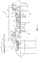
- FIG. 1 schematically illustrates a gas turbine engine 20.
- the gas turbine engine 20 is disclosed herein as a two-spool turbo fan that generally incorporates a fan section 22, a compressor section 24, a combustor section 26 and a turbine section 28.
- the fan section 22 drives air along a bypass flowpath while the compressor section 24 drives air along a core flowpath for compression and communication into the combustor section 26 then expansion through the turbine section 28.
- the concepts described herein may be applied to other turbine engine architectures such as turbojets, turboshafts, and three-spool (plus fan) turbofans.
- the engine 20 generally includes a low spool 30 and a high spool 32 mounted for rotation about an engine central longitudinal axis A relative to an engine case structure 36 via several bearing structures 38.
- the low spool 30 generally includes an inner shaft 40 that interconnects a fan 42, a low pressure compressor (“LPC”) 44 and a low pressure turbine (“LPT”) 46.
- the inner shaft 40 drives the fan 42 directly or through a geared architecture 48 to drive the fan 42 at a lower speed than the low spool 30.
- An exemplary reduction transmission is an epicyclic transmission, namely a planetary or star gear system.
- the high spool 32 includes an outer shaft 50 that interconnects a high pressure compressor (“HPC”) 52 and high pressure turbine (“HPT”) 54.
- a combustor 56 is arranged between the high pressure compressor 52 and the high pressure turbine 54.
- the inner shaft 40 and the outer shaft 50 are concentric and rotate about the engine central longitudinal axis A which is collinear with their longitudinal axes.
- Core flow is compressed by the LPC 44 then the HPC 52, mixed with the fuel and burned in the combustor 56, then the combustion gasses are expanded over the HPT 54 and the LPT 46.
- the turbines 46, 54 rotationally drive the respective low spool 30 and high spool 32 in response to the expansion.
- the main engine shafts 40, 50 are supported at a plurality of points by bearing assemblies 38 within the engine case structure 36.
- a full ring shroud assembly 60 within the engine case structure 36 supports a blade outer air seal (BOAS) assembly 62.
- the blade outer air seal (BOAS) assembly 62 contains a multiple of circumferentially distributed BOAS 64 proximate to a rotor assembly 66.
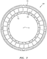
- the full ring shroud assembly 60 and the blade outer air seal (BOAS) assembly 62 are axially disposed adjacent to a first stationary vane ring 68 (also shown in FIG 3 ).
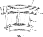
- the vane ring 68 includes an array of vanes 70 between a respective inner vane platform 72 and an outer vane platform 74.
- the array of vanes 70 are formed as a multiple of vane doublets 75 (one shown in FIG. 4 ), however, other turbine components, singlets, vanes and other components will benefit herefrom.
- the outer vane platform 74 attach the vane ring 68 to the engine case structure 36.
- the single rotor assembly 66 and the single stationary vane ring 68 are described in detail as representative of any number of multiple engine stages.
- the first stationary vane ring 68 may be mounted to the engine case structure 36 by a multiple of segmented hooked rails 76 that extend from the outer vane platform 74.
- a full hoop inner air seal 78 that attaches to the inner vane platform 72 provides a seal surface for a full hoop cover plate 80 mounted to each rotor assembly 66.
- the full hoop inner air seal 78 includes a multiple of feed passages 82 that supply cooling air "C" to an airfoil cooling circuit 84 distributed within each respective vane 70.
- Each vane 70 receives the cooling air "C" from multiple of feed passages 82 that feeds a plenum 86 thence into each airfoil cooling circuit 84.
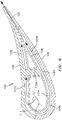
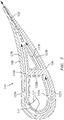
- one disclosed embodiment of the vane 70 includes an airfoil 100 that defines a blade chord between a leading edge 102, which may include various forward and/or aft sweep configurations, and a trailing edge 104.
- a first sidewall 106 that may be concave to define a pressure side
- a second sidewall 108 that may be convex to define a suction side, are joined at the leading edge 102 and at the axially spaced trailing edge 104 to create an internal cavity 107.
- An interleaved structural rib 130 extends between the first sidewall 106 and the second sidewall 108, supporting the first and second sidewalls 106, 108 and dividing the internal cavity 107 into a forward cavity 107A and an aft cavity 107B.
- a multiple of pedestals 105 may be located toward the trailing edge 104 to provide further support thereof.
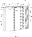
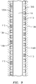
- the first sidewall 106 and the second sidewall 108 may include a multiple of standoff features 110 ( FIG. 9 ) such as cylindrical pin fins, racetrack pin fins, spherical bumps, or ribs that support and position a baffle 112 within the internal cavity 107.
- the baffle 112 provides a conduit through which flow, electrical wires, or other may be directed span wise through the airfoil 100.
- the baffle 112 includes a forward section 112A and an aft section 112B adjacent to the interleaved structural rib 130.
- Cooling air "C" from the baffle 112A is ejected through apertures 114 in a leading edge 102 of the baffle 112A which then flows around the leading edge 102 of baffle 112A and between the sidewalls 106, 108 and baffle sections 112A, 112B until ejected through the trailing edge apertures 120 ( FIG. 6 and 7 ).
- Other apertures may alternatively or additionally be provided to feed the cooling air into the space between the baffle 112 and the sidewalls 106, 108.
- FIG. 8 shows that the interleaved structural rib 130 is manufactured of a first multiple of structural rib span segments 130A that extend from the first sidewall 106 and a second multiple of structural rib span segments 130B that extend from the second sidewall 108.
- the first multiple of structural rib span segments 130A are interleaved with the second multiple of structural rib span segments 130B such that the first multiple of structural rib span segments 130A stop short of the second sidewall 108 and the second multiple of structural rib span segments 130B stop short of the first sidewall 106.
- the first sidewall 106 is tied to the second sidewall 108 thru the solidly joined interface 131 between the first multiple of structural rib span segments 130A and the second multiple of structural rib span segments 130B, preventing the thin sidewalls 106,108 from bulging.
- the interleaved structural rib 130 provides staggered axial crossover passages 116 ( FIG. 8 ) adjacent to the respective sidewalls 106, 108. Due to the interleave, the axial crossover passages 116A adjacent to the first sidewall 106 are offset span wise from the axial passages 116B adjacent to the second sidewall 108.
- the standoff features that support the baffle 112 are axial standoff ribs 110A, 110B that extend between the leading edge 102 and the trailing edge 104.
- the axial standoff ribs 110A, 110B are also staggered span wise to minimize impediment of the cooling flow travelling axially from the leading edge 102 to the trailing edge 104.
- the interleaved structural rib 130 forms the staggered axial crossover passages 116 such that the axial standoff ribs 110A, 110B correspond therewith ( FIG. 9 ).
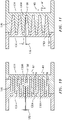
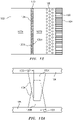
- the first and second multiple of structural rib span segments 130A, 130B include a draft angle 132 between 1-5 degrees ( FIG. 10, 11 ) to facilitate the interleave thereof.
- the draft angle will control the number and size of axial crossover passages 116. Adjacent to the corresponding axial crossover passage 116, the width W1 of the first and second structural rib span segments 130A, 130B will be larger than the width W2 of the axial crossover passages 116 due to draft angle, which may result in blockage greater than 50%. That is, because draft angles are required on some surfaces of the core die so that the core die can be separated without being hung up on the ceramic core, the distance W1 between the crossover holes will always be larger than the size W2 of the crossover hole, resulting in blockages that are greater than 50%.
- leading edge and trailing edge draft angles 133 on the first and second multiple of structural rib span segments 130A, 130B that form the interleaved structural rib 130 result in the interleaved structural rib 130 having a wavy or corrugated surface 134 ( FIG. 12 and 12A ).
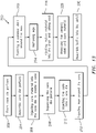
- a method 200 for manufacturing the vane with the interleaved structural rib 130 initially includes forming a core die as two halves (202).
- One half of the core die includes the pressure side wall complete with pressure side half of trailing edge pedestals, heat transfer features, axial standoff ribs and the first multiple of structural rib span segments 130A that extend from the first sidewall 106.
- the other half of the die includes the suction side wall complete with suction side half of trailing edge pedestals, heat transfer features, axial standoff ribs, and the second multiple of structural rib span segments 130B that extend from the second sidewall 108.
- the core halves are assembled to form the interleaved structural rib 130 (204).
- the parting line 136 between halves of the core die zig-zags ( FIG. 11 ) between the pressure side crossover passages 116A and the suction side crossover passages 116B.
- the core material is injected into the core die around the structural rib span segments 130A, 130B (206).
- the core die halves are separated (208) which leaves a ceramic core with the associated axial crossover passages 116 connecting the core representing the first cavity 107A to the core representing the second cavity 107B. Because the parting line 136 of the core die zig-zags between the pressure side crossover passages and the suction side crossover passages, the halves of the core die can be pulled apart without being trapped by the core.
- the core is inserted into a wax die (210) and wax is injected (212) around the core.
- the waxed core is removed from the wax die and a ceramic shell is formed around the wax (222).
- the shell and the core define a mold to cast complex exterior and interior geometries and may be formed of refractory metals, ceramic, or hybrids thereof.
- the core forms the internal surfaces such as that which defines the multiple of axial standoff ribs 110 and the interleaved structural rib 130. That is, during the casting process, the core fills a selected volume within the shell that, when removed from the finished casting, defines the array of internal passageways utilized for cooling flow.
- the wax is removed (224) and a desired material, that may include but not be limited to a nickel based superalloy, cobalt based superalloy, iron based superalloy, and mixtures thereof, is injected into the mold (226). Finally, the desired material is allowed to cool and the ceramic shell and core material is removed (228). After removal the baffle 112 is assembled into the airfoil 100 (230). It should be appreciated that other steps may alternatively or additionally be provided. Alternatively, or in addition, a single crystal starter seed or grain selector may be utilized to enable a single crystal to form when solidifying the component. The solidification may utilize a chill block in a directional solidification furnace.
- the directional solidification furnace has a hot zone that may be induction heated and a cold zone separated by an isolation valve.
- the chill block may be elevated into the hot zone and filled with molten super alloy. Casting is typically performed under an inert atmosphere or vacuum to preserve the purity of the casting.
- the vane may be formed via an additive manufacturing process (which is however not claimed).
- the additive manufacturing process sequentially builds-up layers of materials material that include but are not limited to, various titanium alloys including Ti 6-4, Inconel 625 Alloy, Inconel 718 Alloy, Haynes230 Alloy, stainless steel, tool steel, cobalt chrome, titanium, nickel, aluminum, ceramics, plastics and others in atomized powder material form.
- the starting materials can be non-atomized powders, filled or unfilled resins in liquid, solid or semisolid forms, and wire-based approaches such as wire arc for metals and Fused Deposition Modeling (FDM) for polymers.
- FDM Fused Deposition Modeling
- Alloys such as Inconel 625, Inconel 718 and Haynes 230 may have specific benefit for high temperature environments, such as, for example, environments typically encountered by aerospace and gas turbine engine articles.
- the additive manufacturing processes include, but are not limited to, SFF processes, 3-D printing methods, Sanders Modelmaker, Selective Laser Sintering (SLS), 3D systems thermoj et, ZCorp 3D printing Binder jetting, Extrude ProMetal 3D printing, stereolithography, Layered Object Manufacturing (LOM), Fused Deposition Modeling (FDDM), Electron Beam Sintering (EBS), Direct Metal Laser Sintering (DMLS), Electron Beam Melting (EBM), Electron Beam Powder Bed Fusion (EB-PBF), Electron Beam Powder Wire (EBW), Laser Engineered Net Shaping (LENS), Laser Net Shape Manufacturing (LNSM), Direct Metal Deposition (DMD), Laser Powder Bed Fusion (L-PBF), Digital Light Synthesis TM and Continuous Liquid Interface Production (CLIP TM ).
- the geometry provides the stiffness required to prevent airfoil bulge while allowing cooling flow to travel axially from the leading edge to trailing edge with minimal pressure loss.
Landscapes
- Engineering & Computer Science (AREA)
- Mechanical Engineering (AREA)
- General Engineering & Computer Science (AREA)
- Turbine Rotor Nozzle Sealing (AREA)
Claims (11)
- Aube (70) pour un moteur à turbine à gaz (20), comprenant :une première paroi latérale (106) ;un premier multiple de segments de portée de nervure structurale (130A) qui s'étendent à partir de la première paroi latérale (106) ;une seconde paroi latérale (108) ; etun second multiple de segments de portée de nervure structurale (130B) qui s'étendent à partir de la seconde paroi latérale (108), le premier multiple de segments de portée de nervure structurale (130A) étant entrelacé avec le second multiple de segments de portée de nervure structurale (130B) pour former une nervure structurale entrelacée (130) qui s'étend entre la première paroi latérale (106) et la seconde paroi latérale (108), caractérisée en ce que :la nervure structurale entrelacée (130) et les première et seconde parois latérales (106, 108) forment un multiple de passages de croisement axiaux (116A, 116B), dans laquelle le multiple de passages de croisement axiaux (116A, 116B) comporte en outre un premier multiple de passages de croisement axiaux (116A) adjacents à la première paroi latérale (106) et un second multiple de passages de croisement axiaux (116B) adjacents à la seconde paroi latérale (108), dans lequel le second multiple de passages de croisement axiaux (116B) est décalé par rapport au premier multiple de passages de croisement axiaux (116A) ; etles premier et second multiples de segments de portée de nervure structurale (130A, 130B) comportent un angle de dépouille (132) compris entre 1° et 5° pour faciliter l'entrelacement du premier multiple de segments de portée de nervure structurale (130A) avec le second multiple de segments de portée de nervure structurale (130B).
- Aube (70) selon la revendication 1, comprenant en outre un déflecteur (112) adjacent à la nervure structurale entrelacée (130).
- Aube (70) selon la revendication 1 ou 2, dans laquelle la première paroi latérale (106) est un côté intrados et la seconde paroi latérale (108) est un côté extrados d'un profil aérodynamique (100).
- Aube (70) selon une quelconque revendication précédente, dans laquelle la première paroi latérale (106) et la seconde paroi latérale (108) s'étendent entre une plate-forme d'aube extérieure (74) et une plate-forme d'aube intérieure (72) .
- Aube (70) selon une quelconque revendication précédente, dans laquelle la nervure structurale entrelacée (130) s'étend entre une ou la plate-forme d'aube extérieure (74) et une ou la plate-forme d'aube intérieure (72).
- Aube (70) selon une quelconque revendication précédente, comprenant en outre un premier multiple de nervures d'écartement axiales (110) s'étendant à partir de la première paroi latérale (106) et un second multiple de nervures d'écartement axiales (110) s'étendant à partir de la seconde paroi latérale (108), dans laquelle chacun du premier multiple de nervures d'écartement axiales (110) est décalé par rapport à chacun du second multiple de nervures d'écartement axiales (110).
- Aube (70) selon une quelconque revendication précédente, dans laquelle la nervure structurale entrelacée (130) est ondulée.
- Aube (70) selon une quelconque revendication précédente, dans laquelle chacun du multiple de passages de croisement axiaux (116A, 116B) relie une cavité avant (107A) à une cavité arrière (107B) de l'aube (70).
- Aube (70) selon une quelconque revendication précédente, dans laquelle une distance entre chacun du premier multiple de passages de croisement axiaux (116A) est supérieure à une taille d'un du premier multiple de passages de croisement axiaux (116A), et une distance (W1) entre chacun du second multiple de passages de croisement axiaux (116B) est supérieure à une taille (W2) d'un du second multiple de passages de croisement axiaux (116B).
- Aube (70) selon une quelconque revendication précédente, comprenant en outre une section de déflecteur avant (112A) adjacente à la nervure structurale entrelacée (130) et une section de déflecteur arrière (112B) adjacente à la nervure structurale entrelacée (130).
- Procédé de fabrication d'une aube (70) d'un moteur à turbine à gaz (20), le procédé comprenant :la formation d'une première partie de matrice de noyau avec un premier multiple de segments de portée de nervure structurale (130A) qui s'étendent à partir d'une première paroi latérale (106) ;la formation d'une seconde partie de matrice de noyau avec un second multiple de segments de portée de nervure structurale (130B) qui s'étendent à partir d'une seconde paroi latérale (108) ;l'assemblage de la première partie de matrice de noyau et de la seconde partie de matrice de noyau de sorte que le premier multiple de segments de portée de nervure structurale (130A) soit entrelacé avec le second multiple de segments de portée de nervure structurale (130B) pour former une nervure structurale entrelacée (130) ;l'injection du matériau de noyau dans la matrice de noyau pour créer un noyau ;la séparation des parties de matrice de noyau ;l'insertion du noyau dans une matrice en cire ;l'injection de la cire autour du noyau ;la formation d'une coque en céramique autour de la cire ;le retrait de la cire ;l'injection de matière fondue dans la coque et le fait de laisser refroidir ; etle retrait de la coque en céramique et du matériau de noyau, caractérisé en ce que :le procédé crée un premier multiple de passages de croisement axiaux (116A) sur un premier côté et un second multiple de passages de croisement axiaux (116B) sur un second côté, le premier multiple de passages de croisement axiaux (116A) étant décalé par rapport au second multiple de passages de croisement axiaux (116B) ;une ligne de séparation (136) entre la première partie de matrice de noyau et la seconde partie de matrice de noyau en zigzag entre le premier multiple de passages de croisement axiaux (116A) et le second multiple de passages de croisement axiaux (116B) ; etun angle de dépouille (132) sur les surfaces du premier multiple de segments de portée de nervure structurale (130A) et les surfaces du second multiple de segments de portée de nervure structurale (130B) est compris entre 1 et 5 degrés.
Applications Claiming Priority (1)
| Application Number | Priority Date | Filing Date | Title |
|---|---|---|---|
| US16/210,696 US10822963B2 (en) | 2018-12-05 | 2018-12-05 | Axial flow cooling scheme with castable structural rib for a gas turbine engine |
Publications (2)
| Publication Number | Publication Date |
|---|---|
| EP3663525A1 EP3663525A1 (fr) | 2020-06-10 |
| EP3663525B1 true EP3663525B1 (fr) | 2022-11-09 |
Family
ID=68808079
Family Applications (1)
| Application Number | Title | Priority Date | Filing Date |
|---|---|---|---|
| EP19213973.1A Active EP3663525B1 (fr) | 2018-12-05 | 2019-12-05 | Schéma de refroidissement à flux axial avec nervure structurale pouvant être moulée pour un moteur à turbine à gaz |
Country Status (2)
| Country | Link |
|---|---|
| US (1) | US10822963B2 (fr) |
| EP (1) | EP3663525B1 (fr) |
Families Citing this family (8)
| Publication number | Priority date | Publication date | Assignee | Title |
|---|---|---|---|---|
| WO2015126488A2 (fr) * | 2013-12-23 | 2015-08-27 | United Technologies Corporation | Cadre structural à noyau perdu |
| US11434772B2 (en) * | 2020-09-29 | 2022-09-06 | General Electric Company | Turbine nozzle and method of manufacture |
| US12371996B2 (en) | 2021-08-06 | 2025-07-29 | Rtx Corporation | Hybrid supply configuration for axially flowing high internal mach number baffles |
| US11920794B1 (en) | 2022-12-15 | 2024-03-05 | Ge Infrastructure Technology Llc | Combustor having thermally compliant bundled tube fuel nozzle |
| US11939878B1 (en) | 2022-12-15 | 2024-03-26 | Ge Infrastructure Technology Llc | Turbomachine component having self-breaking supports |
| US12215601B2 (en) | 2023-02-17 | 2025-02-04 | Rtx Corporation | Air foil with staggered cooling hole configuration |
| CN119737198B (zh) * | 2024-12-26 | 2026-03-10 | 东方电气集团东方汽轮机有限公司 | 带雾化冷却耦合折板结构的双层壁燃气轮机叶片及方法 |
| US12571318B1 (en) * | 2025-04-24 | 2026-03-10 | Ge Vernova Infrastructure Technology Llc | Airfoil having flex elements with multi-dimensional curvature |
Family Cites Families (25)
| Publication number | Priority date | Publication date | Assignee | Title |
|---|---|---|---|---|
| GB1034260A (en) | 1964-12-02 | 1966-06-29 | Rolls Royce | Aerofoil-shaped blade for use in a fluid flow machine |
| BE755567A (fr) | 1969-12-01 | 1971-02-15 | Gen Electric | Structure d'aube fixe, pour moteur a turbines a gaz et arrangement de reglage de temperature associe |
| GB1304678A (fr) | 1971-06-30 | 1973-01-24 | ||
| GB1361256A (en) * | 1971-08-25 | 1974-07-24 | Rolls Royce | Gas turbine engine blades |
| GB2096525B (en) | 1981-04-14 | 1984-09-12 | Rolls Royce | Manufacturing gas turbine engine blades |
| JPS61118501A (ja) | 1984-11-15 | 1986-06-05 | Toshiba Corp | ガスタ−ビンの羽根 |
| SE512384C2 (sv) * | 1998-05-25 | 2000-03-06 | Abb Ab | Komponent för en gasturbin |
| EP1136651A1 (fr) | 2000-03-22 | 2001-09-26 | Siemens Aktiengesellschaft | Système de refroidissement pour une aube de turbine à gaz |
| US6428273B1 (en) | 2001-01-05 | 2002-08-06 | General Electric Company | Truncated rib turbine nozzle |
| GB0127902D0 (en) | 2001-11-21 | 2002-01-16 | Rolls Royce Plc | Gas turbine engine aerofoil |
| US6742991B2 (en) | 2002-07-11 | 2004-06-01 | Mitsubishi Heavy Industries, Ltd. | Turbine blade and gas turbine |
| SE526847C2 (sv) * | 2004-02-27 | 2005-11-08 | Demag Delaval Ind Turbomachine | En komponent som innefattar en ledskena eller ett rotorblad för en gasturbin |
| US7322796B2 (en) | 2005-08-31 | 2008-01-29 | United Technologies Corporation | Turbine vane construction |
| US7497655B1 (en) | 2006-08-21 | 2009-03-03 | Florida Turbine Technologies, Inc. | Turbine airfoil with near-wall impingement and vortex cooling |
| US8757974B2 (en) | 2007-01-11 | 2014-06-24 | United Technologies Corporation | Cooling circuit flow path for a turbine section airfoil |
| US8210814B2 (en) | 2008-06-18 | 2012-07-03 | General Electric Company | Crossflow turbine airfoil |
| US8348613B2 (en) | 2009-03-30 | 2013-01-08 | United Technologies Corporation | Airflow influencing airfoil feature array |
| EP2378073A1 (fr) * | 2010-04-14 | 2011-10-19 | Siemens Aktiengesellschaft | Aube de rotor ou de stator pour turbomachine |
| WO2013077761A1 (fr) | 2011-11-25 | 2013-05-30 | Siemens Aktiengesellschaft | Profil aérodynamique à passages de refroidissement |
| EP2628901A1 (fr) | 2012-02-15 | 2013-08-21 | Siemens Aktiengesellschaft | Aube de turbine à gaz avec refroidissement par impact |
| US20140075947A1 (en) | 2012-09-18 | 2014-03-20 | United Technologies Corporation | Gas turbine engine component cooling circuit |
| WO2015012918A2 (fr) | 2013-06-04 | 2015-01-29 | United Technologies Corporation | Refroidissement du côté aspiration de bord de fuite de surface portante pour à turbine à gaz |
| CN106661945A (zh) | 2014-09-04 | 2017-05-10 | 西门子公司 | 带有在燃气涡轮翼型的尾部冷却腔中形成近壁冷却通道的插入件的内部冷却系统 |
| WO2016148690A1 (fr) * | 2015-03-17 | 2016-09-22 | Siemens Energy, Inc. | Aube de turbine avec structure de guidage tournante à écoulement sans contrainte |
| US10648341B2 (en) | 2016-11-15 | 2020-05-12 | Rolls-Royce Corporation | Airfoil leading edge impingement cooling |
-
2018
- 2018-12-05 US US16/210,696 patent/US10822963B2/en active Active
-
2019
- 2019-12-05 EP EP19213973.1A patent/EP3663525B1/fr active Active
Also Published As
| Publication number | Publication date |
|---|---|
| US20200182069A1 (en) | 2020-06-11 |
| US10822963B2 (en) | 2020-11-03 |
| EP3663525A1 (fr) | 2020-06-10 |
Similar Documents
| Publication | Publication Date | Title |
|---|---|---|
| US10822963B2 (en) | Axial flow cooling scheme with castable structural rib for a gas turbine engine | |
| EP2947184B1 (fr) | Procédé permettant de former des composants à l'aide de refonte et de fabrication additive | |
| US11059093B2 (en) | Additively manufactured core for use in casting an internal cooling circuit of a gas turbine engine component | |
| EP2942424B1 (fr) | Procédé de formation d'un corps de remplacement solidifié de manière directionnelle pour un composant à l'aide de fabrication additive | |
| US11766722B2 (en) | Method for the hybrid construction of multi-piece parts | |
| US11236621B2 (en) | Method for forming single crystal components using additive manufacturing and re-melt | |
| US9718127B2 (en) | Method for forming components using additive manufacturing and re-melt | |
| US10247015B2 (en) | Cooled blisk with dual wall blades for gas turbine engine | |
| US10934865B2 (en) | Cooled single walled blisk for gas turbine engine | |
| CN110735665B (zh) | 具有可调节冷却构造的翼型件 | |
| US10226812B2 (en) | Additively manufactured core for use in casting an internal cooling circuit of a gas turbine engine component | |
| EP3633150B2 (fr) | Noyau de surface portante à plusieurs parois | |
| US10619852B2 (en) | Heat shield with round top pin fins and flat top pin fins for improved manufacturing processes | |
| EP3663524B1 (fr) | Schéma de refroidissement à flux axial avec nervure structurale pour un moteur à turbine à gaz | |
| US11753942B1 (en) | Frangible airfoils |
Legal Events
| Date | Code | Title | Description |
|---|---|---|---|
| PUAI | Public reference made under article 153(3) epc to a published international application that has entered the european phase |
Free format text: ORIGINAL CODE: 0009012 |
|
| STAA | Information on the status of an ep patent application or granted ep patent |
Free format text: STATUS: THE APPLICATION HAS BEEN PUBLISHED |
|
| AK | Designated contracting states |
Kind code of ref document: A1 Designated state(s): AL AT BE BG CH CY CZ DE DK EE ES FI FR GB GR HR HU IE IS IT LI LT LU LV MC MK MT NL NO PL PT RO RS SE SI SK SM TR |
|
| AX | Request for extension of the european patent |
Extension state: BA ME |
|
| STAA | Information on the status of an ep patent application or granted ep patent |
Free format text: STATUS: REQUEST FOR EXAMINATION WAS MADE |
|
| 17P | Request for examination filed |
Effective date: 20201210 |
|
| RBV | Designated contracting states (corrected) |
Designated state(s): AL AT BE BG CH CY CZ DE DK EE ES FI FR GB GR HR HU IE IS IT LI LT LU LV MC MK MT NL NO PL PT RO RS SE SI SK SM TR |
|
| RAP1 | Party data changed (applicant data changed or rights of an application transferred) |
Owner name: RAYTHEON TECHNOLOGIES CORPORATION |
|
| GRAP | Despatch of communication of intention to grant a patent |
Free format text: ORIGINAL CODE: EPIDOSNIGR1 |
|
| STAA | Information on the status of an ep patent application or granted ep patent |
Free format text: STATUS: GRANT OF PATENT IS INTENDED |
|
| RIC1 | Information provided on ipc code assigned before grant |
Ipc: F01D 9/02 20060101ALI20220503BHEP Ipc: F01D 5/18 20060101AFI20220503BHEP |
|
| INTG | Intention to grant announced |
Effective date: 20220524 |
|
| GRAS | Grant fee paid |
Free format text: ORIGINAL CODE: EPIDOSNIGR3 |
|
| GRAA | (expected) grant |
Free format text: ORIGINAL CODE: 0009210 |
|
| STAA | Information on the status of an ep patent application or granted ep patent |
Free format text: STATUS: THE PATENT HAS BEEN GRANTED |
|
| AK | Designated contracting states |
Kind code of ref document: B1 Designated state(s): AL AT BE BG CH CY CZ DE DK EE ES FI FR GB GR HR HU IE IS IT LI LT LU LV MC MK MT NL NO PL PT RO RS SE SI SK SM TR |
|
| REG | Reference to a national code |
Ref country code: GB Ref legal event code: FG4D |
|
| REG | Reference to a national code |
Ref country code: CH Ref legal event code: EP Ref country code: AT Ref legal event code: REF Ref document number: 1530501 Country of ref document: AT Kind code of ref document: T Effective date: 20221115 |
|
| REG | Reference to a national code |
Ref country code: DE Ref legal event code: R096 Ref document number: 602019021659 Country of ref document: DE |
|
| REG | Reference to a national code |
Ref country code: IE Ref legal event code: FG4D |
|
| REG | Reference to a national code |
Ref country code: LT Ref legal event code: MG9D |
|
| REG | Reference to a national code |
Ref country code: NL Ref legal event code: MP Effective date: 20221109 |
|
| REG | Reference to a national code |
Ref country code: AT Ref legal event code: MK05 Ref document number: 1530501 Country of ref document: AT Kind code of ref document: T Effective date: 20221109 |
|
| PG25 | Lapsed in a contracting state [announced via postgrant information from national office to epo] |
Ref country code: SE Free format text: LAPSE BECAUSE OF FAILURE TO SUBMIT A TRANSLATION OF THE DESCRIPTION OR TO PAY THE FEE WITHIN THE PRESCRIBED TIME-LIMIT Effective date: 20221109 Ref country code: PT Free format text: LAPSE BECAUSE OF FAILURE TO SUBMIT A TRANSLATION OF THE DESCRIPTION OR TO PAY THE FEE WITHIN THE PRESCRIBED TIME-LIMIT Effective date: 20230309 Ref country code: NO Free format text: LAPSE BECAUSE OF FAILURE TO SUBMIT A TRANSLATION OF THE DESCRIPTION OR TO PAY THE FEE WITHIN THE PRESCRIBED TIME-LIMIT Effective date: 20230209 Ref country code: LT Free format text: LAPSE BECAUSE OF FAILURE TO SUBMIT A TRANSLATION OF THE DESCRIPTION OR TO PAY THE FEE WITHIN THE PRESCRIBED TIME-LIMIT Effective date: 20221109 Ref country code: FI Free format text: LAPSE BECAUSE OF FAILURE TO SUBMIT A TRANSLATION OF THE DESCRIPTION OR TO PAY THE FEE WITHIN THE PRESCRIBED TIME-LIMIT Effective date: 20221109 Ref country code: ES Free format text: LAPSE BECAUSE OF FAILURE TO SUBMIT A TRANSLATION OF THE DESCRIPTION OR TO PAY THE FEE WITHIN THE PRESCRIBED TIME-LIMIT Effective date: 20221109 Ref country code: AT Free format text: LAPSE BECAUSE OF FAILURE TO SUBMIT A TRANSLATION OF THE DESCRIPTION OR TO PAY THE FEE WITHIN THE PRESCRIBED TIME-LIMIT Effective date: 20221109 |
|
| PG25 | Lapsed in a contracting state [announced via postgrant information from national office to epo] |
Ref country code: RS Free format text: LAPSE BECAUSE OF FAILURE TO SUBMIT A TRANSLATION OF THE DESCRIPTION OR TO PAY THE FEE WITHIN THE PRESCRIBED TIME-LIMIT Effective date: 20221109 Ref country code: PL Free format text: LAPSE BECAUSE OF FAILURE TO SUBMIT A TRANSLATION OF THE DESCRIPTION OR TO PAY THE FEE WITHIN THE PRESCRIBED TIME-LIMIT Effective date: 20221109 Ref country code: LV Free format text: LAPSE BECAUSE OF FAILURE TO SUBMIT A TRANSLATION OF THE DESCRIPTION OR TO PAY THE FEE WITHIN THE PRESCRIBED TIME-LIMIT Effective date: 20221109 Ref country code: IS Free format text: LAPSE BECAUSE OF FAILURE TO SUBMIT A TRANSLATION OF THE DESCRIPTION OR TO PAY THE FEE WITHIN THE PRESCRIBED TIME-LIMIT Effective date: 20230309 Ref country code: HR Free format text: LAPSE BECAUSE OF FAILURE TO SUBMIT A TRANSLATION OF THE DESCRIPTION OR TO PAY THE FEE WITHIN THE PRESCRIBED TIME-LIMIT Effective date: 20221109 Ref country code: GR Free format text: LAPSE BECAUSE OF FAILURE TO SUBMIT A TRANSLATION OF THE DESCRIPTION OR TO PAY THE FEE WITHIN THE PRESCRIBED TIME-LIMIT Effective date: 20230210 |
|
| P01 | Opt-out of the competence of the unified patent court (upc) registered |
Effective date: 20230521 |
|
| PG25 | Lapsed in a contracting state [announced via postgrant information from national office to epo] |
Ref country code: NL Free format text: LAPSE BECAUSE OF FAILURE TO SUBMIT A TRANSLATION OF THE DESCRIPTION OR TO PAY THE FEE WITHIN THE PRESCRIBED TIME-LIMIT Effective date: 20221109 |
|
| PG25 | Lapsed in a contracting state [announced via postgrant information from national office to epo] |
Ref country code: SM Free format text: LAPSE BECAUSE OF FAILURE TO SUBMIT A TRANSLATION OF THE DESCRIPTION OR TO PAY THE FEE WITHIN THE PRESCRIBED TIME-LIMIT Effective date: 20221109 Ref country code: RO Free format text: LAPSE BECAUSE OF FAILURE TO SUBMIT A TRANSLATION OF THE DESCRIPTION OR TO PAY THE FEE WITHIN THE PRESCRIBED TIME-LIMIT Effective date: 20221109 Ref country code: EE Free format text: LAPSE BECAUSE OF FAILURE TO SUBMIT A TRANSLATION OF THE DESCRIPTION OR TO PAY THE FEE WITHIN THE PRESCRIBED TIME-LIMIT Effective date: 20221109 Ref country code: DK Free format text: LAPSE BECAUSE OF FAILURE TO SUBMIT A TRANSLATION OF THE DESCRIPTION OR TO PAY THE FEE WITHIN THE PRESCRIBED TIME-LIMIT Effective date: 20221109 Ref country code: CZ Free format text: LAPSE BECAUSE OF FAILURE TO SUBMIT A TRANSLATION OF THE DESCRIPTION OR TO PAY THE FEE WITHIN THE PRESCRIBED TIME-LIMIT Effective date: 20221109 |
|
| REG | Reference to a national code |
Ref country code: CH Ref legal event code: PL |
|
| REG | Reference to a national code |
Ref country code: DE Ref legal event code: R097 Ref document number: 602019021659 Country of ref document: DE |
|
| REG | Reference to a national code |
Ref country code: BE Ref legal event code: MM Effective date: 20221231 |
|
| PG25 | Lapsed in a contracting state [announced via postgrant information from national office to epo] |
Ref country code: SK Free format text: LAPSE BECAUSE OF FAILURE TO SUBMIT A TRANSLATION OF THE DESCRIPTION OR TO PAY THE FEE WITHIN THE PRESCRIBED TIME-LIMIT Effective date: 20221109 Ref country code: LU Free format text: LAPSE BECAUSE OF NON-PAYMENT OF DUE FEES Effective date: 20221205 Ref country code: AL Free format text: LAPSE BECAUSE OF FAILURE TO SUBMIT A TRANSLATION OF THE DESCRIPTION OR TO PAY THE FEE WITHIN THE PRESCRIBED TIME-LIMIT Effective date: 20221109 |
|
| PLBE | No opposition filed within time limit |
Free format text: ORIGINAL CODE: 0009261 |
|
| STAA | Information on the status of an ep patent application or granted ep patent |
Free format text: STATUS: NO OPPOSITION FILED WITHIN TIME LIMIT |
|
| 26N | No opposition filed |
Effective date: 20230810 |
|
| PG25 | Lapsed in a contracting state [announced via postgrant information from national office to epo] |
Ref country code: LI Free format text: LAPSE BECAUSE OF NON-PAYMENT OF DUE FEES Effective date: 20221231 Ref country code: IE Free format text: LAPSE BECAUSE OF NON-PAYMENT OF DUE FEES Effective date: 20221205 Ref country code: CH Free format text: LAPSE BECAUSE OF NON-PAYMENT OF DUE FEES Effective date: 20221231 |
|
| PG25 | Lapsed in a contracting state [announced via postgrant information from national office to epo] |
Ref country code: SI Free format text: LAPSE BECAUSE OF FAILURE TO SUBMIT A TRANSLATION OF THE DESCRIPTION OR TO PAY THE FEE WITHIN THE PRESCRIBED TIME-LIMIT Effective date: 20221109 Ref country code: BE Free format text: LAPSE BECAUSE OF NON-PAYMENT OF DUE FEES Effective date: 20221231 |
|
| PG25 | Lapsed in a contracting state [announced via postgrant information from national office to epo] |
Ref country code: HU Free format text: LAPSE BECAUSE OF FAILURE TO SUBMIT A TRANSLATION OF THE DESCRIPTION OR TO PAY THE FEE WITHIN THE PRESCRIBED TIME-LIMIT; INVALID AB INITIO Effective date: 20191205 |
|
| PG25 | Lapsed in a contracting state [announced via postgrant information from national office to epo] |
Ref country code: CY Free format text: LAPSE BECAUSE OF FAILURE TO SUBMIT A TRANSLATION OF THE DESCRIPTION OR TO PAY THE FEE WITHIN THE PRESCRIBED TIME-LIMIT Effective date: 20221109 |
|
| PG25 | Lapsed in a contracting state [announced via postgrant information from national office to epo] |
Ref country code: MK Free format text: LAPSE BECAUSE OF FAILURE TO SUBMIT A TRANSLATION OF THE DESCRIPTION OR TO PAY THE FEE WITHIN THE PRESCRIBED TIME-LIMIT Effective date: 20221109 Ref country code: IT Free format text: LAPSE BECAUSE OF FAILURE TO SUBMIT A TRANSLATION OF THE DESCRIPTION OR TO PAY THE FEE WITHIN THE PRESCRIBED TIME-LIMIT Effective date: 20221109 |
|
| PG25 | Lapsed in a contracting state [announced via postgrant information from national office to epo] |
Ref country code: MC Free format text: LAPSE BECAUSE OF FAILURE TO SUBMIT A TRANSLATION OF THE DESCRIPTION OR TO PAY THE FEE WITHIN THE PRESCRIBED TIME-LIMIT Effective date: 20221109 |
|
| PG25 | Lapsed in a contracting state [announced via postgrant information from national office to epo] |
Ref country code: TR Free format text: LAPSE BECAUSE OF FAILURE TO SUBMIT A TRANSLATION OF THE DESCRIPTION OR TO PAY THE FEE WITHIN THE PRESCRIBED TIME-LIMIT Effective date: 20221109 Ref country code: MC Free format text: LAPSE BECAUSE OF FAILURE TO SUBMIT A TRANSLATION OF THE DESCRIPTION OR TO PAY THE FEE WITHIN THE PRESCRIBED TIME-LIMIT Effective date: 20221109 |
|
| PG25 | Lapsed in a contracting state [announced via postgrant information from national office to epo] |
Ref country code: BG Free format text: LAPSE BECAUSE OF FAILURE TO SUBMIT A TRANSLATION OF THE DESCRIPTION OR TO PAY THE FEE WITHIN THE PRESCRIBED TIME-LIMIT Effective date: 20221109 |
|
| PG25 | Lapsed in a contracting state [announced via postgrant information from national office to epo] |
Ref country code: MT Free format text: LAPSE BECAUSE OF FAILURE TO SUBMIT A TRANSLATION OF THE DESCRIPTION OR TO PAY THE FEE WITHIN THE PRESCRIBED TIME-LIMIT Effective date: 20221109 |
|
| REG | Reference to a national code |
Ref country code: DE Ref legal event code: R081 Ref document number: 602019021659 Country of ref document: DE Owner name: RTX CORPORATION (N.D.GES.D. STAATES DELAWARE),, US Free format text: FORMER OWNER: RAYTHEON TECHNOLOGIES CORPORATION, FARMINGTON, CT, US |
|
| PGFP | Annual fee paid to national office [announced via postgrant information from national office to epo] |
Ref country code: DE Payment date: 20251126 Year of fee payment: 7 |
|
| PGFP | Annual fee paid to national office [announced via postgrant information from national office to epo] |
Ref country code: GB Payment date: 20251119 Year of fee payment: 7 |
|
| PGFP | Annual fee paid to national office [announced via postgrant information from national office to epo] |
Ref country code: FR Payment date: 20251120 Year of fee payment: 7 |