EP3663541A1 - Wärmeverwaltungssysteme für gasturbinentriebwerk - Google Patents
Wärmeverwaltungssysteme für gasturbinentriebwerk Download PDFInfo
- Publication number
- EP3663541A1 EP3663541A1 EP19212696.9A EP19212696A EP3663541A1 EP 3663541 A1 EP3663541 A1 EP 3663541A1 EP 19212696 A EP19212696 A EP 19212696A EP 3663541 A1 EP3663541 A1 EP 3663541A1
- Authority
- EP
- European Patent Office
- Prior art keywords
- additively manufactured
- recited
- heat exchanger
- external surface
- gas turbine
- Prior art date
- Legal status (The legal status is an assumption and is not a legal conclusion. Google has not performed a legal analysis and makes no representation as to the accuracy of the status listed.)
- Granted
Links
Images


Classifications
-
- B—PERFORMING OPERATIONS; TRANSPORTING
- B64—AIRCRAFT; AVIATION; COSMONAUTICS
- B64D—EQUIPMENT FOR FITTING IN OR TO AIRCRAFT; FLIGHT SUITS; PARACHUTES; ARRANGEMENT OR MOUNTING OF POWER PLANTS OR PROPULSION TRANSMISSIONS IN AIRCRAFT
- B64D33/00—Arrangement in aircraft of power plant parts or auxiliaries not otherwise provided for
- B64D33/08—Arrangement in aircraft of power plant parts or auxiliaries not otherwise provided for of power plant cooling systems
-
- B—PERFORMING OPERATIONS; TRANSPORTING
- B22—CASTING; POWDER METALLURGY
- B22F—WORKING METALLIC POWDER; MANUFACTURE OF ARTICLES FROM METALLIC POWDER; MAKING METALLIC POWDER; APPARATUS OR DEVICES SPECIALLY ADAPTED FOR METALLIC POWDER
- B22F10/00—Additive manufacturing of workpieces or articles from metallic powder
- B22F10/20—Direct sintering or melting
-
- B—PERFORMING OPERATIONS; TRANSPORTING
- B22—CASTING; POWDER METALLURGY
- B22F—WORKING METALLIC POWDER; MANUFACTURE OF ARTICLES FROM METALLIC POWDER; MAKING METALLIC POWDER; APPARATUS OR DEVICES SPECIALLY ADAPTED FOR METALLIC POWDER
- B22F5/00—Manufacture of workpieces or articles from metallic powder characterised by the special shape of the product
- B22F5/009—Manufacture of workpieces or articles from metallic powder characterised by the special shape of the product of turbine components other than turbine blades
-
- B—PERFORMING OPERATIONS; TRANSPORTING
- B33—ADDITIVE MANUFACTURING TECHNOLOGY
- B33Y—ADDITIVE MANUFACTURING, i.e. MANUFACTURING OF THREE-DIMENSIONAL [3D] OBJECTS BY ADDITIVE DEPOSITION, ADDITIVE AGGLOMERATION OR ADDITIVE LAYERING, e.g. BY 3D PRINTING, STEREOLITHOGRAPHY OR SELECTIVE LASER SINTERING
- B33Y80/00—Products made by additive manufacturing
-
- B—PERFORMING OPERATIONS; TRANSPORTING
- B64—AIRCRAFT; AVIATION; COSMONAUTICS
- B64D—EQUIPMENT FOR FITTING IN OR TO AIRCRAFT; FLIGHT SUITS; PARACHUTES; ARRANGEMENT OR MOUNTING OF POWER PLANTS OR PROPULSION TRANSMISSIONS IN AIRCRAFT
- B64D29/00—Power-plant nacelles, fairings or cowlings
-
- B—PERFORMING OPERATIONS; TRANSPORTING
- B64—AIRCRAFT; AVIATION; COSMONAUTICS
- B64D—EQUIPMENT FOR FITTING IN OR TO AIRCRAFT; FLIGHT SUITS; PARACHUTES; ARRANGEMENT OR MOUNTING OF POWER PLANTS OR PROPULSION TRANSMISSIONS IN AIRCRAFT
- B64D29/00—Power-plant nacelles, fairings or cowlings
- B64D29/08—Inspection panels for power plants
-
- F—MECHANICAL ENGINEERING; LIGHTING; HEATING; WEAPONS; BLASTING
- F01—MACHINES OR ENGINES IN GENERAL; ENGINE PLANTS IN GENERAL; STEAM ENGINES
- F01D—NON-POSITIVE DISPLACEMENT MACHINES OR ENGINES, e.g. STEAM TURBINES
- F01D25/00—Component parts, details, or accessories, not provided for in, or of interest apart from, other groups
- F01D25/08—Cooling; Heating; Heat-insulation
- F01D25/12—Cooling
-
- F—MECHANICAL ENGINEERING; LIGHTING; HEATING; WEAPONS; BLASTING
- F01—MACHINES OR ENGINES IN GENERAL; ENGINE PLANTS IN GENERAL; STEAM ENGINES
- F01D—NON-POSITIVE DISPLACEMENT MACHINES OR ENGINES, e.g. STEAM TURBINES
- F01D25/00—Component parts, details, or accessories, not provided for in, or of interest apart from, other groups
- F01D25/08—Cooling; Heating; Heat-insulation
- F01D25/14—Casings modified therefor
-
- F—MECHANICAL ENGINEERING; LIGHTING; HEATING; WEAPONS; BLASTING
- F01—MACHINES OR ENGINES IN GENERAL; ENGINE PLANTS IN GENERAL; STEAM ENGINES
- F01D—NON-POSITIVE DISPLACEMENT MACHINES OR ENGINES, e.g. STEAM TURBINES
- F01D25/00—Component parts, details, or accessories, not provided for in, or of interest apart from, other groups
- F01D25/18—Lubricating arrangements
-
- F—MECHANICAL ENGINEERING; LIGHTING; HEATING; WEAPONS; BLASTING
- F02—COMBUSTION ENGINES; HOT-GAS OR COMBUSTION-PRODUCT ENGINE PLANTS
- F02K—JET-PROPULSION PLANTS
- F02K3/00—Plants including a gas turbine driving a compressor or a ducted fan
- F02K3/02—Plants including a gas turbine driving a compressor or a ducted fan in which part of the working fluid by-passes the turbine and combustion chamber
- F02K3/04—Plants including a gas turbine driving a compressor or a ducted fan in which part of the working fluid by-passes the turbine and combustion chamber the plant including ducted fans, i.e. fans with high volume, low pressure outputs, for augmenting the jet thrust, e.g. of double-flow type
- F02K3/06—Plants including a gas turbine driving a compressor or a ducted fan in which part of the working fluid by-passes the turbine and combustion chamber the plant including ducted fans, i.e. fans with high volume, low pressure outputs, for augmenting the jet thrust, e.g. of double-flow type with front fan
-
- F—MECHANICAL ENGINEERING; LIGHTING; HEATING; WEAPONS; BLASTING
- F28—HEAT EXCHANGE IN GENERAL
- F28D—HEAT-EXCHANGE APPARATUS, NOT PROVIDED FOR IN ANOTHER SUBCLASS, IN WHICH THE HEAT-EXCHANGE MEDIA DO NOT COME INTO DIRECT CONTACT
- F28D1/00—Heat-exchange apparatus having stationary conduit assemblies for one heat-exchange medium only, the media being in contact with different sides of the conduit wall, in which the other heat-exchange medium is a large body of fluid, e.g. domestic or motor car radiators
- F28D1/06—Heat-exchange apparatus having stationary conduit assemblies for one heat-exchange medium only, the media being in contact with different sides of the conduit wall, in which the other heat-exchange medium is a large body of fluid, e.g. domestic or motor car radiators with the heat-exchange conduits forming part of, or being attached to, the tank containing the body of fluid
-
- F—MECHANICAL ENGINEERING; LIGHTING; HEATING; WEAPONS; BLASTING
- F28—HEAT EXCHANGE IN GENERAL
- F28F—DETAILS OF HEAT-EXCHANGE AND HEAT-TRANSFER APPARATUS, OF GENERAL APPLICATION
- F28F13/00—Arrangements for modifying heat-transfer, e.g. increasing, decreasing
- F28F13/06—Arrangements for modifying heat-transfer, e.g. increasing, decreasing by affecting the pattern of flow of the heat-exchange media
- F28F13/12—Arrangements for modifying heat-transfer, e.g. increasing, decreasing by affecting the pattern of flow of the heat-exchange media by creating turbulence, e.g. by stirring, by increasing the force of circulation
-
- B—PERFORMING OPERATIONS; TRANSPORTING
- B22—CASTING; POWDER METALLURGY
- B22F—WORKING METALLIC POWDER; MANUFACTURE OF ARTICLES FROM METALLIC POWDER; MAKING METALLIC POWDER; APPARATUS OR DEVICES SPECIALLY ADAPTED FOR METALLIC POWDER
- B22F10/00—Additive manufacturing of workpieces or articles from metallic powder
- B22F10/10—Formation of a green body
- B22F10/12—Formation of a green body by photopolymerisation, e.g. stereolithography [SLA] or digital light processing [DLP]
-
- B—PERFORMING OPERATIONS; TRANSPORTING
- B22—CASTING; POWDER METALLURGY
- B22F—WORKING METALLIC POWDER; MANUFACTURE OF ARTICLES FROM METALLIC POWDER; MAKING METALLIC POWDER; APPARATUS OR DEVICES SPECIALLY ADAPTED FOR METALLIC POWDER
- B22F10/00—Additive manufacturing of workpieces or articles from metallic powder
- B22F10/10—Formation of a green body
- B22F10/14—Formation of a green body by jetting of binder onto a bed of metal powder
-
- B—PERFORMING OPERATIONS; TRANSPORTING
- B22—CASTING; POWDER METALLURGY
- B22F—WORKING METALLIC POWDER; MANUFACTURE OF ARTICLES FROM METALLIC POWDER; MAKING METALLIC POWDER; APPARATUS OR DEVICES SPECIALLY ADAPTED FOR METALLIC POWDER
- B22F10/00—Additive manufacturing of workpieces or articles from metallic powder
- B22F10/10—Formation of a green body
- B22F10/18—Formation of a green body by mixing binder with metal in filament form, e.g. fused filament fabrication [FFF]
-
- B—PERFORMING OPERATIONS; TRANSPORTING
- B22—CASTING; POWDER METALLURGY
- B22F—WORKING METALLIC POWDER; MANUFACTURE OF ARTICLES FROM METALLIC POWDER; MAKING METALLIC POWDER; APPARATUS OR DEVICES SPECIALLY ADAPTED FOR METALLIC POWDER
- B22F10/00—Additive manufacturing of workpieces or articles from metallic powder
- B22F10/20—Direct sintering or melting
- B22F10/25—Direct deposition of metal particles, e.g. direct metal deposition [DMD] or laser engineered net shaping [LENS]
-
- B—PERFORMING OPERATIONS; TRANSPORTING
- B22—CASTING; POWDER METALLURGY
- B22F—WORKING METALLIC POWDER; MANUFACTURE OF ARTICLES FROM METALLIC POWDER; MAKING METALLIC POWDER; APPARATUS OR DEVICES SPECIALLY ADAPTED FOR METALLIC POWDER
- B22F10/00—Additive manufacturing of workpieces or articles from metallic powder
- B22F10/20—Direct sintering or melting
- B22F10/28—Powder bed fusion, e.g. selective laser melting [SLM] or electron beam melting [EBM]
-
- F—MECHANICAL ENGINEERING; LIGHTING; HEATING; WEAPONS; BLASTING
- F05—INDEXING SCHEMES RELATING TO ENGINES OR PUMPS IN VARIOUS SUBCLASSES OF CLASSES F01-F04
- F05D—INDEXING SCHEME FOR ASPECTS RELATING TO NON-POSITIVE-DISPLACEMENT MACHINES OR ENGINES, GAS-TURBINES OR JET-PROPULSION PLANTS
- F05D2220/00—Application
- F05D2220/30—Application in turbines
- F05D2220/36—Application in turbines specially adapted for the fan of turbofan engines
-
- F—MECHANICAL ENGINEERING; LIGHTING; HEATING; WEAPONS; BLASTING
- F05—INDEXING SCHEMES RELATING TO ENGINES OR PUMPS IN VARIOUS SUBCLASSES OF CLASSES F01-F04
- F05D—INDEXING SCHEME FOR ASPECTS RELATING TO NON-POSITIVE-DISPLACEMENT MACHINES OR ENGINES, GAS-TURBINES OR JET-PROPULSION PLANTS
- F05D2230/00—Manufacture
- F05D2230/20—Manufacture essentially without removing material
- F05D2230/22—Manufacture essentially without removing material by sintering
-
- F—MECHANICAL ENGINEERING; LIGHTING; HEATING; WEAPONS; BLASTING
- F05—INDEXING SCHEMES RELATING TO ENGINES OR PUMPS IN VARIOUS SUBCLASSES OF CLASSES F01-F04
- F05D—INDEXING SCHEME FOR ASPECTS RELATING TO NON-POSITIVE-DISPLACEMENT MACHINES OR ENGINES, GAS-TURBINES OR JET-PROPULSION PLANTS
- F05D2230/00—Manufacture
- F05D2230/30—Manufacture with deposition of material
- F05D2230/31—Layer deposition
-
- F—MECHANICAL ENGINEERING; LIGHTING; HEATING; WEAPONS; BLASTING
- F05—INDEXING SCHEMES RELATING TO ENGINES OR PUMPS IN VARIOUS SUBCLASSES OF CLASSES F01-F04
- F05D—INDEXING SCHEME FOR ASPECTS RELATING TO NON-POSITIVE-DISPLACEMENT MACHINES OR ENGINES, GAS-TURBINES OR JET-PROPULSION PLANTS
- F05D2260/00—Function
- F05D2260/20—Heat transfer, e.g. cooling
- F05D2260/213—Heat transfer, e.g. cooling by the provision of a heat exchanger within the cooling circuit
-
- F—MECHANICAL ENGINEERING; LIGHTING; HEATING; WEAPONS; BLASTING
- F05—INDEXING SCHEMES RELATING TO ENGINES OR PUMPS IN VARIOUS SUBCLASSES OF CLASSES F01-F04
- F05D—INDEXING SCHEME FOR ASPECTS RELATING TO NON-POSITIVE-DISPLACEMENT MACHINES OR ENGINES, GAS-TURBINES OR JET-PROPULSION PLANTS
- F05D2260/00—Function
- F05D2260/20—Heat transfer, e.g. cooling
- F05D2260/221—Improvement of heat transfer
- F05D2260/2214—Improvement of heat transfer by increasing the heat transfer surface
- F05D2260/22141—Improvement of heat transfer by increasing the heat transfer surface using fins or ribs
-
- F—MECHANICAL ENGINEERING; LIGHTING; HEATING; WEAPONS; BLASTING
- F28—HEAT EXCHANGE IN GENERAL
- F28D—HEAT-EXCHANGE APPARATUS, NOT PROVIDED FOR IN ANOTHER SUBCLASS, IN WHICH THE HEAT-EXCHANGE MEDIA DO NOT COME INTO DIRECT CONTACT
- F28D21/00—Heat-exchange apparatus not covered by any of the groups F28D1/00 - F28D20/00
- F28D2021/0019—Other heat exchangers for particular applications; Heat exchange systems not otherwise provided for
- F28D2021/0026—Other heat exchangers for particular applications; Heat exchange systems not otherwise provided for for combustion engines, e.g. for gas turbines or for Stirling engines
-
- F—MECHANICAL ENGINEERING; LIGHTING; HEATING; WEAPONS; BLASTING
- F28—HEAT EXCHANGE IN GENERAL
- F28F—DETAILS OF HEAT-EXCHANGE AND HEAT-TRANSFER APPARATUS, OF GENERAL APPLICATION
- F28F2255/00—Heat exchanger elements made of materials having special features or resulting from particular manufacturing processes
- F28F2255/18—Heat exchanger elements made of materials having special features or resulting from particular manufacturing processes sintered
-
- Y—GENERAL TAGGING OF NEW TECHNOLOGICAL DEVELOPMENTS; GENERAL TAGGING OF CROSS-SECTIONAL TECHNOLOGIES SPANNING OVER SEVERAL SECTIONS OF THE IPC; TECHNICAL SUBJECTS COVERED BY FORMER USPC CROSS-REFERENCE ART COLLECTIONS [XRACs] AND DIGESTS
- Y02—TECHNOLOGIES OR APPLICATIONS FOR MITIGATION OR ADAPTATION AGAINST CLIMATE CHANGE
- Y02P—CLIMATE CHANGE MITIGATION TECHNOLOGIES IN THE PRODUCTION OR PROCESSING OF GOODS
- Y02P10/00—Technologies related to metal processing
- Y02P10/25—Process efficiency
-
- Y—GENERAL TAGGING OF NEW TECHNOLOGICAL DEVELOPMENTS; GENERAL TAGGING OF CROSS-SECTIONAL TECHNOLOGIES SPANNING OVER SEVERAL SECTIONS OF THE IPC; TECHNICAL SUBJECTS COVERED BY FORMER USPC CROSS-REFERENCE ART COLLECTIONS [XRACs] AND DIGESTS
- Y02—TECHNOLOGIES OR APPLICATIONS FOR MITIGATION OR ADAPTATION AGAINST CLIMATE CHANGE
- Y02T—CLIMATE CHANGE MITIGATION TECHNOLOGIES RELATED TO TRANSPORTATION
- Y02T50/00—Aeronautics or air transport
- Y02T50/60—Efficient propulsion technologies, e.g. for aircraft
Definitions
- the present disclosure relates to a gas turbine engine and, more particularly, to a thermal management system at least partially integrated into a nacelle assembly.
- Aircraft gas turbine engine thermal management systems utilize engine oil to reject heat from a number of sources such as bearing compartments, geared turbofan architectures, motor/generators, and other systems. Rejecting heat from the engine oil to maintain a desired operating temperature is then accomplished through one or more heat exchangers that typically require associated ducting and other ancillary structures within and through the engine nacelle assembly. Such multiple heat exchangers and ancillary structures may complicate and reduce engine efficiency.
- a thermal management system for a gas turbine engine includes an additively manufactured nacelle component, at least a portion of the additively manufactured nacelle component forming an additively manufactured heat exchanger.
- a further embodiment of any of the foregoing embodiments includes that the additively manufactured nacelle component is a core cowl.
- a further embodiment of any of the foregoing embodiments includes that the additively manufactured heat exchanger is positioned to interact with a fan bypass airflow.
- a further embodiment of any of the foregoing embodiments includes that the additively manufactured heat exchanger comprises an external surface that extends into the fan bypass airflow.
- a further embodiment of any of the foregoing embodiments includes that the additively manufactured heat exchanger comprises a multiple of fins that extend into the fan bypass airflow.
- a further embodiment of any of the foregoing embodiments of the present disclosure includes a multiple of external features that extend from at least one of the multiple of fins.
- a further embodiment of any of the foregoing embodiments includes that at least one of the multiple of external features comprises a chevron.
- a further embodiment of any of the foregoing embodiments includes that at least one of the multiple of external features comprises a bump.
- a further embodiment of any of the foregoing embodiments includes that the additively manufactured heat exchanger comprises a multiple of fins that extend into the fan bypass airflow, the multiple of fins define a non-linear path with respect to the fan bypass airflow.
- a further embodiment of any of the foregoing embodiments of the present disclosure includes a multiple of external features that extend from at least one of the multiple of fins.
- a further embodiment of any of the foregoing embodiments includes that the additively manufactured heat exchanger comprises a multiple of fins that extend into the fan bypass airflow, at least one of the multiple of fins comprise a passage for a fluid.
- a further embodiment of any of the foregoing embodiments includes that each of the multiple of passages comprise a tailored cross-sectional geometry that correspond with the external surface.
- a further embodiment of any of the foregoing embodiments includes that the tailored cross-sectional geometry is of a "T" shape.
- a core cowl door for a gas turbine engine includes an additively manufactured heat exchanger that comprises an external surface of the core cowl door; a multiple of additively manufactured passages that comprise a tailored cross-sectional geometry that corresponds with the external surface; and a tank within the core cowl door, the tank in communication with at least one of the multiple of additively manufactured passages.
- a further embodiment of any of the foregoing embodiments includes that the external surface comprises a multiple of fins that extend into a fan bypass airflow, at least one of the multiple of fins contains at least one of the multiple of additively manufactured passages, at least one of the multiple of additively manufactured passages of a tailored cross-sectional geometry that correspond with the external surface.
- a further embodiment of any of the foregoing embodiments includes that the tank is an additively manufactured tank formed into the internal surface of the core cowl door.
- a method of thermal management for a gas turbine engine includes communicating an oil through an additively manufactured heat exchanger that comprises an external surface of a core cowl door.
- a further embodiment of any of the foregoing embodiments includes that the external surface of the core cowl door that defines the additively manufactured heat exchanger facilitates a uniform fan bypass flow.
- a further embodiment of any of the foregoing embodiments of the present disclosure includes, further comprising circulating the oil from the tank located below the gas turbine engine via a distribution manifold located above the gas turbine engine.
- FIG. 1 schematically illustrates a gas turbine engine 20.
- the gas turbine engine 20 is disclosed herein as a two-spool turbo fan that generally incorporates a fan section 22, a compressor section 24, a combustor section 26 and a turbine section 28.
- the fan section 22 drives air along a bypass flowpath while the compressor section 24 drives air along a core flowpath for compression and communication into the combustor section 26 then expansion through the turbine section 28.
- a turbofan in the disclosed non-limiting embodiment, it should be appreciated that the concepts described herein are not limited to use with turbofans as the teachings may be applied to other types of turbine engine architectures.
- the engine 20 generally includes a low spool 30 and a high spool 32 mounted for rotation about an engine central longitudinal axis A relative to an engine case structure 36 via several bearing compartments 38.
- the low spool 30 generally includes an inner shaft 40 that interconnects a fan 42, a low pressure compressor (“LPC”) 44 and a low pressure turbine (“LPT”) 46.
- the inner shaft 40 drives the fan 42 directly or through a geared architecture 48 to drive the fan 42 at a lower speed than the low spool 30.
- An exemplary reduction transmission is an epicyclic transmission, namely a planetary or star gear system.
- the high spool 32 includes an outer shaft 50 that interconnects a high pressure compressor (“HPC”) 52 and high pressure turbine (“HPT”) 54.
- a combustor 56 is arranged between the high pressure compressor 52 and the high pressure turbine 54.
- the inner shaft 40 and the outer shaft 50 are concentric and rotate about the engine central longitudinal axis A which is collinear with their longitudinal axes.
- the main engine shafts 40, 50 are supported at a plurality of points by bearing compartments 38 within the engine case structure 36. It should be appreciated that various bearing compartments 38 at various locations may alternatively or additionally be provided.
- the gas turbine engine 20 is a high-bypass geared architecture engine in which the bypass ratio is greater than six (6:1).
- the geared architecture 48 can include an epicyclic gear train, such as a planetary gear system, star gear system or other gear system.
- the example epicyclic gear train has a gear reduction ratio of greater than 2.3, and in another example is greater than 2.5.
- the geared turbofan enables operation of the low spool 30 at higher speeds which can increase the operational efficiency of the low pressure compressor 44 and low pressure turbine 46 and render increased pressure in a fewer number of stages.
- a pressure ratio associated with the low pressure turbine 46 is pressure measured prior to the inlet of the low pressure turbine 46 as related to the pressure at the outlet of the low pressure turbine 46 prior to an exhaust nozzle of the gas turbine engine 20.
- the bypass ratio of the gas turbine engine 20 is greater than ten (10:1)
- the fan diameter is significantly larger than that of the low pressure compressor 44
- the low pressure turbine 46 has a pressure ratio that is greater than five (5:1). It should be appreciated, however, that the above parameters are only exemplary of one embodiment of a geared architecture engine and that the present disclosure is applicable to other gas turbine engines including direct drive turbofans.
- the fan section 22 of the gas turbine engine 20 is designed for a particular flight condition - typically cruise at 0.8 Mach and 35,000 feet. This flight condition, with the gas turbine engine 20 at its best fuel consumption, is also known as bucket cruise Thrust Specific Fuel Consumption (TSFC). TSFC is an industry standard parameter of fuel consumption per unit of thrust.
- Fan Pressure Ratio is the pressure ratio across a blade of the fan section 22 without the use of a Fan Exit Guide Vane system.
- the low Fan Pressure Ratio according to one non-limiting embodiment of the example gas turbine engine 20 is less than 1.45.
- Low Corrected Fan Tip Speed is the actual fan tip speed divided by an industry standard temperature correction of ("T" / 518.7) 0.5 .
- the Low Corrected Fan Tip Speed according to one non-limiting embodiment of the example gas turbine engine 20 is less than 1150 fps (351 m/s).
- the Low Corrected Fan Tip Speed in another non-limiting embodiment of the example gas turbine engine 20 is less than 1200 fps (366 m/s).
- the fan 42 drives air along the fan bypass flowpath W to communicate with a thermal management system 80 at least partially integrated into a nacelle assembly 66 for communication with the fan bypass flowpath W.
- the thermal management system 80 operates as an essentially closed loop system with minimal, if any, extension beyond the core cowl assembly 70.
- the nacelle assembly 66 may include a fan nacelle assembly 68, a core cowl assembly 70, a bifurcation 72 therebetween, and/or other nacelle components and combinations thereof.
- the nacelle assembly 66 provides an aerodynamic fairing radially outward of the engine core and associated externals to provide an aerodynamically smooth, low-loss flowpath.
- the thermal management system 80 may be in fluid communication with the geared architecture 48, the bearing compartments 38, and/or other systems of the engine 20.
- the thermal management system 80 generally includes a heat exchanger 82 such as a liquid-air heat exchanger that extracts heat from an oil that circulates therethrough and rejects this heat to bypass flow W.
- the heat exchanger 82 is at least partially integrated into two cowl doors 74, 76 (also shown in FIG. 5 ) of the core cowl assembly 70 ( FIGS. 2 and 5 ). That is, at least a portion of the core cowl assembly 70 and the heat exchanger 82 are additively manufactured such that the heat exchanger 82 is integrated into the cowl doors 74, 76.
- the thermal management system 80 may be split between the cowl doors 74, 76 or may be independent to provide redundant operation.
- the distribution manifold 84 and the oil tank 86 may be connected to the heat exchanger 82 via flexible conduits 97.
- the heat exchanger 82 is integrated into the core cowl assembly 70 via additive manufacturing. That is, the cowl doors 74, 76, or portions thereof that form the heat exchanger 82, are manufactured with an additive manufacturing process.
- the additive manufacturing processes fabricate, or "grow" articles using three-dimensional information such as a three-dimensional computer model.
- the three-dimensional information is converted into a plurality of slices, each slice defining a cross section of the article for a predetermined height of the slice.
- the additive manufacturing process sequentially builds-up layers of materials material that include but are not limited to, various titanium alloys including Ti 6-4, Inconel 625 Alloy, Inconel 718 Alloy, Haynes230 Alloy, stainless steel, tool steel, cobalt chrome, titanium, nickel, aluminum, ceramics, plastics and others in atomized powder material form.
- the starting materials can be non-atomized powders, filled or unfilled resins in liquid, solid or semisolid forms, and wire-based approaches such as wire arc for metals and Fused Deposition Modeling (FDM) for polymers.
- FDM Fused Deposition Modeling
- Alloys such as Inconel 625, Inconel 718 and Haynes 230 may have specific benefit for high temperature environments, such as, for example, environments typically encountered by aerospace and gas turbine engine articles.
- the additive manufacturing processes include, but are not limited to, SFF processes, 3-D printing methods, Sanders Modelmaker, Selective Laser Sintering (SLS), 3D systems thermojet, ZCorp 3D printing Binder jetting, Extrude ProMetal 3D printing, stereo lithography, Layered Object Manufacturing (LOM), Fused Deposition Modeling (FDDM), Electron Beam Sintering (EBS), Direct Metal Laser Sintering (DMLS), Electron Beam Melting (EBM), Electron Beam Powder Bed Fusion (EB-PBF), Electron Beam Powder Wire (EBW), Laser Engineered Net Shaping (LENS), Laser Net Shape Manufacturing (LNSM), Direct Metal Deposition (DMD), Laser Powder Bed Fusion (L-PBF), Digital Light SynthesisTM and Continuous Liquid Interface Production (CLIPTM).
- SFF processes 3-D
- any rapid manufacturing method can alternatively or additionally be used.
- additive manufacturing is the envisioned approach for fabrication of heat exchangers 82
- alternate embodiments may utilize alternate manufacturing approaches including cast, brazed, welded or diffusion bonded structures.
- the heat exchanger 82 of the thermal management system 80 is in communication with a distribution manifold 84, and an oil tank 86 via an electrically driven boost pump 88.
- the distribution manifold 84 receives heated oil from the engine 20 and distributes the oil to the heat exchanger 82 to extract heat therefrom as the oil moves in a generally downward direction.
- the heat exchanger 82 as defined herein, may be considered a plate-fin, a shell-tube, or other air-fluid passage geometry.
- an external surface 90 of the cowl doors 74, 76 that at least partially form the heat exchanger 82 define a contour of the aerodynamic lines of the core cowl assembly 70 used to guide bypass flow W.
- the contoured external surface 90 may be determined via Computational Flow Dynamics (CFD) that may, for example, be utilized to set a ratio of local surface area to flow area to control the pressure drop per unit length of the bypass duct, acoustics, and/or other considerations.
- CFD Computational Flow Dynamics
- the external surface 90 of the cowl doors 74, 76 that at least partially form the heat exchanger 82 may be manufactured to form a multiple of linear fins 100 ( FIG. 6 ), serpentine fins 100A ( FIG.
- exterior fins 100 or 100A are depicted as generally parallel to each other and to central axis A ( FIG. 4 ), orientations may also be tailored using the CFD tools described to the streamline orientation of bypass flow A including any disruption causes by local features including bifurcation 72. In this manner, the resulting pressure loss introduced to bypass stream "W" as it interacts with cooling fins 100 and 100A can be minimized.
- the external surface 90 of the cowl doors 74, 76 that at least partially form the heat exchanger 82 may be contained within a discrete area.
- the heat exchanger 82 is additively manufactured such that the external surface 90 is contoured to follow the aerodynamic lines of the core cowl assembly 70 such that a portion thereof or the entire surface of the cowl door 74, 76 may be ribbed, finned, corrugated, or otherwise shaped to locate a multiple of passages 120 to interacts with the bypass flow.
- the external surface 90 of the cowl doors 74, 76 form a heat exchanger 82 over a relatively large surface area to facilitate heat transfer from the multiple of passages 120 that circulate the oil.
- the multiple of passages 120 may be arranged in a serpentine routing to enable the generally downward flow of oil as it passes through the heat exchanger network.
- the multiple of passages 120 may be formed as groups 122 ( FIG. 9 ) with collection manifolds 124 that are connected by jumpers 126.
- the multiple of passages 120, collection manifolds 124, and jumpers 126 are readily additively manufactured to be integral with the additively manufactured cowl doors 74, 76.
- the cowl doors 74, 76 with the integrated multiple of passages 120 may be formed via additive manufacturing or other techniques to circulate the oil and generally flow in a downward direction toward the oil tanks 86. Oil is collected in the integrally formed oil tanks 86 in each of the cowl doors 74, 76.
- the electrically driven boost pump 88 resides in each storage tank 86 to pump the cooled oil to the engine's lubrication system.
- each of the multiple of passages 120 may be of a tailored cross-sectional geometry, e.g., "T" shaped to correspond with the external surface 90.
- Heat transfer may be further augmented by the use of external features 140 (such as chevrons 105 ( FIG. 6 ), bumps 107 ( FIG. 7 ) of other features formed on the external surface 90.
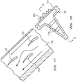
- heat transfer may be further augmented by inner features 150 ( FIG. 10 and 11 ) within each of the multiple of passages 120.
- inner features may be configured by control of fin density, thickness, and type can to balance stress with respect to the thermal loads.
- the inner features 150 are airfoil shapes that are staggered to further mix the oil for the purpose of enhancing convective heat transfer.
- the inner features 150 may include, for example, box, honeycomb, triangular, or other load bearing type structures, while for maximum thermal capabilities, the inner features 150 may include, for example, thin surfaces that provide significant surface area as well as combinations thereof.
- heat transfer isolation features 160 can be added on an internal surface 170 of the core cowl assembly 70 between multiple of passages 120 and the engine 20.
- the heat transfer isolation features 160 may, for example, insulate the system from the radiant heat load generated from the engine 20 to facilitate reduced heat input to the heat exchanger 82 to reduce the radiated heat input to the oil form the core, and maximize the heat out or cooling to the bypass flow).
- Examples of heat isolation features include thermal insulation blankets, thermal barrier coatings and reflective coatings with may be used individually or in combination.
- the thermal management system 80 provides for a greater cooling surface area compared to individual conventional heat exchangers by utilizing the circumference of the core cowl assembly 70 and the interface with the bypass flow.
- the surface area provides increased time for cooling as engine oil traverses the circuit from entrance to exit as well as avoids ducting and other associated structures.
- the external surface of the core cowl assembly 70 may also be configured to provide acoustic attenuation and a more uniform bypass flow resulting from elimination of unique discrete heat exchanger ducting and mixing of streams with differing momentum.
- the use of fins 100 and 100A may provide increased core cowl surface area combined with angular features which may be leveraged for the benefit of modified acoustic attenuation.
- acoustic treatment using coatings, perforated acoustic liners, local resonator features, etc. may be integrated into the cooling fins in manners which prevent interaction with internal oil coolant flow.
- Use of additive manufacturing allows local tailoring improved structural strength, increased wetted area, enhanced cooling effectiveness and weight reduction.
Landscapes
- Engineering & Computer Science (AREA)
- Mechanical Engineering (AREA)
- General Engineering & Computer Science (AREA)
- Chemical & Material Sciences (AREA)
- Aviation & Aerospace Engineering (AREA)
- Manufacturing & Machinery (AREA)
- Combustion & Propulsion (AREA)
- Materials Engineering (AREA)
- Physics & Mathematics (AREA)
- Thermal Sciences (AREA)
- Structures Of Non-Positive Displacement Pumps (AREA)
Applications Claiming Priority (1)
| Application Number | Priority Date | Filing Date | Title |
|---|---|---|---|
| US16/207,799 US11519295B2 (en) | 2018-12-03 | 2018-12-03 | Thermal management system for gas turbine engine |
Publications (2)
| Publication Number | Publication Date |
|---|---|
| EP3663541A1 true EP3663541A1 (de) | 2020-06-10 |
| EP3663541B1 EP3663541B1 (de) | 2023-09-20 |
Family
ID=68762476
Family Applications (1)
| Application Number | Title | Priority Date | Filing Date |
|---|---|---|---|
| EP19212696.9A Active EP3663541B1 (de) | 2018-12-03 | 2019-11-29 | Wärmeverwaltungssysteme für gasturbinentriebwerk |
Country Status (2)
| Country | Link |
|---|---|
| US (2) | US11519295B2 (de) |
| EP (1) | EP3663541B1 (de) |
Families Citing this family (5)
| Publication number | Priority date | Publication date | Assignee | Title |
|---|---|---|---|---|
| US10907500B2 (en) * | 2015-02-06 | 2021-02-02 | Raytheon Technologies Corporation | Heat exchanger system with spatially varied additively manufactured heat transfer surfaces |
| US11519295B2 (en) * | 2018-12-03 | 2022-12-06 | Raytheon Technologies Corporation | Thermal management system for gas turbine engine |
| DE102022114214A1 (de) | 2022-06-06 | 2023-12-07 | MTU Aero Engines AG | Antriebssystem für ein Luftfahrzeug |
| US12098649B2 (en) * | 2022-10-25 | 2024-09-24 | General Electric Company | Gas turbine engine accessory packaging |
| US20250236408A1 (en) * | 2024-01-22 | 2025-07-24 | Rtx Corporation | Framed heat exchanger for aircraft propulsion system |
Citations (8)
| Publication number | Priority date | Publication date | Assignee | Title |
|---|---|---|---|---|
| EP1985537A2 (de) * | 2007-04-23 | 2008-10-29 | United Technologies Corporation | Haubenanordnung in einem Triebwerkgondel |
| WO2012037988A1 (en) * | 2010-09-24 | 2012-03-29 | Short Brothers Plc | Nacelle with hinged cowl doors enabling access to the engine |
| EP2894323A1 (de) * | 2014-01-13 | 2015-07-15 | United Technologies Corporation | Luftumlenker mit doppelfunktion und fandüse mit variablem querschnitt |
| EP3012436A1 (de) * | 2014-10-21 | 2016-04-27 | United Technologies Corporation | Per additivfertigung hergestelltes kanalgeführtes wärmetauschersystem |
| US20170370246A1 (en) * | 2016-06-28 | 2017-12-28 | Pratt & Whitney Canada Corp. | Method for forming a composite part of a gas turbine engine |
| WO2018015659A1 (fr) * | 2016-07-20 | 2018-01-25 | Safran Nacelles | Nacelle de turbomoteur comportant un dispositif de refroidissement |
| EP3413001A1 (de) * | 2017-06-06 | 2018-12-12 | Ge Avio S.r.l. | Generativ hergestellter wärmetauscher |
| EP3483413A1 (de) * | 2017-11-14 | 2019-05-15 | The Boeing Company | Schalldämpfende wärmetauscher und verfahren zur verwendung davon |
Family Cites Families (15)
| Publication number | Priority date | Publication date | Assignee | Title |
|---|---|---|---|---|
| US5269133A (en) * | 1991-06-18 | 1993-12-14 | General Electric Company | Heat exchanger for cooling a gas turbine |
| GB2389174B (en) * | 2002-05-01 | 2005-10-26 | Rolls Royce Plc | Cooling systems |
| US7373778B2 (en) * | 2004-08-26 | 2008-05-20 | General Electric Company | Combustor cooling with angled segmented surfaces |
| US7856824B2 (en) * | 2007-06-25 | 2010-12-28 | Honeywell International Inc. | Cooling systems for use on aircraft |
| EP2075194B1 (de) | 2007-12-27 | 2017-08-16 | Techspace Aero | Luft-Öl-Wärmetauscher für ein Turbostrahltriebwerk, zugehöriges Turbostrahltriebwerk und Benutzung dieses Wärmetauschers |
| US9844807B2 (en) * | 2008-04-16 | 2017-12-19 | Wieland-Werke Ag | Tube with fins having wings |
| US9051943B2 (en) * | 2010-11-04 | 2015-06-09 | Hamilton Sundstrand Corporation | Gas turbine engine heat exchanger fins with periodic gaps |
| WO2012157521A1 (ja) * | 2011-05-17 | 2012-11-22 | シャープ株式会社 | 伝熱装置 |
| US9233757B2 (en) * | 2011-11-10 | 2016-01-12 | Rohr, Inc. | Nacelle |
| US9599410B2 (en) * | 2012-07-27 | 2017-03-21 | General Electric Company | Plate-like air-cooled engine surface cooler with fluid channel and varying fin geometry |
| FR3016956B1 (fr) * | 2014-01-29 | 2019-04-19 | Safran Aircraft Engines | Echangeur de chaleur d'une turbomachine |
| US10914185B2 (en) * | 2016-12-02 | 2021-02-09 | General Electric Company | Additive manufactured case with internal passages for active clearance control |
| GB201807202D0 (en) * | 2018-05-02 | 2018-06-13 | Rolls Royce Plc | Oil tank filling system |
| US11519295B2 (en) * | 2018-12-03 | 2022-12-06 | Raytheon Technologies Corporation | Thermal management system for gas turbine engine |
| US20200173365A1 (en) * | 2018-12-03 | 2020-06-04 | United Technologies Corporation | Thermal management system for low bypass gas turbine engine |
-
2018
- 2018-12-03 US US16/207,799 patent/US11519295B2/en active Active
-
2019
- 2019-11-29 EP EP19212696.9A patent/EP3663541B1/de active Active
-
2022
- 2022-11-02 US US17/979,393 patent/US11958623B2/en active Active
Patent Citations (8)
| Publication number | Priority date | Publication date | Assignee | Title |
|---|---|---|---|---|
| EP1985537A2 (de) * | 2007-04-23 | 2008-10-29 | United Technologies Corporation | Haubenanordnung in einem Triebwerkgondel |
| WO2012037988A1 (en) * | 2010-09-24 | 2012-03-29 | Short Brothers Plc | Nacelle with hinged cowl doors enabling access to the engine |
| EP2894323A1 (de) * | 2014-01-13 | 2015-07-15 | United Technologies Corporation | Luftumlenker mit doppelfunktion und fandüse mit variablem querschnitt |
| EP3012436A1 (de) * | 2014-10-21 | 2016-04-27 | United Technologies Corporation | Per additivfertigung hergestelltes kanalgeführtes wärmetauschersystem |
| US20170370246A1 (en) * | 2016-06-28 | 2017-12-28 | Pratt & Whitney Canada Corp. | Method for forming a composite part of a gas turbine engine |
| WO2018015659A1 (fr) * | 2016-07-20 | 2018-01-25 | Safran Nacelles | Nacelle de turbomoteur comportant un dispositif de refroidissement |
| EP3413001A1 (de) * | 2017-06-06 | 2018-12-12 | Ge Avio S.r.l. | Generativ hergestellter wärmetauscher |
| EP3483413A1 (de) * | 2017-11-14 | 2019-05-15 | The Boeing Company | Schalldämpfende wärmetauscher und verfahren zur verwendung davon |
Also Published As
| Publication number | Publication date |
|---|---|
| US20200173307A1 (en) | 2020-06-04 |
| EP3663541B1 (de) | 2023-09-20 |
| US11519295B2 (en) | 2022-12-06 |
| US20230058015A1 (en) | 2023-02-23 |
| US11958623B2 (en) | 2024-04-16 |
Similar Documents
| Publication | Publication Date | Title |
|---|---|---|
| US11684974B2 (en) | Additive manufactured ducted heat exchanger system | |
| US11958623B2 (en) | Thermal management system for gas turbine engine | |
| EP3012443B1 (de) | Wärmetauschersystem mit additiv hergestellter verkleidung | |
| US10753455B2 (en) | Additively manufactured gearbox with integral heat exchanger | |
| EP3054256B1 (de) | Additiv gefertigtes rohrwärmetauschersystem mit additiv gefertigter verkleidung | |
| EP3054254B1 (de) | Wärmetauschersystem mit räumlich veränderlichen, additiv gefertigten wärmeübertragungsflächen | |
| EP3054252B1 (de) | Wärmetauschersystem mit additiv gefertigtem wärmeübertragungsrohr, das einem nichtlinearen pfad folgt | |
| US10782071B2 (en) | Tubular array heat exchanger | |
| EP3663562B1 (de) | Wärmeverwaltungssystem für gasturbinenmotor mit geringem bypass | |
| US20180283795A1 (en) | Tubular Array Heat Exchanger | |
| US20200182069A1 (en) | Axial flow cooling scheme with castable structural rib for a gas turbine engine | |
| EP3663524A1 (de) | Axialflusskühlschema mit struktureller rippe für ein gasturbinentriebwerk |
Legal Events
| Date | Code | Title | Description |
|---|---|---|---|
| PUAI | Public reference made under article 153(3) epc to a published international application that has entered the european phase |
Free format text: ORIGINAL CODE: 0009012 |
|
| STAA | Information on the status of an ep patent application or granted ep patent |
Free format text: STATUS: THE APPLICATION HAS BEEN PUBLISHED |
|
| AK | Designated contracting states |
Kind code of ref document: A1 Designated state(s): AL AT BE BG CH CY CZ DE DK EE ES FI FR GB GR HR HU IE IS IT LI LT LU LV MC MK MT NL NO PL PT RO RS SE SI SK SM TR |
|
| AX | Request for extension of the european patent |
Extension state: BA ME |
|
| STAA | Information on the status of an ep patent application or granted ep patent |
Free format text: STATUS: REQUEST FOR EXAMINATION WAS MADE |
|
| 17P | Request for examination filed |
Effective date: 20201203 |
|
| RBV | Designated contracting states (corrected) |
Designated state(s): AL AT BE BG CH CY CZ DE DK EE ES FI FR GB GR HR HU IE IS IT LI LT LU LV MC MK MT NL NO PL PT RO RS SE SI SK SM TR |
|
| STAA | Information on the status of an ep patent application or granted ep patent |
Free format text: STATUS: EXAMINATION IS IN PROGRESS |
|
| RAP1 | Party data changed (applicant data changed or rights of an application transferred) |
Owner name: RAYTHEON TECHNOLOGIES CORPORATION |
|
| 17Q | First examination report despatched |
Effective date: 20210301 |
|
| RIC1 | Information provided on ipc code assigned before grant |
Ipc: F28F 13/12 20060101ALI20220404BHEP Ipc: F28D 21/00 20060101ALI20220404BHEP Ipc: B64D 29/08 20060101ALI20220404BHEP Ipc: F28D 1/06 20060101ALI20220404BHEP Ipc: B64D 29/00 20060101ALI20220404BHEP Ipc: B64D 33/08 20060101ALI20220404BHEP Ipc: B33Y 80/00 20150101ALI20220404BHEP Ipc: B22F 5/00 20060101ALI20220404BHEP Ipc: F01D 25/18 20060101ALI20220404BHEP Ipc: F01D 25/12 20060101AFI20220404BHEP |
|
| GRAP | Despatch of communication of intention to grant a patent |
Free format text: ORIGINAL CODE: EPIDOSNIGR1 |
|
| STAA | Information on the status of an ep patent application or granted ep patent |
Free format text: STATUS: GRANT OF PATENT IS INTENDED |
|
| INTG | Intention to grant announced |
Effective date: 20230330 |
|
| GRAS | Grant fee paid |
Free format text: ORIGINAL CODE: EPIDOSNIGR3 |
|
| GRAA | (expected) grant |
Free format text: ORIGINAL CODE: 0009210 |
|
| STAA | Information on the status of an ep patent application or granted ep patent |
Free format text: STATUS: THE PATENT HAS BEEN GRANTED |
|
| AK | Designated contracting states |
Kind code of ref document: B1 Designated state(s): AL AT BE BG CH CY CZ DE DK EE ES FI FR GB GR HR HU IE IS IT LI LT LU LV MC MK MT NL NO PL PT RO RS SE SI SK SM TR |
|
| REG | Reference to a national code |
Ref country code: GB Ref legal event code: FG4D |
|
| REG | Reference to a national code |
Ref country code: CH Ref legal event code: EP |
|
| REG | Reference to a national code |
Ref country code: DE Ref legal event code: R096 Ref document number: 602019037748 Country of ref document: DE |
|
| REG | Reference to a national code |
Ref country code: IE Ref legal event code: FG4D |
|
| RAP4 | Party data changed (patent owner data changed or rights of a patent transferred) |
Owner name: RTX CORPORATION |
|
| REG | Reference to a national code |
Ref country code: LT Ref legal event code: MG9D |
|
| PG25 | Lapsed in a contracting state [announced via postgrant information from national office to epo] |
Ref country code: GR Free format text: LAPSE BECAUSE OF FAILURE TO SUBMIT A TRANSLATION OF THE DESCRIPTION OR TO PAY THE FEE WITHIN THE PRESCRIBED TIME-LIMIT Effective date: 20231221 |
|
| REG | Reference to a national code |
Ref country code: NL Ref legal event code: MP Effective date: 20230920 |
|
| PG25 | Lapsed in a contracting state [announced via postgrant information from national office to epo] |
Ref country code: SE Free format text: LAPSE BECAUSE OF FAILURE TO SUBMIT A TRANSLATION OF THE DESCRIPTION OR TO PAY THE FEE WITHIN THE PRESCRIBED TIME-LIMIT Effective date: 20230920 Ref country code: RS Free format text: LAPSE BECAUSE OF FAILURE TO SUBMIT A TRANSLATION OF THE DESCRIPTION OR TO PAY THE FEE WITHIN THE PRESCRIBED TIME-LIMIT Effective date: 20230920 Ref country code: NO Free format text: LAPSE BECAUSE OF FAILURE TO SUBMIT A TRANSLATION OF THE DESCRIPTION OR TO PAY THE FEE WITHIN THE PRESCRIBED TIME-LIMIT Effective date: 20231220 Ref country code: LV Free format text: LAPSE BECAUSE OF FAILURE TO SUBMIT A TRANSLATION OF THE DESCRIPTION OR TO PAY THE FEE WITHIN THE PRESCRIBED TIME-LIMIT Effective date: 20230920 Ref country code: LT Free format text: LAPSE BECAUSE OF FAILURE TO SUBMIT A TRANSLATION OF THE DESCRIPTION OR TO PAY THE FEE WITHIN THE PRESCRIBED TIME-LIMIT Effective date: 20230920 Ref country code: HR Free format text: LAPSE BECAUSE OF FAILURE TO SUBMIT A TRANSLATION OF THE DESCRIPTION OR TO PAY THE FEE WITHIN THE PRESCRIBED TIME-LIMIT Effective date: 20230920 Ref country code: GR Free format text: LAPSE BECAUSE OF FAILURE TO SUBMIT A TRANSLATION OF THE DESCRIPTION OR TO PAY THE FEE WITHIN THE PRESCRIBED TIME-LIMIT Effective date: 20231221 Ref country code: FI Free format text: LAPSE BECAUSE OF FAILURE TO SUBMIT A TRANSLATION OF THE DESCRIPTION OR TO PAY THE FEE WITHIN THE PRESCRIBED TIME-LIMIT Effective date: 20230920 |
|
| REG | Reference to a national code |
Ref country code: AT Ref legal event code: MK05 Ref document number: 1613541 Country of ref document: AT Kind code of ref document: T Effective date: 20230920 |
|
| PG25 | Lapsed in a contracting state [announced via postgrant information from national office to epo] |
Ref country code: NL Free format text: LAPSE BECAUSE OF FAILURE TO SUBMIT A TRANSLATION OF THE DESCRIPTION OR TO PAY THE FEE WITHIN THE PRESCRIBED TIME-LIMIT Effective date: 20230920 |
|
| PG25 | Lapsed in a contracting state [announced via postgrant information from national office to epo] |
Ref country code: IS Free format text: LAPSE BECAUSE OF FAILURE TO SUBMIT A TRANSLATION OF THE DESCRIPTION OR TO PAY THE FEE WITHIN THE PRESCRIBED TIME-LIMIT Effective date: 20240120 |
|
| PG25 | Lapsed in a contracting state [announced via postgrant information from national office to epo] |
Ref country code: AT Free format text: LAPSE BECAUSE OF FAILURE TO SUBMIT A TRANSLATION OF THE DESCRIPTION OR TO PAY THE FEE WITHIN THE PRESCRIBED TIME-LIMIT Effective date: 20230920 |
|
| PG25 | Lapsed in a contracting state [announced via postgrant information from national office to epo] |
Ref country code: ES Free format text: LAPSE BECAUSE OF FAILURE TO SUBMIT A TRANSLATION OF THE DESCRIPTION OR TO PAY THE FEE WITHIN THE PRESCRIBED TIME-LIMIT Effective date: 20230920 |
|
| PG25 | Lapsed in a contracting state [announced via postgrant information from national office to epo] |
Ref country code: SM Free format text: LAPSE BECAUSE OF FAILURE TO SUBMIT A TRANSLATION OF THE DESCRIPTION OR TO PAY THE FEE WITHIN THE PRESCRIBED TIME-LIMIT Effective date: 20230920 Ref country code: RO Free format text: LAPSE BECAUSE OF FAILURE TO SUBMIT A TRANSLATION OF THE DESCRIPTION OR TO PAY THE FEE WITHIN THE PRESCRIBED TIME-LIMIT Effective date: 20230920 Ref country code: IS Free format text: LAPSE BECAUSE OF FAILURE TO SUBMIT A TRANSLATION OF THE DESCRIPTION OR TO PAY THE FEE WITHIN THE PRESCRIBED TIME-LIMIT Effective date: 20240120 Ref country code: ES Free format text: LAPSE BECAUSE OF FAILURE TO SUBMIT A TRANSLATION OF THE DESCRIPTION OR TO PAY THE FEE WITHIN THE PRESCRIBED TIME-LIMIT Effective date: 20230920 Ref country code: EE Free format text: LAPSE BECAUSE OF FAILURE TO SUBMIT A TRANSLATION OF THE DESCRIPTION OR TO PAY THE FEE WITHIN THE PRESCRIBED TIME-LIMIT Effective date: 20230920 Ref country code: CZ Free format text: LAPSE BECAUSE OF FAILURE TO SUBMIT A TRANSLATION OF THE DESCRIPTION OR TO PAY THE FEE WITHIN THE PRESCRIBED TIME-LIMIT Effective date: 20230920 Ref country code: AT Free format text: LAPSE BECAUSE OF FAILURE TO SUBMIT A TRANSLATION OF THE DESCRIPTION OR TO PAY THE FEE WITHIN THE PRESCRIBED TIME-LIMIT Effective date: 20230920 Ref country code: SK Free format text: LAPSE BECAUSE OF FAILURE TO SUBMIT A TRANSLATION OF THE DESCRIPTION OR TO PAY THE FEE WITHIN THE PRESCRIBED TIME-LIMIT Effective date: 20230920 Ref country code: PT Free format text: LAPSE BECAUSE OF FAILURE TO SUBMIT A TRANSLATION OF THE DESCRIPTION OR TO PAY THE FEE WITHIN THE PRESCRIBED TIME-LIMIT Effective date: 20240122 |
|
| PG25 | Lapsed in a contracting state [announced via postgrant information from national office to epo] |
Ref country code: PL Free format text: LAPSE BECAUSE OF FAILURE TO SUBMIT A TRANSLATION OF THE DESCRIPTION OR TO PAY THE FEE WITHIN THE PRESCRIBED TIME-LIMIT Effective date: 20230920 Ref country code: IT Free format text: LAPSE BECAUSE OF FAILURE TO SUBMIT A TRANSLATION OF THE DESCRIPTION OR TO PAY THE FEE WITHIN THE PRESCRIBED TIME-LIMIT Effective date: 20230920 |
|
| REG | Reference to a national code |
Ref country code: DE Ref legal event code: R097 Ref document number: 602019037748 Country of ref document: DE |
|
| REG | Reference to a national code |
Ref country code: CH Ref legal event code: PL |
|
| PG25 | Lapsed in a contracting state [announced via postgrant information from national office to epo] |
Ref country code: MC Free format text: LAPSE BECAUSE OF FAILURE TO SUBMIT A TRANSLATION OF THE DESCRIPTION OR TO PAY THE FEE WITHIN THE PRESCRIBED TIME-LIMIT Effective date: 20230920 |
|
| PG25 | Lapsed in a contracting state [announced via postgrant information from national office to epo] |
Ref country code: DK Free format text: LAPSE BECAUSE OF FAILURE TO SUBMIT A TRANSLATION OF THE DESCRIPTION OR TO PAY THE FEE WITHIN THE PRESCRIBED TIME-LIMIT Effective date: 20230920 |
|
| PG25 | Lapsed in a contracting state [announced via postgrant information from national office to epo] |
Ref country code: LU Free format text: LAPSE BECAUSE OF NON-PAYMENT OF DUE FEES Effective date: 20231129 |
|
| PG25 | Lapsed in a contracting state [announced via postgrant information from national office to epo] |
Ref country code: CH Free format text: LAPSE BECAUSE OF NON-PAYMENT OF DUE FEES Effective date: 20231130 |
|
| PLBE | No opposition filed within time limit |
Free format text: ORIGINAL CODE: 0009261 |
|
| STAA | Information on the status of an ep patent application or granted ep patent |
Free format text: STATUS: NO OPPOSITION FILED WITHIN TIME LIMIT |
|
| PG25 | Lapsed in a contracting state [announced via postgrant information from national office to epo] |
Ref country code: MC Free format text: LAPSE BECAUSE OF FAILURE TO SUBMIT A TRANSLATION OF THE DESCRIPTION OR TO PAY THE FEE WITHIN THE PRESCRIBED TIME-LIMIT Effective date: 20230920 Ref country code: LU Free format text: LAPSE BECAUSE OF NON-PAYMENT OF DUE FEES Effective date: 20231129 Ref country code: DK Free format text: LAPSE BECAUSE OF FAILURE TO SUBMIT A TRANSLATION OF THE DESCRIPTION OR TO PAY THE FEE WITHIN THE PRESCRIBED TIME-LIMIT Effective date: 20230920 Ref country code: CH Free format text: LAPSE BECAUSE OF NON-PAYMENT OF DUE FEES Effective date: 20231130 |
|
| REG | Reference to a national code |
Ref country code: BE Ref legal event code: MM Effective date: 20231130 |
|
| 26N | No opposition filed |
Effective date: 20240621 |
|
| REG | Reference to a national code |
Ref country code: IE Ref legal event code: MM4A |
|
| PG25 | Lapsed in a contracting state [announced via postgrant information from national office to epo] |
Ref country code: IE Free format text: LAPSE BECAUSE OF NON-PAYMENT OF DUE FEES Effective date: 20231129 |
|
| PG25 | Lapsed in a contracting state [announced via postgrant information from national office to epo] |
Ref country code: BE Free format text: LAPSE BECAUSE OF NON-PAYMENT OF DUE FEES Effective date: 20231130 |
|
| PG25 | Lapsed in a contracting state [announced via postgrant information from national office to epo] |
Ref country code: SI Free format text: LAPSE BECAUSE OF FAILURE TO SUBMIT A TRANSLATION OF THE DESCRIPTION OR TO PAY THE FEE WITHIN THE PRESCRIBED TIME-LIMIT Effective date: 20230920 |
|
| PG25 | Lapsed in a contracting state [announced via postgrant information from national office to epo] |
Ref country code: SI Free format text: LAPSE BECAUSE OF FAILURE TO SUBMIT A TRANSLATION OF THE DESCRIPTION OR TO PAY THE FEE WITHIN THE PRESCRIBED TIME-LIMIT Effective date: 20230920 Ref country code: IE Free format text: LAPSE BECAUSE OF NON-PAYMENT OF DUE FEES Effective date: 20231129 Ref country code: BE Free format text: LAPSE BECAUSE OF NON-PAYMENT OF DUE FEES Effective date: 20231130 |
|
| PG25 | Lapsed in a contracting state [announced via postgrant information from national office to epo] |
Ref country code: BG Free format text: LAPSE BECAUSE OF FAILURE TO SUBMIT A TRANSLATION OF THE DESCRIPTION OR TO PAY THE FEE WITHIN THE PRESCRIBED TIME-LIMIT Effective date: 20230920 |
|
| PG25 | Lapsed in a contracting state [announced via postgrant information from national office to epo] |
Ref country code: BG Free format text: LAPSE BECAUSE OF FAILURE TO SUBMIT A TRANSLATION OF THE DESCRIPTION OR TO PAY THE FEE WITHIN THE PRESCRIBED TIME-LIMIT Effective date: 20230920 |
|
| PG25 | Lapsed in a contracting state [announced via postgrant information from national office to epo] |
Ref country code: CY Free format text: LAPSE BECAUSE OF FAILURE TO SUBMIT A TRANSLATION OF THE DESCRIPTION OR TO PAY THE FEE WITHIN THE PRESCRIBED TIME-LIMIT; INVALID AB INITIO Effective date: 20191129 |
|
| PG25 | Lapsed in a contracting state [announced via postgrant information from national office to epo] |
Ref country code: HU Free format text: LAPSE BECAUSE OF FAILURE TO SUBMIT A TRANSLATION OF THE DESCRIPTION OR TO PAY THE FEE WITHIN THE PRESCRIBED TIME-LIMIT; INVALID AB INITIO Effective date: 20191129 |
|
| REG | Reference to a national code |
Ref country code: DE Ref legal event code: R081 Ref document number: 602019037748 Country of ref document: DE Owner name: RTX CORPORATION (N.D.GES.D. STAATES DELAWARE),, US Free format text: FORMER OWNER: RAYTHEON TECHNOLOGIES CORPORATION, FARMINGTON, CT, US |
|
| PG25 | Lapsed in a contracting state [announced via postgrant information from national office to epo] |
Ref country code: TR Free format text: LAPSE BECAUSE OF FAILURE TO SUBMIT A TRANSLATION OF THE DESCRIPTION OR TO PAY THE FEE WITHIN THE PRESCRIBED TIME-LIMIT Effective date: 20230920 |
|
| PGFP | Annual fee paid to national office [announced via postgrant information from national office to epo] |
Ref country code: DE Payment date: 20251022 Year of fee payment: 7 |
|
| PGFP | Annual fee paid to national office [announced via postgrant information from national office to epo] |
Ref country code: GB Payment date: 20251023 Year of fee payment: 7 |
|
| PGFP | Annual fee paid to national office [announced via postgrant information from national office to epo] |
Ref country code: FR Payment date: 20251022 Year of fee payment: 7 |
|
| P01 | Opt-out of the competence of the unified patent court (upc) registered |
Free format text: CASE NUMBER: UPC_APP_0018956_3663541/2025 Effective date: 20251222 |