EP3663543A1 - Gehäuseflansch mit spiralförmigen merkmalen - Google Patents
Gehäuseflansch mit spiralförmigen merkmalen Download PDFInfo
- Publication number
- EP3663543A1 EP3663543A1 EP19201795.2A EP19201795A EP3663543A1 EP 3663543 A1 EP3663543 A1 EP 3663543A1 EP 19201795 A EP19201795 A EP 19201795A EP 3663543 A1 EP3663543 A1 EP 3663543A1
- Authority
- EP
- European Patent Office
- Prior art keywords
- flange
- flange body
- fastener
- radial side
- scallop
- Prior art date
- Legal status (The legal status is an assumption and is not a legal conclusion. Google has not performed a legal analysis and makes no representation as to the accuracy of the status listed.)
- Granted
Links
Images


Classifications
-
- F—MECHANICAL ENGINEERING; LIGHTING; HEATING; WEAPONS; BLASTING
- F01—MACHINES OR ENGINES IN GENERAL; ENGINE PLANTS IN GENERAL; STEAM ENGINES
- F01D—NON-POSITIVE DISPLACEMENT MACHINES OR ENGINES, e.g. STEAM TURBINES
- F01D25/00—Component parts, details, or accessories, not provided for in, or of interest apart from, other groups
- F01D25/24—Casings; Casing parts, e.g. diaphragms, casing fastenings
- F01D25/243—Flange connections; Bolting arrangements
-
- F—MECHANICAL ENGINEERING; LIGHTING; HEATING; WEAPONS; BLASTING
- F01—MACHINES OR ENGINES IN GENERAL; ENGINE PLANTS IN GENERAL; STEAM ENGINES
- F01D—NON-POSITIVE DISPLACEMENT MACHINES OR ENGINES, e.g. STEAM TURBINES
- F01D25/00—Component parts, details, or accessories, not provided for in, or of interest apart from, other groups
- F01D25/28—Supporting or mounting arrangements, e.g. for turbine casing
-
- F—MECHANICAL ENGINEERING; LIGHTING; HEATING; WEAPONS; BLASTING
- F05—INDEXING SCHEMES RELATING TO ENGINES OR PUMPS IN VARIOUS SUBCLASSES OF CLASSES F01-F04
- F05D—INDEXING SCHEME FOR ASPECTS RELATING TO NON-POSITIVE-DISPLACEMENT MACHINES OR ENGINES, GAS-TURBINES OR JET-PROPULSION PLANTS
- F05D2220/00—Application
- F05D2220/30—Application in turbines
- F05D2220/32—Application in turbines in gas turbines
-
- F—MECHANICAL ENGINEERING; LIGHTING; HEATING; WEAPONS; BLASTING
- F05—INDEXING SCHEMES RELATING TO ENGINES OR PUMPS IN VARIOUS SUBCLASSES OF CLASSES F01-F04
- F05D—INDEXING SCHEME FOR ASPECTS RELATING TO NON-POSITIVE-DISPLACEMENT MACHINES OR ENGINES, GAS-TURBINES OR JET-PROPULSION PLANTS
- F05D2260/00—Function
- F05D2260/94—Functionality given by mechanical stress related aspects such as low cycle fatigue [LCF] of high cycle fatigue [HCF]
- F05D2260/941—Functionality given by mechanical stress related aspects such as low cycle fatigue [LCF] of high cycle fatigue [HCF] particularly aimed at mechanical or thermal stress reduction
-
- Y—GENERAL TAGGING OF NEW TECHNOLOGICAL DEVELOPMENTS; GENERAL TAGGING OF CROSS-SECTIONAL TECHNOLOGIES SPANNING OVER SEVERAL SECTIONS OF THE IPC; TECHNICAL SUBJECTS COVERED BY FORMER USPC CROSS-REFERENCE ART COLLECTIONS [XRACs] AND DIGESTS
- Y02—TECHNOLOGIES OR APPLICATIONS FOR MITIGATION OR ADAPTATION AGAINST CLIMATE CHANGE
- Y02T—CLIMATE CHANGE MITIGATION TECHNOLOGIES RELATED TO TRANSPORTATION
- Y02T50/00—Aeronautics or air transport
- Y02T50/60—Efficient propulsion technologies, e.g. for aircraft
Definitions
- This disclosure relates generally to aircraft gas turbine engine flanges, and more particularly to flange stress-reduction features.
- Flanges for gas turbine engines can be used to attach cases of various engine components, for example, an outer diffuser case and high-pressure turbine case. These flanges are often subject to external loads, large pressure variations, and thermal gradients, which may cause high levels of stress (e.g., hoop stress) in portions of the flange resulting in reduction of operational life. As a result, meeting product life requirements for these flanges may present a significant challenge.
- stress e.g., hoop stress
- a flange includes a flange body and a scallop feature.
- the flange body is annularly disposed about a longitudinal axis.
- the flange body includes a first radial side and a second radial side radially opposite the first radial side.
- the flange body defines a first fastener hole and a circumferentially adjacent second fastener hole. Each of the first fastener hole and the second fastener hole are formed through the flange body.
- the scallop feature is formed through the flange body and disposed circumferentially between the first and second fastener holes.
- the scallop feature extends radially from the first radial side through at least a portion of the flange body.
- the scallop feature includes a first side and a second side, parallel to the first side.
- the first and second sides have a radial orientation.
- a length of the first and second sides is greater than one-half of a radial length of the scallop feature.
- the scallop feature extends radially from the first radial side to a fastener diameter of at least one of the first and second fastener holes.
- the scallop feature extends circumferentially between a fastener diameter of each of the first and second fastener holes.
- the first radial side is a radially inward side of the flange.
- the first radial side is a radially outward side of the flange.
- the scallop feature is configured to reduce a stress of the flange body proximate an outer diameter of each of the first and second fastener holes.
- the stress is induced by at least one of a pressure differential and a thermal gradient across the flange body.
- the thermal gradient extends radially from an inner radial side of the flange body to an outer radial side of the flange body.
- a case includes a flange.
- the flange includes a flange body and at least one scallop feature.
- the flange body is annularly disposed about a longitudinal axis.
- the flange body includes a first radial side and a second radial side radially opposite the first radial side.
- the flange body defines a plurality of fastener holes.
- the plurality of fastener holes are formed through the flange body.
- Each scallop feature of the at least one scallop feature is formed through the flange body and disposed circumferentially between each pair of adjacent fastener holes of the plurality of fastener holes.
- the at least one scallop feature extends radially from the first radial side through at least a portion of the flange body.
- the at least one scallop feature includes a first side and a second side, parallel to the first side.
- the first and second sides have a radial orientation.
- a length of the first and second sides is greater than one-half of a radial length of each scallop feature of the at least one scallop feature.
- the at least one scallop feature extends radially from the first radial side to a fastener diameter of at least one of the first and second fastener holes.
- the at least one scallop feature extends circumferentially between a fastener diameter of each of the first and second fastener holes.
- a gas turbine engine includes a case and a flange in communication with the case.
- the flange includes a flange body and a scallop feature.
- the flange body is annularly disposed about a longitudinal axis.
- the flange body includes a first radial side and a second radial side radially opposite the first radial side.
- the flange body defines a first fastener hole and a circumferentially adjacent second fastener hole. Each of the first fastener hole and the second fastener hole are formed through the flange body.
- the scallop feature is formed through the flange body and disposed circumferentially between the first and second fastener holes.
- the scallop feature extends radially from the first radial side through at least a portion of the flange body.
- the scallop feature has a first side and a second side, parallel to the first side.
- the first and second sides have a radial orientation.
- a length of the first and second sides is greater than one-half of a radial length of the scallop feature.
- the scallop feature extends radially from the first radial side to a fastener diameter of at least one of the first and second fastener holes.
- the scallop feature extends circumferentially between a fastener diameter of each of the first and second fastener holes.
- connections are set forth between elements in the following description and in the drawings. It is noted that these connections are general and, unless specified otherwise, may be direct or indirect and that this specification is not intended to be limiting in this respect.
- a coupling between two or more entities may refer to a direct connection or an indirect connection.
- An indirect connection may incorporate one or more intervening entities.
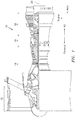
- FIG. 1 schematically illustrates a gas turbine engine 10.
- the gas turbine engine 10 generally includes a fan section 12, a compressor section 14, a combustor section 16, and a turbine section 18 disposed about a longitudinal axis 20 (e.g., a longitudinal centerline of the gas turbine engine 10).
- the fan section 12 drives air along a bypass flowpath while the compressor section 14 drives air along a core flowpath for compression and communication into the combustor section 16.
- the compressed air is heated by the combustor section 16 to generate a high-pressure exhaust gas stream that expands through the turbine section 18.
- the turbine section 18 extracts energy from the high-pressure exhaust gas stream to drive the fan section 12 and the compressor section 14.
- components of the gas turbine engine 10 including but not limited to the fan section 12, the compressor section 14, the combustor section 16, the turbine section 18, or parts of the preceding components can be assembled together with bolted flanges.
- component cases can include flanges to allow connection and assembly thereof.
- the flange 22 is used to assemble an outer diffuser case 26 with the high-pressure turbine case 28.
- the disclosed embodiments are not limited to flanges used for assembly of static cases and frames and may be applicable to other flanges, for example, rotor flanges.
- the flange 22 may be used to provide mating surfaces to connect a component case to another component.
- the flange 22 includes a first flange 22A and a second flange 22B.
- Flange fasteners 24 e.g., bolts
- FIG. 2 depicts a flanges 22A, 22B having an outer diameter fastening configuration (i.e., the flanges 22A, 22B are disposed radially outward of their respective cases).
- the disclosed embodiments may also be applicable for flanges having an inner diameter fastening configuration (i.e., the flanges are disposed radially inward of their respective cases).
- heat may be transferred from gas turbine engine 10 components (e.g., a combustor or high-pressure turbine) and component case to the flange 22 creating a thermal gradient across the flange 22.
- gas turbine engine 10 components e.g., a combustor or high-pressure turbine
- component case e.g., a combustor or high-pressure turbine
- the thermal gradient can create thermal stress in certain portions of the flange 22.
- the flange 22 generally includes a flange body 32 annularly disposed about the longitudinal axis 20 and having an inner radial side 34 and an outer radial side 36.
- a plurality of fastener holes 38 are formed through the flange body 32 (e.g., in an axial direction with respect to the longitudinal axis 20) and configured to receive the flange fasteners 24.
- Each fastener hole 38 includes an inner diameter 40 (i.e., the radially innermost portion of the fastener hole 38) and an outer diameter 42 (i.e., the radially outermost portion of the fastener hole 38).
- Each fastener hole 38 and corresponding flange fastener 24 also includes a fastener diameter 50 defined by a perimeter of a mounting face of the flange fastener 24 (i.e., the face of a head or nut of the flange fastener 24 abutting a face of the flange 22).
- the flange body 32 can have any suitable thickness and be formed from any suitable material.
- the flange body 32 is generally circular or hoop shaped.
- the plurality of fastener holes 38 and associated flange fasteners 24 may be used to provide a suitable coupling force needed for operation and assembly between associated flanges/cases (e.g., flanges 22A, 22B of FIG. 2 ).
- the fastener holes 38 may be disposed in a circumferential arrangement around the flange body 32.
- the flange 22 may be associated with, affixed to, or otherwise coupled to a case 100 (e.g., cases 26, 28 of FIG. 2 ).
- the flange 22 may be integrally formed with the case 100.
- the case 100 can be any suitable component case, including but not limited to, the outer diffuser case 26, the high-pressure turbine case 28, etc.
- the flange 22 may function as, for example, a bearing compartment flange or any other flange in a gas turbine engine 10.
- heat generating components such as components in the combustor section 16 or the turbine section 18, etc.
- the portion of the flange body 32 proximate the inner radial side 34 may heat up more than the portion of the flange body 32 proximate the outer radial side 36, creating a thermal gradient across the flange body 32.
- the thermal gradient extends in a generally radially outward direction (e.g., from the inner radial side 34 to the outer radial side 36), with hotter temperatures near the inner radial side 34 and cooler temperatures near the outer radial side 36.
- the thermal gradient can be affected by the ambient airflow proximate the outer radial side 36 of the flange 22.
- flange body 32 Due to thermal gradient experienced across the flange body 32, various portions of the flange body 32 can experience different temperatures at a given time. Various portions of the flange body 32 can expand at different rates in response to the difference in temperatures across the thermal gradient. As one of ordinary skill in the art will appreciate, if portions of the flange body 32 are constrained during thermal expansion and contraction, the flange body 32 can experience stress, including but not limited to, increased hoop (i.e., circumferential) stress. Stress across the flange body 32 may also be applied by other forces, for example, stress caused by a pressure differential across the flange body 32.
- the flange 22 includes at least one scallop feature 44 formed through the flange body 32 and disposed between circumferentially adjacent fastener holes of the plurality of fastener holes 38.
- the at least one scallop feature 44 is configured to reduce a stress of the flange body 32 caused by, for example, a thermal gradient, pressure differential, etc. across the flange body 32 by removing material from high hoop-stress areas.
- the at least one scallop feature 44 is further configured to reduce a stress of the flange body 32 without interfering with the cone of compression of the plurality of fastener holes 38 and associated flange fasteners 24.
- the at least one scallop feature 44 may reduce a stress of the flange body 32 proximate an outer diameter 42 of the each of the adjacent fastener holes of the plurality of fastener holes 38.
- the at least one scallop feature 44 extends radially from the outer radial side 36 through at least a portion of the flange body 32.
- the at least one scallop feature 44 may extend radially from the outer radial side 36 to a fastener diameter 50 of at least one of the circumferentially adjacent fastener holes of the plurality of fastener holes 38.
- the at least one scallop feature 44 may also extend circumferentially between the fastener diameters 50 of the circumferentially adjacent fastener holes of the plurality of fastener holes 38.
- the at least one scallop feature 44 is described herein as extending from the outer radial side 36 of the flange 22, in some embodiments the at least one scallop feature 44 may extend from the inner radial side 34 of the flange 22 (e.g., for a flange extending radially inward from a case).
- the at least one scallop feature 44 includes a first side 46 and a second side 48, parallel to the first side 46.
- the first side 46 and the second side 48 may be oriented generally radially.
- the first side 46 and the second side 48 have a length 52.
- the length 52 of the first and second sides 46, 48 may extend from the outer radial side 36 to the fastener diameter 50 of at least one of the circumferentially adjacent fastener holes of the plurality of fastener holes 38.
- the length 52 of the first and second sides 46, 48 may be a portion of a radial length 54 of the at least one scallop feature 44.
- the length 52 of the first and second sides 46, 48 may be greater than one-tenth, one-quarter, one-half, etc. of the radial length 54 of the at least one scallop feature 44.
- the first and second sides 46, 48 may have different lengths.
- the flange 22 includes an outer radial side 36 having a contoured shape (e.g., a generally rounded shape that is not parallel to the corresponding inner radial side 34) between adjacent scallop features of the at least one scallop feature 44.
- the contoured shape of the outer radial side 36 may provide a reduction of flange 22 weight as a result of reduced flange 22 material.
- the inner radial side 34 may have a contoured shape similar to that of the outer radial side 36 as illustrated in FIG. 4 , for example, where the at least one scallop feature 44 extends from the inner radial side 34.
Landscapes
- Engineering & Computer Science (AREA)
- Mechanical Engineering (AREA)
- General Engineering & Computer Science (AREA)
- Connection Of Plates (AREA)
Applications Claiming Priority (1)
| Application Number | Priority Date | Filing Date | Title |
|---|---|---|---|
| US16/213,128 US11421555B2 (en) | 2018-12-07 | 2018-12-07 | Case flange with scallop features |
Publications (2)
| Publication Number | Publication Date |
|---|---|
| EP3663543A1 true EP3663543A1 (de) | 2020-06-10 |
| EP3663543B1 EP3663543B1 (de) | 2023-11-29 |
Family
ID=68172142
Family Applications (1)
| Application Number | Title | Priority Date | Filing Date |
|---|---|---|---|
| EP19201795.2A Active EP3663543B1 (de) | 2018-12-07 | 2019-10-07 | Gehäuseflansch mit aussparungsmerkmalen |
Country Status (2)
| Country | Link |
|---|---|
| US (1) | US11421555B2 (de) |
| EP (1) | EP3663543B1 (de) |
Citations (3)
| Publication number | Priority date | Publication date | Assignee | Title |
|---|---|---|---|---|
| EP1091089A2 (de) * | 1999-09-07 | 2001-04-11 | General Electric Company | Kühlluftzufuhr durch die Verbindungsflansche eines Turbinenrotors |
| US20100316484A1 (en) * | 2009-06-15 | 2010-12-16 | General Electric Company | Mechanical joint for a gas turbine engine |
| US20160281541A1 (en) * | 2013-11-14 | 2016-09-29 | United Technologies Corporation | Flange relief for split casing |
Family Cites Families (17)
| Publication number | Priority date | Publication date | Assignee | Title |
|---|---|---|---|---|
| US3067983A (en) * | 1958-07-01 | 1962-12-11 | Gen Motors Corp | Turbine mounting construction |
| EP1288485B1 (de) * | 2001-08-31 | 2004-04-21 | Mann + Hummel GmbH | Saugrohr mit Befestigungsflansch und Einsatz zur Verstärkung des Flanschbauteils |
| US8388307B2 (en) * | 2009-07-21 | 2013-03-05 | Honeywell International Inc. | Turbine nozzle assembly including radially-compliant spring member for gas turbine engine |
| FR2983518B1 (fr) | 2011-12-06 | 2014-02-07 | Snecma | Dispositif deverrouillable d'arret axial d'une couronne d'etancheite contactee par une roue mobile de module de turbomachine d'aeronef |
| FR2986284B1 (fr) * | 2012-01-31 | 2014-03-28 | Snecma | Procede de reparation de marques d’usure. |
| US9410427B2 (en) * | 2012-06-05 | 2016-08-09 | United Technologies Corporation | Compressor power and torque transmitting hub |
| US9527173B2 (en) * | 2013-05-14 | 2016-12-27 | Siemens Energy, Inc. | Alignment tool for use in aligning openings in structural members |
| US9587519B2 (en) | 2013-11-22 | 2017-03-07 | Siemens Energy, Inc. | Modular industrial gas turbine exhaust system |
| GB201322048D0 (en) | 2013-12-13 | 2014-01-29 | Rolls Royce Deutschland | A joint between components |
| CA2944563C (en) * | 2014-04-11 | 2018-11-20 | General Electric Company | Turbine center frame fairing assembly |
| US9856753B2 (en) * | 2015-06-10 | 2018-01-02 | United Technologies Corporation | Inner diameter scallop case flange for a case of a gas turbine engine |
| DE102015223874A1 (de) * | 2015-12-01 | 2017-06-01 | Minimax Gmbh & Co. Kg | Verfahren zum Herstellen eines Flanschrohlings und eines Flansches |
| US10041534B2 (en) | 2016-02-08 | 2018-08-07 | General Electric Company | Bearing outer race retention during high load events |
| US10352238B2 (en) * | 2016-11-03 | 2019-07-16 | Rolls-Royce Corporation | Nose cone assembly without fasteners |
| US10507904B2 (en) * | 2016-11-03 | 2019-12-17 | Rolls-Royce Corporation | Snap fit nose cone assembly |
| US20180223691A1 (en) | 2017-02-03 | 2018-08-09 | United Technologies Corporation | Case flange with stress reducing features |
| US10941669B2 (en) * | 2018-12-21 | 2021-03-09 | Raytheon Technologies Corporation | Diffuser case support structure |
-
2018
- 2018-12-07 US US16/213,128 patent/US11421555B2/en active Active
-
2019
- 2019-10-07 EP EP19201795.2A patent/EP3663543B1/de active Active
Patent Citations (3)
| Publication number | Priority date | Publication date | Assignee | Title |
|---|---|---|---|---|
| EP1091089A2 (de) * | 1999-09-07 | 2001-04-11 | General Electric Company | Kühlluftzufuhr durch die Verbindungsflansche eines Turbinenrotors |
| US20100316484A1 (en) * | 2009-06-15 | 2010-12-16 | General Electric Company | Mechanical joint for a gas turbine engine |
| US20160281541A1 (en) * | 2013-11-14 | 2016-09-29 | United Technologies Corporation | Flange relief for split casing |
Also Published As
| Publication number | Publication date |
|---|---|
| US11421555B2 (en) | 2022-08-23 |
| US20200182091A1 (en) | 2020-06-11 |
| EP3663543B1 (de) | 2023-11-29 |
Similar Documents
| Publication | Publication Date | Title |
|---|---|---|
| US9874104B2 (en) | Method and system for a ceramic matrix composite shroud hanger assembly | |
| US11773751B1 (en) | Ceramic matrix composite blade track segment with pin-locating threaded insert | |
| US6612809B2 (en) | Thermally compliant discourager seal | |
| EP2690257A2 (de) | Befestigung | |
| US9771828B2 (en) | Turbine exhaust frame and method of vane assembly | |
| US9828867B2 (en) | Bumper for seals in a turbine exhaust case | |
| EP3546725A1 (de) | Inwendig gekühlte speiche | |
| US20160237854A1 (en) | Spacer for power turbine inlet heat shield | |
| US10718450B2 (en) | Flange joint assembly for use in a gas turbine engine | |
| US20160186614A1 (en) | Turbine exhaust case assembly | |
| US20160003081A1 (en) | Flexible finger seal for sealing a gap between turbine engine components | |
| US10928067B2 (en) | Double skin combustor | |
| US10036263B2 (en) | Stator assembly with pad interface for a gas turbine engine | |
| US9366185B2 (en) | Flexible connection between a wall and a case of a turbine engine | |
| EP3358154B1 (de) | Gehäuseflansches mit belastungsreduzierenden merkmalen | |
| US10316749B2 (en) | Conduit for guiding low pressure compressor inner diameter shroud motion | |
| EP3663543B1 (de) | Gehäuseflansch mit aussparungsmerkmalen | |
| US11428124B2 (en) | Flange stress-reduction features | |
| US11008880B2 (en) | Turbine section assembly with ceramic matrix composite vane | |
| US20250341192A1 (en) | Assembly for a turbine engine | |
| US10941669B2 (en) | Diffuser case support structure | |
| US11174754B1 (en) | Thermal bridge for connecting sections with a large temperature differential under high-pressure conditions | |
| US20200362762A1 (en) | Diffuser case support structure |
Legal Events
| Date | Code | Title | Description |
|---|---|---|---|
| PUAI | Public reference made under article 153(3) epc to a published international application that has entered the european phase |
Free format text: ORIGINAL CODE: 0009012 |
|
| STAA | Information on the status of an ep patent application or granted ep patent |
Free format text: STATUS: THE APPLICATION HAS BEEN PUBLISHED |
|
| AK | Designated contracting states |
Kind code of ref document: A1 Designated state(s): AL AT BE BG CH CY CZ DE DK EE ES FI FR GB GR HR HU IE IS IT LI LT LU LV MC MK MT NL NO PL PT RO RS SE SI SK SM TR |
|
| AX | Request for extension of the european patent |
Extension state: BA ME |
|
| STAA | Information on the status of an ep patent application or granted ep patent |
Free format text: STATUS: REQUEST FOR EXAMINATION WAS MADE |
|
| 17P | Request for examination filed |
Effective date: 20201210 |
|
| RBV | Designated contracting states (corrected) |
Designated state(s): AL AT BE BG CH CY CZ DE DK EE ES FI FR GB GR HR HU IE IS IT LI LT LU LV MC MK MT NL NO PL PT RO RS SE SI SK SM TR |
|
| RAP1 | Party data changed (applicant data changed or rights of an application transferred) |
Owner name: RAYTHEON TECHNOLOGIES CORPORATION |
|
| STAA | Information on the status of an ep patent application or granted ep patent |
Free format text: STATUS: EXAMINATION IS IN PROGRESS |
|
| 17Q | First examination report despatched |
Effective date: 20210610 |
|
| GRAP | Despatch of communication of intention to grant a patent |
Free format text: ORIGINAL CODE: EPIDOSNIGR1 |
|
| STAA | Information on the status of an ep patent application or granted ep patent |
Free format text: STATUS: GRANT OF PATENT IS INTENDED |
|
| INTG | Intention to grant announced |
Effective date: 20221212 |
|
| GRAJ | Information related to disapproval of communication of intention to grant by the applicant or resumption of examination proceedings by the epo deleted |
Free format text: ORIGINAL CODE: EPIDOSDIGR1 |
|
| STAA | Information on the status of an ep patent application or granted ep patent |
Free format text: STATUS: EXAMINATION IS IN PROGRESS |
|
| GRAP | Despatch of communication of intention to grant a patent |
Free format text: ORIGINAL CODE: EPIDOSNIGR1 |
|
| STAA | Information on the status of an ep patent application or granted ep patent |
Free format text: STATUS: GRANT OF PATENT IS INTENDED |
|
| INTC | Intention to grant announced (deleted) | ||
| INTG | Intention to grant announced |
Effective date: 20230515 |
|
| GRAS | Grant fee paid |
Free format text: ORIGINAL CODE: EPIDOSNIGR3 |
|
| GRAA | (expected) grant |
Free format text: ORIGINAL CODE: 0009210 |
|
| STAA | Information on the status of an ep patent application or granted ep patent |
Free format text: STATUS: THE PATENT HAS BEEN GRANTED |
|
| RAP3 | Party data changed (applicant data changed or rights of an application transferred) |
Owner name: RTX CORPORATION |
|
| AK | Designated contracting states |
Kind code of ref document: B1 Designated state(s): AL AT BE BG CH CY CZ DE DK EE ES FI FR GB GR HR HU IE IS IT LI LT LU LV MC MK MT NL NO PL PT RO RS SE SI SK SM TR |
|
| REG | Reference to a national code |
Ref country code: GB Ref legal event code: FG4D |
|
| REG | Reference to a national code |
Ref country code: CH Ref legal event code: EP |
|
| REG | Reference to a national code |
Ref country code: DE Ref legal event code: R096 Ref document number: 602019042248 Country of ref document: DE |
|
| REG | Reference to a national code |
Ref country code: IE Ref legal event code: FG4D |
|
| REG | Reference to a national code |
Ref country code: LT Ref legal event code: MG9D |
|
| REG | Reference to a national code |
Ref country code: NL Ref legal event code: MP Effective date: 20231129 |
|
| PG25 | Lapsed in a contracting state [announced via postgrant information from national office to epo] |
Ref country code: GR Free format text: LAPSE BECAUSE OF FAILURE TO SUBMIT A TRANSLATION OF THE DESCRIPTION OR TO PAY THE FEE WITHIN THE PRESCRIBED TIME-LIMIT Effective date: 20240301 |
|
| PG25 | Lapsed in a contracting state [announced via postgrant information from national office to epo] |
Ref country code: IS Free format text: LAPSE BECAUSE OF FAILURE TO SUBMIT A TRANSLATION OF THE DESCRIPTION OR TO PAY THE FEE WITHIN THE PRESCRIBED TIME-LIMIT Effective date: 20240329 |
|
| PG25 | Lapsed in a contracting state [announced via postgrant information from national office to epo] |
Ref country code: LT Free format text: LAPSE BECAUSE OF FAILURE TO SUBMIT A TRANSLATION OF THE DESCRIPTION OR TO PAY THE FEE WITHIN THE PRESCRIBED TIME-LIMIT Effective date: 20231129 |
|
| PG25 | Lapsed in a contracting state [announced via postgrant information from national office to epo] |
Ref country code: ES Free format text: LAPSE BECAUSE OF FAILURE TO SUBMIT A TRANSLATION OF THE DESCRIPTION OR TO PAY THE FEE WITHIN THE PRESCRIBED TIME-LIMIT Effective date: 20231129 |
|
| PG25 | Lapsed in a contracting state [announced via postgrant information from national office to epo] |
Ref country code: LT Free format text: LAPSE BECAUSE OF FAILURE TO SUBMIT A TRANSLATION OF THE DESCRIPTION OR TO PAY THE FEE WITHIN THE PRESCRIBED TIME-LIMIT Effective date: 20231129 Ref country code: IS Free format text: LAPSE BECAUSE OF FAILURE TO SUBMIT A TRANSLATION OF THE DESCRIPTION OR TO PAY THE FEE WITHIN THE PRESCRIBED TIME-LIMIT Effective date: 20240329 Ref country code: GR Free format text: LAPSE BECAUSE OF FAILURE TO SUBMIT A TRANSLATION OF THE DESCRIPTION OR TO PAY THE FEE WITHIN THE PRESCRIBED TIME-LIMIT Effective date: 20240301 Ref country code: ES Free format text: LAPSE BECAUSE OF FAILURE TO SUBMIT A TRANSLATION OF THE DESCRIPTION OR TO PAY THE FEE WITHIN THE PRESCRIBED TIME-LIMIT Effective date: 20231129 Ref country code: BG Free format text: LAPSE BECAUSE OF FAILURE TO SUBMIT A TRANSLATION OF THE DESCRIPTION OR TO PAY THE FEE WITHIN THE PRESCRIBED TIME-LIMIT Effective date: 20240229 |
|
| REG | Reference to a national code |
Ref country code: AT Ref legal event code: MK05 Ref document number: 1636324 Country of ref document: AT Kind code of ref document: T Effective date: 20231129 |
|
| PG25 | Lapsed in a contracting state [announced via postgrant information from national office to epo] |
Ref country code: NL Free format text: LAPSE BECAUSE OF FAILURE TO SUBMIT A TRANSLATION OF THE DESCRIPTION OR TO PAY THE FEE WITHIN THE PRESCRIBED TIME-LIMIT Effective date: 20231129 |
|
| PG25 | Lapsed in a contracting state [announced via postgrant information from national office to epo] |
Ref country code: SE Free format text: LAPSE BECAUSE OF FAILURE TO SUBMIT A TRANSLATION OF THE DESCRIPTION OR TO PAY THE FEE WITHIN THE PRESCRIBED TIME-LIMIT Effective date: 20231129 Ref country code: RS Free format text: LAPSE BECAUSE OF FAILURE TO SUBMIT A TRANSLATION OF THE DESCRIPTION OR TO PAY THE FEE WITHIN THE PRESCRIBED TIME-LIMIT Effective date: 20231129 Ref country code: PL Free format text: LAPSE BECAUSE OF FAILURE TO SUBMIT A TRANSLATION OF THE DESCRIPTION OR TO PAY THE FEE WITHIN THE PRESCRIBED TIME-LIMIT Effective date: 20231129 Ref country code: NO Free format text: LAPSE BECAUSE OF FAILURE TO SUBMIT A TRANSLATION OF THE DESCRIPTION OR TO PAY THE FEE WITHIN THE PRESCRIBED TIME-LIMIT Effective date: 20240229 Ref country code: NL Free format text: LAPSE BECAUSE OF FAILURE TO SUBMIT A TRANSLATION OF THE DESCRIPTION OR TO PAY THE FEE WITHIN THE PRESCRIBED TIME-LIMIT Effective date: 20231129 Ref country code: LV Free format text: LAPSE BECAUSE OF FAILURE TO SUBMIT A TRANSLATION OF THE DESCRIPTION OR TO PAY THE FEE WITHIN THE PRESCRIBED TIME-LIMIT Effective date: 20231129 Ref country code: HR Free format text: LAPSE BECAUSE OF FAILURE TO SUBMIT A TRANSLATION OF THE DESCRIPTION OR TO PAY THE FEE WITHIN THE PRESCRIBED TIME-LIMIT Effective date: 20231129 |
|
| PG25 | Lapsed in a contracting state [announced via postgrant information from national office to epo] |
Ref country code: DK Free format text: LAPSE BECAUSE OF FAILURE TO SUBMIT A TRANSLATION OF THE DESCRIPTION OR TO PAY THE FEE WITHIN THE PRESCRIBED TIME-LIMIT Effective date: 20231129 |
|
| PG25 | Lapsed in a contracting state [announced via postgrant information from national office to epo] |
Ref country code: AT Free format text: LAPSE BECAUSE OF FAILURE TO SUBMIT A TRANSLATION OF THE DESCRIPTION OR TO PAY THE FEE WITHIN THE PRESCRIBED TIME-LIMIT Effective date: 20231129 Ref country code: CZ Free format text: LAPSE BECAUSE OF FAILURE TO SUBMIT A TRANSLATION OF THE DESCRIPTION OR TO PAY THE FEE WITHIN THE PRESCRIBED TIME-LIMIT Effective date: 20231129 |
|
| PG25 | Lapsed in a contracting state [announced via postgrant information from national office to epo] |
Ref country code: SK Free format text: LAPSE BECAUSE OF FAILURE TO SUBMIT A TRANSLATION OF THE DESCRIPTION OR TO PAY THE FEE WITHIN THE PRESCRIBED TIME-LIMIT Effective date: 20231129 |
|
| PG25 | Lapsed in a contracting state [announced via postgrant information from national office to epo] |
Ref country code: SM Free format text: LAPSE BECAUSE OF FAILURE TO SUBMIT A TRANSLATION OF THE DESCRIPTION OR TO PAY THE FEE WITHIN THE PRESCRIBED TIME-LIMIT Effective date: 20231129 Ref country code: SK Free format text: LAPSE BECAUSE OF FAILURE TO SUBMIT A TRANSLATION OF THE DESCRIPTION OR TO PAY THE FEE WITHIN THE PRESCRIBED TIME-LIMIT Effective date: 20231129 Ref country code: RO Free format text: LAPSE BECAUSE OF FAILURE TO SUBMIT A TRANSLATION OF THE DESCRIPTION OR TO PAY THE FEE WITHIN THE PRESCRIBED TIME-LIMIT Effective date: 20231129 Ref country code: IT Free format text: LAPSE BECAUSE OF FAILURE TO SUBMIT A TRANSLATION OF THE DESCRIPTION OR TO PAY THE FEE WITHIN THE PRESCRIBED TIME-LIMIT Effective date: 20231129 Ref country code: EE Free format text: LAPSE BECAUSE OF FAILURE TO SUBMIT A TRANSLATION OF THE DESCRIPTION OR TO PAY THE FEE WITHIN THE PRESCRIBED TIME-LIMIT Effective date: 20231129 Ref country code: DK Free format text: LAPSE BECAUSE OF FAILURE TO SUBMIT A TRANSLATION OF THE DESCRIPTION OR TO PAY THE FEE WITHIN THE PRESCRIBED TIME-LIMIT Effective date: 20231129 Ref country code: CZ Free format text: LAPSE BECAUSE OF FAILURE TO SUBMIT A TRANSLATION OF THE DESCRIPTION OR TO PAY THE FEE WITHIN THE PRESCRIBED TIME-LIMIT Effective date: 20231129 Ref country code: AT Free format text: LAPSE BECAUSE OF FAILURE TO SUBMIT A TRANSLATION OF THE DESCRIPTION OR TO PAY THE FEE WITHIN THE PRESCRIBED TIME-LIMIT Effective date: 20231129 |
|
| PG25 | Lapsed in a contracting state [announced via postgrant information from national office to epo] |
Ref country code: PT Free format text: LAPSE BECAUSE OF FAILURE TO SUBMIT A TRANSLATION OF THE DESCRIPTION OR TO PAY THE FEE WITHIN THE PRESCRIBED TIME-LIMIT Effective date: 20240401 |
|
| PG25 | Lapsed in a contracting state [announced via postgrant information from national office to epo] |
Ref country code: PT Free format text: LAPSE BECAUSE OF FAILURE TO SUBMIT A TRANSLATION OF THE DESCRIPTION OR TO PAY THE FEE WITHIN THE PRESCRIBED TIME-LIMIT Effective date: 20240401 |
|
| REG | Reference to a national code |
Ref country code: DE Ref legal event code: R097 Ref document number: 602019042248 Country of ref document: DE |
|
| PLBE | No opposition filed within time limit |
Free format text: ORIGINAL CODE: 0009261 |
|
| STAA | Information on the status of an ep patent application or granted ep patent |
Free format text: STATUS: NO OPPOSITION FILED WITHIN TIME LIMIT |
|
| PG25 | Lapsed in a contracting state [announced via postgrant information from national office to epo] |
Ref country code: SI Free format text: LAPSE BECAUSE OF FAILURE TO SUBMIT A TRANSLATION OF THE DESCRIPTION OR TO PAY THE FEE WITHIN THE PRESCRIBED TIME-LIMIT Effective date: 20231129 |
|
| PG25 | Lapsed in a contracting state [announced via postgrant information from national office to epo] |
Ref country code: SI Free format text: LAPSE BECAUSE OF FAILURE TO SUBMIT A TRANSLATION OF THE DESCRIPTION OR TO PAY THE FEE WITHIN THE PRESCRIBED TIME-LIMIT Effective date: 20231129 |
|
| 26N | No opposition filed |
Effective date: 20240830 |
|
| REG | Reference to a national code |
Ref country code: CH Ref legal event code: PL |
|
| PG25 | Lapsed in a contracting state [announced via postgrant information from national office to epo] |
Ref country code: MC Free format text: LAPSE BECAUSE OF FAILURE TO SUBMIT A TRANSLATION OF THE DESCRIPTION OR TO PAY THE FEE WITHIN THE PRESCRIBED TIME-LIMIT Effective date: 20231129 |
|
| PG25 | Lapsed in a contracting state [announced via postgrant information from national office to epo] |
Ref country code: LU Free format text: LAPSE BECAUSE OF NON-PAYMENT OF DUE FEES Effective date: 20241007 Ref country code: BE Free format text: LAPSE BECAUSE OF NON-PAYMENT OF DUE FEES Effective date: 20241031 |
|
| PG25 | Lapsed in a contracting state [announced via postgrant information from national office to epo] |
Ref country code: CH Free format text: LAPSE BECAUSE OF NON-PAYMENT OF DUE FEES Effective date: 20241031 |
|
| REG | Reference to a national code |
Ref country code: BE Ref legal event code: MM Effective date: 20241031 |
|
| PG25 | Lapsed in a contracting state [announced via postgrant information from national office to epo] |
Ref country code: FI Free format text: LAPSE BECAUSE OF FAILURE TO SUBMIT A TRANSLATION OF THE DESCRIPTION OR TO PAY THE FEE WITHIN THE PRESCRIBED TIME-LIMIT Effective date: 20231129 |
|
| PGFP | Annual fee paid to national office [announced via postgrant information from national office to epo] |
Ref country code: GB Payment date: 20250923 Year of fee payment: 7 |
|
| PGFP | Annual fee paid to national office [announced via postgrant information from national office to epo] |
Ref country code: FR Payment date: 20250923 Year of fee payment: 7 |
|
| PG25 | Lapsed in a contracting state [announced via postgrant information from national office to epo] |
Ref country code: IE Free format text: LAPSE BECAUSE OF NON-PAYMENT OF DUE FEES Effective date: 20241007 |
|
| PGFP | Annual fee paid to national office [announced via postgrant information from national office to epo] |
Ref country code: DE Payment date: 20250923 Year of fee payment: 7 |
|
| P01 | Opt-out of the competence of the unified patent court (upc) registered |
Free format text: CASE NUMBER: UPC_APP_0019383_3663543/2025 Effective date: 20251223 |
|
| PG25 | Lapsed in a contracting state [announced via postgrant information from national office to epo] |
Ref country code: CY Free format text: LAPSE BECAUSE OF FAILURE TO SUBMIT A TRANSLATION OF THE DESCRIPTION OR TO PAY THE FEE WITHIN THE PRESCRIBED TIME-LIMIT; INVALID AB INITIO Effective date: 20191007 |
|
| PG25 | Lapsed in a contracting state [announced via postgrant information from national office to epo] |
Ref country code: HU Free format text: LAPSE BECAUSE OF FAILURE TO SUBMIT A TRANSLATION OF THE DESCRIPTION OR TO PAY THE FEE WITHIN THE PRESCRIBED TIME-LIMIT; INVALID AB INITIO Effective date: 20191007 |