EP3663548A1 - Dämpfer für eine brennkammeranordnung eines gasturbinenkraftwerks und brennkammeranordnung mit dem dämpfer - Google Patents
Dämpfer für eine brennkammeranordnung eines gasturbinenkraftwerks und brennkammeranordnung mit dem dämpfer Download PDFInfo
- Publication number
- EP3663548A1 EP3663548A1 EP18210858.9A EP18210858A EP3663548A1 EP 3663548 A1 EP3663548 A1 EP 3663548A1 EP 18210858 A EP18210858 A EP 18210858A EP 3663548 A1 EP3663548 A1 EP 3663548A1
- Authority
- EP
- European Patent Office
- Prior art keywords
- damper
- combustor assembly
- neck
- damper body
- damping
- Prior art date
- Legal status (The legal status is an assumption and is not a legal conclusion. Google has not performed a legal analysis and makes no representation as to the accuracy of the status listed.)
- Granted
Links
Images


Classifications
-
- F—MECHANICAL ENGINEERING; LIGHTING; HEATING; WEAPONS; BLASTING
- F01—MACHINES OR ENGINES IN GENERAL; ENGINE PLANTS IN GENERAL; STEAM ENGINES
- F01N—GAS-FLOW SILENCERS OR EXHAUST APPARATUS FOR MACHINES OR ENGINES IN GENERAL; GAS-FLOW SILENCERS OR EXHAUST APPARATUS FOR INTERNAL-COMBUSTION ENGINES
- F01N1/00—Silencing apparatus characterised by method of silencing
- F01N1/02—Silencing apparatus characterised by method of silencing by using resonance
- F01N1/023—Helmholtz resonators
-
- F—MECHANICAL ENGINEERING; LIGHTING; HEATING; WEAPONS; BLASTING
- F23—COMBUSTION APPARATUS; COMBUSTION PROCESSES
- F23R—GENERATING COMBUSTION PRODUCTS OF HIGH PRESSURE OR HIGH VELOCITY, e.g. GAS-TURBINE COMBUSTION CHAMBERS
- F23R3/00—Continuous combustion chambers using liquid or gaseous fuel
- F23R3/42—Continuous combustion chambers using liquid or gaseous fuel characterised by the arrangement or form of the flame tubes or combustion chambers
-
- F—MECHANICAL ENGINEERING; LIGHTING; HEATING; WEAPONS; BLASTING
- F23—COMBUSTION APPARATUS; COMBUSTION PROCESSES
- F23R—GENERATING COMBUSTION PRODUCTS OF HIGH PRESSURE OR HIGH VELOCITY, e.g. GAS-TURBINE COMBUSTION CHAMBERS
- F23R2900/00—Special features of, or arrangements for continuous combustion chambers; Combustion processes therefor
- F23R2900/00014—Reducing thermo-acoustic vibrations by passive means, e.g. by Helmholtz resonators
-
- F—MECHANICAL ENGINEERING; LIGHTING; HEATING; WEAPONS; BLASTING
- F23—COMBUSTION APPARATUS; COMBUSTION PROCESSES
- F23R—GENERATING COMBUSTION PRODUCTS OF HIGH PRESSURE OR HIGH VELOCITY, e.g. GAS-TURBINE COMBUSTION CHAMBERS
- F23R2900/00—Special features of, or arrangements for continuous combustion chambers; Combustion processes therefor
- F23R2900/03341—Sequential combustion chambers or burners
-
- F—MECHANICAL ENGINEERING; LIGHTING; HEATING; WEAPONS; BLASTING
- F23—COMBUSTION APPARATUS; COMBUSTION PROCESSES
- F23R—GENERATING COMBUSTION PRODUCTS OF HIGH PRESSURE OR HIGH VELOCITY, e.g. GAS-TURBINE COMBUSTION CHAMBERS
- F23R3/00—Continuous combustion chambers using liquid or gaseous fuel
- F23R3/28—Continuous combustion chambers using liquid or gaseous fuel characterised by the fuel supply
- F23R3/34—Feeding into different combustion zones
- F23R3/346—Feeding into different combustion zones for staged combustion
Definitions
- the present invention relates to a damper for a combustor assembly of a gas turbine and to a combustor assembly of a gas turbine comprising said damper.
- the present invention relates to a damper for a sequential combustor assembly.
- a gas turbine power plant comprises a compressor, a combustor assembly and a turbine.
- the compressor is supplied with air and comprises a plurality of blades compressing the supplied air.
- the compressed air leaving the compressor flows into a plenum, i.e. a closed volume delimited by an outer casing, and from there into the combustor assembly.
- a plenum i.e. a closed volume delimited by an outer casing
- the compressed air and at least one fuel are combusted.
- the resulting hot gas leaves the combustor assembly and is expanded in the turbine performing work.
- sequential combustor assemblies can be used.
- a sequential combustor assembly comprises two combustors in series: a first-stage combustor and a second-stage combustor, which is arranged downstream the first-stage combustor along the gas flow.
- a combustor assembly with a single combustion stage can be also used.
- Known dampers comprise one damper volume that acts as a resonator volume and a neck fluidly connecting the damper volume to at least one inner chamber of the combustor assembly.
- the object of the present invention is therefore to provide a damper for a combustor assembly, which is flexible, simple and economical, both from the functional and the constructive point of view.
- a damper for a combustor assembly of a gas turbine plant comprising a first damper body, which defines at least one first damping volume and comprises at least one opening; a neck coupled to the opening of the first damper body and configured for fluidly connecting the first damping volume with a combustion chamber of the combustor assembly; and a second damper body, which extends, at least in part, about at least a portion of the neck and defines at least one second damping volume; the second damper body comprising at least one opening fluidly connecting the second damping volume to the combustion chamber of the combustor assembly.
- the structure of the damper according to the invention is very compact and flexible.
- the flexibility is given by the possibility of damping different frequencies, as the damping volumes can be sized opportunely depending on the needs.
- the compact structure allows satisfying the strict dimensional constraints of the modern combustor assemblies. In modern combustor assemblies, in fact, the spaces available for traditional dampers installation are few and, additionally, these spaces are not always arranged where acoustic damping is really needed.
- the compact structure of the damper according to the present invention allows also the installation in positions closer to the zones where damping is really needed. Moreover, thanks to its compactness, the damper according to the present invention can be used for replacing most of the existing dampers.
- the second damper body is annular. In this way the structure of the damper is simple and easy to manufacture.
- the neck has a first end connected to the opening and a second end facing an area in fluid communication with the combustion chamber; the second damper body extending about the second end. In this way the second damper body is closer to the area in fluid communication with the combustion chamber.
- the second damper body comprises a plurality of openings fluidly connecting the second damping volume to the combustion chamber of the combustor assembly. In this way, the vortices created at the openings maximize acoustic energy absorption.
- the second damper body comprises a plurality of second damping volumes, each of which is fluidly connected to the combustion chamber of the combustor assembly by means of a respective plurality of openings.
- the second damper body has a more flexible structure as each second damping volume can be opportunely configured and sized so as to damp one or more frequency.
- the second damping volumes are evenly distributed in the second damper body. In this way the structure of the damper is simple and easy to manufacture.
- the second damping volumes are identical to each other. In this way the absorption is maximized in a given frequency band.
- the second damper body having an axial length, which is smaller than the axial length of the neck.
- the second damper body comprises at least one auxiliary opening fluidly connecting the second damping volume to a source of air.
- This air has two functions: cooling the damper surface (which is typically facing the flame), and avoiding hot gas ingestion (which would de-tune the second damper body and could cause damages to the second damping body itself).
- the first damper body and the neck are configured and dimensioned so as to damp at least one first frequency comprised in a first frequency band and the second damper body is configured and dimensioned so as to damp at least one second frequency comprised in a second frequency band; the first frequency and the second frequency are different from each other.
- the first frequency band is 50-1000 Hz and the second frequency band is 1000-10000 Hz.
- the first damper body and the neck are made as a single body.
- the first damper body, the neck and the second damper body are made as a single body.
- the present invention relates to a combustor assembly comprising at least one damper as described above.
- the combustor assembly extends along a longitudinal axis and comprises at least one center hollow body arranged along the longitudinal axis and a plurality of lobes extending radially from the center hollow body; the damper is arranged, at least in part, in the center hollow body.
- the integration of the damper into the central hollow body has several advantages: it is an ideal location to damp combustion dynamics as it is close to the flame and it is the best location to damp radial acoustic modes.
- reference numeral 1 indicates a gas turbine assembly.
- the gas turbine assembly 1 comprises a compressor 2, a sequential combustor assembly 3 and a turbine 5.
- the compressor 2 and the turbine 3 extend along a main axis A.
- an airflow compressed in the compressor 2 is mixed with fuel and is burned in the sequential combustor assembly 3.
- the burned mixture is then expanded in the turbine 5 and converted in mechanical power by a shaft 6, which is connected to an alternator (not shown).
- the sequential combustor assembly 3 comprises a first-stage combustor 8 and a second-stage combustor 9 sequentially arranged along the gas flow direction G.
- the second stage combustor 9 is arranged downstream the first stage combustor 8 along the gas flow direction G.
- a mixer 11 is arranged between the first stage combustor 8 and the second stage combustor 9 .
- the first stage combustor 8 defines a first combustion chamber 14, the second stage combustor 9 defines a second combustion chamber 16, while the mixer 11 defines a mixing chamber 17.
- the first combustion chamber 14, the second combustion chamber 16 and the mixing chamber 17 are in fluidic communication and are defined by a liner 18 (see figure 4 wherein it is partially visible), which extends along a longitudinal axis B, preferably parallel to the main axis A.
- a supply assembly 20 is arranged in the second combustion chamber 16 of the second stage combustor 9 .
- the supply assembly 20 comprises a central hollow body 21 and a plurality of lobes 22 (schematically represented in figure 4 ), each of which extends radially about the central hollow body 21.
- the central hollow body 21 can be called also "central nose”.
- the lobes 22 are preferably defined by streamlined bodies, each of which is provided with a plurality of nozzles 24 and is supplied with air and at least one fuel.
- connection 25 between an inner air channel 26 of at least one lobe 22 and an inner chamber 27 of the central hollow body 21 is realized in order to allow air entering in the inner chamber 27.
- the connection 25 is represented schematically.
- a damper 30 is arranged in the inner chamber 27 of the central hollow body 21 to damp the fluctuations inside the second stage combustor 9.
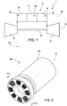
- damper 30 extends along an extension axis C and comprises a first damper body 31, a neck 33 and a second damper body 34 extending, at least in part, about the neck 33.
- the first damper body 31 defines at least one first damping volume 35 and comprises at least one opening 36 (only visible in figure 3 ) connected to the neck 33.
- the first damper body 31 is a cylindrical body and comprises at least one further opening 37 for the passage of air.
- Air contributes to cool the first damper body 31, and avoid hot gas ingestion (which would de-tune the first damper body 31 and could cause damages to the first damping body 31 itself).
- the opening 36 and the further opening 37 are arranged on opposite faces of the first damper body 31.
- the neck 33 is configured for fluidly connecting the first damping volume 35 with a combustion chamber.
- the neck 33 fluidly connects the first damping volume 35 to the second combustion chamber 16.
- the neck 33 has a first end 40 connected to the opening 36 and a second end 41 facing an area in fluid communication with a combustion chamber.
- the second end 41 faces into the second combustion chamber 16.
- the second damper body 34 is preferably annular and extends about at least a portion of the neck 33.
- the second damper body 34 extends about the second end 41 of the neck 33 and has an axial length L1 smaller that the axial length L2 of the neck 33.
- the second damper body 34 comprises at least one second damping volume 44 and comprises at least one opening 45 fluidly connecting the second damping volume 44 to a combustion chamber (i.e. the second combustion chamber 16 in the non-limiting example here illustrated).
- the second damper body 34 comprises a plurality of openings 45 fluidly connecting the second damping volume 44 to a combustion chamber.
- the plurality of openings 45 can be sized (diameter and axial inner length) and arranged so as to obtain the maximum resonance absorption.
- the openings 45 are substantially arranged as a matrix.
- the openings 45 can alternatively be arranged in a circumferential pattern.
- the openings 45 can also have different sizes and shapes (rectangular, slots, oval, etc.)
- the second damper body 34 comprises a plurality of second damping volumes 44 evenly distributed.
- the second damping volumes 44 are identical to each other.
- the second damping volumes 44 have different volumes in order to maximize the absorption bandwidth.
- Each second damping volume 44 is fluidly connected to a combustion chamber by means of a plurality of openings 45 (arranged as a matrix in the example here illustrated).
- the second damper body 34 is provided with at least one auxiliary opening 48 for the passage of air into the second damping volume 44.
- the second damper body 34 comprises one auxiliary opening 48 for each second damping volume 44.
- the second damper body 34 is provided with at least one fluidic connection between the damping volume 44 and the neck 33, preferably instead of the auxiliary opening. In this way the air distribution layout is simplified and there is also the possibility of having a near wall cooling feature.
- the damper 30 is dimensioned to damp planar waves and transverse waves.
- first damper body 31 and the neck 33 are configured and dimensioned to damp planar waves, while the second damper body 34 is configured and dimensioned to damp transverse waves.
- Planar waves are waves having a planar wave front and a constant amplitude in the planar wave front, while transverse waves have a non-planar wave front.
- the damper 30 is preferably dimensioned so as to damp at least two different frequencies.
- the damper 30 is dimensioned to damp at least one frequency comprised in a first band (50-1000 Hz) and at least one second frequency comprised in a second frequency band (1000-10000 Hz).
- first damper body 31 and the neck 33 are configured and dimensioned so as to damp a frequency comprised in the first band, while the second damper body 34 is configured and dimensioned so as to damp a frequency comprised in the second band.
- the first damper body 31 and the neck 33 are made as a single body.
- first damper body 31, the neck 33 and the second damper body 34 are made as a single body.
- the damper 30 is realized by means of an additive manufacturing technique.
- additive manufacturing technique here means all the rapid manufacturing techniques using layer-by-layer constructions or additive fabrication.
- This definition includes, but it is not limited to, selective laser melting (SLM), selective laser sintering (SLS), Direct Metal Laser Sintering (DMLS), 3D printing, sterolithography, direct selective laser sintering (DSLS), electron beam sintering (EBS), electron beam melting (EBM) laser engineered net shaping (LENS), laser net shape manufacturing (LNSM) and direct metal deposition (DMD).
- SLM selective laser melting
- SLS selective laser sintering
- DMLS Direct Metal Laser Sintering
- DSLS direct selective laser sintering
- EBS electron beam sintering
- EBM electron beam melting
- LENS laser engineered net shaping
- LNSM laser net shape manufacturing
- DMD direct metal deposition
- damper 30 can be arranged also in another portion of the combustor assembly 3.
- damper 30 can be coupled to the liner 18, preferably to the portion of the liner 18 facing the second combustion chamber 16.
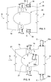
- FIG 5 it is shown a first variant of the combustor assembly 3, comprising at least two dampers 30 coupled to a combustor front panel 28 around the supply assembly 20.
- the dampers 30 are arranged so as the extension axis C is parallel to the longitudinal axis B.
- FIG 6 it is shown a second variant of the combustor assembly 3, comprising at least two dampers 30a, coupled to the combustor liner 18 and arranged on opposite sides of the liner 18 with respect to the longitudinal axis B, and at least one damper 30b arranged inside the inner chamber 27.
- Damper 30b is arranged inside the inner chamber 27 so as the extension axis C is transversal to the longitudinal axis B, while dampers 30a are arranged so as the extension axis C is orthogonal to the longitudinal axis B.
- FIG 7 it is shown a third variant of the combustor assembly 3 wherein the supply assembly 20 is defined by at least two burners 29 axially extending in the combustor assembly 3 which are supported by a combustor front panel 28.
- the combustor assembly 3 comprises a damper 30 arranged substantially along the longitudinal axis B between the burners 29. Extension axis C of the damper 30 preferably coincides with longitudinal axis B.Finally, it is clear that modifications and variants can be made to the damper and to the combustor assembly described herein without departing from the scope of the present invention, as defined in the appended claims.
Landscapes
- Engineering & Computer Science (AREA)
- Chemical & Material Sciences (AREA)
- Combustion & Propulsion (AREA)
- Mechanical Engineering (AREA)
- General Engineering & Computer Science (AREA)
Priority Applications (2)
| Application Number | Priority Date | Filing Date | Title |
|---|---|---|---|
| EP18210858.9A EP3663548B1 (de) | 2018-12-06 | 2018-12-06 | Dämpfer für eine brennkammeranordnung eines gasturbinenkraftwerks und brennkammeranordnung mit dem dämpfer |
| CN201911240889.XA CN111288492B (zh) | 2018-12-06 | 2019-12-06 | 用于燃烧器组件的阻尼器及包括所述阻尼器的燃烧器组件 |
Applications Claiming Priority (1)
| Application Number | Priority Date | Filing Date | Title |
|---|---|---|---|
| EP18210858.9A EP3663548B1 (de) | 2018-12-06 | 2018-12-06 | Dämpfer für eine brennkammeranordnung eines gasturbinenkraftwerks und brennkammeranordnung mit dem dämpfer |
Publications (2)
| Publication Number | Publication Date |
|---|---|
| EP3663548A1 true EP3663548A1 (de) | 2020-06-10 |
| EP3663548B1 EP3663548B1 (de) | 2022-05-25 |
Family
ID=64650306
Family Applications (1)
| Application Number | Title | Priority Date | Filing Date |
|---|---|---|---|
| EP18210858.9A Active EP3663548B1 (de) | 2018-12-06 | 2018-12-06 | Dämpfer für eine brennkammeranordnung eines gasturbinenkraftwerks und brennkammeranordnung mit dem dämpfer |
Country Status (2)
| Country | Link |
|---|---|
| EP (1) | EP3663548B1 (de) |
| CN (1) | CN111288492B (de) |
Citations (4)
| Publication number | Priority date | Publication date | Assignee | Title |
|---|---|---|---|---|
| EP2397761A1 (de) * | 2010-06-16 | 2011-12-21 | Alstom Technology Ltd | Helmholtz-Dämpfer und Verfahren zur Regelung der Resonanzfrequenz eines Helmholtz-Dämpfers |
| EP2397759A1 (de) * | 2010-06-16 | 2011-12-21 | Alstom Technology Ltd | Dämpfungsanordnung |
| EP2837883A1 (de) * | 2013-08-16 | 2015-02-18 | ALSTOM Technology Ltd | Vorgemischter Rohrbrenner mit wellenförmigen Vormischflügeln für die zweite Stufe einer sequentiellen Gasturbine |
| US20180156460A1 (en) * | 2016-12-02 | 2018-06-07 | General Electric Company | Method and apparatus for gas turbine combustor inner cap and high frequency acoustic dampers |
Family Cites Families (3)
| Publication number | Priority date | Publication date | Assignee | Title |
|---|---|---|---|---|
| CN104204677B (zh) * | 2012-03-30 | 2016-07-06 | 通用电器技术有限公司 | 装备有阻尼装置的燃烧器密封段 |
| EP2860449B1 (de) * | 2013-10-09 | 2018-04-04 | Ansaldo Energia Switzerland AG | Schalldämpfende Vorrichtung |
| EP2963345B1 (de) * | 2014-06-30 | 2018-09-19 | Ansaldo Energia Switzerland AG | Dämpfer für Gasturbine |
-
2018
- 2018-12-06 EP EP18210858.9A patent/EP3663548B1/de active Active
-
2019
- 2019-12-06 CN CN201911240889.XA patent/CN111288492B/zh active Active
Patent Citations (4)
| Publication number | Priority date | Publication date | Assignee | Title |
|---|---|---|---|---|
| EP2397761A1 (de) * | 2010-06-16 | 2011-12-21 | Alstom Technology Ltd | Helmholtz-Dämpfer und Verfahren zur Regelung der Resonanzfrequenz eines Helmholtz-Dämpfers |
| EP2397759A1 (de) * | 2010-06-16 | 2011-12-21 | Alstom Technology Ltd | Dämpfungsanordnung |
| EP2837883A1 (de) * | 2013-08-16 | 2015-02-18 | ALSTOM Technology Ltd | Vorgemischter Rohrbrenner mit wellenförmigen Vormischflügeln für die zweite Stufe einer sequentiellen Gasturbine |
| US20180156460A1 (en) * | 2016-12-02 | 2018-06-07 | General Electric Company | Method and apparatus for gas turbine combustor inner cap and high frequency acoustic dampers |
Also Published As
| Publication number | Publication date |
|---|---|
| CN111288492A (zh) | 2020-06-16 |
| EP3663548B1 (de) | 2022-05-25 |
| CN111288492B (zh) | 2022-11-08 |
Similar Documents
| Publication | Publication Date | Title |
|---|---|---|
| KR101576462B1 (ko) | 연소실 파동을 감소시키기 위한 댐퍼 장치 | |
| US8516819B2 (en) | Forward-section resonator for high frequency dynamic damping | |
| CN105074337B (zh) | 燃气涡轮发动机的燃烧器中的流量调节器 | |
| US10054313B2 (en) | Air biasing system in a gas turbine combustor | |
| US9200571B2 (en) | Fuel nozzle assembly for a gas turbine engine | |
| US9625158B2 (en) | Gas turbine combustion acoustic damping system | |
| JP5052783B2 (ja) | ガスタービンエンジンおよび燃料供給装置 | |
| JP2016121689A (ja) | 希釈用空気噴射部を有する軸方向段階混合器 | |
| US20130133331A1 (en) | System and method for reducing combustion dynamics in a turbomachine | |
| CN105715378A (zh) | 冷却和稀释空气的分开供给 | |
| WO2019025094A1 (en) | BURNER COMPRISING AN ACOUSTICAL DAMPER | |
| CN112178695B (zh) | 阻尼器、包括阻尼器的燃烧器组件及制造阻尼器的方法 | |
| JP6679233B2 (ja) | 多段燃焼器 | |
| US10323574B2 (en) | Mixer for admixing a dilution air to the hot gas flow | |
| EP3663548B1 (de) | Dämpfer für eine brennkammeranordnung eines gasturbinenkraftwerks und brennkammeranordnung mit dem dämpfer | |
| CN106338085A (zh) | 燃气涡轮发动机、及其所用的燃烧器筒组件以及制造方法 | |
| EP3974723B1 (de) | Gasturbine für kraftwerk mit einer dämpfungsvorrichtung | |
| EP3486567B1 (de) | Rohrbrenner für eine gasturbine und gasturbine mit solch einem rohrbrenner | |
| US20200124286A1 (en) | Fuel nozzle, and combustor and gas turbine having the same | |
| KR20150103032A (ko) | 헬름홀츠 공명기가 장착된 가스터빈 버너 조립체 | |
| CN116293819A (zh) | 具有谐振器的燃烧器 |
Legal Events
| Date | Code | Title | Description |
|---|---|---|---|
| PUAI | Public reference made under article 153(3) epc to a published international application that has entered the european phase |
Free format text: ORIGINAL CODE: 0009012 |
|
| STAA | Information on the status of an ep patent application or granted ep patent |
Free format text: STATUS: THE APPLICATION HAS BEEN PUBLISHED |
|
| AK | Designated contracting states |
Kind code of ref document: A1 Designated state(s): AL AT BE BG CH CY CZ DE DK EE ES FI FR GB GR HR HU IE IS IT LI LT LU LV MC MK MT NL NO PL PT RO RS SE SI SK SM TR |
|
| AX | Request for extension of the european patent |
Extension state: BA ME |
|
| STAA | Information on the status of an ep patent application or granted ep patent |
Free format text: STATUS: REQUEST FOR EXAMINATION WAS MADE |
|
| 17P | Request for examination filed |
Effective date: 20201209 |
|
| RBV | Designated contracting states (corrected) |
Designated state(s): AL AT BE BG CH CY CZ DE DK EE ES FI FR GB GR HR HU IE IS IT LI LT LU LV MC MK MT NL NO PL PT RO RS SE SI SK SM TR |
|
| STAA | Information on the status of an ep patent application or granted ep patent |
Free format text: STATUS: EXAMINATION IS IN PROGRESS |
|
| 17Q | First examination report despatched |
Effective date: 20210407 |
|
| GRAP | Despatch of communication of intention to grant a patent |
Free format text: ORIGINAL CODE: EPIDOSNIGR1 |
|
| STAA | Information on the status of an ep patent application or granted ep patent |
Free format text: STATUS: GRANT OF PATENT IS INTENDED |
|
| INTG | Intention to grant announced |
Effective date: 20211216 |
|
| GRAS | Grant fee paid |
Free format text: ORIGINAL CODE: EPIDOSNIGR3 |
|
| GRAA | (expected) grant |
Free format text: ORIGINAL CODE: 0009210 |
|
| STAA | Information on the status of an ep patent application or granted ep patent |
Free format text: STATUS: THE PATENT HAS BEEN GRANTED |
|
| AK | Designated contracting states |
Kind code of ref document: B1 Designated state(s): AL AT BE BG CH CY CZ DE DK EE ES FI FR GB GR HR HU IE IS IT LI LT LU LV MC MK MT NL NO PL PT RO RS SE SI SK SM TR |
|
| REG | Reference to a national code |
Ref country code: GB Ref legal event code: FG4D |
|
| REG | Reference to a national code |
Ref country code: CH Ref legal event code: EP |
|
| REG | Reference to a national code |
Ref country code: AT Ref legal event code: REF Ref document number: 1494340 Country of ref document: AT Kind code of ref document: T Effective date: 20220615 Ref country code: DE Ref legal event code: R096 Ref document number: 602018035939 Country of ref document: DE |
|
| REG | Reference to a national code |
Ref country code: IE Ref legal event code: FG4D |
|
| REG | Reference to a national code |
Ref country code: LT Ref legal event code: MG9D |
|
| REG | Reference to a national code |
Ref country code: NL Ref legal event code: MP Effective date: 20220525 |
|
| REG | Reference to a national code |
Ref country code: AT Ref legal event code: MK05 Ref document number: 1494340 Country of ref document: AT Kind code of ref document: T Effective date: 20220525 |
|
| PG25 | Lapsed in a contracting state [announced via postgrant information from national office to epo] |
Ref country code: SE Free format text: LAPSE BECAUSE OF FAILURE TO SUBMIT A TRANSLATION OF THE DESCRIPTION OR TO PAY THE FEE WITHIN THE PRESCRIBED TIME-LIMIT Effective date: 20220525 Ref country code: PT Free format text: LAPSE BECAUSE OF FAILURE TO SUBMIT A TRANSLATION OF THE DESCRIPTION OR TO PAY THE FEE WITHIN THE PRESCRIBED TIME-LIMIT Effective date: 20220926 Ref country code: NO Free format text: LAPSE BECAUSE OF FAILURE TO SUBMIT A TRANSLATION OF THE DESCRIPTION OR TO PAY THE FEE WITHIN THE PRESCRIBED TIME-LIMIT Effective date: 20220825 Ref country code: NL Free format text: LAPSE BECAUSE OF FAILURE TO SUBMIT A TRANSLATION OF THE DESCRIPTION OR TO PAY THE FEE WITHIN THE PRESCRIBED TIME-LIMIT Effective date: 20220525 Ref country code: LT Free format text: LAPSE BECAUSE OF FAILURE TO SUBMIT A TRANSLATION OF THE DESCRIPTION OR TO PAY THE FEE WITHIN THE PRESCRIBED TIME-LIMIT Effective date: 20220525 Ref country code: HR Free format text: LAPSE BECAUSE OF FAILURE TO SUBMIT A TRANSLATION OF THE DESCRIPTION OR TO PAY THE FEE WITHIN THE PRESCRIBED TIME-LIMIT Effective date: 20220525 Ref country code: GR Free format text: LAPSE BECAUSE OF FAILURE TO SUBMIT A TRANSLATION OF THE DESCRIPTION OR TO PAY THE FEE WITHIN THE PRESCRIBED TIME-LIMIT Effective date: 20220826 Ref country code: FI Free format text: LAPSE BECAUSE OF FAILURE TO SUBMIT A TRANSLATION OF THE DESCRIPTION OR TO PAY THE FEE WITHIN THE PRESCRIBED TIME-LIMIT Effective date: 20220525 Ref country code: ES Free format text: LAPSE BECAUSE OF FAILURE TO SUBMIT A TRANSLATION OF THE DESCRIPTION OR TO PAY THE FEE WITHIN THE PRESCRIBED TIME-LIMIT Effective date: 20220525 Ref country code: BG Free format text: LAPSE BECAUSE OF FAILURE TO SUBMIT A TRANSLATION OF THE DESCRIPTION OR TO PAY THE FEE WITHIN THE PRESCRIBED TIME-LIMIT Effective date: 20220825 Ref country code: AT Free format text: LAPSE BECAUSE OF FAILURE TO SUBMIT A TRANSLATION OF THE DESCRIPTION OR TO PAY THE FEE WITHIN THE PRESCRIBED TIME-LIMIT Effective date: 20220525 |
|
| PG25 | Lapsed in a contracting state [announced via postgrant information from national office to epo] |
Ref country code: RS Free format text: LAPSE BECAUSE OF FAILURE TO SUBMIT A TRANSLATION OF THE DESCRIPTION OR TO PAY THE FEE WITHIN THE PRESCRIBED TIME-LIMIT Effective date: 20220525 Ref country code: PL Free format text: LAPSE BECAUSE OF FAILURE TO SUBMIT A TRANSLATION OF THE DESCRIPTION OR TO PAY THE FEE WITHIN THE PRESCRIBED TIME-LIMIT Effective date: 20220525 Ref country code: LV Free format text: LAPSE BECAUSE OF FAILURE TO SUBMIT A TRANSLATION OF THE DESCRIPTION OR TO PAY THE FEE WITHIN THE PRESCRIBED TIME-LIMIT Effective date: 20220525 Ref country code: IS Free format text: LAPSE BECAUSE OF FAILURE TO SUBMIT A TRANSLATION OF THE DESCRIPTION OR TO PAY THE FEE WITHIN THE PRESCRIBED TIME-LIMIT Effective date: 20220925 |
|
| PG25 | Lapsed in a contracting state [announced via postgrant information from national office to epo] |
Ref country code: SM Free format text: LAPSE BECAUSE OF FAILURE TO SUBMIT A TRANSLATION OF THE DESCRIPTION OR TO PAY THE FEE WITHIN THE PRESCRIBED TIME-LIMIT Effective date: 20220525 Ref country code: SK Free format text: LAPSE BECAUSE OF FAILURE TO SUBMIT A TRANSLATION OF THE DESCRIPTION OR TO PAY THE FEE WITHIN THE PRESCRIBED TIME-LIMIT Effective date: 20220525 Ref country code: RO Free format text: LAPSE BECAUSE OF FAILURE TO SUBMIT A TRANSLATION OF THE DESCRIPTION OR TO PAY THE FEE WITHIN THE PRESCRIBED TIME-LIMIT Effective date: 20220525 Ref country code: EE Free format text: LAPSE BECAUSE OF FAILURE TO SUBMIT A TRANSLATION OF THE DESCRIPTION OR TO PAY THE FEE WITHIN THE PRESCRIBED TIME-LIMIT Effective date: 20220525 Ref country code: DK Free format text: LAPSE BECAUSE OF FAILURE TO SUBMIT A TRANSLATION OF THE DESCRIPTION OR TO PAY THE FEE WITHIN THE PRESCRIBED TIME-LIMIT Effective date: 20220525 Ref country code: CZ Free format text: LAPSE BECAUSE OF FAILURE TO SUBMIT A TRANSLATION OF THE DESCRIPTION OR TO PAY THE FEE WITHIN THE PRESCRIBED TIME-LIMIT Effective date: 20220525 |
|
| REG | Reference to a national code |
Ref country code: DE Ref legal event code: R097 Ref document number: 602018035939 Country of ref document: DE |
|
| PG25 | Lapsed in a contracting state [announced via postgrant information from national office to epo] |
Ref country code: AL Free format text: LAPSE BECAUSE OF FAILURE TO SUBMIT A TRANSLATION OF THE DESCRIPTION OR TO PAY THE FEE WITHIN THE PRESCRIBED TIME-LIMIT Effective date: 20220525 |
|
| PLBE | No opposition filed within time limit |
Free format text: ORIGINAL CODE: 0009261 |
|
| STAA | Information on the status of an ep patent application or granted ep patent |
Free format text: STATUS: NO OPPOSITION FILED WITHIN TIME LIMIT |
|
| 26N | No opposition filed |
Effective date: 20230228 |
|
| PG25 | Lapsed in a contracting state [announced via postgrant information from national office to epo] |
Ref country code: SI Free format text: LAPSE BECAUSE OF FAILURE TO SUBMIT A TRANSLATION OF THE DESCRIPTION OR TO PAY THE FEE WITHIN THE PRESCRIBED TIME-LIMIT Effective date: 20220525 |
|
| REG | Reference to a national code |
Ref country code: CH Ref legal event code: PL |
|
| REG | Reference to a national code |
Ref country code: BE Ref legal event code: MM Effective date: 20221231 |
|
| PG25 | Lapsed in a contracting state [announced via postgrant information from national office to epo] |
Ref country code: LU Free format text: LAPSE BECAUSE OF NON-PAYMENT OF DUE FEES Effective date: 20221206 |
|
| PG25 | Lapsed in a contracting state [announced via postgrant information from national office to epo] |
Ref country code: LI Free format text: LAPSE BECAUSE OF NON-PAYMENT OF DUE FEES Effective date: 20221231 Ref country code: IE Free format text: LAPSE BECAUSE OF NON-PAYMENT OF DUE FEES Effective date: 20221206 Ref country code: CH Free format text: LAPSE BECAUSE OF NON-PAYMENT OF DUE FEES Effective date: 20221231 |
|
| PG25 | Lapsed in a contracting state [announced via postgrant information from national office to epo] |
Ref country code: FR Free format text: LAPSE BECAUSE OF NON-PAYMENT OF DUE FEES Effective date: 20221231 Ref country code: BE Free format text: LAPSE BECAUSE OF NON-PAYMENT OF DUE FEES Effective date: 20221231 |
|
| PG25 | Lapsed in a contracting state [announced via postgrant information from national office to epo] |
Ref country code: HU Free format text: LAPSE BECAUSE OF FAILURE TO SUBMIT A TRANSLATION OF THE DESCRIPTION OR TO PAY THE FEE WITHIN THE PRESCRIBED TIME-LIMIT; INVALID AB INITIO Effective date: 20181206 |
|
| PG25 | Lapsed in a contracting state [announced via postgrant information from national office to epo] |
Ref country code: CY Free format text: LAPSE BECAUSE OF FAILURE TO SUBMIT A TRANSLATION OF THE DESCRIPTION OR TO PAY THE FEE WITHIN THE PRESCRIBED TIME-LIMIT Effective date: 20220525 |
|
| PG25 | Lapsed in a contracting state [announced via postgrant information from national office to epo] |
Ref country code: MK Free format text: LAPSE BECAUSE OF FAILURE TO SUBMIT A TRANSLATION OF THE DESCRIPTION OR TO PAY THE FEE WITHIN THE PRESCRIBED TIME-LIMIT Effective date: 20220525 |
|
| P01 | Opt-out of the competence of the unified patent court (upc) registered |
Effective date: 20240430 |
|
| PG25 | Lapsed in a contracting state [announced via postgrant information from national office to epo] |
Ref country code: MC Free format text: LAPSE BECAUSE OF FAILURE TO SUBMIT A TRANSLATION OF THE DESCRIPTION OR TO PAY THE FEE WITHIN THE PRESCRIBED TIME-LIMIT Effective date: 20220525 |
|
| PG25 | Lapsed in a contracting state [announced via postgrant information from national office to epo] |
Ref country code: MC Free format text: LAPSE BECAUSE OF FAILURE TO SUBMIT A TRANSLATION OF THE DESCRIPTION OR TO PAY THE FEE WITHIN THE PRESCRIBED TIME-LIMIT Effective date: 20220525 |
|
| PG25 | Lapsed in a contracting state [announced via postgrant information from national office to epo] |
Ref country code: MT Free format text: LAPSE BECAUSE OF FAILURE TO SUBMIT A TRANSLATION OF THE DESCRIPTION OR TO PAY THE FEE WITHIN THE PRESCRIBED TIME-LIMIT Effective date: 20220525 |
|
| PG25 | Lapsed in a contracting state [announced via postgrant information from national office to epo] |
Ref country code: BG Free format text: LAPSE BECAUSE OF FAILURE TO SUBMIT A TRANSLATION OF THE DESCRIPTION OR TO PAY THE FEE WITHIN THE PRESCRIBED TIME-LIMIT Effective date: 20220525 |
|
| PG25 | Lapsed in a contracting state [announced via postgrant information from national office to epo] |
Ref country code: BG Free format text: LAPSE BECAUSE OF FAILURE TO SUBMIT A TRANSLATION OF THE DESCRIPTION OR TO PAY THE FEE WITHIN THE PRESCRIBED TIME-LIMIT Effective date: 20220525 |
|
| PG25 | Lapsed in a contracting state [announced via postgrant information from national office to epo] |
Ref country code: TR Free format text: LAPSE BECAUSE OF FAILURE TO SUBMIT A TRANSLATION OF THE DESCRIPTION OR TO PAY THE FEE WITHIN THE PRESCRIBED TIME-LIMIT Effective date: 20220525 |
|
| PGFP | Annual fee paid to national office [announced via postgrant information from national office to epo] |
Ref country code: GB Payment date: 20251218 Year of fee payment: 8 |
|
| PGFP | Annual fee paid to national office [announced via postgrant information from national office to epo] |
Ref country code: DE Payment date: 20251222 Year of fee payment: 8 |
|
| PGFP | Annual fee paid to national office [announced via postgrant information from national office to epo] |
Ref country code: IT Payment date: 20251231 Year of fee payment: 8 |