EP3663575A1 - Système de transport pour une nacelle d'une éolienne et procédé de transport d'une nacelle d'une éolienne - Google Patents
Système de transport pour une nacelle d'une éolienne et procédé de transport d'une nacelle d'une éolienne Download PDFInfo
- Publication number
- EP3663575A1 EP3663575A1 EP18210448.9A EP18210448A EP3663575A1 EP 3663575 A1 EP3663575 A1 EP 3663575A1 EP 18210448 A EP18210448 A EP 18210448A EP 3663575 A1 EP3663575 A1 EP 3663575A1
- Authority
- EP
- European Patent Office
- Prior art keywords
- transport
- support
- unit
- machine
- carrier
- Prior art date
- Legal status (The legal status is an assumption and is not a legal conclusion. Google has not performed a legal analysis and makes no representation as to the accuracy of the status listed.)
- Granted
Links
Images




Classifications
-
- F—MECHANICAL ENGINEERING; LIGHTING; HEATING; WEAPONS; BLASTING
- F03—MACHINES OR ENGINES FOR LIQUIDS; WIND, SPRING, OR WEIGHT MOTORS; PRODUCING MECHANICAL POWER OR A REACTIVE PROPULSIVE THRUST, NOT OTHERWISE PROVIDED FOR
- F03D—WIND MOTORS
- F03D13/00—Assembly, mounting or commissioning of wind motors; Arrangements specially adapted for transporting wind motor components
- F03D13/40—Arrangements or methods specially adapted for transporting wind motor components
-
- F—MECHANICAL ENGINEERING; LIGHTING; HEATING; WEAPONS; BLASTING
- F03—MACHINES OR ENGINES FOR LIQUIDS; WIND, SPRING, OR WEIGHT MOTORS; PRODUCING MECHANICAL POWER OR A REACTIVE PROPULSIVE THRUST, NOT OTHERWISE PROVIDED FOR
- F03D—WIND MOTORS
- F03D13/00—Assembly, mounting or commissioning of wind motors; Arrangements specially adapted for transporting wind motor components
- F03D13/10—Assembly of wind motors; Arrangements for erecting wind motors
-
- F—MECHANICAL ENGINEERING; LIGHTING; HEATING; WEAPONS; BLASTING
- F03—MACHINES OR ENGINES FOR LIQUIDS; WIND, SPRING, OR WEIGHT MOTORS; PRODUCING MECHANICAL POWER OR A REACTIVE PROPULSIVE THRUST, NOT OTHERWISE PROVIDED FOR
- F03D—WIND MOTORS
- F03D80/00—Details, components or accessories not provided for in groups F03D1/00 - F03D17/00
-
- Y—GENERAL TAGGING OF NEW TECHNOLOGICAL DEVELOPMENTS; GENERAL TAGGING OF CROSS-SECTIONAL TECHNOLOGIES SPANNING OVER SEVERAL SECTIONS OF THE IPC; TECHNICAL SUBJECTS COVERED BY FORMER USPC CROSS-REFERENCE ART COLLECTIONS [XRACs] AND DIGESTS
- Y02—TECHNOLOGIES OR APPLICATIONS FOR MITIGATION OR ADAPTATION AGAINST CLIMATE CHANGE
- Y02B—CLIMATE CHANGE MITIGATION TECHNOLOGIES RELATED TO BUILDINGS, e.g. HOUSING, HOUSE APPLIANCES OR RELATED END-USER APPLICATIONS
- Y02B10/00—Integration of renewable energy sources in buildings
- Y02B10/30—Wind power
-
- Y—GENERAL TAGGING OF NEW TECHNOLOGICAL DEVELOPMENTS; GENERAL TAGGING OF CROSS-SECTIONAL TECHNOLOGIES SPANNING OVER SEVERAL SECTIONS OF THE IPC; TECHNICAL SUBJECTS COVERED BY FORMER USPC CROSS-REFERENCE ART COLLECTIONS [XRACs] AND DIGESTS
- Y02—TECHNOLOGIES OR APPLICATIONS FOR MITIGATION OR ADAPTATION AGAINST CLIMATE CHANGE
- Y02E—REDUCTION OF GREENHOUSE GAS [GHG] EMISSIONS, RELATED TO ENERGY GENERATION, TRANSMISSION OR DISTRIBUTION
- Y02E10/00—Energy generation through renewable energy sources
- Y02E10/70—Wind energy
- Y02E10/72—Wind turbines with rotation axis in wind direction
Definitions
- the present invention is in the field of the transport of large components of a wind turbine on the road, rail or by sea, as well as their storage and loading.
- the invention relates to a transport system for a nacelle of a wind energy installation and a method for transporting a nacelle of a wind energy installation.
- a wind turbine is usually composed of individual components with a high mass and very large dimensions.
- the components can include, for example, individual parts of the tower, the nacelle, the rotor hub and the rotor blades. These components are usually each pre-assembled, placed on a transport system and attached to it.
- the transport system with the machine house which consists, among other things, of the machine carrier, the generator carrier and the machine house cladding, is transported on the road with standard trailers and heavy-duty trucks, by rail freight wagons on the rail network or by sea by freight ships.
- the transport dimensions are limited to the standard transport vehicles, which is why a transport system must be adapted to these restrictions.
- EP 2505823 B1 discloses a transport frame for a nacelle / rotor hub unit of a wind turbine, the nacelle and the rotor hub being connected to one another.
- the transport frame includes a main support for supporting the weight of the Gondola / rotor hub unit, lateral stabilizing elements, a holding device for fastening the gondola / rotor hub unit and at least three fastening points for a hoist.
- An already assembled nacelle / rotor hub unit is lowered into the space formed between the lateral stabilizing elements with a lifting device and the holding device is attached to the nacelle.
- the patent publication WO 2011/076238 A1 discloses a support arrangement for unloading and loading tower segments of the tower of a wind turbine and comprises a support element and an adapter element.
- the adapter element is attached to the arcuate flange area of the tower segment.
- the support element is adjustable in height, so that the support arrangement can be parked and the means of transport can move out from under the supported tower segment.
- EP 2038548 B1 discloses a lifting device with height-adjustable legs for a nacelle of a wind turbine.
- the lifting device engages laterally in the lower structure of the supporting structure of the nacelle by lifting devices of the lifting device latching into handling openings in the supporting structure.
- the lifting device is equipped with hydraulic cylinders to lift the nacelle, for example so that a transport vehicle can be loaded.
- the transport system is connected to a truck and comprises two transport units, which are provided with wheels, and a basic structure.
- the basic structure is suspended between the transport units and is suitable for carrying and connecting to the nacelle to be transported.
- the basic structure has a frame structure and a connecting means for fastening the nacelle of the wind turbine.
- the frame construction is a square frame made of I-profiles with a protruding part, which is mechanical with the transport units can be connected and a cylindrical flange for connection to the nacelle.
- the frame can have several cross members.
- the basic structure is provided with a kind of support means / legs which are attached to the frame directly or with the aid of extension devices in order to lower or raise the basic structure vertically.
- the basic structure is attached to the gondola during manufacture of the gondola and remains on the gondola during the entire assembly and storage of the fully assembled gondola.
- the invention has for its object to develop a transport system for a nacelle of a wind turbine, which enables simple transportation of the nacelle both in production and to the building site without having to change the transport system.
- the difficulty in developing a transport system is to transport a component with high mass and the largest possible dimensions in limited transport dimensions on standard transport vehicles. Furthermore, the entire life cycle of the component, from production to intermediate storage, road transport, rail transport, sea transport, construction and dismantling with return, should be carried out in a cost-optimized manner.
- the invention is also intended to simplify the circulation of the transport system to the production site and back from the construction site.
- a transport system for a nacelle of a wind turbine is claimed.
- the nacelle includes in the sense the invention, in addition to other components not relevant to the invention, a generator support and a machine support as a support structure and / or a machine house cladding.
- the term "machine house” usually encompasses all components that are located above the interface to the tower head with the exception of the wind rotor (rotor hub, rotor blades).
- this also includes the supporting structure, the drive train with the fast shaft, the gearbox, the slow shaft and the generator, all electrical, mechanical and hydraulic components that are arranged inside the machine house cladding or on the outside of the machine house cladding , which should be disregarded here.
- the transport system comprises at least two transport units, which are not connected to each other but each form a unit.
- a rear transport unit can be connected to the generator carrier and a front transport unit can be connected to the machine carrier.
- the rear transport unit comprises a rear hollow profile with two identical, but laterally reversed rear support units which are fixedly but releasably arranged on the hollow profile and which can be connected to the generator carrier
- the front transport unit comprises a front hollow profile with two fixed but detachable on the hollow profile arranged, identical, but laterally reversed front support units which can be connected to the machine frame.
- the structure of the front and rear transport units is adapted to the machine frame or the generator frame.
- the rear transport unit and the front transport unit have guide pins which correspond to openings / bores in the generator carrier and in the machine carrier.
- each rear support unit essentially consists of a transport foot and a transport support, with a base part of the transport foot receiving the hollow profile with the aid of connecting means is releasably fixed or fixable on the hollow profile.
- Each rear transport support is connected on the one hand to the base part of the transport foot and, on the other hand, an end plate is detachably attached to its upper end.
- each front support unit essentially consists of a transport foot and a front transport support, a base part of the transport foot receiving the hollow profile being releasably fixed or fixable on the hollow profile with the aid of connecting means.
- Each front transport support is connected on the one hand to the base part of the transport foot and, on the other hand, is provided with bores at its upper end, which serve to fix the machine support by means of connecting means.
- a guide pin is arranged centrally on the base part.
- the method according to the invention for the transport of a machine house of a wind energy installation which comprises a generator carrier and a machine carrier and / or a machine house cladding, is carried out using the transport system according to the invention.
- the generator carrier is or is positioned on and connected to a rear transport unit of the transport system, openings on the underside of the generator carrier corresponding to the transport unit
- the machine carrier is or is positioned on and connected to a front transport unit of the transport system, with bores correspond to the transport unit on the underside of the machine carrier.
- the machine carrier and the generator carrier are placed individually and separately or as a combined unit with the generator carrier and the machine carrier and / or the machine house cladding.
- the transport system and the machine house remain connected from production to the construction site.
- the transport units, the rear and the front are connected to the generator support and the machine support through the nacelle casing.
- the transport system enables the nacelle to be transported over the entire life cycle. It is also possible to carry out the transport with standard trucks, rail freight cars and cargo ships with simple load securing.
- the transport system 1 is used for the safe road, rail and sea transport of a machine house. According to the invention, the transport system 1 is described by way of example, which optimally implements the transport of the machine house, including the large components machine carrier MT, generator carrier GT and machine house cladding 5, with a height limitation of 4 m over the entire life cycle.
- the transport system 1 consists of two rear transport units 2 and two front transport units 3, each of which is connected to one another via a hollow profile 4 (cross profile).
- FIG 1 shows a transport system 1 according to the invention, which, when fully assembled, is ready to accommodate a machine house.
- the transport system 1 consists of a rear transport unit 2, which serves to receive the generator carrier GT, and a front transport unit 3, which serves to receive the machine carrier MT.
- the transport units 2 and 3 are not connected to each other and each form a unit. Nevertheless, those parts of the transport units 2 and 3 which are provided with the same reference numerals are the same.
- Each transport unit 2 and 3 consists of an elongated hollow profile 4 (see also Figure 2 ) on which the other components are attached.
- On the hollow profile 4 of the rear transport unit 2 are two identical, but reversed Support units 200 fixed, but releasably arranged.
- a support unit 200 essentially consists of a transport foot 201 and a transport support 206.
- a support unit 300 consists essentially of a transport foot 301 and a transport support 306. The support units 200, 300 are in the Figures 3 to 5 considered in more detail.
- Figure 2 shows the hollow profile 4 for a rear or a front transport unit 2, 3, which in this embodiment has a length of 4000mm, a width of 260mm and a height of 140mm, in a perspective view.
- Transport eyelets 401 can be detachably connected to the hollow profile 4 at the outer ends. The transport eyelets 401 are used to fasten the transport units 2, 3 on the transport vehicle, not shown here. Lateral bores 402 are also provided for fastening the transport feet 201, 301 of the support units 200, 300.
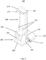
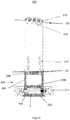
- FIG 3 is a perspective view of a support unit 200 of a rear transport unit 2 and in Figure 4 Details of the connection of a support unit 200 to the machine house can be seen in a sectional illustration.
- Two support units 200 are required, which are arranged on the hollow profile 4 opposite and facing each other.
- the height of the support units 200 corresponds to the height of the generator support GT at the point to be fastened and can be adjusted accordingly.
- a support unit 200 essentially consists of a transport foot 201 and a transport support 206.
- the transport foot 201 consists of a base part 202 with a lower plate 203, on which two side cover plates 204 are arranged, and an upper plate 205, which lies between the side cover plates 204 is inserted.
- the hollow profile is in the resulting cavity between the lower plate 203, the side cover plates 204 and the upper plate 205 4 received or pushed and fixed there with the aid of connecting means 403.
- a transport eyelet 211 is laterally connected to the base part 202.
- the side cover plates 204 protrude beyond the height of the hollow profile 4, so that they can serve to stiffen the transport support 206, which is inserted into a cutout 207 of the side cover plates 204 and fixed there.
- the transport support 206 is provided at its upper end 214 with an end plate 208 which is detachably fastened with the aid of connecting means 216.
- a plurality of bores 215 are made in the transport support 206 on its upper end 214, which correspond to the end plate 208.
- the position of the support units 200 and thus the transport support 206 on the hollow profile 4 corresponds to openings in the machine house cladding 5 and can be changed.
- the two side cover plates 204 are fixedly connected in front of the transport support 206 by a plate 209 and arranged on the hollow profile 4 pointing towards one another.
- the plate 209 of the right and the left transport foot 201 two guide mandrels 210 are introduced upwards.
- the generator carrier GT is later placed on the guide mandrels 210, thereby preventing the transport system 1 from tipping over when the generator carrier GT or the machine house are being placed and removed.
- the end plates 208 of the two support units 200 face inward. The end plates 208 are placed and screwed into the transport system 1 after the generator carrier GT has been inserted, so that the generator carrier GT can be secured upward.
- FIG 4 details of the connection of a rear support unit 200 to the machine house can be seen.
- the transport bracket 206 is with the lower one Plate 203 firmly connected.
- the guide mandrels 210 are connected to the generator carrier GT.
- the end plate 208 can also be seen.
- the end plate 208 is fastened to the upper end 214 of the transport support 206 with the connecting means 216 and thus secures the generator support GT.
- the hollow profile 4 is secured in the base part 202 by connecting means 403.
- FIG. 5 A perspective view of a support unit 300 of a front transport unit 3 can be seen.
- Two supporting units 300 are required, which are arranged opposite one another and facing one another on the hollow profile 4.
- the height of the support units 300 is adapted to the structural conditions of the machine carrier MT at the attachment point.
- a support unit 300 essentially consists of a transport foot 301 and a transport support 306.
- the transport foot 301 consists of a base part 302 with a lower plate 303, on which two side cover plates 304 are arranged, and an upper plate 305, which is on the side cover plates 304 arranged and firmly connected to them.
- the hollow profile 4 is received or pushed into the resulting cavity between the lower plate 303, the side cover plates 304 and the upper plate 305 and fixed there with the aid of connecting means 403.
- a transport eyelet 311 is laterally connected to the base part 302.
- the transport support 306 is fixedly arranged on the base part 302.
- the transport support 306 corresponds to openings in the machine house cladding 5 and the machine support MT.
- the upper end 307 of the closed transport support 306 is provided with a plurality of bores 308, a central bore 308 receiving a guide mandrel 310.
- the guide mandrel 310 serves to guide the machine carrier MT when it is placed on the transport system 1.
- the other bores 308 serve to fix the machine carrier MT by means of connecting means 309.
- the Figure 6 shows the rear transport unit 2 and the Figure 7 shows the front transport unit 3 each in a perspective view.
- the support units 200, 300 are fastened in the lateral bores 402 of the hollow profiles 4 with the aid of the connecting means 403.
- the connecting means 403 are hexagon screws, but other connecting means 403 are also conceivable, such as, for example, safety pins or safety bolts.
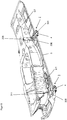
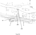
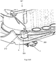
- FIG 8 the transport system 1 is shown with a part of the machine house to be transported, the drawing is cut at the level of the machine support MT.
- the rear transport unit 2 and the front transport unit 3 protrude upward through corresponding openings 501 in the machine house cladding 5.
- the generator support GT rests on the plates 209 of the right and left transport feet 201 and the upwardly directed guide pins 210 are received through existing openings in the generator support GT.
- the transport supports 206 of the rear transport unit 2 are guided past the generator carrier GT such that the generator carrier GT can be fixed by the end plate 208.
- the machine carrier MT rests on the front transport unit 3.
- the transport supports 306 are guided through openings 501 in the machine house cladding 5.
- the machine carrier MT rests on the upper ends 307 of the support units 300 and the guide mandrels 310 directed upwards are received by existing bores in the machine carrier MT.
- the machine carrier MT is releasably fixed on the upper ends 307 of the support units 300 by means of the connecting means 309.
- the Figures 8-A and 8-B show detailed views Figure 8 .
- the transport system 1 is provided in production.
- the transport units 2 and 3 can be used either before or after the assembly of the machine carrier MT and generator carrier GT these are connected.
- the rear transport unit 2 is securely connected to the generator carrier GT via four guide pins 210 and two end plates 208.
- the front transport unit 3 is connected to the machine carrier MT via eight connecting means 309, for example screws, and two guide pins 310. If the transport units 2 and 3 are attached after the assembly of the machine carrier MT and generator carrier GT, the hollow profiles 4 are subsequently inserted into the support units 200, 300 and fastened.
- the nacelle runs with the transport system 1 over the entire production line up to the removal.
- the machine house with the transport system 1 is lifted onto the means of transport, for example a truck, a rail freight car or a ship, with the aid of lifting means which are attached to the machine house and secured there.
- the means of transport for example a truck, a rail freight car or a ship
- Load securing during road or rail transport is carried out on the transport system 1 by means of standard lashing chains.
- the nacelle is placed on the transport system 1 on a trailer or freight wagon approved for the load.
- the load can be supported with anti-slip mats on the contact surfaces and is secured in position with tensioned chains.
- the nacelle In the case of sea transport, the nacelle is loaded directly onto the ship's deck using transport system 1 in an area approved for the load. Load securing against slipping is implemented using stop plates welded to the ship's deck.
- the connection of the transport system 1 is released from the machine house.
- the guide pins 210, 310 secure the machine house and prevent damage to the GRP machine house cladding when it is lifted off.
- the transport of the transport system 1 for production and the storage of the transport system 1 can be carried out with commercially available tarpaulin trucks.
- the individual components of the transport units 2, 3, such as hollow profile 4, support units 200, 300 or the assembled transport units 2, 3, are secured with anti-slip mats and lashing means so that they do not slip when braking, cornering, accelerating, etc. is possible.
- the transport units 2, 3 can be lifted or transported and stored in the individual components of the hollow profile 4, support units 200, 300 or as an assembly.
- the described transport eyelets 211, 311, 401 can be used for this.
- eyebolts can additionally be screwed into the bores 308, 214 of the transport supports 206, 306. These eyebolts are deposited, for example, on the rear transport unit 2 when not in use.
- the transport system 1 is aligned on the crane footprint and the nacelle is lowered via the guide mandrels 210, 310. Subsequently, the machine house with the rear transport unit 2 is secured on the generator carrier GT via the two end plates 208. The front transport unit 3 is connected and secured to the machine carrier MT via the connecting means 309.
Landscapes
- Engineering & Computer Science (AREA)
- Life Sciences & Earth Sciences (AREA)
- Sustainable Development (AREA)
- Sustainable Energy (AREA)
- Chemical & Material Sciences (AREA)
- Combustion & Propulsion (AREA)
- Mechanical Engineering (AREA)
- General Engineering & Computer Science (AREA)
- Wind Motors (AREA)
Priority Applications (2)
| Application Number | Priority Date | Filing Date | Title |
|---|---|---|---|
| ES18210448T ES2882132T3 (es) | 2018-12-05 | 2018-12-05 | Sistema de transporte para una góndola de un aerogenerador y procedimiento para el transporte de una góndola de un aerogenerador |
| EP18210448.9A EP3663575B1 (fr) | 2018-12-05 | 2018-12-05 | Système de transport pour une nacelle d'une éolienne et procédé de transport d'une nacelle d'une éolienne |
Applications Claiming Priority (1)
| Application Number | Priority Date | Filing Date | Title |
|---|---|---|---|
| EP18210448.9A EP3663575B1 (fr) | 2018-12-05 | 2018-12-05 | Système de transport pour une nacelle d'une éolienne et procédé de transport d'une nacelle d'une éolienne |
Publications (2)
| Publication Number | Publication Date |
|---|---|
| EP3663575A1 true EP3663575A1 (fr) | 2020-06-10 |
| EP3663575B1 EP3663575B1 (fr) | 2021-05-12 |
Family
ID=64606863
Family Applications (1)
| Application Number | Title | Priority Date | Filing Date |
|---|---|---|---|
| EP18210448.9A Active EP3663575B1 (fr) | 2018-12-05 | 2018-12-05 | Système de transport pour une nacelle d'une éolienne et procédé de transport d'une nacelle d'une éolienne |
Country Status (2)
| Country | Link |
|---|---|
| EP (1) | EP3663575B1 (fr) |
| ES (1) | ES2882132T3 (fr) |
Citations (6)
| Publication number | Priority date | Publication date | Assignee | Title |
|---|---|---|---|---|
| WO2010069611A1 (fr) * | 2008-12-16 | 2010-06-24 | Siemens Aktiengesellschaft | Système et procédé pour manipuler une nacelle d'une éolienne |
| WO2011076238A1 (fr) | 2009-12-23 | 2011-06-30 | Powerwind Gmbh | Pieds de transport réglables |
| DE102011013844A1 (de) * | 2011-03-14 | 2012-09-20 | Repower Systems Ag | Transportgestell für den Triebstrang einer Windenergieanlage |
| EP2373520B1 (fr) | 2008-12-09 | 2014-04-09 | Vestas Wind Systems A/S | Système de transport |
| EP2038548B1 (fr) | 2006-06-29 | 2016-11-02 | Vestas Wind Systems A/S | Système de déplacement d'une nacelle d'éolienne, procédé de déplacement vertical d'une nacelle d'éolienne et nacelle d'éolienne |
| EP2505823B1 (fr) | 2011-03-30 | 2018-06-20 | General Electric Company | Trame de transport pour unité de moyeu de rotor/nacelle d'une éolienne, procédé de transport et de montage d'une unité de moyeu de rotor/nacelle |
-
2018
- 2018-12-05 ES ES18210448T patent/ES2882132T3/es active Active
- 2018-12-05 EP EP18210448.9A patent/EP3663575B1/fr active Active
Patent Citations (6)
| Publication number | Priority date | Publication date | Assignee | Title |
|---|---|---|---|---|
| EP2038548B1 (fr) | 2006-06-29 | 2016-11-02 | Vestas Wind Systems A/S | Système de déplacement d'une nacelle d'éolienne, procédé de déplacement vertical d'une nacelle d'éolienne et nacelle d'éolienne |
| EP2373520B1 (fr) | 2008-12-09 | 2014-04-09 | Vestas Wind Systems A/S | Système de transport |
| WO2010069611A1 (fr) * | 2008-12-16 | 2010-06-24 | Siemens Aktiengesellschaft | Système et procédé pour manipuler une nacelle d'une éolienne |
| WO2011076238A1 (fr) | 2009-12-23 | 2011-06-30 | Powerwind Gmbh | Pieds de transport réglables |
| DE102011013844A1 (de) * | 2011-03-14 | 2012-09-20 | Repower Systems Ag | Transportgestell für den Triebstrang einer Windenergieanlage |
| EP2505823B1 (fr) | 2011-03-30 | 2018-06-20 | General Electric Company | Trame de transport pour unité de moyeu de rotor/nacelle d'une éolienne, procédé de transport et de montage d'une unité de moyeu de rotor/nacelle |
Also Published As
| Publication number | Publication date |
|---|---|
| EP3663575B1 (fr) | 2021-05-12 |
| ES2882132T3 (es) | 2021-12-01 |
Similar Documents
| Publication | Publication Date | Title |
|---|---|---|
| EP2441701B1 (fr) | Dispositif de transport et moyen de transport avec un tel dispositif | |
| EP2456973B1 (fr) | Procédé et dispositif permettant le transport et le montage d'éoliennes | |
| DE60011737T3 (de) | Methode zum Montieren der Komponenten einer Windkraftanlage | |
| DE69619695T2 (de) | Jettriebwerkstransportvorrichtung | |
| DE60301950T3 (de) | Verfahren zum transport einer windturbinengondel und verwendung hiervon | |
| EP2708731A2 (fr) | Procédé et dispositif de transport d'une pale de rotor d'une installation éolienne | |
| EP2248754A1 (fr) | Grue télescopique dotée d'un dispositif d'ancrage à montage automatique et procédé de montage d'un dispositif d'ancrage | |
| DE8911634U1 (de) | In Teilen transportierbares Vergnügungsgerät für Jahrmärkte od.dgl., insbesondere Riesenrad | |
| EP3499027B1 (fr) | Dispositifs de transport des pales de rotor d'une éolienne | |
| DE102015006117B4 (de) | Verfahren zum Betrieb eines Krans und Kran | |
| DE102008032739B4 (de) | Mobilkran und Verfahren zur Montage | |
| WO2011076238A1 (fr) | Pieds de transport réglables | |
| DE102012019248A1 (de) | Turmdrehkran | |
| DE202015106050U1 (de) | Entfernbare Rahmensysteme für den Fahrzeugtransport | |
| EP2279979B1 (fr) | Dispositif de pré-montage, palier intermédiaire et de transport de grands composants, notamment de composants d'éoliennes | |
| WO2021191766A1 (fr) | Dispositif et procédé de montage d'une éolienne comprenant une tour et deux flèches s'étendant à partir de la tour | |
| DE102016222211A1 (de) | Hebeanordnung | |
| EP2377804B1 (fr) | Grue mobile, notamment grue de construction mobile | |
| EP3663575B1 (fr) | Système de transport pour une nacelle d'une éolienne et procédé de transport d'une nacelle d'une éolienne | |
| EP3466866A1 (fr) | Cadre de montage de treuil et dispositif formant treuil | |
| DE102016004348A1 (de) | Mobile Kranvorrichtung sowie Verfahren zur temporären Montage einer solchen Kranvorrichtung | |
| EP3663574B1 (fr) | Dispositif de transport pour un moyeu de rotor d'une éolienne | |
| DE102016116045B4 (de) | Mobiler Beobachtungsstand | |
| DE202016002631U1 (de) | Verbindungsanordnung für eine lösbare Schwerlastverbindung sowie Gestell und Hebetraverse damit | |
| EP4122839B1 (fr) | Module de stockage destiné à l'empilage des semi-remorques et/ou des récipients de grand volume |
Legal Events
| Date | Code | Title | Description |
|---|---|---|---|
| PUAI | Public reference made under article 153(3) epc to a published international application that has entered the european phase |
Free format text: ORIGINAL CODE: 0009012 |
|
| STAA | Information on the status of an ep patent application or granted ep patent |
Free format text: STATUS: REQUEST FOR EXAMINATION WAS MADE |
|
| 17P | Request for examination filed |
Effective date: 20200122 |
|
| AK | Designated contracting states |
Kind code of ref document: A1 Designated state(s): AL AT BE BG CH CY CZ DE DK EE ES FI FR GB GR HR HU IE IS IT LI LT LU LV MC MK MT NL NO PL PT RO RS SE SI SK SM TR |
|
| AX | Request for extension of the european patent |
Extension state: BA ME |
|
| RIC1 | Information provided on ipc code assigned before grant |
Ipc: F03D 13/10 20160101ALI20201007BHEP Ipc: F03D 80/00 20160101ALI20201007BHEP Ipc: F03D 13/40 20160101AFI20201007BHEP |
|
| GRAP | Despatch of communication of intention to grant a patent |
Free format text: ORIGINAL CODE: EPIDOSNIGR1 |
|
| STAA | Information on the status of an ep patent application or granted ep patent |
Free format text: STATUS: GRANT OF PATENT IS INTENDED |
|
| RAP1 | Party data changed (applicant data changed or rights of an application transferred) |
Owner name: NORDEX ENERGY SE & CO. KG |
|
| INTG | Intention to grant announced |
Effective date: 20201216 |
|
| GRAS | Grant fee paid |
Free format text: ORIGINAL CODE: EPIDOSNIGR3 |
|
| GRAA | (expected) grant |
Free format text: ORIGINAL CODE: 0009210 |
|
| STAA | Information on the status of an ep patent application or granted ep patent |
Free format text: STATUS: THE PATENT HAS BEEN GRANTED |
|
| AK | Designated contracting states |
Kind code of ref document: B1 Designated state(s): AL AT BE BG CH CY CZ DE DK EE ES FI FR GB GR HR HU IE IS IT LI LT LU LV MC MK MT NL NO PL PT RO RS SE SI SK SM TR |
|
| REG | Reference to a national code |
Ref country code: GB Ref legal event code: FG4D Free format text: NOT ENGLISH |
|
| REG | Reference to a national code |
Ref country code: CH Ref legal event code: EP |
|
| REG | Reference to a national code |
Ref country code: DE Ref legal event code: R096 Ref document number: 502018005222 Country of ref document: DE |
|
| REG | Reference to a national code |
Ref country code: IE Ref legal event code: FG4D Free format text: LANGUAGE OF EP DOCUMENT: GERMAN |
|
| REG | Reference to a national code |
Ref country code: AT Ref legal event code: REF Ref document number: 1392347 Country of ref document: AT Kind code of ref document: T Effective date: 20210615 |
|
| REG | Reference to a national code |
Ref country code: LT Ref legal event code: MG9D |
|
| REG | Reference to a national code |
Ref country code: NL Ref legal event code: MP Effective date: 20210512 |
|
| PG25 | Lapsed in a contracting state [announced via postgrant information from national office to epo] |
Ref country code: BG Free format text: LAPSE BECAUSE OF FAILURE TO SUBMIT A TRANSLATION OF THE DESCRIPTION OR TO PAY THE FEE WITHIN THE PRESCRIBED TIME-LIMIT Effective date: 20210812 Ref country code: FI Free format text: LAPSE BECAUSE OF FAILURE TO SUBMIT A TRANSLATION OF THE DESCRIPTION OR TO PAY THE FEE WITHIN THE PRESCRIBED TIME-LIMIT Effective date: 20210512 Ref country code: LT Free format text: LAPSE BECAUSE OF FAILURE TO SUBMIT A TRANSLATION OF THE DESCRIPTION OR TO PAY THE FEE WITHIN THE PRESCRIBED TIME-LIMIT Effective date: 20210512 Ref country code: HR Free format text: LAPSE BECAUSE OF FAILURE TO SUBMIT A TRANSLATION OF THE DESCRIPTION OR TO PAY THE FEE WITHIN THE PRESCRIBED TIME-LIMIT Effective date: 20210512 |
|
| PG25 | Lapsed in a contracting state [announced via postgrant information from national office to epo] |
Ref country code: IS Free format text: LAPSE BECAUSE OF FAILURE TO SUBMIT A TRANSLATION OF THE DESCRIPTION OR TO PAY THE FEE WITHIN THE PRESCRIBED TIME-LIMIT Effective date: 20210912 Ref country code: GR Free format text: LAPSE BECAUSE OF FAILURE TO SUBMIT A TRANSLATION OF THE DESCRIPTION OR TO PAY THE FEE WITHIN THE PRESCRIBED TIME-LIMIT Effective date: 20210813 Ref country code: NO Free format text: LAPSE BECAUSE OF FAILURE TO SUBMIT A TRANSLATION OF THE DESCRIPTION OR TO PAY THE FEE WITHIN THE PRESCRIBED TIME-LIMIT Effective date: 20210812 Ref country code: PL Free format text: LAPSE BECAUSE OF FAILURE TO SUBMIT A TRANSLATION OF THE DESCRIPTION OR TO PAY THE FEE WITHIN THE PRESCRIBED TIME-LIMIT Effective date: 20210512 Ref country code: PT Free format text: LAPSE BECAUSE OF FAILURE TO SUBMIT A TRANSLATION OF THE DESCRIPTION OR TO PAY THE FEE WITHIN THE PRESCRIBED TIME-LIMIT Effective date: 20210913 Ref country code: LV Free format text: LAPSE BECAUSE OF FAILURE TO SUBMIT A TRANSLATION OF THE DESCRIPTION OR TO PAY THE FEE WITHIN THE PRESCRIBED TIME-LIMIT Effective date: 20210512 Ref country code: RS Free format text: LAPSE BECAUSE OF FAILURE TO SUBMIT A TRANSLATION OF THE DESCRIPTION OR TO PAY THE FEE WITHIN THE PRESCRIBED TIME-LIMIT Effective date: 20210512 Ref country code: SE Free format text: LAPSE BECAUSE OF FAILURE TO SUBMIT A TRANSLATION OF THE DESCRIPTION OR TO PAY THE FEE WITHIN THE PRESCRIBED TIME-LIMIT Effective date: 20210512 |
|
| REG | Reference to a national code |
Ref country code: ES Ref legal event code: FG2A Ref document number: 2882132 Country of ref document: ES Kind code of ref document: T3 Effective date: 20211201 |
|
| PG25 | Lapsed in a contracting state [announced via postgrant information from national office to epo] |
Ref country code: NL Free format text: LAPSE BECAUSE OF FAILURE TO SUBMIT A TRANSLATION OF THE DESCRIPTION OR TO PAY THE FEE WITHIN THE PRESCRIBED TIME-LIMIT Effective date: 20210512 |
|
| PG25 | Lapsed in a contracting state [announced via postgrant information from national office to epo] |
Ref country code: SM Free format text: LAPSE BECAUSE OF FAILURE TO SUBMIT A TRANSLATION OF THE DESCRIPTION OR TO PAY THE FEE WITHIN THE PRESCRIBED TIME-LIMIT Effective date: 20210512 Ref country code: SK Free format text: LAPSE BECAUSE OF FAILURE TO SUBMIT A TRANSLATION OF THE DESCRIPTION OR TO PAY THE FEE WITHIN THE PRESCRIBED TIME-LIMIT Effective date: 20210512 Ref country code: EE Free format text: LAPSE BECAUSE OF FAILURE TO SUBMIT A TRANSLATION OF THE DESCRIPTION OR TO PAY THE FEE WITHIN THE PRESCRIBED TIME-LIMIT Effective date: 20210512 Ref country code: RO Free format text: LAPSE BECAUSE OF FAILURE TO SUBMIT A TRANSLATION OF THE DESCRIPTION OR TO PAY THE FEE WITHIN THE PRESCRIBED TIME-LIMIT Effective date: 20210512 Ref country code: DK Free format text: LAPSE BECAUSE OF FAILURE TO SUBMIT A TRANSLATION OF THE DESCRIPTION OR TO PAY THE FEE WITHIN THE PRESCRIBED TIME-LIMIT Effective date: 20210512 Ref country code: CZ Free format text: LAPSE BECAUSE OF FAILURE TO SUBMIT A TRANSLATION OF THE DESCRIPTION OR TO PAY THE FEE WITHIN THE PRESCRIBED TIME-LIMIT Effective date: 20210512 |
|
| REG | Reference to a national code |
Ref country code: DE Ref legal event code: R097 Ref document number: 502018005222 Country of ref document: DE |
|
| PLBE | No opposition filed within time limit |
Free format text: ORIGINAL CODE: 0009261 |
|
| STAA | Information on the status of an ep patent application or granted ep patent |
Free format text: STATUS: NO OPPOSITION FILED WITHIN TIME LIMIT |
|
| 26N | No opposition filed |
Effective date: 20220215 |
|
| PG25 | Lapsed in a contracting state [announced via postgrant information from national office to epo] |
Ref country code: IS Free format text: LAPSE BECAUSE OF FAILURE TO SUBMIT A TRANSLATION OF THE DESCRIPTION OR TO PAY THE FEE WITHIN THE PRESCRIBED TIME-LIMIT Effective date: 20210912 Ref country code: AL Free format text: LAPSE BECAUSE OF FAILURE TO SUBMIT A TRANSLATION OF THE DESCRIPTION OR TO PAY THE FEE WITHIN THE PRESCRIBED TIME-LIMIT Effective date: 20210512 |
|
| PG25 | Lapsed in a contracting state [announced via postgrant information from national office to epo] |
Ref country code: MC Free format text: LAPSE BECAUSE OF FAILURE TO SUBMIT A TRANSLATION OF THE DESCRIPTION OR TO PAY THE FEE WITHIN THE PRESCRIBED TIME-LIMIT Effective date: 20210512 Ref country code: IT Free format text: LAPSE BECAUSE OF FAILURE TO SUBMIT A TRANSLATION OF THE DESCRIPTION OR TO PAY THE FEE WITHIN THE PRESCRIBED TIME-LIMIT Effective date: 20210512 |
|
| REG | Reference to a national code |
Ref country code: CH Ref legal event code: PL |
|
| REG | Reference to a national code |
Ref country code: BE Ref legal event code: MM Effective date: 20211231 |
|
| PG25 | Lapsed in a contracting state [announced via postgrant information from national office to epo] |
Ref country code: LU Free format text: LAPSE BECAUSE OF NON-PAYMENT OF DUE FEES Effective date: 20211205 Ref country code: IE Free format text: LAPSE BECAUSE OF NON-PAYMENT OF DUE FEES Effective date: 20211205 |
|
| PG25 | Lapsed in a contracting state [announced via postgrant information from national office to epo] |
Ref country code: FR Free format text: LAPSE BECAUSE OF NON-PAYMENT OF DUE FEES Effective date: 20211231 Ref country code: BE Free format text: LAPSE BECAUSE OF NON-PAYMENT OF DUE FEES Effective date: 20211231 |
|
| PG25 | Lapsed in a contracting state [announced via postgrant information from national office to epo] |
Ref country code: LI Free format text: LAPSE BECAUSE OF NON-PAYMENT OF DUE FEES Effective date: 20211231 Ref country code: CH Free format text: LAPSE BECAUSE OF NON-PAYMENT OF DUE FEES Effective date: 20211231 |
|
| PG25 | Lapsed in a contracting state [announced via postgrant information from national office to epo] |
Ref country code: CY Free format text: LAPSE BECAUSE OF FAILURE TO SUBMIT A TRANSLATION OF THE DESCRIPTION OR TO PAY THE FEE WITHIN THE PRESCRIBED TIME-LIMIT Effective date: 20210512 |
|
| PG25 | Lapsed in a contracting state [announced via postgrant information from national office to epo] |
Ref country code: HU Free format text: LAPSE BECAUSE OF FAILURE TO SUBMIT A TRANSLATION OF THE DESCRIPTION OR TO PAY THE FEE WITHIN THE PRESCRIBED TIME-LIMIT; INVALID AB INITIO Effective date: 20181205 |
|
| GBPC | Gb: european patent ceased through non-payment of renewal fee |
Effective date: 20221205 |
|
| PG25 | Lapsed in a contracting state [announced via postgrant information from national office to epo] |
Ref country code: GB Free format text: LAPSE BECAUSE OF NON-PAYMENT OF DUE FEES Effective date: 20221205 |
|
| PG25 | Lapsed in a contracting state [announced via postgrant information from national office to epo] |
Ref country code: MK Free format text: LAPSE BECAUSE OF FAILURE TO SUBMIT A TRANSLATION OF THE DESCRIPTION OR TO PAY THE FEE WITHIN THE PRESCRIBED TIME-LIMIT Effective date: 20210512 |
|
| PG25 | Lapsed in a contracting state [announced via postgrant information from national office to epo] |
Ref country code: MT Free format text: LAPSE BECAUSE OF FAILURE TO SUBMIT A TRANSLATION OF THE DESCRIPTION OR TO PAY THE FEE WITHIN THE PRESCRIBED TIME-LIMIT Effective date: 20210512 |
|
| REG | Reference to a national code |
Ref country code: AT Ref legal event code: MM01 Ref document number: 1392347 Country of ref document: AT Kind code of ref document: T Effective date: 20231205 |
|
| PG25 | Lapsed in a contracting state [announced via postgrant information from national office to epo] |
Ref country code: AT Free format text: LAPSE BECAUSE OF NON-PAYMENT OF DUE FEES Effective date: 20231205 |
|
| PG25 | Lapsed in a contracting state [announced via postgrant information from national office to epo] |
Ref country code: TR Free format text: LAPSE BECAUSE OF FAILURE TO SUBMIT A TRANSLATION OF THE DESCRIPTION OR TO PAY THE FEE WITHIN THE PRESCRIBED TIME-LIMIT Effective date: 20210512 |
|
| PGFP | Annual fee paid to national office [announced via postgrant information from national office to epo] |
Ref country code: ES Payment date: 20260119 Year of fee payment: 8 |
|
| PGFP | Annual fee paid to national office [announced via postgrant information from national office to epo] |
Ref country code: DE Payment date: 20251222 Year of fee payment: 8 |
|
| PGFP | Annual fee paid to national office [announced via postgrant information from national office to epo] |
Ref country code: AT Payment date: 20260410 Year of fee payment: 5 |