EP3663582A1 - Verfahren zur bestimmung einer vorrichtung zur abgabe eines wärmeableitungsmaterials - Google Patents
Verfahren zur bestimmung einer vorrichtung zur abgabe eines wärmeableitungsmaterials Download PDFInfo
- Publication number
- EP3663582A1 EP3663582A1 EP18848936.3A EP18848936A EP3663582A1 EP 3663582 A1 EP3663582 A1 EP 3663582A1 EP 18848936 A EP18848936 A EP 18848936A EP 3663582 A1 EP3663582 A1 EP 3663582A1
- Authority
- EP
- European Patent Office
- Prior art keywords
- heat
- dispensing apparatus
- dissipating material
- determining
- filler
- Prior art date
- Legal status (The legal status is an assumption and is not a legal conclusion. Google has not performed a legal analysis and makes no representation as to the accuracy of the status listed.)
- Granted
Links
Images


Classifications
-
- F—MECHANICAL ENGINEERING; LIGHTING; HEATING; WEAPONS; BLASTING
- F04—POSITIVE - DISPLACEMENT MACHINES FOR LIQUIDS; PUMPS FOR LIQUIDS OR ELASTIC FLUIDS
- F04C—ROTARY-PISTON, OR OSCILLATING-PISTON, POSITIVE-DISPLACEMENT MACHINES FOR LIQUIDS; ROTARY-PISTON, OR OSCILLATING-PISTON, POSITIVE-DISPLACEMENT PUMPS
- F04C14/00—Control of, monitoring of, or safety arrangements for, machines, pumps or pumping installations
- F04C14/28—Safety arrangements; Monitoring
-
- F—MECHANICAL ENGINEERING; LIGHTING; HEATING; WEAPONS; BLASTING
- F04—POSITIVE - DISPLACEMENT MACHINES FOR LIQUIDS; PUMPS FOR LIQUIDS OR ELASTIC FLUIDS
- F04B—POSITIVE-DISPLACEMENT MACHINES FOR LIQUIDS; PUMPS
- F04B53/00—Component parts, details or accessories not provided for in, or of interest apart from, groups F04B1/00 - F04B23/00 or F04B39/00 - F04B47/00
- F04B53/08—Cooling; Heating; Preventing freezing
-
- B—PERFORMING OPERATIONS; TRANSPORTING
- B29—WORKING OF PLASTICS; WORKING OF SUBSTANCES IN A PLASTIC STATE IN GENERAL
- B29B—PREPARATION OR PRETREATMENT OF THE MATERIAL TO BE SHAPED; MAKING GRANULES OR PREFORMS; RECOVERY OF PLASTICS OR OTHER CONSTITUENTS OF WASTE MATERIAL CONTAINING PLASTICS
- B29B7/00—Mixing; Kneading
- B29B7/30—Mixing; Kneading continuous, with mechanical mixing or kneading devices
- B29B7/32—Mixing; Kneading continuous, with mechanical mixing or kneading devices with non-movable mixing or kneading devices
- B29B7/325—Static mixers
-
- B—PERFORMING OPERATIONS; TRANSPORTING
- B29—WORKING OF PLASTICS; WORKING OF SUBSTANCES IN A PLASTIC STATE IN GENERAL
- B29B—PREPARATION OR PRETREATMENT OF THE MATERIAL TO BE SHAPED; MAKING GRANULES OR PREFORMS; RECOVERY OF PLASTICS OR OTHER CONSTITUENTS OF WASTE MATERIAL CONTAINING PLASTICS
- B29B7/00—Mixing; Kneading
- B29B7/30—Mixing; Kneading continuous, with mechanical mixing or kneading devices
- B29B7/58—Component parts, details or accessories; Auxiliary operations
- B29B7/72—Measuring, controlling or regulating
- B29B7/726—Measuring properties of mixture, e.g. temperature or density
-
- B—PERFORMING OPERATIONS; TRANSPORTING
- B29—WORKING OF PLASTICS; WORKING OF SUBSTANCES IN A PLASTIC STATE IN GENERAL
- B29B—PREPARATION OR PRETREATMENT OF THE MATERIAL TO BE SHAPED; MAKING GRANULES OR PREFORMS; RECOVERY OF PLASTICS OR OTHER CONSTITUENTS OF WASTE MATERIAL CONTAINING PLASTICS
- B29B7/00—Mixing; Kneading
- B29B7/30—Mixing; Kneading continuous, with mechanical mixing or kneading devices
- B29B7/58—Component parts, details or accessories; Auxiliary operations
- B29B7/72—Measuring, controlling or regulating
- B29B7/728—Measuring data of the driving system, e.g. torque, speed, power, vibration
-
- B—PERFORMING OPERATIONS; TRANSPORTING
- B29—WORKING OF PLASTICS; WORKING OF SUBSTANCES IN A PLASTIC STATE IN GENERAL
- B29B—PREPARATION OR PRETREATMENT OF THE MATERIAL TO BE SHAPED; MAKING GRANULES OR PREFORMS; RECOVERY OF PLASTICS OR OTHER CONSTITUENTS OF WASTE MATERIAL CONTAINING PLASTICS
- B29B7/00—Mixing; Kneading
- B29B7/80—Component parts, details or accessories; Auxiliary operations
- B29B7/88—Adding charges, i.e. additives
- B29B7/90—Fillers or reinforcements, e.g. fibres
-
- F—MECHANICAL ENGINEERING; LIGHTING; HEATING; WEAPONS; BLASTING
- F04—POSITIVE - DISPLACEMENT MACHINES FOR LIQUIDS; PUMPS FOR LIQUIDS OR ELASTIC FLUIDS
- F04B—POSITIVE-DISPLACEMENT MACHINES FOR LIQUIDS; PUMPS
- F04B19/00—Machines or pumps having pertinent characteristics not provided for in, or of interest apart from, groups F04B1/00 - F04B17/00
- F04B19/20—Other positive-displacement pumps
- F04B19/22—Other positive-displacement pumps of reciprocating-piston type
-
- F—MECHANICAL ENGINEERING; LIGHTING; HEATING; WEAPONS; BLASTING
- F04—POSITIVE - DISPLACEMENT MACHINES FOR LIQUIDS; PUMPS FOR LIQUIDS OR ELASTIC FLUIDS
- F04B—POSITIVE-DISPLACEMENT MACHINES FOR LIQUIDS; PUMPS
- F04B51/00—Testing machines, pumps, or pumping installations
-
- F—MECHANICAL ENGINEERING; LIGHTING; HEATING; WEAPONS; BLASTING
- F04—POSITIVE - DISPLACEMENT MACHINES FOR LIQUIDS; PUMPS FOR LIQUIDS OR ELASTIC FLUIDS
- F04C—ROTARY-PISTON, OR OSCILLATING-PISTON, POSITIVE-DISPLACEMENT MACHINES FOR LIQUIDS; ROTARY-PISTON, OR OSCILLATING-PISTON, POSITIVE-DISPLACEMENT PUMPS
- F04C2/00—Rotary-piston machines or pumps
- F04C2/08—Rotary-piston machines or pumps of intermeshing-engagement type, i.e. with engagement of co-operating members similar to that of toothed gearing
- F04C2/082—Details specially related to intermeshing engagement type machines or pumps
- F04C2/084—Toothed wheels
-
- F—MECHANICAL ENGINEERING; LIGHTING; HEATING; WEAPONS; BLASTING
- F04—POSITIVE - DISPLACEMENT MACHINES FOR LIQUIDS; PUMPS FOR LIQUIDS OR ELASTIC FLUIDS
- F04B—POSITIVE-DISPLACEMENT MACHINES FOR LIQUIDS; PUMPS
- F04B53/00—Component parts, details or accessories not provided for in, or of interest apart from, groups F04B1/00 - F04B23/00 or F04B39/00 - F04B47/00
- F04B53/10—Valves; Arrangement of valves
-
- F—MECHANICAL ENGINEERING; LIGHTING; HEATING; WEAPONS; BLASTING
- F04—POSITIVE - DISPLACEMENT MACHINES FOR LIQUIDS; PUMPS FOR LIQUIDS OR ELASTIC FLUIDS
- F04B—POSITIVE-DISPLACEMENT MACHINES FOR LIQUIDS; PUMPS
- F04B53/00—Component parts, details or accessories not provided for in, or of interest apart from, groups F04B1/00 - F04B23/00 or F04B39/00 - F04B47/00
- F04B53/14—Pistons, piston-rods or piston-rod connections
-
- F—MECHANICAL ENGINEERING; LIGHTING; HEATING; WEAPONS; BLASTING
- F04—POSITIVE - DISPLACEMENT MACHINES FOR LIQUIDS; PUMPS FOR LIQUIDS OR ELASTIC FLUIDS
- F04C—ROTARY-PISTON, OR OSCILLATING-PISTON, POSITIVE-DISPLACEMENT MACHINES FOR LIQUIDS; ROTARY-PISTON, OR OSCILLATING-PISTON, POSITIVE-DISPLACEMENT PUMPS
- F04C13/00—Adaptations of machines or pumps for special use, e.g. for extremely high pressures
- F04C13/001—Pumps for particular liquids
-
- F—MECHANICAL ENGINEERING; LIGHTING; HEATING; WEAPONS; BLASTING
- F04—POSITIVE - DISPLACEMENT MACHINES FOR LIQUIDS; PUMPS FOR LIQUIDS OR ELASTIC FLUIDS
- F04C—ROTARY-PISTON, OR OSCILLATING-PISTON, POSITIVE-DISPLACEMENT MACHINES FOR LIQUIDS; ROTARY-PISTON, OR OSCILLATING-PISTON, POSITIVE-DISPLACEMENT PUMPS
- F04C2/00—Rotary-piston machines or pumps
- F04C2/08—Rotary-piston machines or pumps of intermeshing-engagement type, i.e. with engagement of co-operating members similar to that of toothed gearing
- F04C2/12—Rotary-piston machines or pumps of intermeshing-engagement type, i.e. with engagement of co-operating members similar to that of toothed gearing of other than internal-axis type
- F04C2/14—Rotary-piston machines or pumps of intermeshing-engagement type, i.e. with engagement of co-operating members similar to that of toothed gearing of other than internal-axis type with toothed rotary pistons
- F04C2/18—Rotary-piston machines or pumps of intermeshing-engagement type, i.e. with engagement of co-operating members similar to that of toothed gearing of other than internal-axis type with toothed rotary pistons with similar tooth forms
-
- Y—GENERAL TAGGING OF NEW TECHNOLOGICAL DEVELOPMENTS; GENERAL TAGGING OF CROSS-SECTIONAL TECHNOLOGIES SPANNING OVER SEVERAL SECTIONS OF THE IPC; TECHNICAL SUBJECTS COVERED BY FORMER USPC CROSS-REFERENCE ART COLLECTIONS [XRACs] AND DIGESTS
- Y02—TECHNOLOGIES OR APPLICATIONS FOR MITIGATION OR ADAPTATION AGAINST CLIMATE CHANGE
- Y02E—REDUCTION OF GREENHOUSE GAS [GHG] EMISSIONS, RELATED TO ENERGY GENERATION, TRANSMISSION OR DISTRIBUTION
- Y02E60/00—Enabling technologies; Technologies with a potential or indirect contribution to GHG emissions mitigation
- Y02E60/10—Energy storage using batteries
Definitions
- the present invention relates to a method for determining a dispensing apparatus for a heat-dissipating material.
- a battery, a television, a video, a computer, a medical instrument, an office machine or a communication device, and the like generates heat during operation and a temperature rise due to the heat causes operation failure or destruction, and the like, so that a heat-dissipating method for suppressing the temperature rise or a heat-dissipating member used for the method, and the like has been proposed.
- the heat source adheres to the cooling medium or the heat sink as close as possible or is thermally connected thereto, and a heat-dissipating material can be used for this purpose.
- a method for determining a dispensing apparatus for a heat-dissipating material comprising steps of: detecting an internal material of a dispensing apparatus from a heat-dissipating material discharged from the dispensing apparatus; and determining suitability of the dispensing apparatus based on the detected amount of the internal material.
- the dispensing apparatus may be determined to be suitable.
- the internal material may comprise iron (Fe).
- the dispensing apparatus may be determined to be suitable.
- the dispensing apparatus may be determined to be suitable.
- the heat-dissipating material may comprise a resin component of urethane series and a thermally conductive filler.
- the heat-dissipating material may comprise a filler having a Mohs hardness of 8 or more.
- the filler having a Mohs hardness of 8 or more may be 80 wt% or more of the entire filler.
- the filler weight may be 70 wt% or more of the entire paste weight.
- the dispensing apparatus may comprise a dispensing part equipped with first and second supply cartridge portions, and one or more static mixers individually connected to the first and second supply cartridge portions, respectively. At this time, the heat-dissipating material flows out through the static mixer.
- the present invention relates to detecting an internal material of a dispensing apparatus from a heat-dissipating material that flows out through a static mixer.
- the first supply cartridge portion may be provided to supply a main resin and a thermally conductive filler to the static mixer
- the second supply cartridge portion may be provided to supply a curing agent and a thermally conductive filler to the static mixer.
- first and second supply cartridge portions may be configured as a gear pump type or a plunger type, respectively.
- the suitability of the dispensing apparatus may be determined by detecting the internal material of the dispensing apparatus from the heat-dissipating material discharged from the dispensing apparatus.
- Figure 1 is a schematic diagram showing a dispensing apparatus (10) used in a method for determining a dispensing apparatus of a heat-dissipating material related to one example of the present invention
- Figure 2 is a schematic diagram showing another embodiment of a dispensing apparatus (10')
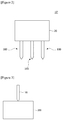
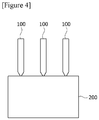
- Figures 3 and 4 are schematic diagrams showing embodiments in which a heat-dissipating material is injected into a first external device (200).
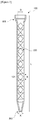
- Figure 5 is a schematic diagram of the static mixer (100) shown in Figure 1 .
- the dispensing apparatus (10, 10') for a heat-dissipating material related to the present invention is an apparatus for injecting a heat-dissipating material including a roomtemperature curing filler into an external device.
- a heat-dissipating material may be injected into an external device (200, 300) through a dispensing apparatus (10).
- the dispensing apparatus (10) comprises a dispensing part (20) and one or more static mixers (100) connected to the dispensing part (20).
- the external device may be a battery module.
- the first external device refers to a first battery module and the second external device refers to a second battery module.
- the first and second battery modules are merely terms that are stated separately in order to explain process units in turn, and have the same structure.
- the mixing and the injection of the heat-dissipating material are performed through static mixers (100).
- the mixing of the heat-dissipating material may be performed in each static mixer (100), and the injection of the heat-dissipating material for one battery module may be performed through a plurality of static mixers (100).
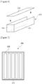
- Figure 6 is a schematic diagram of a module case (210) constituting a battery module
- Figure 7 is a schematic diagram showing a battery module (200)
- Figure 8 is a schematic diagram for explaining injection holes (230) of a module case.
- the battery module (200) comprises a module case (210) and a plurality of battery cells (220) disposed in the module case (210).
- the battery cell (220) may be a pouch-type secondary battery.
- the battery cell (200) may typically comprise an electrode assembly, an electrolyte, and a pouch exterior material. The heat-dissipating material is injected into spaces between the battery cells in the module case and functions to dissipate heat generated in the battery cells (220).
- the module case (210) may have, for example, a cuboidal shape and may have a bottom surface (211), side surfaces (212) and a top surface (213). At this time, one or more injection holes (230) may be formed on the top surface (213). At this time, one static mixer (100) is connected to one injection hole (230), so that the heat-dissipating material flowing out of the static mixer (100) can be injected into the battery module (200) through the injection hole (230).
- the step of injecting a heat-dissipating material may be sequentially performed on a plurality of battery modules.
- the heat-dissipating material may be injected into the second battery module (300).
- the first and second battery modules (200, 300) are transferred by a transfer part (for example, a belt conveyor) and sequentially passed through the dispensing apparatus (100), whereby a heat-dissipating material can be injected.
- the heat-dissipating material may also be injected into one battery module (for example, the first battery module, 200) through one static mixer, and referring to Figure 4 , the heat-dissipating material may be injected into one battery module (for example, the first battery module, 200) through a plurality of static mixers (100).
- the dispensing apparatus (100) for mixing and injecting a heat-dissipating material comprises a dispensing part (20) and one or more static mixers (100) connected to the dispensing part (20).
- the static mixer (100) may be provided interchangeably.
- the heat-dissipating material mixed through the static mixer and injected into a battery module relates to a thermally conductive resin composition.
- the resin composition may comprise a resin component and a thermally conductive filler.
- the dispensing part (20) comprises a first supply cartridge portion (21) and a second supply cartridge portion (22). At this time, the first supply cartridge portion (21) and the second supply cartridge portion (22) are connected to the static mixer (100) individually.
- the first supply cartridge portion (21) supplies a main resin and a thermally conductive filler for forming a resin composition to the static mixer (100) and the second supply cartridge portion (22) supplies a curing agent and a thermally conductive filler to the static mixer (100).
- the static mixer (100) has an inflow part (101) and an outflow part (102).
- the inflow part (101) is provided to be separately connected to the first supply cartridge portion (21) and the second supply cartridge portion (22), and the outflow part (102) is provided to be connected to injection holes (230) provided at the module case (210) of the battery module (200).
- the static mixer (100) comprises a screw part (120) for mixing and transfer.
- the screw part (120) is composed of a plurality of elements (121) and one element (121) forms one stage (B), where the number of elements (121) can be referred to as a number of stages.
- the number of elements (121) of the static mixer (100) may be 5 to 25. If the number of elements (121) is insufficient, the mixing efficiency lowers, which may affect the curing speed, the adhesive force, the insulating property, and the like, or cause reliability problems. Alternatively, if the number of elements (121) is excessively large, a mixer having a small diameter and a long length is used to maintain the same mixer capacity, and thus the process speed is lowered.
- the static mixer (100) has a mixer inner diameter (D) of about 9mm, where the screw part (120) is disposed, a screw part (120) width of 5mm, an outflow part (102) diameter (A) of 3mm, a mixer length (L) of 225mm and a number of stages of 24.
- the first and second supply cartridge portions (21, 22) may each comprise a positive-displacement pump, for supplying a main resin and a curing agent to a static mixer.
- the positive-displacement pump is a pump having a type that a space is provided in a reciprocating portion or a rotating portion, and fluids (for example, a main resin/a curing agent) are placed in the space and simultaneously discharged in turn, which is divided into a reciprocating pump and a rotary pump.
- the first and second supply cartridge portions (21, 22) may each comprise a reciprocating pump or a rotary pump.
- the characteristics of the positive-displacement pump are that the discharge amount fluctuates during operation, but the high pressure is generated and the efficiency is good. Furthermore, even if the pressure is changed, the discharge amount does not change.
- the reciprocating pump is a pump that a fluid is sucked by reciprocating a piston or plunger in a cylinder, compressed at a desired pressure and discharged.
- a manual pump that a discharge valve is installed on a piston
- a single-acting plunger pump which is sucked and discharged whenever a rod-like plunger reciprocates
- a double-acting plunger pump that sucking and discharging are performed every reciprocation of a plunger, and besides, for increasing a flow rate and reducing variation of a discharge amount, there is also a pump in which two or more single-acting ones are connected in parallel.
- the reciprocating pump has a small amount of pumping discharge, but has a simple structure and is suitable for a high lifting height (high-pressure).
- high-pressure high lifting height
- the rotary pump is a pump that a liquid is pumped by rotation of one to three rotors, which is simple in structure and easy to handle.
- the characteristics of the pump are that the fluctuation of the pumping discharge is small, and it is relatively easy to obtain a high pressure and is suitable for transporting a liquid having a high viscosity such as oil.
- a typical example thereof includes a vane pump, a gear pump, a screw pump and the like.
- the present invention relates to a method for determining a dispensing apparatus for a heat-dissipating material.
- the method for determining a dispensing apparatus for a heat-dissipating material comprises steps of detecting an internal material of a dispensing apparatus from a heat-dissipating material discharged from the dispensing apparatus and determining suitability of the dispensing apparatus based on the detected amount of the internal material.
- the heat-dissipating material flowing out of the dispensing apparatus means a heat-dissipating material discharged from the static mixer.
- an ICP analysis method can be used as the method of detecting the internal material.
- the used instrument may be ICP-OES (Optima 8300DV), and 0.2 g of the heat-dissipating material discharged from the static mixer may be treated with nitric acid/hydrogen peroxide and then filtered using a 0.45 ⁇ m PTFE syringe and analyzed by ICP-OES.
- the dispensing apparatus may be determined to be suitable.
- the internal material may comprise iron (Fe).
- the dispensing apparatus may be determined to be suitable.
- the dispensing apparatus may be determined to be suitable.
- the heat-dissipating material may comprise a resin component of urethane series and a thermally conductive filler.
- the heat-dissipating material may comprise a filler having a Mohs hardness of 8 or more.
- the filler having a Mohs hardness of 8 or more may be 80 wt% or more of the entire filler.
- the filler weight may be 70 wt% or more of the entire paste weight.
- the heat-dissipating material comprises a filler having a Mohs hardness of 8 or more, and it is preferred in the heat-dissipating material that the filler having a Mohs hardness of 8 or more is 80 wt% or more of the entire filler.
- the first and second supply cartridge portions may be configured as a gear pump type or a plunger pump type.
- the heat-dissipating material relates to a thermally conductive resin composition.
- the resin composition may comprise a resin component and a thermally conductive filler.
- the resin composition may be an adhesive composition, for example, a composition capable of forming an adhesive through a curing reaction or the like.
- a resin composition may be a solvent type resin composition, a water-based resin composition, or a solventless-type resin composition.
- the resin composition may be prepared by compounding a thermally conductive filler, which is described below, to a resin composition capable of forming a known acrylic adhesive, epoxy adhesive, urethane adhesive, olefin adhesive, EVA (ethylene vinyl acetate) adhesive or silicone adhesive.
- resin component is generally used as a meaning to include components known as resins as well as components that can be converted into resins through a curing reaction or a polymerization reaction.
- an adhesive resin or a precursor capable of forming an adhesive resin can be applied as the resin component.
- a resin component includes an acrylic resin, an epoxy resin, a urethane resin, an olefin resin, an EVA (ethylene vinyl acetate) resin or a silicone resin, and the like, or a precursor such as a polyol or an isocyanate compound, and the like, but is not limited thereto.
- the resin composition may comprise a thermally conductive filler together with the resin component.
- thermally conductive filler means a material having a thermal conductivity of about 1 W/mK or more, about 5 W/mK or more, about 10 W/mK or more, or about 15 W/mK or more.
- the thermal conductivity of the thermally conductive filler may be about 400 W/mK or less, about 350 W/mK or less, or about 300 W/mK or less.
- the kind of thermally conductive filler is not particularly limited, but ceramic fillers may be applied in consideration of insulation and the like.
- ceramic particles such as alumina, AlN (aluminum nitride), BN (boron nitride), silicon nitride, SiC or BeO may be used. If insulation properties may be secured, application of carbon fillers such as graphite may also be considered.
- the resin composition may comprise about 600 parts by weight or more of the thermally conductive filler relative to 100 parts by weight of the resin component.
- the ratio of the filler may be 650 parts by weight or more, or 700 parts by weight or more, relative to 100 parts by weight of the resin component.
- the ratio may be about 2,000 parts by weight or less, about 1,500 parts by weight or less, or about 1,100 parts by weight or less, relative to 100 parts by weight of the resin component.
- Within the ratio range of the filler it is possible to secure desired physical properties such as thermal conductivity and insulation.
- the viscosity of the resin composition is greatly increased and accordingly, the handling property is lowered, and even after the resin material is formed, it contains bubbles or voids, so that the thermal conductivity may be deteriorated.
- a filler having at least three different diameters may be applied to the resin composition at a predetermined ratio.
- the shape of the filler is not particularly limited, which may be selected in consideration of viscosity and thixotropy of the resin composition, possibility of settling in the composition, the target thermal resistance or thermal conductivity, insulation, a filling effect or dispersibility, and the like.
- a spherical filler considering the amount to be filled, it is advantageous to use a spherical filler, but in consideration of formation of a network, conductivity, thixotropy and the like, a non-spherical filler, for example, a filler having a shape such as a needle shape or a plate shape can also be used.
- the resin composition basically comprises the above components, that is, the resin component and the thermally conductive filler, and if necessary, it may also comprise other components.
- the resin composition may further comprise a viscosity control agent, such as a thixotropic agent, a diluent, a dispersant, a surface treatment agent or a coupling agent, for control of viscosity, for example, for increasing or decreasing viscosity, or for control of viscosity according to shear force.
- a viscosity control agent such as a thixotropic agent, a diluent, a dispersant, a surface treatment agent or a coupling agent, for control of viscosity, for example, for increasing or decreasing viscosity, or for control of viscosity according to shear force.
- the thixotropic agent can control the viscosity according to the shear force of the resin composition so that the manufacturing process of the battery module can be effectively performed.
- the usable thixotropic agent can be exemplified by fumed silica and the like.
- the diluent or dispersant is usually used for lowering the viscosity of the resin composition, and any of various kinds known in the art can be used without limitation as long as it can exhibit the above action.
- the surface treating agent is used for surface treatment of the filler introduced into the resin composition, and any of various kinds known in the art can be used without limitation as long as it can exhibit the above action.
- the coupling agent may be used, for example, to improve the dispersibility of the thermally conductive filler such as alumina, and any of various kinds known in the art may be used without limitation as long as it can exhibit the above action.
- the resin composition may further comprise a flame retardant or a flame retardant auxiliary agent, and the like.
- a resin composition can form a flame retardant resin composition.
- various known flame retardants can be applied without particular limitation, and for example, a solid filler-shaped flame retardant or a liquid flame retardant, and the like can be applied.
- the flame retardant includes, for example, an organic flame retardant such as melamine cyanurate, or an inorganic flame retardant such as magnesium hydroxide, and the like, but is not limited thereto.
- a liquid type flame retardant material (TEP, triethyl phosphate or TCPP, tris(1,3-chloro-2-propyl) phosphate, etc.) may also be used.
- a silane coupling agent capable of acting as a flame retardant synergist may also be added.
- the suitability of the dispensing apparatus can be determined by detecting the internal material of the dispensing apparatus from the heat-dissipating material discharged from the dispensing apparatus.
Landscapes
- Engineering & Computer Science (AREA)
- Mechanical Engineering (AREA)
- General Engineering & Computer Science (AREA)
- Processing And Handling Of Plastics And Other Materials For Molding In General (AREA)
- Cooling Or The Like Of Semiconductors Or Solid State Devices (AREA)
- Accessories For Mixers (AREA)
- Secondary Cells (AREA)
Applications Claiming Priority (2)
| Application Number | Priority Date | Filing Date | Title |
|---|---|---|---|
| KR20170105934 | 2017-08-22 | ||
| PCT/KR2018/009638 WO2019039852A1 (ko) | 2017-08-22 | 2018-08-22 | 방열 소재 디스펜싱 장치의 결정방법 |
Publications (3)
| Publication Number | Publication Date |
|---|---|
| EP3663582A1 true EP3663582A1 (de) | 2020-06-10 |
| EP3663582A4 EP3663582A4 (de) | 2020-08-26 |
| EP3663582B1 EP3663582B1 (de) | 2022-04-06 |
Family
ID=65760425
Family Applications (1)
| Application Number | Title | Priority Date | Filing Date |
|---|---|---|---|
| EP18848936.3A Active EP3663582B1 (de) | 2017-08-22 | 2018-08-22 | Verfahren zur bestimmung der geeignetheit einer vorrichtung zur abgabe eines wärmeableitungsmaterials |
Country Status (5)
| Country | Link |
|---|---|
| US (1) | US11598325B2 (de) |
| EP (1) | EP3663582B1 (de) |
| JP (1) | JP6976420B2 (de) |
| KR (1) | KR102118366B1 (de) |
| CN (1) | CN111051698B (de) |
Cited By (1)
| Publication number | Priority date | Publication date | Assignee | Title |
|---|---|---|---|---|
| EP3662992A4 (de) * | 2017-08-22 | 2020-08-12 | LG Chem, Ltd. | Verfahren zum mischen von wärmeableitmaterialkomponenten |
Families Citing this family (4)
| Publication number | Priority date | Publication date | Assignee | Title |
|---|---|---|---|---|
| EP4006090A4 (de) * | 2019-08-19 | 2022-09-07 | LG Chem, Ltd. | Harzzusammensetzung |
| EP4006089A4 (de) * | 2019-08-19 | 2022-08-31 | LG Chem, Ltd. | Harzzusammensetzung |
| KR20220119031A (ko) * | 2019-12-19 | 2022-08-26 | 헨켈 아게 운트 코. 카게아아 | 반응성 희석제를 갖는 실리콘 무함유 열 계면 물질 |
| CN114404799B (zh) * | 2022-01-25 | 2023-03-21 | 郭政 | 一种往复式磁力泵体、泵组及模拟心脏 |
Family Cites Families (28)
| Publication number | Priority date | Publication date | Assignee | Title |
|---|---|---|---|---|
| US4366918A (en) * | 1979-04-20 | 1983-01-04 | Naka Seiki Company Limited | Variable ratio metering, mixing and dispensing apparatus |
| US4492461A (en) * | 1981-03-19 | 1985-01-08 | Jones David G | Wear analysis equipment |
| DE3522922A1 (de) * | 1985-06-27 | 1987-01-08 | Hedrich Vakuumanlagen Wilhelm | Giessanlage fuer die verarbeitung von giessharz |
| US4869954A (en) * | 1987-09-10 | 1989-09-26 | Chomerics, Inc. | Thermally conductive materials |
| CA1331395C (en) | 1989-02-01 | 1994-08-09 | James R. Kleisle | Wear indicator for material transfer systems |
| JP3116625B2 (ja) * | 1993-02-04 | 2000-12-11 | 東洋インキ製造株式会社 | 金属フタロシアニン顔料の製造法 |
| US6386237B1 (en) | 1999-04-12 | 2002-05-14 | The Goodyear Tire & Rubber Company | Abrasive material transport hose with wear detecting sensors |
| JP2001163989A (ja) | 1999-12-13 | 2001-06-19 | Toyobo Co Ltd | ポリ燐酸溶液から成形体を製造する方法 |
| US7208192B2 (en) * | 2002-05-31 | 2007-04-24 | Parker-Hannifin Corporation | Thermally or electrically-conductive form-in-place gap filter |
| JP2006328352A (ja) | 2005-04-28 | 2006-12-07 | Idemitsu Kosan Co Ltd | 絶縁性熱伝導性樹脂組成物及び成形品並びにその製造方法 |
| JP4728731B2 (ja) | 2005-08-01 | 2011-07-20 | 株式会社Gns | 二液硬化型材料の供給方法 |
| JP5227801B2 (ja) | 2006-10-31 | 2013-07-03 | 電気化学工業株式会社 | アルミナ粉末及びその製造方法、並びにその用途 |
| US20090107921A1 (en) | 2007-10-26 | 2009-04-30 | Honeywell International Inc. | Chemical treatment system and method |
| JP2010070583A (ja) * | 2008-09-16 | 2010-04-02 | Sekisui Chem Co Ltd | 基板穴埋め用熱伝導性ペースト組成物、及び、プリント配線基板 |
| CN101393108B (zh) * | 2008-10-10 | 2010-09-08 | 南京航空航天大学 | 油液磨粒在线监测方法及系统 |
| JP2010155942A (ja) * | 2008-12-29 | 2010-07-15 | Sanyo Chem Ind Ltd | 切削加工用模型素材形成性組成物 |
| US8659287B2 (en) * | 2009-03-12 | 2014-02-25 | Ihi Corporation | Hard particle concentration detecting method |
| KR101580451B1 (ko) * | 2009-04-23 | 2015-12-28 | 주식회사 동진쎄미켐 | 연속식 혼합 장치를 이용한 화학 조성물 제조 장치 |
| JP5247637B2 (ja) * | 2009-09-02 | 2013-07-24 | サンユレック株式会社 | 攪拌混合管及び攪拌混合装置 |
| US8196464B2 (en) * | 2010-01-05 | 2012-06-12 | The Raymond Corporation | Apparatus and method for monitoring a hydraulic pump on a material handling vehicle |
| JP2011179468A (ja) | 2010-03-03 | 2011-09-15 | Dow Corning Toray Co Ltd | 高粘性流体用ディスペンサー |
| ES2738511T3 (es) * | 2011-04-07 | 2020-01-23 | Circor Pumps North America Llc | Sistema y método para monitorizar el desgaste de un forro de bomba |
| EP2943714A4 (de) * | 2013-01-09 | 2016-08-17 | Cidra Corporate Services Inc | Intelligentes rohrkonzept auf basis eines eingebetteten taggant-sensors und/oder farbcodierter elemente zur überwachung eines auskleidungsverschleisses in ausgekleideten rohrleitungen einschliesslich mit urethan ausgekleideter rohrleitungen |
| JP6352604B2 (ja) * | 2013-08-20 | 2018-07-04 | ヘイシンテクノベルク株式会社 | 回転容積型ポンプ用摺動部材、及び回転容積型ポンプ運転状態検知システム |
| JP2015131909A (ja) * | 2014-01-14 | 2015-07-23 | 日油株式会社 | 熱可塑性エラストマー |
| CN108139665B (zh) | 2015-12-22 | 2022-07-05 | 卡本有限公司 | 用于用双重固化树脂的增材制造的双重前体树脂系统 |
| EP3211418A1 (de) * | 2016-02-23 | 2017-08-30 | C.C. Jensen A/S | Beurteilung des flüssigkeitszustands für ein multimodal operierendes system |
| JP6973875B2 (ja) | 2017-08-22 | 2021-12-01 | エルジー・ケム・リミテッド | 放熱素材の混合方法 |
-
2018
- 2018-08-22 EP EP18848936.3A patent/EP3663582B1/de active Active
- 2018-08-22 US US16/641,120 patent/US11598325B2/en active Active
- 2018-08-22 KR KR1020180097734A patent/KR102118366B1/ko active Active
- 2018-08-22 CN CN201880053601.5A patent/CN111051698B/zh active Active
- 2018-08-22 JP JP2020511247A patent/JP6976420B2/ja active Active
Cited By (2)
| Publication number | Priority date | Publication date | Assignee | Title |
|---|---|---|---|---|
| EP3662992A4 (de) * | 2017-08-22 | 2020-08-12 | LG Chem, Ltd. | Verfahren zum mischen von wärmeableitmaterialkomponenten |
| US11185832B2 (en) * | 2017-08-22 | 2021-11-30 | Lg Chem, Ltd. | Method for mixing heat-dissipating material |
Also Published As
| Publication number | Publication date |
|---|---|
| JP6976420B2 (ja) | 2021-12-08 |
| CN111051698A (zh) | 2020-04-21 |
| KR102118366B1 (ko) | 2020-06-04 |
| EP3663582A4 (de) | 2020-08-26 |
| KR20190021182A (ko) | 2019-03-05 |
| EP3663582B1 (de) | 2022-04-06 |
| JP2020531265A (ja) | 2020-11-05 |
| US20200208618A1 (en) | 2020-07-02 |
| US11598325B2 (en) | 2023-03-07 |
| CN111051698B (zh) | 2022-04-22 |
Similar Documents
| Publication | Publication Date | Title |
|---|---|---|
| EP3663582A1 (de) | Verfahren zur bestimmung einer vorrichtung zur abgabe eines wärmeableitungsmaterials | |
| EP3662992A2 (de) | Verfahren zum mischen von wärmeableitmaterialkomponenten | |
| KR102934539B1 (ko) | 고온 프로세스들을 위한 정전 척 어셈블리 | |
| CN111377713B (zh) | 一种复相荧光陶瓷及其制备方法 | |
| JP6293362B2 (ja) | 加熱と冷却が可能な等方圧プレス装置、及びそれを用いたチップ部品の製造方法 | |
| JP7282950B2 (ja) | 電気回路装置の放熱構造 | |
| US20120161554A1 (en) | cooling system for a high density power motor, in particular an axial-flux motor | |
| US20130187063A1 (en) | Micro-channel-cooled high heat load light emitting device | |
| KR20180124915A (ko) | 세라믹 수지 복합체 | |
| EP4169978A1 (de) | Silikonzusammensetzung und wärmeleitendes gehärtetes silikonprodukt mit hoher wärmeleitfähigkeit | |
| US9930774B2 (en) | Flexible-to-rigid tubing | |
| DE102013012143A1 (de) | Kühlmittelpumpe für ein Kraftfahrzeug zur Kühlung einer Brennkraftmaschine oder einer alternativen Antriebsvorrichtung | |
| JP4804343B2 (ja) | セラミックシートの製造方法 | |
| KR102403680B1 (ko) | 다양한 크기의 세라믹 비드를 포함하는 폴리실록산 복합체 및 이의 제조방법 | |
| CN101351755A (zh) | 可分配固化树脂 | |
| CN215512709U (zh) | 一种定向高导热石墨基热界面复合材料结构 | |
| CN1166535A (zh) | 密封装置 | |
| KR101544190B1 (ko) | 엘이디 조명등용 방열시트 및 그 제조방법 | |
| WO2019039852A1 (ko) | 방열 소재 디스펜싱 장치의 결정방법 | |
| US20070048148A1 (en) | Pump and liquid supply apparatus having the pump | |
| WO2019039855A2 (ko) | 방열 소재의 혼합 방법 | |
| KR102576371B1 (ko) | 스트론튬 계열 형광소재를 사용한 무용제 에폭시 수지 기반의 방열 조성물 | |
| US7445727B2 (en) | Thermal interface material compound and method of fabricating the same | |
| KR20230164643A (ko) | 냉각판 및 반도체 제조 장치용 부재 | |
| KR20160032613A (ko) | 다이 접착 페이스트 및 그 제조방법 |
Legal Events
| Date | Code | Title | Description |
|---|---|---|---|
| STAA | Information on the status of an ep patent application or granted ep patent |
Free format text: STATUS: THE INTERNATIONAL PUBLICATION HAS BEEN MADE |
|
| PUAI | Public reference made under article 153(3) epc to a published international application that has entered the european phase |
Free format text: ORIGINAL CODE: 0009012 |
|
| STAA | Information on the status of an ep patent application or granted ep patent |
Free format text: STATUS: REQUEST FOR EXAMINATION WAS MADE |
|
| 17P | Request for examination filed |
Effective date: 20200302 |
|
| AK | Designated contracting states |
Kind code of ref document: A1 Designated state(s): AL AT BE BG CH CY CZ DE DK EE ES FI FR GB GR HR HU IE IS IT LI LT LU LV MC MK MT NL NO PL PT RO RS SE SI SK SM TR |
|
| AX | Request for extension of the european patent |
Extension state: BA ME |
|
| A4 | Supplementary search report drawn up and despatched |
Effective date: 20200723 |
|
| RIC1 | Information provided on ipc code assigned before grant |
Ipc: B29B 7/32 20060101ALI20200718BHEP Ipc: F04B 51/00 20060101ALI20200718BHEP Ipc: B29B 7/90 20060101ALI20200718BHEP Ipc: F04B 53/08 20060101ALI20200718BHEP Ipc: F04C 2/08 20060101ALI20200718BHEP Ipc: F04B 19/22 20060101ALI20200718BHEP Ipc: F04C 14/28 20060101ALI20200718BHEP Ipc: B29B 7/72 20060101AFI20200718BHEP |
|
| DAV | Request for validation of the european patent (deleted) | ||
| DAX | Request for extension of the european patent (deleted) | ||
| STAA | Information on the status of an ep patent application or granted ep patent |
Free format text: STATUS: EXAMINATION IS IN PROGRESS |
|
| 17Q | First examination report despatched |
Effective date: 20210219 |
|
| REG | Reference to a national code |
Ref country code: DE Ref legal event code: R079 Ref document number: 602018033574 Country of ref document: DE Free format text: PREVIOUS MAIN CLASS: F04C0014280000 Ipc: B29B0007720000 |
|
| RIC1 | Information provided on ipc code assigned before grant |
Ipc: F04C 13/00 20060101ALN20211006BHEP Ipc: F04B 53/08 20060101ALI20211006BHEP Ipc: F04B 51/00 20060101ALI20211006BHEP Ipc: F04B 19/22 20060101ALI20211006BHEP Ipc: B29B 7/90 20060101ALI20211006BHEP Ipc: B29B 7/32 20060101ALI20211006BHEP Ipc: B29B 7/72 20060101AFI20211006BHEP |
|
| GRAP | Despatch of communication of intention to grant a patent |
Free format text: ORIGINAL CODE: EPIDOSNIGR1 |
|
| STAA | Information on the status of an ep patent application or granted ep patent |
Free format text: STATUS: GRANT OF PATENT IS INTENDED |
|
| INTG | Intention to grant announced |
Effective date: 20211125 |
|
| GRAS | Grant fee paid |
Free format text: ORIGINAL CODE: EPIDOSNIGR3 |
|
| GRAA | (expected) grant |
Free format text: ORIGINAL CODE: 0009210 |
|
| STAA | Information on the status of an ep patent application or granted ep patent |
Free format text: STATUS: THE PATENT HAS BEEN GRANTED |
|
| AK | Designated contracting states |
Kind code of ref document: B1 Designated state(s): AL AT BE BG CH CY CZ DE DK EE ES FI FR GB GR HR HU IE IS IT LI LT LU LV MC MK MT NL NO PL PT RO RS SE SI SK SM TR |
|
| REG | Reference to a national code |
Ref country code: GB Ref legal event code: FG4D |
|
| REG | Reference to a national code |
Ref country code: CH Ref legal event code: EP |
|
| REG | Reference to a national code |
Ref country code: AT Ref legal event code: REF Ref document number: 1480907 Country of ref document: AT Kind code of ref document: T Effective date: 20220415 |
|
| REG | Reference to a national code |
Ref country code: DE Ref legal event code: R096 Ref document number: 602018033574 Country of ref document: DE |
|
| REG | Reference to a national code |
Ref country code: IE Ref legal event code: FG4D |
|
| REG | Reference to a national code |
Ref country code: LT Ref legal event code: MG9D |
|
| REG | Reference to a national code |
Ref country code: NL Ref legal event code: MP Effective date: 20220406 |
|
| REG | Reference to a national code |
Ref country code: AT Ref legal event code: MK05 Ref document number: 1480907 Country of ref document: AT Kind code of ref document: T Effective date: 20220406 |
|
| PG25 | Lapsed in a contracting state [announced via postgrant information from national office to epo] |
Ref country code: NL Free format text: LAPSE BECAUSE OF FAILURE TO SUBMIT A TRANSLATION OF THE DESCRIPTION OR TO PAY THE FEE WITHIN THE PRESCRIBED TIME-LIMIT Effective date: 20220406 |
|
| PG25 | Lapsed in a contracting state [announced via postgrant information from national office to epo] |
Ref country code: SE Free format text: LAPSE BECAUSE OF FAILURE TO SUBMIT A TRANSLATION OF THE DESCRIPTION OR TO PAY THE FEE WITHIN THE PRESCRIBED TIME-LIMIT Effective date: 20220406 Ref country code: PT Free format text: LAPSE BECAUSE OF FAILURE TO SUBMIT A TRANSLATION OF THE DESCRIPTION OR TO PAY THE FEE WITHIN THE PRESCRIBED TIME-LIMIT Effective date: 20220808 Ref country code: NO Free format text: LAPSE BECAUSE OF FAILURE TO SUBMIT A TRANSLATION OF THE DESCRIPTION OR TO PAY THE FEE WITHIN THE PRESCRIBED TIME-LIMIT Effective date: 20220706 Ref country code: LT Free format text: LAPSE BECAUSE OF FAILURE TO SUBMIT A TRANSLATION OF THE DESCRIPTION OR TO PAY THE FEE WITHIN THE PRESCRIBED TIME-LIMIT Effective date: 20220406 Ref country code: HR Free format text: LAPSE BECAUSE OF FAILURE TO SUBMIT A TRANSLATION OF THE DESCRIPTION OR TO PAY THE FEE WITHIN THE PRESCRIBED TIME-LIMIT Effective date: 20220406 Ref country code: GR Free format text: LAPSE BECAUSE OF FAILURE TO SUBMIT A TRANSLATION OF THE DESCRIPTION OR TO PAY THE FEE WITHIN THE PRESCRIBED TIME-LIMIT Effective date: 20220707 Ref country code: FI Free format text: LAPSE BECAUSE OF FAILURE TO SUBMIT A TRANSLATION OF THE DESCRIPTION OR TO PAY THE FEE WITHIN THE PRESCRIBED TIME-LIMIT Effective date: 20220406 Ref country code: ES Free format text: LAPSE BECAUSE OF FAILURE TO SUBMIT A TRANSLATION OF THE DESCRIPTION OR TO PAY THE FEE WITHIN THE PRESCRIBED TIME-LIMIT Effective date: 20220406 Ref country code: BG Free format text: LAPSE BECAUSE OF FAILURE TO SUBMIT A TRANSLATION OF THE DESCRIPTION OR TO PAY THE FEE WITHIN THE PRESCRIBED TIME-LIMIT Effective date: 20220706 Ref country code: AT Free format text: LAPSE BECAUSE OF FAILURE TO SUBMIT A TRANSLATION OF THE DESCRIPTION OR TO PAY THE FEE WITHIN THE PRESCRIBED TIME-LIMIT Effective date: 20220406 |
|
| PG25 | Lapsed in a contracting state [announced via postgrant information from national office to epo] |
Ref country code: RS Free format text: LAPSE BECAUSE OF FAILURE TO SUBMIT A TRANSLATION OF THE DESCRIPTION OR TO PAY THE FEE WITHIN THE PRESCRIBED TIME-LIMIT Effective date: 20220406 Ref country code: PL Free format text: LAPSE BECAUSE OF FAILURE TO SUBMIT A TRANSLATION OF THE DESCRIPTION OR TO PAY THE FEE WITHIN THE PRESCRIBED TIME-LIMIT Effective date: 20220406 Ref country code: LV Free format text: LAPSE BECAUSE OF FAILURE TO SUBMIT A TRANSLATION OF THE DESCRIPTION OR TO PAY THE FEE WITHIN THE PRESCRIBED TIME-LIMIT Effective date: 20220406 Ref country code: IS Free format text: LAPSE BECAUSE OF FAILURE TO SUBMIT A TRANSLATION OF THE DESCRIPTION OR TO PAY THE FEE WITHIN THE PRESCRIBED TIME-LIMIT Effective date: 20220806 |
|
| REG | Reference to a national code |
Ref country code: DE Ref legal event code: R097 Ref document number: 602018033574 Country of ref document: DE |
|
| PG25 | Lapsed in a contracting state [announced via postgrant information from national office to epo] |
Ref country code: SM Free format text: LAPSE BECAUSE OF FAILURE TO SUBMIT A TRANSLATION OF THE DESCRIPTION OR TO PAY THE FEE WITHIN THE PRESCRIBED TIME-LIMIT Effective date: 20220406 Ref country code: SK Free format text: LAPSE BECAUSE OF FAILURE TO SUBMIT A TRANSLATION OF THE DESCRIPTION OR TO PAY THE FEE WITHIN THE PRESCRIBED TIME-LIMIT Effective date: 20220406 Ref country code: RO Free format text: LAPSE BECAUSE OF FAILURE TO SUBMIT A TRANSLATION OF THE DESCRIPTION OR TO PAY THE FEE WITHIN THE PRESCRIBED TIME-LIMIT Effective date: 20220406 Ref country code: EE Free format text: LAPSE BECAUSE OF FAILURE TO SUBMIT A TRANSLATION OF THE DESCRIPTION OR TO PAY THE FEE WITHIN THE PRESCRIBED TIME-LIMIT Effective date: 20220406 Ref country code: DK Free format text: LAPSE BECAUSE OF FAILURE TO SUBMIT A TRANSLATION OF THE DESCRIPTION OR TO PAY THE FEE WITHIN THE PRESCRIBED TIME-LIMIT Effective date: 20220406 Ref country code: CZ Free format text: LAPSE BECAUSE OF FAILURE TO SUBMIT A TRANSLATION OF THE DESCRIPTION OR TO PAY THE FEE WITHIN THE PRESCRIBED TIME-LIMIT Effective date: 20220406 |
|
| PLBE | No opposition filed within time limit |
Free format text: ORIGINAL CODE: 0009261 |
|
| STAA | Information on the status of an ep patent application or granted ep patent |
Free format text: STATUS: NO OPPOSITION FILED WITHIN TIME LIMIT |
|
| 26N | No opposition filed |
Effective date: 20230110 |
|
| PG25 | Lapsed in a contracting state [announced via postgrant information from national office to epo] |
Ref country code: MC Free format text: LAPSE BECAUSE OF FAILURE TO SUBMIT A TRANSLATION OF THE DESCRIPTION OR TO PAY THE FEE WITHIN THE PRESCRIBED TIME-LIMIT Effective date: 20220406 Ref country code: AL Free format text: LAPSE BECAUSE OF FAILURE TO SUBMIT A TRANSLATION OF THE DESCRIPTION OR TO PAY THE FEE WITHIN THE PRESCRIBED TIME-LIMIT Effective date: 20220406 |
|
| REG | Reference to a national code |
Ref country code: CH Ref legal event code: PL |
|
| PG25 | Lapsed in a contracting state [announced via postgrant information from national office to epo] |
Ref country code: LU Free format text: LAPSE BECAUSE OF NON-PAYMENT OF DUE FEES Effective date: 20220822 Ref country code: LI Free format text: LAPSE BECAUSE OF NON-PAYMENT OF DUE FEES Effective date: 20220831 Ref country code: CH Free format text: LAPSE BECAUSE OF NON-PAYMENT OF DUE FEES Effective date: 20220831 |
|
| REG | Reference to a national code |
Ref country code: BE Ref legal event code: MM Effective date: 20220831 |
|
| PG25 | Lapsed in a contracting state [announced via postgrant information from national office to epo] |
Ref country code: SI Free format text: LAPSE BECAUSE OF FAILURE TO SUBMIT A TRANSLATION OF THE DESCRIPTION OR TO PAY THE FEE WITHIN THE PRESCRIBED TIME-LIMIT Effective date: 20220406 |
|
| PG25 | Lapsed in a contracting state [announced via postgrant information from national office to epo] |
Ref country code: IE Free format text: LAPSE BECAUSE OF NON-PAYMENT OF DUE FEES Effective date: 20220822 |
|
| PG25 | Lapsed in a contracting state [announced via postgrant information from national office to epo] |
Ref country code: BE Free format text: LAPSE BECAUSE OF NON-PAYMENT OF DUE FEES Effective date: 20220831 |
|
| PG25 | Lapsed in a contracting state [announced via postgrant information from national office to epo] |
Ref country code: IT Free format text: LAPSE BECAUSE OF FAILURE TO SUBMIT A TRANSLATION OF THE DESCRIPTION OR TO PAY THE FEE WITHIN THE PRESCRIBED TIME-LIMIT Effective date: 20220406 |
|
| PG25 | Lapsed in a contracting state [announced via postgrant information from national office to epo] |
Ref country code: CY Free format text: LAPSE BECAUSE OF FAILURE TO SUBMIT A TRANSLATION OF THE DESCRIPTION OR TO PAY THE FEE WITHIN THE PRESCRIBED TIME-LIMIT Effective date: 20220406 |
|
| PG25 | Lapsed in a contracting state [announced via postgrant information from national office to epo] |
Ref country code: MK Free format text: LAPSE BECAUSE OF FAILURE TO SUBMIT A TRANSLATION OF THE DESCRIPTION OR TO PAY THE FEE WITHIN THE PRESCRIBED TIME-LIMIT Effective date: 20220406 Ref country code: HU Free format text: LAPSE BECAUSE OF FAILURE TO SUBMIT A TRANSLATION OF THE DESCRIPTION OR TO PAY THE FEE WITHIN THE PRESCRIBED TIME-LIMIT; INVALID AB INITIO Effective date: 20180822 |
|
| PG25 | Lapsed in a contracting state [announced via postgrant information from national office to epo] |
Ref country code: MT Free format text: LAPSE BECAUSE OF FAILURE TO SUBMIT A TRANSLATION OF THE DESCRIPTION OR TO PAY THE FEE WITHIN THE PRESCRIBED TIME-LIMIT Effective date: 20220406 |
|
| PG25 | Lapsed in a contracting state [announced via postgrant information from national office to epo] |
Ref country code: BG Free format text: LAPSE BECAUSE OF FAILURE TO SUBMIT A TRANSLATION OF THE DESCRIPTION OR TO PAY THE FEE WITHIN THE PRESCRIBED TIME-LIMIT Effective date: 20220406 |
|
| PG25 | Lapsed in a contracting state [announced via postgrant information from national office to epo] |
Ref country code: BG Free format text: LAPSE BECAUSE OF FAILURE TO SUBMIT A TRANSLATION OF THE DESCRIPTION OR TO PAY THE FEE WITHIN THE PRESCRIBED TIME-LIMIT Effective date: 20220406 |
|
| PGFP | Annual fee paid to national office [announced via postgrant information from national office to epo] |
Ref country code: DE Payment date: 20250721 Year of fee payment: 8 |
|
| PGFP | Annual fee paid to national office [announced via postgrant information from national office to epo] |
Ref country code: GB Payment date: 20250722 Year of fee payment: 8 |
|
| PGFP | Annual fee paid to national office [announced via postgrant information from national office to epo] |
Ref country code: FR Payment date: 20250725 Year of fee payment: 8 |
|
| PG25 | Lapsed in a contracting state [announced via postgrant information from national office to epo] |
Ref country code: TR Free format text: LAPSE BECAUSE OF FAILURE TO SUBMIT A TRANSLATION OF THE DESCRIPTION OR TO PAY THE FEE WITHIN THE PRESCRIBED TIME-LIMIT Effective date: 20220406 |