EP3663585A1 - Vakuumpumpe mit filterelement - Google Patents
Vakuumpumpe mit filterelement Download PDFInfo
- Publication number
- EP3663585A1 EP3663585A1 EP20155484.7A EP20155484A EP3663585A1 EP 3663585 A1 EP3663585 A1 EP 3663585A1 EP 20155484 A EP20155484 A EP 20155484A EP 3663585 A1 EP3663585 A1 EP 3663585A1
- Authority
- EP
- European Patent Office
- Prior art keywords
- exhaust cover
- vacuum pump
- filter element
- housing
- cartridge
- Prior art date
- Legal status (The legal status is an assumption and is not a legal conclusion. Google has not performed a legal analysis and makes no representation as to the accuracy of the status listed.)
- Granted
Links
Images


Classifications
-
- F—MECHANICAL ENGINEERING; LIGHTING; HEATING; WEAPONS; BLASTING
- F04—POSITIVE - DISPLACEMENT MACHINES FOR LIQUIDS; PUMPS FOR LIQUIDS OR ELASTIC FLUIDS
- F04C—ROTARY-PISTON, OR OSCILLATING-PISTON, POSITIVE-DISPLACEMENT MACHINES FOR LIQUIDS; ROTARY-PISTON, OR OSCILLATING-PISTON, POSITIVE-DISPLACEMENT PUMPS
- F04C25/00—Adaptations of pumps for special use of pumps for elastic fluids
- F04C25/02—Adaptations of pumps for special use of pumps for elastic fluids for producing high vacuum
-
- B—PERFORMING OPERATIONS; TRANSPORTING
- B01—PHYSICAL OR CHEMICAL PROCESSES OR APPARATUS IN GENERAL
- B01D—SEPARATION
- B01D46/00—Filters or filtering processes specially modified for separating dispersed particles from gases or vapours
- B01D46/0039—Filters or filtering processes specially modified for separating dispersed particles from gases or vapours with flow guiding by feed or discharge devices
- B01D46/0041—Filters or filtering processes specially modified for separating dispersed particles from gases or vapours with flow guiding by feed or discharge devices for feeding
-
- B—PERFORMING OPERATIONS; TRANSPORTING
- B01—PHYSICAL OR CHEMICAL PROCESSES OR APPARATUS IN GENERAL
- B01D—SEPARATION
- B01D46/00—Filters or filtering processes specially modified for separating dispersed particles from gases or vapours
- B01D46/0039—Filters or filtering processes specially modified for separating dispersed particles from gases or vapours with flow guiding by feed or discharge devices
- B01D46/0047—Filters or filtering processes specially modified for separating dispersed particles from gases or vapours with flow guiding by feed or discharge devices for discharging the filtered gas
-
- B—PERFORMING OPERATIONS; TRANSPORTING
- B01—PHYSICAL OR CHEMICAL PROCESSES OR APPARATUS IN GENERAL
- B01D—SEPARATION
- B01D46/00—Filters or filtering processes specially modified for separating dispersed particles from gases or vapours
- B01D46/24—Particle separators, e.g. dust precipitators, using rigid hollow filter bodies
- B01D46/2403—Particle separators, e.g. dust precipitators, using rigid hollow filter bodies characterised by the physical shape or structure of the filtering element
- B01D46/2411—Filter cartridges
- B01D46/2414—End caps including additional functions or special forms
-
- B—PERFORMING OPERATIONS; TRANSPORTING
- B01—PHYSICAL OR CHEMICAL PROCESSES OR APPARATUS IN GENERAL
- B01D—SEPARATION
- B01D46/00—Filters or filtering processes specially modified for separating dispersed particles from gases or vapours
- B01D46/42—Auxiliary equipment or operation thereof
- B01D46/4236—Reducing noise or vibration emissions
-
- F—MECHANICAL ENGINEERING; LIGHTING; HEATING; WEAPONS; BLASTING
- F04—POSITIVE - DISPLACEMENT MACHINES FOR LIQUIDS; PUMPS FOR LIQUIDS OR ELASTIC FLUIDS
- F04C—ROTARY-PISTON, OR OSCILLATING-PISTON, POSITIVE-DISPLACEMENT MACHINES FOR LIQUIDS; ROTARY-PISTON, OR OSCILLATING-PISTON, POSITIVE-DISPLACEMENT PUMPS
- F04C18/00—Rotary-piston pumps specially adapted for elastic fluids
- F04C18/30—Rotary-piston pumps specially adapted for elastic fluids having the characteristics covered by two or more of groups F04C18/02, F04C18/08, F04C18/22, F04C18/24, F04C18/48, or having the characteristics covered by one of these groups together with some other type of movement between co-operating members
- F04C18/34—Rotary-piston pumps specially adapted for elastic fluids having the characteristics covered by two or more of groups F04C18/02, F04C18/08, F04C18/22, F04C18/24, F04C18/48, or having the characteristics covered by one of these groups together with some other type of movement between co-operating members having the movement defined in group F04C18/08 or F04C18/22 and relative reciprocation between the co-operating members
-
- F—MECHANICAL ENGINEERING; LIGHTING; HEATING; WEAPONS; BLASTING
- F04—POSITIVE - DISPLACEMENT MACHINES FOR LIQUIDS; PUMPS FOR LIQUIDS OR ELASTIC FLUIDS
- F04C—ROTARY-PISTON, OR OSCILLATING-PISTON, POSITIVE-DISPLACEMENT MACHINES FOR LIQUIDS; ROTARY-PISTON, OR OSCILLATING-PISTON, POSITIVE-DISPLACEMENT PUMPS
- F04C29/00—Component parts, details or accessories of pumps or pumping installations, not provided for in groups F04C18/00 - F04C28/00
- F04C29/0092—Removing solid or liquid contaminants from the gas under pumping, e.g. by filtering or deposition; Purging; Scrubbing; Cleaning
-
- F—MECHANICAL ENGINEERING; LIGHTING; HEATING; WEAPONS; BLASTING
- F04—POSITIVE - DISPLACEMENT MACHINES FOR LIQUIDS; PUMPS FOR LIQUIDS OR ELASTIC FLUIDS
- F04C—ROTARY-PISTON, OR OSCILLATING-PISTON, POSITIVE-DISPLACEMENT MACHINES FOR LIQUIDS; ROTARY-PISTON, OR OSCILLATING-PISTON, POSITIVE-DISPLACEMENT PUMPS
- F04C29/00—Component parts, details or accessories of pumps or pumping installations, not provided for in groups F04C18/00 - F04C28/00
- F04C29/06—Silencing
- F04C29/065—Noise dampening volumes, e.g. muffler chambers
-
- F—MECHANICAL ENGINEERING; LIGHTING; HEATING; WEAPONS; BLASTING
- F04—POSITIVE - DISPLACEMENT MACHINES FOR LIQUIDS; PUMPS FOR LIQUIDS OR ELASTIC FLUIDS
- F04C—ROTARY-PISTON, OR OSCILLATING-PISTON, POSITIVE-DISPLACEMENT MACHINES FOR LIQUIDS; ROTARY-PISTON, OR OSCILLATING-PISTON, POSITIVE-DISPLACEMENT PUMPS
- F04C29/00—Component parts, details or accessories of pumps or pumping installations, not provided for in groups F04C18/00 - F04C28/00
- F04C29/12—Arrangements for admission or discharge of the working fluid, e.g. constructional features of the inlet or outlet
-
- B—PERFORMING OPERATIONS; TRANSPORTING
- B01—PHYSICAL OR CHEMICAL PROCESSES OR APPARATUS IN GENERAL
- B01D—SEPARATION
- B01D2273/00—Operation of filters specially adapted for separating dispersed particles from gases or vapours
- B01D2273/28—Making use of vacuum or underpressure
-
- F—MECHANICAL ENGINEERING; LIGHTING; HEATING; WEAPONS; BLASTING
- F04—POSITIVE - DISPLACEMENT MACHINES FOR LIQUIDS; PUMPS FOR LIQUIDS OR ELASTIC FLUIDS
- F04C—ROTARY-PISTON, OR OSCILLATING-PISTON, POSITIVE-DISPLACEMENT MACHINES FOR LIQUIDS; ROTARY-PISTON, OR OSCILLATING-PISTON, POSITIVE-DISPLACEMENT PUMPS
- F04C18/00—Rotary-piston pumps specially adapted for elastic fluids
- F04C18/30—Rotary-piston pumps specially adapted for elastic fluids having the characteristics covered by two or more of groups F04C18/02, F04C18/08, F04C18/22, F04C18/24, F04C18/48, or having the characteristics covered by one of these groups together with some other type of movement between co-operating members
- F04C18/34—Rotary-piston pumps specially adapted for elastic fluids having the characteristics covered by two or more of groups F04C18/02, F04C18/08, F04C18/22, F04C18/24, F04C18/48, or having the characteristics covered by one of these groups together with some other type of movement between co-operating members having the movement defined in group F04C18/08 or F04C18/22 and relative reciprocation between the co-operating members
- F04C18/344—Rotary-piston pumps specially adapted for elastic fluids having the characteristics covered by two or more of groups F04C18/02, F04C18/08, F04C18/22, F04C18/24, F04C18/48, or having the characteristics covered by one of these groups together with some other type of movement between co-operating members having the movement defined in group F04C18/08 or F04C18/22 and relative reciprocation between the co-operating members with vanes reciprocating with respect to the inner member
-
- F—MECHANICAL ENGINEERING; LIGHTING; HEATING; WEAPONS; BLASTING
- F04—POSITIVE - DISPLACEMENT MACHINES FOR LIQUIDS; PUMPS FOR LIQUIDS OR ELASTIC FLUIDS
- F04C—ROTARY-PISTON, OR OSCILLATING-PISTON, POSITIVE-DISPLACEMENT MACHINES FOR LIQUIDS; ROTARY-PISTON, OR OSCILLATING-PISTON, POSITIVE-DISPLACEMENT PUMPS
- F04C2220/00—Application
- F04C2220/10—Vacuum
-
- F—MECHANICAL ENGINEERING; LIGHTING; HEATING; WEAPONS; BLASTING
- F04—POSITIVE - DISPLACEMENT MACHINES FOR LIQUIDS; PUMPS FOR LIQUIDS OR ELASTIC FLUIDS
- F04C—ROTARY-PISTON, OR OSCILLATING-PISTON, POSITIVE-DISPLACEMENT MACHINES FOR LIQUIDS; ROTARY-PISTON, OR OSCILLATING-PISTON, POSITIVE-DISPLACEMENT PUMPS
- F04C2240/00—Components
- F04C2240/30—Casings or housings
-
- F—MECHANICAL ENGINEERING; LIGHTING; HEATING; WEAPONS; BLASTING
- F04—POSITIVE - DISPLACEMENT MACHINES FOR LIQUIDS; PUMPS FOR LIQUIDS OR ELASTIC FLUIDS
- F04C—ROTARY-PISTON, OR OSCILLATING-PISTON, POSITIVE-DISPLACEMENT MACHINES FOR LIQUIDS; ROTARY-PISTON, OR OSCILLATING-PISTON, POSITIVE-DISPLACEMENT PUMPS
- F04C2240/00—Components
- F04C2240/80—Other components
- F04C2240/805—Fastening means, e.g. bolts
Definitions
- the present invention relates to the field of vacuum pumps. More specifically, it relates to a particular device for mounting filter elements in the housing of such a pump.
- Vacuum pumps are already known, and in particular rotary vacuum pumps with lubricated vanes whose oil filtration is based on the principle of coalescence.
- a flow of oil-laden air flows from an inlet of a housing, in which a filter element is mounted, to an outlet, from which it emerges devoid of oil mist.
- the filter elements generally take the form of cylindrical cartridges typically provided with an inlet nozzle fixed at a housing inlet and a sealed bottom, so that the air flow passes through the front cylindrical walls to be directed to an exhaust cover located in principle on the opposite side of the inlet nozzle relative to the axis of the cylinder.
- the cartridge is capable of being held in place in the housing using elastic elements, or of being fixed to the inlet wall of the chamber by the inlet nozzle.
- An object of the present invention is to allow in particular a simpler and more practical assembly and disassembly of filter elements in the pump housing.
- a vacuum pump comprising a housing in which are arranged a first inlet orifice and a second outlet orifice to allow the flow of an air flow, and at l inside of which a filter element is removably mounted, said filter element comprising a closure end piece.
- the assembly is characterized in that at least one orifice of the housing chosen from the first inlet orifice and the second outlet orifice is arranged on an exhaust cover, the exhaust cover being both removable from said housing , but either produced in a single piece, or assembled to said closure end of said filter element using the fixing means, and in that the connection between the housing and the exhaust cover is not necessarily sealed.
- a cartridge comprising a filter element suitable for such a vacuum pump, taken in isolation as a modular element: in fact, the filter element is likely to be often replaced during the life of the pump.
- a modified cartridge comprises a filter element provided with an inlet nozzle and a closure nozzle arranged on either side of an intermediate filtering part, and it is characterized in that the exhaust cover is integrated in the closing end of the filter element.
- An advantage of the proposed solution is that it allows simultaneous mounting of the filter element and the exhaust cover in the pump, which allows not only savings in terms of labor, but also in terms of costs and efficiency, since no development particular is no longer necessary in particular inside the pump for the intrinsic fixing of the closure piece of the filter element and the axial maintenance of the latter.
- the exhaust cover and the closure end piece are made in one piece in order to facilitate machining.
- the exhaust cover is connected to the closure end piece using a connector, which acts as a junction piece.
- this connector is arranged in one piece or not with the exhaust cover and the closing end piece, it preferably makes it possible to integrate other functions such as an anti-noise filter, in order to fight more effectively against noise caused by the pump, or an oil filter through a baffle to prevent large drops from reaching the exhaust outlet.
- the shape of the baffle and its arrangement between the closure end piece and the exhaust cover allows these two elements, namely the oil filter and the noise filter, to be combined into one and same room, which allows additional operational gains.
- a polarizing device can moreover preferably be provided for mounting the baffle so that it is oriented in the right direction.
- a handle can be integrated into the cover in order to further facilitate assembly and disassembly operations.
- the junction piece between the exhaust cover and the fixing end piece may also have guide surfaces in order to facilitate the insertion and removal of the filter element in the pump.
- the figure 1 illustrates a filter element 3 taking the form of a cartridge mounted in the housing 2 of a vacuum pump 1 according to a solution known in the prior art.
- the filter element 3 comprises an inlet nozzle 31, mounted at a first inlet orifice 21 of the housing 2 of the pump, and a closure nozzle 32 between which is mounted a filtering part 33 through which the air flow is directed, materialized by the arrows F, which is then directed towards an outlet orifice 22 of the housing 2.
- the outlet orifice 22 of the housing 2 is arranged here in the middle of a removable closure cover, the opening of which allows the insertion and removal of the filter element 3 inside the housing 2 of the vacuum pump 1. Due to the second outlet orifice 22 and the air flow F which passes through this closing cover, this exhaust cover (or flange) element is generally qualified 4.
- O-ring type seals and guide surfaces are generally provided at the inlet orifice 21 of the housing 2 and the inlet nozzle 31 of the filter cartridges to facilitate their mounting at this end. , and guarantee watertightness to ensure the proper functioning of the vacuum pump 1.
- an adjustable elastic fixing element 10 comes to press against the rear face of the closing end piece 32 of the cartridge, and it is also retained axially by lateral shoulders 11 arranged on the internal face of the housing 2. Consequently, the replacement of a cartridge requires on the one hand the disassembly of the exhaust cover 4 relative to the housing 1, then of the adjustable elastic fixing element 10 to release the filter cartridge, which is tedious.
- FIG 2 illustrates a schematic view of a modified cartridge 30 mounted in the housing 2 of a vacuum pump 1.
- This modified cartridge 30 now includes not only a filter element 3, but also an integrated exhaust cover 4, which makes it possible to overcome these disadvantages.
- the cartridge 30 now includes the filter element 3, the body of which has an axis of symmetry AA aligned with the axis of the first inlet orifice 21 and the second outlet orifice 22, that is to say their respective centers. (ie the first center 210 of the first inlet orifice 21 and the second center of the second outlet orifice 220).
- the filter element 3 always comprises an inlet nozzle 31, and a sealed closure nozzle 32 for directing the air flow F towards the side walls of the filtering intermediate part 33.
- the closure end piece 32 is no longer held in place inside the housing 2 by a dedicated fixing, but directly by fixing the exhaust cover 4 on the housing 2 itself.
- a junction piece which is described here as a "fitting" 5 secures the closure end piece 32 to the exhaust cover 4 so that a fixing of the latter on the housing 2 simultaneously conditions the positioning of the filter element 3.
- the indirect fixing by means of the exhaust cover 4 thus saves an operation during the fitting and changing of the cartridge in the housing 2.
- the body of the filter element 3 is preferably cylindrical, in order to facilitate an isotropic flow of fluid.
- the alignment of the axis of symmetry AA of the cylinder with that of the inlet and outlet orifices of the housing also makes it possible to arrange guide surfaces 50 along the connector 5 in the extension partial of the cylinder in order to facilitate the operations of inserting and removing the cartridge 30 in the housing 2.
- Such guide surfaces 50 are thus easy to machine, for example by molding, and further contribute to the simplification of the operations of Assembly and disassembly.
- a baffle 6 is arranged in the space between the closure end piece 32 and the exhaust cover 4.
- This baffle 6 is intended to prevent large drops of oils formed by coalescence at the outlet of the filter element 3 in the direction of the air flow materialized by the large arrow passing behind the closure end piece 32 to reach the exhaust cover 4.
- the baffle 6 is here attached to the internal wall of the cover d exhaust 4, but could also be arranged at the connection 5 itself, the underlying idea being to integrate this baffle 6 into the modified cartridge 30 so that it performs an additional function without requiring to this another dedicated room.
- connection between the housing 2 and the exhaust cover 4 does not necessarily have to be sealed.
- sealing the housing 2 is not detrimental to the proper functioning of the modified cartridge 30 and seals or similar devices can also be used.
- the noise attenuator 7 is referenced, according to this embodiment preferential, using a dotted arrow because it is preferably formed at the baffle 6 itself. If the molding apparatus allows, the noise attenuator 7 can be arranged in a single piece with the baffle 6, which in this case acts in parallel as a "silencer" at the outlet of the housing 2 of the vacuum pump 1, and this as a possible complement to noise attenuation devices usually arranged at the inlet, such as for example the anti-noise valve 9 visible on the figure 4C described below.
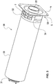
- the figure 3 illustrates a cartridge 30 according to a preferred embodiment of the invention, according to which the body of the filter element 3 is cylindrical and the latter is connected to an exhaust cover 4 of square shape and at the periphery of the corners of which four holes are provided for the insertion of fixing screws.
- the outlet orifice 22 is round in order to allow easy connection for example to an outlet pipe.
- the cartridge 30 remains symmetrical with respect to the axis of the filter element 3 constituted by the inlet nozzle 31, the closing nozzle 32 and the filtering intermediate part 33.
- the square shape as well as the dimensions of the cover d 'exhaust are preferably chosen to correspond to the usual shape of existing flanges and thus facilitate the plating against a bearing surface of the pump 1 during assembly, as well as to facilitate the arrangement of the polarizing devices at its periphery. It will however be understood that it is also possible to envisage fixing ears in the form of tongues projecting radially outwards, and which would be regularly spaced around arcs of circle of the same length, or even other geometric shapes. adequate, preferably symmetrical.
- the exhaust cover 4 is arranged in a single piece with the closure end piece 32, so that the connector 5 here constitutes only a fictitious intrinsic part, since it is impossible to determine where this intermediate junction piece begins behind the closing end piece 32 and where it stops at the level of the cover. However, we can distinguish, in this intermediate space, the guide surfaces 50 in the extension of the cylinder.
- the material used to make the end of this cartridge 30 by molding can consist, for example, of polyamide or polypropylene, or any suitable material capable of supporting a flow of air circulating around 80 ° C.
- a conductive material will preferably be chosen, such as for example polypropylene with the insertion of stainless steel fibers, in order to be able to reduce the level of static electricity as much as possible.
- This grid constitutes an advantageous variant for producing the noise attenuator 7, previously illustrated on the figure 2 : indeed, this allows on the one hand to guide the exhaust flow, and on the other hand, thanks to the successive passage of the air flow in small sections then larger, to reduce the noise level . Furthermore, instead of letting the air relax through a large hole, the fact that it is divided into a number of small holes or slits, increases the frequency of the generated sound, which has a more limited range, and thus helping to achieve the same desired goal of reducing noise pollution. Finally, this grid makes it possible to create a laminar flow eliminating the turbulence normally generated during blowing, consequently reducing the noise level all the more.
- This preferred embodiment illustrated by the figure 3 for the noise attenuator 7 also has two technical advantages: the first consists in performing the anti-noise attenuation function at the output without any part requiring a dedicated additional volume having to be provided specifically for this purpose, thus reducing the bulk, and the second being, in the case where the grid is designed in a modular manner relative to the connector 5 and to the baffle 6, to simplify its manufacturing process as well as to make its replacement independent of that of the parts in which it is intended to be inserted.
- Such a keying system makes it possible to correctly orient the baffle 6 to the inside the housing 2 so that the roof - constituted here by the side spoilers 61 clearly visible on the figure 4D , and which form an integral part of it - making it possible to retain the drops of oil formed by gravity at the outlet of the exhaust filter is oriented correctly.
- Other keying systems would also be possible, for example using a bayonet attachment, or with another number of screws and other geometric shapes for the exhaust cover 4; however, this variant proposed using pairs of holes and separate screws has the advantage of a particularly simple implementation.
- the figure 4C in the sagittal section plane BB makes it possible to highlight an anti-noise valve 9 at the level of the inlet nozzle 31 of the filter element 3, which makes it possible, jointly with the noise attenuator at outlet 7 (not illustrated in this figure), to maximize the sound insulation performance of the pumping work vis-à-vis the outside.
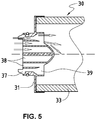
- Another possibility of noise reduction at the inlet end piece 31 of the filter element 3 is shown in figure 5 .
- the noise limiting valve 9 illustrated in the figure 4C can be replaced by a reduction in the cross-section of the air flow.
- the air (represented by the arrows) penetrates inside the filtering element 3 by a circular ring 37 and a series of holes 38 so that the air flow passing through the circular ring 37 is relaxed quickly thanks to the enlargement 39.
- This air flow then joins the air passing through the holes 38 tangentially by pressing it on the conical surface also shown in the figure 5 .
- This arrangement makes it possible to have the same noise damping as using the movable valve 9 while allowing the assembly to be produced in a single piece which is easy to machine. Reliability is also improved since there are only static parts left in the filter element 3.
- the integrated handle 8 has a particular shape, here in the shape of a "U” not interfering on the one hand with the extension of the orifice (that is to say, according to the embodiment, the second orifice of outlet 22 of said exhaust cover 4) so as not to disturb the flow of fluid during usual mode of operation of the vacuum pump 1.
- a "U” shape allows for a particularly easy and intuitive grip for the user, like a drawer: it suffices to introduce his fingers into the outlet 22 and then pull the exhaust cover 4 towards you.
- the integrated handle 8 is also arranged in a single piece, that is to say in one piece with the closure end piece 32 and the exhaust cover 4. It thus forms part integral with a fictitious junction piece between these two elements and as such, it can be considered that the integrated handle 8 is also preferably arranged in a single piece with the fitting 5, which makes it possible to simplify the machining process .
- the preferred embodiment illustrated refers to a one-piece type structure for the cartridge 30 proposed in the context of the present invention
- other variants are possible for assembling the different parts constitutive of this cartridge 30 having appeal to the various technical functions which they fulfill without departing from the scope of the invention.
- a cartridge 30 composed of such "spare parts” and these "spare parts” for the cartridge 30 are also part of the present invention at the same level as the cartridge 30 produced in a single piece.
- other geometric shapes, preferably symmetrical, are also possible for the exhaust cover and the filter element.
Landscapes
- Engineering & Computer Science (AREA)
- Mechanical Engineering (AREA)
- General Engineering & Computer Science (AREA)
- Chemical & Material Sciences (AREA)
- Chemical Kinetics & Catalysis (AREA)
- Physics & Mathematics (AREA)
- Geometry (AREA)
- Compressor (AREA)
- Applications Or Details Of Rotary Compressors (AREA)
- Jet Pumps And Other Pumps (AREA)
- Compressors, Vaccum Pumps And Other Relevant Systems (AREA)
- Filtering Of Dispersed Particles In Gases (AREA)
Applications Claiming Priority (3)
| Application Number | Priority Date | Filing Date | Title |
|---|---|---|---|
| PCT/EP2015/078226 WO2017092795A1 (fr) | 2015-12-01 | 2015-12-01 | Pompe a vide avec element filtrant |
| EP16812913.8A EP3384161B1 (de) | 2015-12-01 | 2016-12-01 | Vakuumpumpe mit filterelement |
| PCT/EP2016/079509 WO2017093441A1 (fr) | 2015-12-01 | 2016-12-01 | Pompe a vide avec element filtrant |
Related Parent Applications (1)
| Application Number | Title | Priority Date | Filing Date |
|---|---|---|---|
| EP16812913.8A Division EP3384161B1 (de) | 2015-12-01 | 2016-12-01 | Vakuumpumpe mit filterelement |
Publications (3)
| Publication Number | Publication Date |
|---|---|
| EP3663585A1 true EP3663585A1 (de) | 2020-06-10 |
| EP3663585B1 EP3663585B1 (de) | 2024-01-10 |
| EP3663585C0 EP3663585C0 (de) | 2024-01-10 |
Family
ID=54782696
Family Applications (2)
| Application Number | Title | Priority Date | Filing Date |
|---|---|---|---|
| EP16812913.8A Active EP3384161B1 (de) | 2015-12-01 | 2016-12-01 | Vakuumpumpe mit filterelement |
| EP20155484.7A Active EP3663585B1 (de) | 2015-12-01 | 2016-12-01 | Vakuumpumpe mit filterelement |
Family Applications Before (1)
| Application Number | Title | Priority Date | Filing Date |
|---|---|---|---|
| EP16812913.8A Active EP3384161B1 (de) | 2015-12-01 | 2016-12-01 | Vakuumpumpe mit filterelement |
Country Status (15)
| Country | Link |
|---|---|
| US (1) | US11319958B2 (de) |
| EP (2) | EP3384161B1 (de) |
| JP (1) | JP7097295B2 (de) |
| KR (2) | KR102894825B1 (de) |
| CN (2) | CN108291548B (de) |
| AU (2) | AU2016363589B2 (de) |
| BR (1) | BR112018010604B1 (de) |
| CA (1) | CA3006628C (de) |
| DK (1) | DK3384161T3 (de) |
| ES (2) | ES2775705T3 (de) |
| PL (2) | PL3384161T3 (de) |
| PT (1) | PT3384161T (de) |
| RU (1) | RU2730191C2 (de) |
| TW (2) | TWI708015B (de) |
| WO (2) | WO2017092795A1 (de) |
Families Citing this family (13)
| Publication number | Priority date | Publication date | Assignee | Title |
|---|---|---|---|---|
| EP3525908B1 (de) * | 2016-10-13 | 2022-09-07 | Cobham Mission Systems Davenport LSS Inc. | Verbesserte wassertrennung für ein system mit verwendung eines psa-verfahrens |
| DE102019105695A1 (de) * | 2019-03-06 | 2020-09-10 | Gebr. Becker Gmbh | Ölgeschmierte Drehschieber-Vakuumpumpe |
| WO2021111188A1 (en) * | 2019-12-02 | 2021-06-10 | Porvair Filtration Group Limited | Gas filtration apparatus |
| CN113929179A (zh) * | 2020-06-29 | 2022-01-14 | 浙江绍兴苏泊尔生活电器有限公司 | 用于净水机的泵组件、安装座组件、增压装置和净水机 |
| WO2022119251A1 (ko) | 2020-12-01 | 2022-06-09 | 주식회사 마이크로필터 | 정수필터 어셈블리 및 이를 포함하는 냉장고 |
| KR102493792B1 (ko) * | 2020-12-01 | 2023-01-31 | 주식회사 마이크로필터 | 정수필터 어셈블리 및 이를 포함하는 냉장고 |
| GB2603971A (en) * | 2021-02-19 | 2022-08-24 | Leybold Tianjin Int Trade Co Ltd | Filtering module for use with a vacuum pump |
| US12485459B2 (en) | 2021-07-08 | 2025-12-02 | Industrial Vacuum Transfer Services Usa, Llc | Systems, assemblies, and methods for pyrophoric material extraction |
| US12510077B2 (en) * | 2021-07-08 | 2025-12-30 | Industrial Vacuum Transfer Services Usa, Llc | Air compressor having vacuum and associated methods for loading and extracting materials |
| CN114504889A (zh) * | 2022-02-22 | 2022-05-17 | 阜宁裕隆环保材料有限公司 | 一种带有快捷安装结构的除尘器用除尘滤袋 |
| USD989226S1 (en) * | 2022-07-01 | 2023-06-13 | Brio Water Technology, Inc. | Filter |
| USD990620S1 (en) * | 2022-07-01 | 2023-06-27 | Brio Water Technology, Inc. | Filter |
| CN118273927B (zh) * | 2024-05-31 | 2024-09-24 | 山西辉能科技有限公司 | 一种真空泵前过滤器 |
Citations (9)
| Publication number | Priority date | Publication date | Assignee | Title |
|---|---|---|---|---|
| US1769153A (en) * | 1928-03-07 | 1930-07-01 | Meyer William Warren | Rotary blower or pump |
| FR2255933A1 (en) * | 1973-12-27 | 1975-07-25 | Sofep | Disposable monobloc air filter assembly for automobiles - in which the lid and filter element with baseplate are single rigid unit formed by fusion welding |
| US4350592A (en) * | 1979-04-19 | 1982-09-21 | Kronsbein Dirk G | Cartridge filter |
| EP0063656A1 (de) * | 1979-05-17 | 1982-11-03 | Ingersoll-Rand Company | Luft/Öl-Abscheidungsanlage und Ölspeicher |
| EP0538973A1 (de) * | 1991-10-23 | 1993-04-28 | MANNESMANN Aktiengesellschaft | Luftgekühlte Verdichteranlage |
| JPH10159781A (ja) * | 1996-12-03 | 1998-06-16 | Tokico Ltd | 圧縮機 |
| EP1034830A2 (de) | 1999-03-11 | 2000-09-13 | KRANTZ - TKT GmbH | Vorrichtung zur Filtration eines mit Aerosolen beladenen Gasstromes |
| US6152713A (en) * | 1997-08-29 | 2000-11-28 | Denso Corporation | Scroll type compressor |
| WO2008146045A1 (en) * | 2007-05-29 | 2008-12-04 | Psi Global Ltd | Improvements in coalescing filters |
Family Cites Families (44)
| Publication number | Priority date | Publication date | Assignee | Title |
|---|---|---|---|---|
| JPS5029162B1 (de) * | 1970-03-30 | 1975-09-20 | ||
| SU1687883A1 (ru) * | 1988-11-29 | 1991-10-30 | Научно-Исследовательский Институт Прикладной Физики Ташкентского Государственного Университета Им.В.И.Ленина | Способ получени вакуума |
| DE59802216D1 (de) * | 1997-08-26 | 2002-01-10 | Crt Common Rail Tech Ag | Spiralverdrängermaschine für kompressible Medien |
| JP2000153119A (ja) * | 1998-11-17 | 2000-06-06 | Babcock Hitachi Kk | フィルタ装置 |
| JP2003034732A (ja) * | 2001-07-24 | 2003-02-07 | Toray Ind Inc | ポリブチレンテレフタレート樹脂発泡成形品 |
| GB2414424B (en) * | 2002-06-07 | 2006-06-14 | Baldwin Filters Inc | Housing for environmentally friendly filter cartridge |
| US7168573B2 (en) * | 2002-06-07 | 2007-01-30 | Baldwin Filters, Inc. | Environmentally friendly filter cartridge |
| US7014761B2 (en) * | 2002-06-07 | 2006-03-21 | Baldwin Filters, Inc. | Environmentally friendly dual lube venturi filter cartridge |
| US6833023B1 (en) * | 2003-02-14 | 2004-12-21 | International Liner Co., Inc. | Air filter assembly |
| KR101188573B1 (ko) * | 2003-11-07 | 2012-10-05 | 감브로 룬디아 아베 | 필터용 펌프 호스를 지닌 단부 캡 조립체 및 이 단부 캡조립체를 포함하는 필터 |
| GB0417462D0 (en) * | 2004-08-05 | 2004-09-08 | Domnick Hunter Ltd | Filter element |
| GB0417464D0 (en) * | 2004-08-05 | 2004-09-08 | Domnick Hunter Ltd | Filter assembly |
| GB0417458D0 (en) * | 2004-08-05 | 2004-09-08 | Domnick Hunter Ltd | Filter assembly |
| US7291195B2 (en) * | 2005-11-23 | 2007-11-06 | Emerson Electric Co. | Durable filter cage for air-moving system |
| PL1870152T3 (pl) * | 2006-06-21 | 2018-10-31 | Donaldson Filtration Deutschland Gmbh | Filtr z wymiennym wkładem |
| EP2117671B1 (de) * | 2006-11-27 | 2013-03-27 | Ateliers Busch S.A. | Filterinstallationsvorrichtung |
| USD583389S1 (en) * | 2007-04-26 | 2008-12-23 | Ateliers Busch Sa | Exhaust filter for a vacuum pump |
| US8404029B2 (en) * | 2007-06-14 | 2013-03-26 | Donaldson Company, Inc. | Crankcase ventilation filter arrangments; components; and, methods |
| DE202008004288U1 (de) * | 2008-03-27 | 2009-08-06 | Mann+Hummel Gmbh | Filter |
| US8167966B2 (en) * | 2008-04-07 | 2012-05-01 | Cummins Filtration Ip, Inc. | Replaceable filter cartridge with removal feature |
| CN201218210Y (zh) * | 2008-05-28 | 2009-04-08 | 佛山市广顺电器有限公司 | 压缩机的进气装置 |
| CN201218200Y (zh) * | 2008-05-30 | 2009-04-08 | 上海通用汽车有限公司 | 一种可变排量的内啮合转子泵 |
| US8361181B2 (en) * | 2008-06-06 | 2013-01-29 | Donaldson Company, Inc. | Air cleaner assemblies; filter cartridges therefor; features; and, methods |
| JP5222054B2 (ja) * | 2008-07-23 | 2013-06-26 | Ckd株式会社 | 真空ユニット |
| US8268031B2 (en) * | 2008-09-11 | 2012-09-18 | Alstom Technology Ltd | Fabric filter system |
| ITRE20110078A1 (it) * | 2011-10-05 | 2013-04-06 | Ufi Filters Spa | Elemento collettore per una cartuccia filtrante |
| JP5804897B2 (ja) * | 2011-10-28 | 2015-11-04 | ホーコス株式会社 | 集塵機用フィルタ装置、集塵機、フィルタ交換方法 |
| CN102889212B (zh) * | 2012-10-30 | 2015-08-12 | 南通金坤机械设备有限公司 | 旋片高效节能环保真空泵 |
| EP3763432B1 (de) * | 2013-05-22 | 2022-03-30 | Donaldson Company, Inc. | Filterelement und luftreiniger |
| GB2520770A (en) * | 2013-12-02 | 2015-06-03 | Nano Porous Solutions Ltd | An end cap for a filter assembly |
| WO2015153363A1 (en) * | 2014-04-04 | 2015-10-08 | Cummins Filtration Ip, Inc. | Snap in place natural gas filter |
| CN204193737U (zh) * | 2014-10-20 | 2015-03-11 | 云南钛业股份有限公司 | 一种真空系统酸性气体除尘器 |
| CN107208580B (zh) * | 2014-12-10 | 2019-05-10 | Ufi过滤股份公司 | 导入内燃发动机的吸气进气口的空气的过滤器组 |
| CN104481878B (zh) * | 2014-12-12 | 2016-07-06 | 南通诺博特机器人制造有限公司 | 适用于砖瓦真空挤出的滑阀式真空泵 |
| DE102015014113A1 (de) * | 2015-11-04 | 2017-05-04 | Mann+Hummel Gmbh | Filterelement und Filteranordnung |
| ITUB20156823A1 (it) * | 2015-12-11 | 2017-06-11 | Ufi Filters Spa | Cartuccia filtrante aria con struttura interna |
| US11085444B2 (en) * | 2016-07-07 | 2021-08-10 | Hitachi Industrial Equipment Systems Co., Ltd. | Scroll-type fluid machine |
| WO2018050231A1 (en) * | 2016-09-15 | 2018-03-22 | Mahle International Gmbh | Air filter |
| DE102016012325A1 (de) * | 2016-10-17 | 2018-04-19 | Mann + Hummel Gmbh | Rundfilterelement, insbesondere zur Gasfiltration |
| DE102016012327A1 (de) * | 2016-10-17 | 2018-04-19 | Mann + Hummel Gmbh | Rundfilterelement, insbesondere zur Gasfiltration |
| DE112018000382T5 (de) * | 2017-02-21 | 2019-09-26 | Cummins Filtration Ip, Inc. | Gewellte ineinandergreifende Gehäuse-Endplatten-Schnittstellengeometrie |
| DE102018000538A1 (de) * | 2018-01-24 | 2019-07-25 | Mann+Hummel Gmbh | Filtergehäuse für eine Filtereinrichtung |
| US11331610B2 (en) * | 2018-12-21 | 2022-05-17 | Ingersoll-Rand Industrial U.S., Inc. | Filter system and replaceable filter cartridge |
| US11136948B2 (en) * | 2019-03-13 | 2021-10-05 | Mann+Hummel Gmbh | Multi-modal multi-media air filtration system |
-
2015
- 2015-12-01 WO PCT/EP2015/078226 patent/WO2017092795A1/fr not_active Ceased
-
2016
- 2016-12-01 JP JP2018527929A patent/JP7097295B2/ja active Active
- 2016-12-01 KR KR1020247012814A patent/KR102894825B1/ko active Active
- 2016-12-01 CN CN201680070635.6A patent/CN108291548B/zh active Active
- 2016-12-01 TW TW105139707A patent/TWI708015B/zh active
- 2016-12-01 WO PCT/EP2016/079509 patent/WO2017093441A1/fr not_active Ceased
- 2016-12-01 CN CN202010668849.1A patent/CN111894853B/zh active Active
- 2016-12-01 KR KR1020187018871A patent/KR102659707B1/ko active Active
- 2016-12-01 EP EP16812913.8A patent/EP3384161B1/de active Active
- 2016-12-01 ES ES16812913T patent/ES2775705T3/es active Active
- 2016-12-01 PL PL16812913T patent/PL3384161T3/pl unknown
- 2016-12-01 TW TW109130977A patent/TWI764271B/zh active
- 2016-12-01 PT PT168129138T patent/PT3384161T/pt unknown
- 2016-12-01 AU AU2016363589A patent/AU2016363589B2/en active Active
- 2016-12-01 BR BR112018010604-6A patent/BR112018010604B1/pt active IP Right Grant
- 2016-12-01 CA CA3006628A patent/CA3006628C/fr active Active
- 2016-12-01 DK DK16812913.8T patent/DK3384161T3/da active
- 2016-12-01 US US15/777,717 patent/US11319958B2/en active Active
- 2016-12-01 RU RU2018123175A patent/RU2730191C2/ru active
- 2016-12-01 PL PL20155484.7T patent/PL3663585T3/pl unknown
- 2016-12-01 ES ES20155484T patent/ES2971224T3/es active Active
- 2016-12-01 EP EP20155484.7A patent/EP3663585B1/de active Active
-
2020
- 2020-12-04 AU AU2020281134A patent/AU2020281134B2/en active Active
Patent Citations (9)
| Publication number | Priority date | Publication date | Assignee | Title |
|---|---|---|---|---|
| US1769153A (en) * | 1928-03-07 | 1930-07-01 | Meyer William Warren | Rotary blower or pump |
| FR2255933A1 (en) * | 1973-12-27 | 1975-07-25 | Sofep | Disposable monobloc air filter assembly for automobiles - in which the lid and filter element with baseplate are single rigid unit formed by fusion welding |
| US4350592A (en) * | 1979-04-19 | 1982-09-21 | Kronsbein Dirk G | Cartridge filter |
| EP0063656A1 (de) * | 1979-05-17 | 1982-11-03 | Ingersoll-Rand Company | Luft/Öl-Abscheidungsanlage und Ölspeicher |
| EP0538973A1 (de) * | 1991-10-23 | 1993-04-28 | MANNESMANN Aktiengesellschaft | Luftgekühlte Verdichteranlage |
| JPH10159781A (ja) * | 1996-12-03 | 1998-06-16 | Tokico Ltd | 圧縮機 |
| US6152713A (en) * | 1997-08-29 | 2000-11-28 | Denso Corporation | Scroll type compressor |
| EP1034830A2 (de) | 1999-03-11 | 2000-09-13 | KRANTZ - TKT GmbH | Vorrichtung zur Filtration eines mit Aerosolen beladenen Gasstromes |
| WO2008146045A1 (en) * | 2007-05-29 | 2008-12-04 | Psi Global Ltd | Improvements in coalescing filters |
Also Published As
Similar Documents
| Publication | Publication Date | Title |
|---|---|---|
| EP3384161B1 (de) | Vakuumpumpe mit filterelement | |
| CA2946958C (fr) | Module de turbomachine comportant un carter autour d'un equipement avec un capot de recuperation d'huile de lubrification | |
| CA2774440C (fr) | Chambre de combustion de turbomachine aeronautique avec trous de combustion de configurations differentes | |
| FR3020472A1 (fr) | Dispositif de connexion de branches de lunettes sur la face frontale | |
| CA2754419A1 (fr) | Chambre de combustion de turbomachine comprenant des moyens ameliores d'alimentation en air | |
| EP2479415B1 (de) | Triebwerk mit einem Lärmreduzierungssystem | |
| EP2497385A1 (de) | Abnehmbarer Schalldämpfer für Haartrockner, und mit einem solchen Schalldämpfer ausgestatteter Haartrockner | |
| EP3489499A1 (de) | Innenstruktur eines primären ausstossrohrs | |
| FR3103527A1 (fr) | Elément de séparation de module hydraulique antivibratoire et module hydraulique antivibratoire équipé d’un tel élément de séparation | |
| WO2016193584A1 (fr) | Dispositif d'atténuation des bruits de bouche et des bruits rayonnés | |
| EP1255071A1 (de) | Schalldämmungsanordnung in einem Kreislauf eines Gasfluidums | |
| EP1433948B1 (de) | Luftansaugdämpfungsanlage | |
| CA2761601C (fr) | Turbomoteur comportant un cone de guidage des gaz d'echappement avec un attenuateur sonore | |
| FR2910529A3 (fr) | Systeme hydraulique pour le rattrapage de jeu des soupapes des moteurs a combustion interne | |
| FR3027973A1 (fr) | Carter de turbomachine, comprenant un dispositif de guidage de l'air en rotation dans le carter | |
| FR3061933B1 (fr) | Structure interne d'un conduit d'ejection primaire | |
| FR3092913A1 (fr) | Sonde de reniflage et détecteur de fuites | |
| CA2647401C (fr) | Ensemble de distribution de fluide et utilisation correspondante | |
| FR2903459A1 (fr) | Pompe a engrenages comportant un dispositif d'amortissement de pulsations d'aspiration de fluide hydraulique | |
| CA2636628A1 (fr) | Dispositif de pompage | |
| FR3048462A1 (fr) | Pompe, notamment a palettes lubrifiees | |
| FR3067792A1 (fr) | Injecteur de carburant a jet plat pour une turbomachine d'aeronef et son procede de fabrication | |
| FR2897399A1 (fr) | Pompe hydraulique, notamment de groupe electro-pompe en particulier pour la direction assistee de vehicule automobile | |
| EP3029954B1 (de) | Subwoofer mit aufbewahrungsfach | |
| FR2632020A1 (fr) | Dispositif tournant a engrenages pour la circulation d'un liquide |
Legal Events
| Date | Code | Title | Description |
|---|---|---|---|
| PUAI | Public reference made under article 153(3) epc to a published international application that has entered the european phase |
Free format text: ORIGINAL CODE: 0009012 |
|
| STAA | Information on the status of an ep patent application or granted ep patent |
Free format text: STATUS: THE APPLICATION HAS BEEN PUBLISHED |
|
| AC | Divisional application: reference to earlier application |
Ref document number: 3384161 Country of ref document: EP Kind code of ref document: P |
|
| AK | Designated contracting states |
Kind code of ref document: A1 Designated state(s): AL AT BE BG CH CY CZ DE DK EE ES FI FR GB GR HR HU IE IS IT LI LT LU LV MC MK MT NL NO PL PT RO RS SE SI SK SM TR |
|
| STAA | Information on the status of an ep patent application or granted ep patent |
Free format text: STATUS: REQUEST FOR EXAMINATION WAS MADE |
|
| 17P | Request for examination filed |
Effective date: 20201116 |
|
| RBV | Designated contracting states (corrected) |
Designated state(s): AL AT BE BG CH CY CZ DE DK EE ES FI FR GB GR HR HU IE IS IT LI LT LU LV MC MK MT NL NO PL PT RO RS SE SI SK SM TR |
|
| STAA | Information on the status of an ep patent application or granted ep patent |
Free format text: STATUS: EXAMINATION IS IN PROGRESS |
|
| 17Q | First examination report despatched |
Effective date: 20210802 |
|
| GRAP | Despatch of communication of intention to grant a patent |
Free format text: ORIGINAL CODE: EPIDOSNIGR1 |
|
| STAA | Information on the status of an ep patent application or granted ep patent |
Free format text: STATUS: GRANT OF PATENT IS INTENDED |
|
| INTG | Intention to grant announced |
Effective date: 20230724 |
|
| GRAS | Grant fee paid |
Free format text: ORIGINAL CODE: EPIDOSNIGR3 |
|
| GRAA | (expected) grant |
Free format text: ORIGINAL CODE: 0009210 |
|
| STAA | Information on the status of an ep patent application or granted ep patent |
Free format text: STATUS: THE PATENT HAS BEEN GRANTED |
|
| AC | Divisional application: reference to earlier application |
Ref document number: 3384161 Country of ref document: EP Kind code of ref document: P |
|
| AK | Designated contracting states |
Kind code of ref document: B1 Designated state(s): AL AT BE BG CH CY CZ DE DK EE ES FI FR GB GR HR HU IE IS IT LI LT LU LV MC MK MT NL NO PL PT RO RS SE SI SK SM TR |
|
| REG | Reference to a national code |
Ref country code: GB Ref legal event code: FG4D Free format text: NOT ENGLISH |
|
| REG | Reference to a national code |
Ref country code: CH Ref legal event code: EP |
|
| REG | Reference to a national code |
Ref country code: DE Ref legal event code: R096 Ref document number: 602016085325 Country of ref document: DE |
|
| REG | Reference to a national code |
Ref country code: IE Ref legal event code: FG4D Free format text: LANGUAGE OF EP DOCUMENT: FRENCH |
|
| U01 | Request for unitary effect filed |
Effective date: 20240131 |
|
| U07 | Unitary effect registered |
Designated state(s): AT BE BG DE DK EE FI FR IT LT LU LV MT NL PT SE SI Effective date: 20240205 |
|
| REG | Reference to a national code |
Ref country code: ES Ref legal event code: FG2A Ref document number: 2971224 Country of ref document: ES Kind code of ref document: T3 Effective date: 20240604 |
|
| PG25 | Lapsed in a contracting state [announced via postgrant information from national office to epo] |
Ref country code: IS Free format text: LAPSE BECAUSE OF FAILURE TO SUBMIT A TRANSLATION OF THE DESCRIPTION OR TO PAY THE FEE WITHIN THE PRESCRIBED TIME-LIMIT Effective date: 20240510 |
|
| PG25 | Lapsed in a contracting state [announced via postgrant information from national office to epo] |
Ref country code: GR Free format text: LAPSE BECAUSE OF FAILURE TO SUBMIT A TRANSLATION OF THE DESCRIPTION OR TO PAY THE FEE WITHIN THE PRESCRIBED TIME-LIMIT Effective date: 20240411 |
|
| PG25 | Lapsed in a contracting state [announced via postgrant information from national office to epo] |
Ref country code: HR Free format text: LAPSE BECAUSE OF FAILURE TO SUBMIT A TRANSLATION OF THE DESCRIPTION OR TO PAY THE FEE WITHIN THE PRESCRIBED TIME-LIMIT Effective date: 20240110 Ref country code: RS Free format text: LAPSE BECAUSE OF FAILURE TO SUBMIT A TRANSLATION OF THE DESCRIPTION OR TO PAY THE FEE WITHIN THE PRESCRIBED TIME-LIMIT Effective date: 20240410 |
|
| PG25 | Lapsed in a contracting state [announced via postgrant information from national office to epo] |
Ref country code: RS Free format text: LAPSE BECAUSE OF FAILURE TO SUBMIT A TRANSLATION OF THE DESCRIPTION OR TO PAY THE FEE WITHIN THE PRESCRIBED TIME-LIMIT Effective date: 20240410 Ref country code: NO Free format text: LAPSE BECAUSE OF FAILURE TO SUBMIT A TRANSLATION OF THE DESCRIPTION OR TO PAY THE FEE WITHIN THE PRESCRIBED TIME-LIMIT Effective date: 20240410 Ref country code: IS Free format text: LAPSE BECAUSE OF FAILURE TO SUBMIT A TRANSLATION OF THE DESCRIPTION OR TO PAY THE FEE WITHIN THE PRESCRIBED TIME-LIMIT Effective date: 20240510 Ref country code: HR Free format text: LAPSE BECAUSE OF FAILURE TO SUBMIT A TRANSLATION OF THE DESCRIPTION OR TO PAY THE FEE WITHIN THE PRESCRIBED TIME-LIMIT Effective date: 20240110 Ref country code: GR Free format text: LAPSE BECAUSE OF FAILURE TO SUBMIT A TRANSLATION OF THE DESCRIPTION OR TO PAY THE FEE WITHIN THE PRESCRIBED TIME-LIMIT Effective date: 20240411 |
|
| REG | Reference to a national code |
Ref country code: DE Ref legal event code: R097 Ref document number: 602016085325 Country of ref document: DE |
|
| PG25 | Lapsed in a contracting state [announced via postgrant information from national office to epo] |
Ref country code: SM Free format text: LAPSE BECAUSE OF FAILURE TO SUBMIT A TRANSLATION OF THE DESCRIPTION OR TO PAY THE FEE WITHIN THE PRESCRIBED TIME-LIMIT Effective date: 20240110 |
|
| PG25 | Lapsed in a contracting state [announced via postgrant information from national office to epo] |
Ref country code: CZ Free format text: LAPSE BECAUSE OF FAILURE TO SUBMIT A TRANSLATION OF THE DESCRIPTION OR TO PAY THE FEE WITHIN THE PRESCRIBED TIME-LIMIT Effective date: 20240110 |
|
| PG25 | Lapsed in a contracting state [announced via postgrant information from national office to epo] |
Ref country code: SK Free format text: LAPSE BECAUSE OF FAILURE TO SUBMIT A TRANSLATION OF THE DESCRIPTION OR TO PAY THE FEE WITHIN THE PRESCRIBED TIME-LIMIT Effective date: 20240110 |
|
| PG25 | Lapsed in a contracting state [announced via postgrant information from national office to epo] |
Ref country code: SM Free format text: LAPSE BECAUSE OF FAILURE TO SUBMIT A TRANSLATION OF THE DESCRIPTION OR TO PAY THE FEE WITHIN THE PRESCRIBED TIME-LIMIT Effective date: 20240110 Ref country code: SK Free format text: LAPSE BECAUSE OF FAILURE TO SUBMIT A TRANSLATION OF THE DESCRIPTION OR TO PAY THE FEE WITHIN THE PRESCRIBED TIME-LIMIT Effective date: 20240110 Ref country code: RO Free format text: LAPSE BECAUSE OF FAILURE TO SUBMIT A TRANSLATION OF THE DESCRIPTION OR TO PAY THE FEE WITHIN THE PRESCRIBED TIME-LIMIT Effective date: 20240110 Ref country code: CZ Free format text: LAPSE BECAUSE OF FAILURE TO SUBMIT A TRANSLATION OF THE DESCRIPTION OR TO PAY THE FEE WITHIN THE PRESCRIBED TIME-LIMIT Effective date: 20240110 |
|
| PLBE | No opposition filed within time limit |
Free format text: ORIGINAL CODE: 0009261 |
|
| STAA | Information on the status of an ep patent application or granted ep patent |
Free format text: STATUS: NO OPPOSITION FILED WITHIN TIME LIMIT |
|
| 26N | No opposition filed |
Effective date: 20241011 |
|
| U20 | Renewal fee for the european patent with unitary effect paid |
Year of fee payment: 9 Effective date: 20241205 |
|
| REG | Reference to a national code |
Ref country code: CH Ref legal event code: U11 Free format text: ST27 STATUS EVENT CODE: U-0-0-U10-U11 (AS PROVIDED BY THE NATIONAL OFFICE) Effective date: 20260101 |
|
| PGFP | Annual fee paid to national office [announced via postgrant information from national office to epo] |
Ref country code: GB Payment date: 20251219 Year of fee payment: 10 |
|
| PGFP | Annual fee paid to national office [announced via postgrant information from national office to epo] |
Ref country code: MC Payment date: 20251223 Year of fee payment: 10 |
|
| U20 | Renewal fee for the european patent with unitary effect paid |
Year of fee payment: 10 Effective date: 20251205 |
|
| PGFP | Annual fee paid to national office [announced via postgrant information from national office to epo] |
Ref country code: TR Payment date: 20251125 Year of fee payment: 10 |
|
| PGFP | Annual fee paid to national office [announced via postgrant information from national office to epo] |
Ref country code: IE Payment date: 20251219 Year of fee payment: 10 |
|
| PGFP | Annual fee paid to national office [announced via postgrant information from national office to epo] |
Ref country code: PL Payment date: 20251125 Year of fee payment: 10 |
|
| PG25 | Lapsed in a contracting state [announced via postgrant information from national office to epo] |
Ref country code: CY Free format text: LAPSE BECAUSE OF FAILURE TO SUBMIT A TRANSLATION OF THE DESCRIPTION OR TO PAY THE FEE WITHIN THE PRESCRIBED TIME-LIMIT; INVALID AB INITIO Effective date: 20161201 |
|
| PGFP | Annual fee paid to national office [announced via postgrant information from national office to epo] |
Ref country code: ES Payment date: 20260130 Year of fee payment: 10 |
|
| PGFP | Annual fee paid to national office [announced via postgrant information from national office to epo] |
Ref country code: CH Payment date: 20260101 Year of fee payment: 10 |