EP3663596A1 - Boulon avec une hélice pour taraudage d'un filet - Google Patents
Boulon avec une hélice pour taraudage d'un filet Download PDFInfo
- Publication number
- EP3663596A1 EP3663596A1 EP19218992.6A EP19218992A EP3663596A1 EP 3663596 A1 EP3663596 A1 EP 3663596A1 EP 19218992 A EP19218992 A EP 19218992A EP 3663596 A1 EP3663596 A1 EP 3663596A1
- Authority
- EP
- European Patent Office
- Prior art keywords
- helix
- thread
- bolt
- profile
- threaded insert
- Prior art date
- Legal status (The legal status is an assumption and is not a legal conclusion. Google has not performed a legal analysis and makes no representation as to the accuracy of the status listed.)
- Granted
Links
Images


Classifications
-
- F—MECHANICAL ENGINEERING; LIGHTING; HEATING; WEAPONS; BLASTING
- F16—ENGINEERING ELEMENTS AND UNITS; GENERAL MEASURES FOR PRODUCING AND MAINTAINING EFFECTIVE FUNCTIONING OF MACHINES OR INSTALLATIONS; THERMAL INSULATION IN GENERAL
- F16B—DEVICES FOR FASTENING OR SECURING CONSTRUCTIONAL ELEMENTS OR MACHINE PARTS TOGETHER, e.g. NAILS, BOLTS, CIRCLIPS, CLAMPS, CLIPS OR WEDGES; JOINTS OR JOINTING
- F16B25/00—Screws that cut thread in the body into which they are screwed, e.g. wood screws
- F16B25/0005—Screws that cut thread in the body into which they are screwed, e.g. wood screws of the helical wire type
-
- F—MECHANICAL ENGINEERING; LIGHTING; HEATING; WEAPONS; BLASTING
- F16—ENGINEERING ELEMENTS AND UNITS; GENERAL MEASURES FOR PRODUCING AND MAINTAINING EFFECTIVE FUNCTIONING OF MACHINES OR INSTALLATIONS; THERMAL INSULATION IN GENERAL
- F16B—DEVICES FOR FASTENING OR SECURING CONSTRUCTIONAL ELEMENTS OR MACHINE PARTS TOGETHER, e.g. NAILS, BOLTS, CIRCLIPS, CLAMPS, CLIPS OR WEDGES; JOINTS OR JOINTING
- F16B37/00—Nuts or like thread-engaging members
- F16B37/12—Nuts or like thread-engaging members with thread-engaging surfaces formed by inserted coil-springs, discs, or the like; Independent pieces of wound wire used as nuts; Threaded inserts for holes
- F16B37/122—Threaded inserts, e.g. "rampa bolts"
- F16B37/125—Threaded inserts, e.g. "rampa bolts" the external surface of the insert being threaded
- F16B37/127—Threaded inserts, e.g. "rampa bolts" the external surface of the insert being threaded and self-tapping
-
- F—MECHANICAL ENGINEERING; LIGHTING; HEATING; WEAPONS; BLASTING
- F16—ENGINEERING ELEMENTS AND UNITS; GENERAL MEASURES FOR PRODUCING AND MAINTAINING EFFECTIVE FUNCTIONING OF MACHINES OR INSTALLATIONS; THERMAL INSULATION IN GENERAL
- F16B—DEVICES FOR FASTENING OR SECURING CONSTRUCTIONAL ELEMENTS OR MACHINE PARTS TOGETHER, e.g. NAILS, BOLTS, CIRCLIPS, CLAMPS, CLIPS OR WEDGES; JOINTS OR JOINTING
- F16B25/00—Screws that cut thread in the body into which they are screwed, e.g. wood screws
- F16B25/0036—Screws that cut thread in the body into which they are screwed, e.g. wood screws characterised by geometric details of the screw
- F16B25/0042—Screws that cut thread in the body into which they are screwed, e.g. wood screws characterised by geometric details of the screw characterised by the geometry of the thread, the thread being a ridge wrapped around the shaft of the screw
- F16B25/0052—Screws that cut thread in the body into which they are screwed, e.g. wood screws characterised by geometric details of the screw characterised by the geometry of the thread, the thread being a ridge wrapped around the shaft of the screw the ridge having indentations, notches or the like in order to improve the cutting behaviour
-
- F—MECHANICAL ENGINEERING; LIGHTING; HEATING; WEAPONS; BLASTING
- F16—ENGINEERING ELEMENTS AND UNITS; GENERAL MEASURES FOR PRODUCING AND MAINTAINING EFFECTIVE FUNCTIONING OF MACHINES OR INSTALLATIONS; THERMAL INSULATION IN GENERAL
- F16B—DEVICES FOR FASTENING OR SECURING CONSTRUCTIONAL ELEMENTS OR MACHINE PARTS TOGETHER, e.g. NAILS, BOLTS, CIRCLIPS, CLAMPS, CLIPS OR WEDGES; JOINTS OR JOINTING
- F16B33/00—Features common to bolt and nut
- F16B33/006—Non-metallic fasteners using screw-thread
Definitions
- the present invention is in the field of anchoring technology and comprises a helix for transmitting torque to a threaded insert sleeve and / or for tapping a thread, a bolt which is suitable for use with this helix, a threaded insert with this helix and a method for Making this helix.
- Threaded inserts are used to connect different components, whereby the components can consist of the same or different materials. Examples are steel-plastic, plastic-plastic, steel-steel, steel-aluminum, aluminum-aluminum, steel-wood, wood-wood and wood-concrete connections. Threaded inserts with self-tapping external threads for screwing into masonry or concrete are of particular practical importance.
- Threaded inserts usually have an internal thread and an external thread.
- the threaded insert is screwed via its external thread into a borehole in the component to be connected or in the material.
- the connection to another component can then be established via a connecting bolt by screwing the connecting bolt into the threaded insert.
- Threaded inserts can already be inserted into the component to be connected during component production or subsequently, e.g. be inserted into the component for repair purposes.
- a threaded insert which comprises an internal thread and an external thread and which is made from a solid workpiece, is used in the EP 1 085 220 B1 described.
- Another thread insert which also has an internal and an external thread, but is wound from a profile strip, is from the DE 10 2007 054 798 B3 known. Compared to other thread inserts, this wound thread insert has the advantage that it can be manufactured more cost-effectively due to the low material and manufacturing costs.
- a disadvantage of the wound thread insert mentioned is that it is not optimally suitable for tapping a thread. On the one hand, this is due to the fact that the required drive torque cannot easily be transferred via the wound profile strip to a leading part of the thread insert, on which the thread is to be tapped, without the profile strip helix twisting.
- the thread material must have a certain hardness for the purpose of furrowing. However, hardening usually also increases the brittleness of the material.
- the profile strip must not be too brittle, on the one hand because the material's formability is limited, on the other hand because the product properties require the material to be ductile.
- the torque transmission via an excessively brittle profile strip, which was only hardened after winding is critical because the profile strip may also break.
- Another disadvantage of using a hardenable material for a profile strip of a wound thread insert is that such materials are not very corrosion-resistant.
- the present invention has for its object to solve the problems described above.
- the present invention comprises a helix for transmitting a torque to a threaded insert sleeve with an external thread and / or for tapping a thread.
- the helix comprises a radially outer profile, which is used to anchor the helix in a threaded insert sleeve and to transmit a torque to the Threaded insert sleeve is determined.
- the outer profile can also be designed to form a thread.
- the helix comprises a drive profile which is suitable for receiving a drive which can engage in the drive profile in such a way that a torque can be transmitted from the drive to the helix and, at the same time, torsion of the helix is restricted or avoided.
- the torque can be transmitted to the threaded insert sleeve directly in the area of the leading end using the helix according to the invention, which can be anchored in the area of the leading end of the threaded insert sleeve.
- the torque transmission can be carried out using a drive tool that - through the threaded insert sleeve - can engage the drive profile with a suitable drive and can transmit the torque, for example when rotating about a longitudinal axis, via the helix to the threaded insert sleeve.
- the shape of the helix can be stabilized so that the helix is not subjected to any torsion when the torque is transmitted. For this reason, that portion of the threaded insert sleeve in which the helix is anchored also remains dimensionally stable during torque transmission, so that this portion of the threaded insert sleeve likewise does not experience any torsion.
- the helix With its radially outer profile, the helix can not only be anchored in the threaded insert sleeve and transmit the torque to it, but also optionally also thread a thread for the subsequent external thread of the threaded insert sleeve into the borehole, into which the threaded insert sleeve simultaneously is screwed in or "drawn in” via the helix.
- threaded insert sleeves can also be used for anchoring using the helix, the use of which would not be possible without the helix because they cannot be introduced into a borehole by torque transmission in the region of their rear end.
- inexpensive wound threaded insert sleeves can be used, which are only torsionally stable to a limited extent, and which can also be uncured and corrosion-resistant because the thread can be grooved through the outer profile of the helix.
- the helix can also be used exclusively for thread grooving - that is, not in addition to introducing a torque into the leading end of a sleeve.
- the helix is formed from a strip of material that extends helically around a longitudinal axis. This means that relatively little material is required to manufacture the helix and that it can be manufactured inexpensively.
- the length of the material strip preferably corresponds to at least the length of a helical gear and is particularly preferably longer than the length of a helical gear.
- the drive profile can comprise a plurality of cutouts, at least two cutouts being spaced apart from one another along the strip of material with the length of a spiral passage, so that these cutouts are aligned along the longitudinal axis.
- a suitable drive can be received along the longitudinal axis and engage in the aligned recesses, as a result of which a torque can be transmitted to the helix and the helix is simultaneously stabilized or "locked" against twisting.
- the helix can also have at least two helix gears.
- the drive profile preferably comprises a plurality of pairs of cutouts, each pair of cutouts being spaced apart from one another by the length of a spiral passage and being aligned along the longitudinal axis.
- the radially outer profile of the helix can comprise a plurality of outer projections, for example cutting teeth or furrowing teeth that are well suited for furrowing.
- the radially outer projections are spaced apart from one another along the strip of material and are arranged on the outside of the helix, from which they extend radially outwards. Because such projections extend radially outward, they can transmit a torque to the threaded insert sleeve perpendicular to this direction - that is to say in the circumferential direction.
- the helix is at least partially formed from a hardenable metal. Because a hardened metal is less easy to deform or process, the helix can first be brought into the intended shape during manufacture and then hardened. A high hardness is advantageous for the formation of a thread. Because the helix is stabilized by a drive during furrow and because torsion of the helix is avoided, the risk of the helix breaking even when the helix is very brittle does not exist or is at least slight.
- the helix is formed from a hardened metal which has a hardness of 58 58 HRC, preferably ⁇ 63 HRC and particularly preferably von 67 HRC.
- the HRC unit denotes the Rockwell hardness according to ISO 6508-1 (1997).
- a steel helix can be hardened, for example, by increasing the carbon content in the steel.
- the helix is formed from a bimetal which comprises a heat-treatable steel and a high-speed steel.
- the combination of the materials has the advantage that when the two materials are heat treated appropriately, the heat-treatable steel has a tough yet non-deformable heat-treatable structure, but the high-speed steel still has very high hardness and wear resistance.
- a tempered steel is therefore more malleable and bendable than high-speed steel, whereas the harder high-speed steel is more suitable for thread grooving is.
- the carbon content of a tempered steel can be, for example, between 0.2 and 0.7% and the carbon content of a high-speed steel can be up to over 2%.
- the bent helical region and the drive profile of the helix are preferably formed at least partially from tempered steel and the radially outer profile at least partially from high-speed steel.
- the bent helical region is to be understood as the region of the helix which lies between the radially outer profile and the drive profile. It should be noted that in the present description a "bimetal" not only denotes metals with only two components, but is also intended to denote metals which consist of more than two components.
- the diameter of the envelope of the radially outer profile can become smaller along a helix section which is adjacent to a leading end of the helix in the direction of the leading end of the helix. This simplifies the placement of the helix in a borehole and facilitates thread grooving.
- Said section preferably has at least the length of half, and particularly preferably at least the length of an entire spiral flight.
- the drive profile can have the shape of a hexagon socket, an inner polygon or an inner polygon, so that the helix can accommodate conventional drive geometries and can be driven by them.
- the present invention further comprises a threaded insert which comprises a coil according to the invention according to one of the aforementioned embodiments and a threaded insert sleeve.
- the threaded insert sleeve comprises an external thread with which the threaded insert can be screwed into a borehole.
- the helix is positively connected to the threaded insert sleeve via its radially outer profile, so that a torque transmitted to the helix via the drive profile is transmitted to the threaded insert sleeve.
- the helix is at least partially arranged in the leading half and preferably at the leading end of the threaded insert sleeve, so that the torque is transmitted to the threaded insert sleeve at least partially in the leading half and preferably at the leading end of the threaded insert sleeve.
- An anchoring bolt can preferably be anchored in the threaded insert sleeve, for example screwed into an internal thread provided in the threaded insert sleeve. Because the threaded insert according to the invention does not necessarily have to be driven via its rear end, but rather via its leading end can be driven, it is possible to "pull" the thread insert through its driven leading section to a certain extent into the borehole. In the driven leading section, a thread for the subsequent non-stabilized section of the threaded insert sleeve can be tapped into a borehole via the outer profile of the helix and / or via the driven section of the threaded insert sleeve stabilized and to a certain extent "splinted".
- the threaded insert according to the invention has the advantage that it can be used for it inexpensive and corrosion-resistant threaded insert sleeves which can be made from comparatively little material and for which screwing in is made considerably easier or even made possible due to the helix.
- the radially outer profile of the helix which transmits the torque to the threaded insert sleeve, can penetrate the threaded insert sleeve and form sections of the external thread. With these external thread sections formed by the helix, a thread can be grooved, into which the subsequent external thread of the threaded insert sleeve is drawn in and engages when the threaded insert is screwed in.
- the positive connection between the helix and the threaded insert sleeve can also be non-positive and / or integral.
- the threaded insert sleeve and the helix do not necessarily have to consist of the same material, but can at least partially also be formed from different materials.
- the threaded insert sleeve can be formed from a corrosion-resistant material, in particular from stainless steel. Corrosion-resistant materials are usually difficult to harden, so that such materials are not suitable for grooving a thread. Due to the combination with a hardened helix, the threaded insert can be self-tapping screwed into a borehole without the threaded insert sleeve itself having to be suitable for furrowing, the threaded insert sleeve in particular also being corrosion-resistant.
- the threaded insert can be used to provide a reliable and inexpensive long-term anchoring bolt without additional corrosion protection, for example by sealing the borehole or the like.
- the threaded insert sleeve can also consist at least partially, preferably predominantly of plastic.
- the threaded insert sleeve comprises a wound profile strip, which is preformed on one side with the profile of the external thread and on the other side with the profile of an internal thread.
- a threaded insert with a helix and a wound profile strip requires little material for production on the one hand and can be produced with comparatively little production effort.
- the helix can thread a thread for the wound profile strip into the borehole and pull the external thread of the wound profile strip into or into the grooved thread via the leading end of the thread insert. This significantly facilitates or enables the insertion of a threaded insert sleeve wound from a profiled strip into a non-threaded borehole.
- the helix pitch of the helix corresponds at least approximately to the winding pitch of the profile strip.
- the winding pitch of the profile strip preferably also corresponds at least approximately to the pitch of the external thread, so that the torque is additionally at least partially transmitted along the external thread profile, which further facilitates the pulling-in.
- the threaded insert sleeve has a head section which projects radially over the rest of the threaded insert sleeve.
- the thread insert can be used, for example, to fasten certain components to other components, for example insulation boards on a concrete wall or concrete ceiling.
- the term "thread insert” is not intended to suggest within the scope of the present disclosure that it should be introduced over its entire length into a substrate, for example concrete.
- the threaded insert sleeve comprises a plastic sleeve or is formed by a plastic sleeve, it being possible for the helix to be extrusion-coated with the plastic of the threaded insert sleeve.
- the threaded insert sleeve can comprise an internal thread into which the anchoring bolt is screwed.
- the threaded insert sleeve can also have an unthreaded inner wall, in particular a smooth inner wall, so that an anchoring bolt can thread a thread into the threaded insert sleeve for its anchoring in the threaded insert sleeve.
- Such a threaded insert sleeve made of plastic can then be screwed in with the aid of a tool which is inserted through a cavity in the sleeve and received by the drive profile of the helix.
- a drive element is permanently arranged in the threaded insert sleeve.
- the drive element has a first profile near a leading end, which engages with the drive profile of the helix, and a second profile near a rear end, which can be brought into engagement with a drive tool.
- the second profile can be surrounded by plastic, in particular by injection molding of plastic.
- An embodiment with a drive element permanently arranged in the threaded insert sleeve has the advantage, among other things, that assembly is facilitated and that the threaded insert then no longer has to be accessible from the outside for a tool.
- the drive element which is permanently arranged in the threaded insert sleeve, can mainly be made of a metallic material that allows torque transmission to the helix and also gives the plastic sleeve increased tensile strength. In clear terms, such a drive element can "reinforce" the plastic sleeve.
- the drive element has the disadvantage that, due to its material costs, the cost of the thread insert, in particular in the case of longer thread inserts, which can exceed 20, 30 or even 40 cm and can be used, for example, for fastening roof insulation or the like.
- the drive element therefore consists of a reinforced plastic, in particular a plastic reinforced with short or long fibers.
- the fibers can be formed in particular by carbon fibers or glass fibers. The reinforcement gives the plastic a strength that will be sufficient for many applications.
- the second profile protrudes beyond the head section. In this way it is easy to attack the second profile with a drive tool.
- a second profile protruding over the head section can be disruptive from a practical or aesthetic point of view.
- the head section therefore has a recess in which the second profile of the drive element is arranged.
- the cutout is preferably so large that it allows the second profile to be brought into engagement with a drive tool. This is explained in more detail below using an exemplary embodiment.
- the present invention further comprises a bolt with a threaded section, which comprises a thread with an outer thread diameter, and with a drive section for reception by the drive profile of a helix according to one of the previously described embodiments.
- the drive section of the bolt is closer to a leading end of the bolt than the threaded section and comprises at least one radially outwardly projecting drive means which is suitable for engaging in the drive profile of the helix.
- Such a bolt can be used with the helix according to the invention in such a way that the helix receives the drive section of the bolt and the bolt transmits torque to the helix via the drive section.
- the helix can thus be used when a bolt is inserted into a borehole to form a thread into which the bolt thread can be screwed.
- a material can be selected for the bolt that does not necessarily have to be suitable for tapping a thread and that can be corrosion-resistant.
- the bolt can be made of stainless steel.
- suitability for grooving in the present description does not refer to a fixed, absolute material or device property, but a property that also depends on the nature of the material in which the borehole is drilled and on the geometry of the borehole can be.
- the outer thread diameter of the thread is preferably larger than the diameter of the envelope of the drive section.
- the difference can be bridged by the helix according to the invention when it receives the drive section of the bolt, so that the grooved thread has an outer diameter which is at least not significantly larger than the outer thread diameter of the bolt thread.
- the bolt further comprises a spiral according to the invention, the drive section being non-positively connected to the spiral is connected and the helix pitch of the helix corresponds at least approximately to the thread pitch on the threaded section.
- the radially outer profile of the helix is at least partially overlaid with an imaginary thread of the bolt which is continued in the direction of the leading end of the bolt.
- the invention comprises a bolt with a head designed as a force application and a shaft section on which a thread is formed, the bolt being designed as an injection molded part, in particular as a plastic injection molded part.
- the bolt has a helix in the area of its leading end, which has a radially outer profile that is designed to form a thread.
- the material of the shank of the bolt is extrusion-coated around the helix such that the radially outer profile protrudes radially above the shank portion at least in sections and is arranged on an imaginary periodic continuation of the bolt thread.
- the helix can have all of the above features individually or in combination. However, since the helix is injected into the bolt and the bolt has a head designed as a force application, it is not necessary in this embodiment for the helix to have a drive profile for receiving a drive.
- the present invention comprises a method for producing a helix according to one of the aforementioned embodiments.
- the method comprises providing a strip of material with a first side surface and an opposite second side surface, the first side surface having a plurality of recesses and the second side surface having a plurality of projections and the recesses and / or the projections being introduced into the material strip with the inclination of a helical pitch to be wound are.
- the method comprises winding the provided material strip with the spiral pitch to be wound into a spiral.
- the recesses and / or projections are introduced into the material strip with the inclination of the spiral pitch to be wound, the recesses and / or the projections in the wound spiral run parallel to a longitudinal axis or an imaginary spiral axis around which the wound material strip runs.
- the side surface in the region of the cutouts can bear evenly on a drive or a drive tool which is inserted into the coil along the longitudinal axis of the coil. It can also cause the Protrusions or serration teeth run in the longitudinal direction parallel to the longitudinal axis, so that rutting edges or surfaces in the case of thread grooving evenly furrow into the inner wall of the borehole.
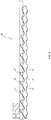
- Figure 1 shows a perspective view of a coil 10 according to the invention according to one embodiment.
- the helix 10 comprises a radially outer profile which has a plurality of radially outer projections 12.
- the helix 10 runs around an imaginary longitudinal or helical axis 14 and has a drive profile which comprises a plurality of cutouts 16.
- the helix 10 shown comprises two helical gears, the drive profile containing six cutouts 16 along the length of one helical gear.
- Figure 2 shows a plan view along the helix axis 14 of the helix 10 Figure 1 .
- the recesses 16 are spaced apart by the length of a helical path along a strip of material that forms the helix 10 and are aligned in the direction of the helix axis 14, as in FIG Figure 2nd can be seen.
- the helix 10 can receive a drive (not shown) of a drive tool in the direction of the helix axis 14, wherein the drive engages in the cutouts 16 and, upon rotation about the helix axis 14, can transmit a torque to the helix 10.
- a drive engages in all six pairs of aligned recesses 16 torsion or change in shape of the helix is avoided or at least limited.
- FIG. 3 shows a profile strip 18 which is used to produce a threaded insert according to the invention around the helix 10 of FIG Figures 1 and 2nd can be wrapped.
- the profile band 18 is on an inner side with the profile 20 of an internal thread and on an opposite outer side with the profile 22 (cf. Figure 4 ) preformed of an external thread.
- the profile strip 18 can include through openings 24, at which the profile strip 18 is pierced by its radially outer projections 12 when it is wound onto the helix 10.
- Figure 4 shows a threaded insert 26 according to the invention, for the manufacture of which the profile strip 18 Figure 3 around the helix 10 of the Figures 1 and 2nd was wrapped. It can be seen that the radially outer projections 12 of the helix 10 penetrate the profiled strip 18 and form part of the external thread 28 of the threaded insert 26.
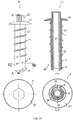
- Figure 5 shows a longitudinal section through the threaded insert 26 Figure 4 which comprises a threaded insert sleeve 30, which is formed or continued from the wound profile strip 18 and which comprises the helix 10.
- the winding pitch of the profile strip 18 in Figure 5 corresponds to the helix pitch and the through openings 24 are each provided in the area of the profile of the external thread, so that the external thread is formed or continued in this area by the radially outer projections 12. Because the helix pitch corresponds to the winding pitch and the radially outer projections 12 penetrate the profile strip in the region of the outer thread flank, the torque can be effectively transmitted from the helix 10 to the external thread 28 of the threaded insert sleeve 30.
- the pitch of the external thread 28 corresponds to the winding pitch of the profile strip, so that the external thread flank runs seamlessly along the external thread 28 and does not run over a transition on a lateral profile strip edge resulting from the winding.
- the Internal thread of the threaded insert sleeve 30 may have a different pitch than the external thread.
- the threaded insert sleeve 30 Since the helix 10, as in Figure 5 shown at a leading end (below in Figure 5 ) of the threaded insert sleeve 30, the threaded insert sleeve is drawn into the borehole from the leading end when it is introduced into a borehole.
- the internal thread of the threaded insert sleeve 30, which is located in the direction of the rear end of the threaded insert sleeve 30 from the helix 10 (top in Figure 5 ) can be used for anchoring an anchoring bolt that can be screwed into this threaded section.
- Figure 6 shows a plan view in the direction of the helix axis 14 of the threaded insert 26 of FIG Figures 4 and 5 .
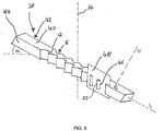
- Figure 7 shows a bolt 32 according to the invention according to one embodiment, which comprises a threaded section 34 with an external thread 28 and a helix 10 on a drive section 36.
- the pitch of the helix 10 corresponds to the pitch of the external thread 28 on the threaded portion 34.
- the radially outer projections 12 of the coil 10 are superimposed with an imaginary periodic continuation of the external thread 28 in the direction of the leading end of the bolt, so that the coil 10 for the subsequent one External thread 28 of the bolt 32 can form a thread that offers hardly any resistance to the external thread 28 when the bolt 32 is screwed in and in which the external thread 28 can engage.
- a material which is not suitable for furrowing in particular a non-hardened and / or corrosion-resistant material, can be used for that part of the bolt 32 which does not comprise the helix 10 and which is anchored in a borehole via a thread which is furrowed by the helix 10 can.
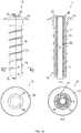
- Figure 8 shows a strip of material 38 that can be used to produce a coil 10, for which purpose the strip of material 38 is wound around an imaginary coil axis 14.
- the height of the projections 12 decreases in a direction of the material strip 38.
- this direction corresponds to the leading end of the coil 10, so that the diameter of the envelope of the coil produced from the material strip 38 decreases in the direction of the leading end of the coil.
- Such a helix 10 facilitates the application in a borehole and simplifies it the thread grooving.
- the area marked by lines in FIG. 1 from the material strip 38 consists of high-speed steel (HSS, High Speed Steel).
- the remaining part of the material strip can consist of stainless steel, for example.
- the method includes providing a strip of material 38 that is shown in FIG Figure 9 is shown.
- the material strip 38 extends in a longitudinal direction L and has an upper surface 40 and an opposite lower surface, the surface normal N of the upper surface 40 being at least approximately perpendicular to the longitudinal direction L.
- the material strip 38 also has a first side surface 42 and an opposite second side surface 44, the first side surface 42 containing a plurality of recesses 16 and the second side surface 44 containing a plurality of projections 12.
- the cutouts and / or the projections are introduced into the material strip 38 with the inclination of a spiral pitch to be wound.
- the spiral pitch to be wound, with which the material strip 38 is wound around the imaginary spiral axis 14, is in Figure 9 characterized by the angle ⁇ , which corresponds to the inclination between the helix axis 14 and the surface normal N.
- the imaginary cutting lines 46 of a cut between the first side surface 42 and / or the second side surface 44 with an imaginary cutting plane 48, which is spanned by the longitudinal direction L and the surface normal N, with an inclination that is at least approximately the one to be wound Helix pitch ⁇ corresponds to the surface normal N inclined.
- the method according to the invention further comprises winding the material strip 38 provided with the helix pitch ⁇ to be wound around an imaginary helix axis 14 to form a helix 10.
- the first side surface 42 in the drive profile runs in the longitudinal direction of the helix 10 parallel to the helix axis 14. This allows a drive to be used for the helix 10, the drive means of which run parallel to a longitudinal direction, this drive in the direction of the Helix axis 14 can be included in the drive profile of the helix 10, that the drive means evenly on the first side surface 42 of the material strip wound to the helix 10 38 concerns. This improves the stabilization of the helix 10 and the torque transmission.
- the second side surface 44 runs in the longitudinal direction of the helix 10 parallel to the helix axis 14. This can result in the radially outer projections 12 being perpendicular to the helix axis 14 and not inclined with the helix pitch ⁇ , radially Extend outwards so that the thread is not grooved but perpendicular to the wall of the borehole and evenly over the grooved edges 50 then running parallel to the helix axis 14.
- the radially outer projections 12 can also be tapered in the radial direction, for example as in FIG Figure 1 shown. In this case, the radially outer projections 12 do not have groove edges 50, but groove tips.
- Figure 10 shows a side view, a longitudinal section and a plan view of a threaded insert 26, in which the threaded insert sleeve 30 is made of plastic.
- a top section 52 is arranged at the upper, ie rear end of the threaded insert sleeve 30.
- a helix 10 of the type shown in Figure 1 is injected into the plastic sleeve 30 at a lower, ie leading end in the illustration.
- the threaded insert sleeve 30 has an external thread 22, which is also made of plastic and is formed integrally with the sleeve 30. In the embodiment shown, the external thread 22 runs only over part of the length of the threaded insert sleeve 30.
- the projections 12 of the helix 10 lie on an imaginary periodic continuation of the thread 22.
- the external thread can also lie between the tips of the radial outer profile 12 of the helix 10 run (not shown) and only be interrupted by the tips of the radially outer profile 12 of the helix 10, similar to the threaded insert 26 of FIG Fig. 4 and 5 the case is.
- the threaded insert sleeve 30 has a cavity 24 through which a drive tool (not shown) can be inserted and received in the drive profile of the helix 10, so that the threaded insert 26 can be screwed into a base, whereby the projections 12 form a thread.
- a drive tool not shown
- the top view of Fig. 10 the cutouts 16 can be seen, which form the drive profile of the helix 10.
- the threaded insert 26 from Figure 10 can be used, for example, to attach roof insulation or the like to a surface, for example a concrete surface.
- the plastic sleeve 30 can be produced inexpensively, even in long lengths, for example in lengths of 30 cm, 40 cm, 50 cm or beyond.
- the threaded insert 26 from Figure 10 only with its leading section, namely with the section on which the thread 22 is formed, is to be screwed into the associated subsurface.
- the term "thread insert” is therefore to be understood broadly in the present disclosure and is not intended to suggest that the "insert" is inserted into the substrate over its entire length.
- Figure 11 shows a further threaded insert 26 with a threaded insert sleeve 30 made of plastic, at the leading end in turn a helix 12 is injected in the manner described above.
- the plastic sleeve 30 has an external thread 28 which extends over the entire length of the plastic sleeve 30 and which is periodically continued by the projections 12 of the helix 10, as in FIG Figure 11 can be seen.
- the threaded insert 26 of Figure 11 has a drive element 56 that is permanently arranged in the plastic sleeve 30. At its portion near the leading end, the drive element 56 has a first profile 58, which can be clearly seen in the sectional view BB. This first profile 58 is in engagement with the drive profile of the helix 10.
- the drive element 56 has a second profile 60, which can be clearly seen in particular in the top view.
- the shape of the second profile corresponds to the first profile in this embodiment, but has a somewhat larger cross section because it is encapsulated with plastic.
- the second profile 60 can be brought into engagement with a drive tool.
- the threaded insert 26 from Figure 11 can therefore be screwed in more easily than that of Fig. 10 , because only a suitable drive tool needs to be attached to the top of the second profile 60, and an elongated tool does not have to be guided through the entire cavity 54 of the plastic sleeve 30.
- the threaded insert 26 is also from Figure 11 completely closed.
- the drive member 56 is hollow to save material and weight.
- the drive element 56 can be formed from a metallic material which gives the threaded insert 26 a comparatively high tensile strength and at the same time permits the transmission of a torque from the second profile 60 via the first profile 58 to the helix 12.
- the drive element can also consist of a reinforced plastic, in particular a plastic reinforced with short or long fibers, the fibers being able to be formed, for example, by carbon fibers or glass fibers.
- the drive element 56 can be made of a reinforced plastic, which is produced in an extrusion process by the meter and then cut to the appropriate length.
- Figure 12 shows a further threaded insert 26, the threaded insert of Figure 11 is very similar and will not be described again in detail.
- the main difference compared to the thread insert from Figure 11 consists in that the second profile 60 of the drive element 56 protrudes only slightly above the head section 52. Instead, the head section 52 has a recess 62 in which the second profile 60 of the drive element 52 is arranged, as can be seen particularly well in the plan view.
- the recess 62 is sufficiently large to allow the second profile 60 to be brought into engagement with a suitable drive tool (not shown).
- FIG. 13 a bolt 64 with a head 66 designed as a force application and a shaft section 68 on which a thread 22 is formed.
- the bolt 64 from Figure 13 is designed as a plastic injection molded part, ie the head 66, the shaft 68 and the thread 22 are made of plastic.
- a helix 10 of the in Figure 1 injected type shown At the leading end of the shaft 68 is a helix 10 of the in Figure 1 injected type shown, such that the radially outer profile, namely the projections 12, projects radially beyond the shaft portion 68 and is arranged on an imaginary periodic continuation of the thread 22.
- the injected coil 10 can have all the properties of the coil 10 described above, alone or in combination. However, it is not necessary for the helix 10 to have a drive profile, ie cutouts 16 (see Figure 1 ), since in this case the helix 10 should not take up a separate drive tool or drive element. Instead, it is completely injected into the shaft 68, since in this case the shaft is solid.
- the bolt 64 in Figure 13 has the advantage that it can be manufactured extremely inexpensively.
- the plastic material is also corrosion-resistant. At the same time, this allows radial outer profile 12 of the helix 10, which periodically continues the thread 22 so that the bolt 64 is self-tapping, even in hard ground, for example concrete or masonry.
Landscapes
- Engineering & Computer Science (AREA)
- General Engineering & Computer Science (AREA)
- Mechanical Engineering (AREA)
- Joining Of Building Structures In Genera (AREA)
- Hand Tools For Fitting Together And Separating, Or Other Hand Tools (AREA)
- Dowels (AREA)
- Injection Moulding Of Plastics Or The Like (AREA)
Applications Claiming Priority (3)
| Application Number | Priority Date | Filing Date | Title |
|---|---|---|---|
| DE102013109987.4A DE102013109987B4 (de) | 2013-09-11 | 2013-09-11 | Wendel für einen Gewindeeinsatz |
| PCT/EP2014/066899 WO2015036182A1 (fr) | 2013-09-11 | 2014-08-06 | Hélice pour insert fileté |
| EP14747673.3A EP3044468B1 (fr) | 2013-09-11 | 2014-08-06 | Hélice pour insert fileté |
Related Parent Applications (2)
| Application Number | Title | Priority Date | Filing Date |
|---|---|---|---|
| EP14747673.3A Division EP3044468B1 (fr) | 2013-09-11 | 2014-08-06 | Hélice pour insert fileté |
| EP14747673.3A Division-Into EP3044468B1 (fr) | 2013-09-11 | 2014-08-06 | Hélice pour insert fileté |
Publications (3)
| Publication Number | Publication Date |
|---|---|
| EP3663596A1 true EP3663596A1 (fr) | 2020-06-10 |
| EP3663596C0 EP3663596C0 (fr) | 2023-06-07 |
| EP3663596B1 EP3663596B1 (fr) | 2023-06-07 |
Family
ID=51266350
Family Applications (2)
| Application Number | Title | Priority Date | Filing Date |
|---|---|---|---|
| EP19218992.6A Active EP3663596B1 (fr) | 2013-09-11 | 2014-08-06 | Boulon avec une hélice pour taraudage d'un filet |
| EP14747673.3A Active EP3044468B1 (fr) | 2013-09-11 | 2014-08-06 | Hélice pour insert fileté |
Family Applications After (1)
| Application Number | Title | Priority Date | Filing Date |
|---|---|---|---|
| EP14747673.3A Active EP3044468B1 (fr) | 2013-09-11 | 2014-08-06 | Hélice pour insert fileté |
Country Status (7)
| Country | Link |
|---|---|
| US (1) | US10233957B2 (fr) |
| EP (2) | EP3663596B1 (fr) |
| CA (1) | CA2922875C (fr) |
| DE (1) | DE102013109987B4 (fr) |
| ES (2) | ES2818579T3 (fr) |
| PL (2) | PL3044468T3 (fr) |
| WO (1) | WO2015036182A1 (fr) |
Families Citing this family (13)
| Publication number | Priority date | Publication date | Assignee | Title |
|---|---|---|---|---|
| US10506897B2 (en) | 2016-03-04 | 2019-12-17 | Shorefield Holdings, LLC | Mixing assembly for mixing a product |
| USD814850S1 (en) * | 2016-03-04 | 2018-04-10 | Shorefield Holdings, LLC | Mixer |
| US10486121B2 (en) | 2016-03-04 | 2019-11-26 | Shorefield Holdings, LLC | Mixing assembly for mixing a product |
| EP3219442B1 (fr) | 2016-03-17 | 2022-01-19 | Ludwig Hettich Holding GmbH & Co. KG | Élement d'entrainement d'un couple de rotation sur une cosse a insert filete |
| DE102016125201A1 (de) | 2016-12-21 | 2018-06-21 | Ludwig Hettich Holding Gmbh & Co. Kg | System zum Fügen oder Armieren von Bauteilen |
| US11378120B2 (en) | 2017-05-08 | 2022-07-05 | Partnership Twello B.V. | Self-tapping screw |
| USD929799S1 (en) * | 2018-05-04 | 2021-09-07 | Buss Ag | Screw shaft element |
| US10935067B2 (en) | 2018-08-21 | 2021-03-02 | Max Gripp Anchors, Llc | Reverse-thread insert anchor for masonry applications |
| EP3736458A1 (fr) * | 2019-05-06 | 2020-11-11 | Hilti Aktiengesellschaft | Vis extensible comportant des doigts d'expansion séparés |
| DE102020108557A1 (de) * | 2019-08-08 | 2021-02-11 | Ludwig Hettich Holding Gmbh & Co. Kg | System zum Befestigen eines Ankers in einem mineralischen Untergrund |
| US11930912B2 (en) * | 2020-05-15 | 2024-03-19 | Brome Bird Care Inc. | Molded screw |
| DE102020210002A1 (de) * | 2020-08-06 | 2022-02-10 | Ims-Verbindungstechnik Gmbh & Co. Kg | Verbindungsmittel und Anordnung mit einem Werkstück und einem Verbindungsmittel |
| EP4467823A1 (fr) * | 2023-05-26 | 2024-11-27 | Hilti Aktiengesellschaft | Vis comprenant des dentelures de racine et de crête |
Citations (1)
| Publication number | Priority date | Publication date | Assignee | Title |
|---|---|---|---|---|
| WO2011063138A1 (fr) * | 2009-11-18 | 2011-05-26 | Simpson Strong-Tie Company, Inc. | Elément de fixation doté de filets trempés |
Family Cites Families (15)
| Publication number | Priority date | Publication date | Assignee | Title |
|---|---|---|---|---|
| US240780A (en) * | 1881-04-26 | smith | ||
| BE460113A (fr) * | 1944-06-01 | |||
| US3086072A (en) * | 1959-03-31 | 1963-04-16 | Formar Ind Inc | Non-conductive fasteners |
| US2993950A (en) * | 1959-06-17 | 1961-07-25 | Formar Ind Inc | Self-tapping non-conductive fastener |
| DE1216027B (de) * | 1963-03-29 | 1966-05-05 | Fritz Kirchhoff | Kopfschraube aus Kunststoff |
| WO1982000505A1 (fr) | 1980-08-11 | 1982-02-18 | Moyland J Steengracht | Vis tubulaires et procedes de penetration dans des materiaux en utilisant ces vis tubulaires |
| GB2271159B (en) * | 1992-09-04 | 1995-05-10 | Multiclip Co Ltd | Securing devices |
| EP0905389A3 (fr) * | 1997-09-25 | 2000-05-10 | TOGE-Dübel A. Gerhard KG | Vis pour l'ancrage dans du béton |
| US5961266A (en) | 1998-06-11 | 1999-10-05 | Tseng; Shao-Chien | Anti-vibration bolt and nut structure |
| JP3163073B2 (ja) * | 1998-09-18 | 2001-05-08 | 株式会社加藤スプリング製作所 | 取り外し可能タング付きインサート |
| DE19944217A1 (de) | 1999-09-15 | 2001-03-22 | Adolf Wuerth Gmbh & Co Kg | Bolzenanker |
| DE102006003172A1 (de) * | 2006-01-23 | 2007-07-26 | Ludwig Hettich & Co. | Schraubanker |
| DE102007042977A1 (de) | 2007-09-10 | 2009-04-23 | Ludwig Hettich & Co. | Schraubanker zum Befestigen von Anbauteilen in Beton oder Mauerwerk |
| DE102007054798B3 (de) | 2007-11-16 | 2009-04-16 | Ludwig Hettich & Co. | Verfahren zum Herstellen eines Gewindeeinsatzes mit Innen- und Außengewinde und Gewindeeinsatz |
| US8105004B2 (en) * | 2008-08-21 | 2012-01-31 | Robert Stephen | Hybrid composite-metal male fasteners |
-
2013
- 2013-09-11 DE DE102013109987.4A patent/DE102013109987B4/de active Active
-
2014
- 2014-08-06 ES ES14747673T patent/ES2818579T3/es active Active
- 2014-08-06 EP EP19218992.6A patent/EP3663596B1/fr active Active
- 2014-08-06 ES ES19218992T patent/ES2955507T3/es active Active
- 2014-08-06 EP EP14747673.3A patent/EP3044468B1/fr active Active
- 2014-08-06 PL PL14747673T patent/PL3044468T3/pl unknown
- 2014-08-06 PL PL19218992.6T patent/PL3663596T3/pl unknown
- 2014-08-06 WO PCT/EP2014/066899 patent/WO2015036182A1/fr not_active Ceased
- 2014-08-06 US US15/021,396 patent/US10233957B2/en active Active
- 2014-08-06 CA CA2922875A patent/CA2922875C/fr active Active
Patent Citations (1)
| Publication number | Priority date | Publication date | Assignee | Title |
|---|---|---|---|---|
| WO2011063138A1 (fr) * | 2009-11-18 | 2011-05-26 | Simpson Strong-Tie Company, Inc. | Elément de fixation doté de filets trempés |
Also Published As
| Publication number | Publication date |
|---|---|
| DE102013109987A1 (de) | 2015-03-12 |
| WO2015036182A1 (fr) | 2015-03-19 |
| EP3044468A1 (fr) | 2016-07-20 |
| US10233957B2 (en) | 2019-03-19 |
| ES2818579T3 (es) | 2021-04-13 |
| PL3663596T3 (pl) | 2023-10-16 |
| ES2955507T3 (es) | 2023-12-04 |
| CA2922875C (fr) | 2022-07-05 |
| EP3663596C0 (fr) | 2023-06-07 |
| US20160223006A1 (en) | 2016-08-04 |
| CA2922875A1 (fr) | 2015-03-19 |
| PL3044468T3 (pl) | 2021-02-08 |
| EP3663596B1 (fr) | 2023-06-07 |
| EP3044468B1 (fr) | 2020-06-24 |
| DE102013109987B4 (de) | 2017-03-23 |
Similar Documents
| Publication | Publication Date | Title |
|---|---|---|
| EP3044468B1 (fr) | Hélice pour insert fileté | |
| EP2257714B1 (fr) | Vis taraudeuse | |
| EP2893203B1 (fr) | Vis formant un trou et un taraudage pour le vissage direct de pièces sans pré-percer ainsi qu'assemblage de pièces ainsi réalisé | |
| DE102010043769B4 (de) | Ankerbaugruppe, insbesondere für den Berg- und Tunnelbau | |
| EP3040563B1 (fr) | Vis avec une discontinuité sur une section de filetage intermédiaire | |
| EP2185829A2 (fr) | Vis d'ancrage servant à fixer des éléments rapportés dans du béton ou dans un ouvrage de maçonnerie | |
| EP3097313B1 (fr) | Vis, système de fixation et utilisation d'une vis | |
| EP1754894B1 (fr) | Elément de connexion à ajustement serré et sa méthode de fabrication | |
| EP3219442B1 (fr) | Élement d'entrainement d'un couple de rotation sur une cosse a insert filete | |
| EP3374649B1 (fr) | Vis autotaraudeuse | |
| EP1512875A1 (fr) | Dispositif de raccordement pour un raccordement concret et bois | |
| DE102010043765B4 (de) | Ankerbaugruppe sowie Verfahren zur Herstellung einer Ankerbaugruppe | |
| EP2354572A1 (fr) | Vis autotaraudeuse | |
| DE102014000894A1 (de) | Verfahren zum Herstellen einer Befestigungsanordnung, Befestigungsanordnung und dafür vorgesehene Schraube | |
| DE102016105622B4 (de) | Verfahren zur Herstellung eines Schraubankers mit einem metrischen Anschlussgewinde | |
| DE102020108566A1 (de) | System zum Befestigen eines Ankers in einem mineralischen Untergrund | |
| EP4212743A1 (fr) | Élément d'ancrage destiné à être ancré dans un puits de forage, ensemble d'ancrage comprenant un tel élément d'ancrage et procédé de fabrication d'un tel ensemble d'ancrage | |
| EP4166797A1 (fr) | Dispositif d'ancrage et procédé d'ancrage d'un élément d'ancrage dans un matériau | |
| DE102009044287A1 (de) | Schraube und Verfahren zu ihrer Herstellung | |
| DE102020103370A1 (de) | Schraube und Verfahren zu deren Herstellung | |
| EP2189668A1 (fr) | Vis autoperceuse |
Legal Events
| Date | Code | Title | Description |
|---|---|---|---|
| PUAI | Public reference made under article 153(3) epc to a published international application that has entered the european phase |
Free format text: ORIGINAL CODE: 0009012 |
|
| STAA | Information on the status of an ep patent application or granted ep patent |
Free format text: STATUS: THE APPLICATION HAS BEEN PUBLISHED |
|
| AC | Divisional application: reference to earlier application |
Ref document number: 3044468 Country of ref document: EP Kind code of ref document: P |
|
| AK | Designated contracting states |
Kind code of ref document: A1 Designated state(s): AL AT BE BG CH CY CZ DE DK EE ES FI FR GB GR HR HU IE IS IT LI LT LU LV MC MK MT NL NO PL PT RO RS SE SI SK SM TR |
|
| STAA | Information on the status of an ep patent application or granted ep patent |
Free format text: STATUS: REQUEST FOR EXAMINATION WAS MADE |
|
| 17P | Request for examination filed |
Effective date: 20201210 |
|
| RBV | Designated contracting states (corrected) |
Designated state(s): AL AT BE BG CH CY CZ DE DK EE ES FI FR GB GR HR HU IE IS IT LI LT LU LV MC MK MT NL NO PL PT RO RS SE SI SK SM TR |
|
| RIC1 | Information provided on ipc code assigned before grant |
Ipc: F16B 25/00 20060101ALI20220729BHEP Ipc: F16B 37/12 20060101ALI20220729BHEP Ipc: F16B 33/00 20060101AFI20220729BHEP |
|
| GRAP | Despatch of communication of intention to grant a patent |
Free format text: ORIGINAL CODE: EPIDOSNIGR1 |
|
| STAA | Information on the status of an ep patent application or granted ep patent |
Free format text: STATUS: GRANT OF PATENT IS INTENDED |
|
| INTG | Intention to grant announced |
Effective date: 20220930 |
|
| GRAS | Grant fee paid |
Free format text: ORIGINAL CODE: EPIDOSNIGR3 |
|
| GRAA | (expected) grant |
Free format text: ORIGINAL CODE: 0009210 |
|
| STAA | Information on the status of an ep patent application or granted ep patent |
Free format text: STATUS: THE PATENT HAS BEEN GRANTED |
|
| AC | Divisional application: reference to earlier application |
Ref document number: 3044468 Country of ref document: EP Kind code of ref document: P |
|
| AK | Designated contracting states |
Kind code of ref document: B1 Designated state(s): AL AT BE BG CH CY CZ DE DK EE ES FI FR GB GR HR HU IE IS IT LI LT LU LV MC MK MT NL NO PL PT RO RS SE SI SK SM TR |
|
| REG | Reference to a national code |
Ref country code: GB Ref legal event code: FG4D Free format text: NOT ENGLISH |
|
| REG | Reference to a national code |
Ref country code: CH Ref legal event code: EP Ref country code: AT Ref legal event code: REF Ref document number: 1575900 Country of ref document: AT Kind code of ref document: T Effective date: 20230615 Ref country code: DE Ref legal event code: R096 Ref document number: 502014016603 Country of ref document: DE |
|
| P01 | Opt-out of the competence of the unified patent court (upc) registered |
Effective date: 20230524 |
|
| U01 | Request for unitary effect filed |
Effective date: 20230630 |
|
| U07 | Unitary effect registered |
Designated state(s): AT BE BG DE DK EE FI FR IT LT LU LV MT NL PT SE SI Effective date: 20230708 |
|
| P04 | Withdrawal of opt-out of the competence of the unified patent court (upc) registered |
Effective date: 20230705 |
|
| REG | Reference to a national code |
Ref country code: LT Ref legal event code: MG9D |
|
| U20 | Renewal fee for the european patent with unitary effect paid |
Year of fee payment: 10 Effective date: 20230828 |
|
| REG | Reference to a national code |
Ref country code: NO Ref legal event code: T2 Effective date: 20230607 |
|
| PGFP | Annual fee paid to national office [announced via postgrant information from national office to epo] |
Ref country code: TR Payment date: 20230828 Year of fee payment: 10 Ref country code: NO Payment date: 20230818 Year of fee payment: 10 Ref country code: ES Payment date: 20230913 Year of fee payment: 10 |
|
| PG25 | Lapsed in a contracting state [announced via postgrant information from national office to epo] |
Ref country code: RS Free format text: LAPSE BECAUSE OF FAILURE TO SUBMIT A TRANSLATION OF THE DESCRIPTION OR TO PAY THE FEE WITHIN THE PRESCRIBED TIME-LIMIT Effective date: 20230607 Ref country code: HR Free format text: LAPSE BECAUSE OF FAILURE TO SUBMIT A TRANSLATION OF THE DESCRIPTION OR TO PAY THE FEE WITHIN THE PRESCRIBED TIME-LIMIT Effective date: 20230607 Ref country code: GR Free format text: LAPSE BECAUSE OF FAILURE TO SUBMIT A TRANSLATION OF THE DESCRIPTION OR TO PAY THE FEE WITHIN THE PRESCRIBED TIME-LIMIT Effective date: 20230908 |
|
| PGFP | Annual fee paid to national office [announced via postgrant information from national office to epo] |
Ref country code: PL Payment date: 20230807 Year of fee payment: 10 |
|
| REG | Reference to a national code |
Ref country code: ES Ref legal event code: FG2A Ref document number: 2955507 Country of ref document: ES Kind code of ref document: T3 Effective date: 20231204 |
|
| PG25 | Lapsed in a contracting state [announced via postgrant information from national office to epo] |
Ref country code: SK Free format text: LAPSE BECAUSE OF FAILURE TO SUBMIT A TRANSLATION OF THE DESCRIPTION OR TO PAY THE FEE WITHIN THE PRESCRIBED TIME-LIMIT Effective date: 20230607 |
|
| PG25 | Lapsed in a contracting state [announced via postgrant information from national office to epo] |
Ref country code: IS Free format text: LAPSE BECAUSE OF FAILURE TO SUBMIT A TRANSLATION OF THE DESCRIPTION OR TO PAY THE FEE WITHIN THE PRESCRIBED TIME-LIMIT Effective date: 20231007 |
|
| PG25 | Lapsed in a contracting state [announced via postgrant information from national office to epo] |
Ref country code: SM Free format text: LAPSE BECAUSE OF FAILURE TO SUBMIT A TRANSLATION OF THE DESCRIPTION OR TO PAY THE FEE WITHIN THE PRESCRIBED TIME-LIMIT Effective date: 20230607 Ref country code: SK Free format text: LAPSE BECAUSE OF FAILURE TO SUBMIT A TRANSLATION OF THE DESCRIPTION OR TO PAY THE FEE WITHIN THE PRESCRIBED TIME-LIMIT Effective date: 20230607 Ref country code: RO Free format text: LAPSE BECAUSE OF FAILURE TO SUBMIT A TRANSLATION OF THE DESCRIPTION OR TO PAY THE FEE WITHIN THE PRESCRIBED TIME-LIMIT Effective date: 20230607 Ref country code: IS Free format text: LAPSE BECAUSE OF FAILURE TO SUBMIT A TRANSLATION OF THE DESCRIPTION OR TO PAY THE FEE WITHIN THE PRESCRIBED TIME-LIMIT Effective date: 20231007 Ref country code: CZ Free format text: LAPSE BECAUSE OF FAILURE TO SUBMIT A TRANSLATION OF THE DESCRIPTION OR TO PAY THE FEE WITHIN THE PRESCRIBED TIME-LIMIT Effective date: 20230607 |
|
| REG | Reference to a national code |
Ref country code: DE Ref legal event code: R097 Ref document number: 502014016603 Country of ref document: DE |
|
| PG25 | Lapsed in a contracting state [announced via postgrant information from national office to epo] |
Ref country code: MC Free format text: LAPSE BECAUSE OF FAILURE TO SUBMIT A TRANSLATION OF THE DESCRIPTION OR TO PAY THE FEE WITHIN THE PRESCRIBED TIME-LIMIT Effective date: 20230607 |
|
| PG25 | Lapsed in a contracting state [announced via postgrant information from national office to epo] |
Ref country code: MC Free format text: LAPSE BECAUSE OF FAILURE TO SUBMIT A TRANSLATION OF THE DESCRIPTION OR TO PAY THE FEE WITHIN THE PRESCRIBED TIME-LIMIT Effective date: 20230607 |
|
| PLBE | No opposition filed within time limit |
Free format text: ORIGINAL CODE: 0009261 |
|
| STAA | Information on the status of an ep patent application or granted ep patent |
Free format text: STATUS: NO OPPOSITION FILED WITHIN TIME LIMIT |
|
| 26N | No opposition filed |
Effective date: 20240308 |
|
| REG | Reference to a national code |
Ref country code: IE Ref legal event code: MM4A |
|
| PG25 | Lapsed in a contracting state [announced via postgrant information from national office to epo] |
Ref country code: IE Free format text: LAPSE BECAUSE OF NON-PAYMENT OF DUE FEES Effective date: 20230806 |
|
| PG25 | Lapsed in a contracting state [announced via postgrant information from national office to epo] |
Ref country code: IE Free format text: LAPSE BECAUSE OF NON-PAYMENT OF DUE FEES Effective date: 20230806 |
|
| U20 | Renewal fee for the european patent with unitary effect paid |
Year of fee payment: 11 Effective date: 20240826 |
|
| P05 | Withdrawal of opt-out of the competence of the unified patent court (upc) changed |
Free format text: CASE NUMBER: APP_545621/2023 Effective date: 20230708 |
|
| PG25 | Lapsed in a contracting state [announced via postgrant information from national office to epo] |
Ref country code: NO Free format text: LAPSE BECAUSE OF NON-PAYMENT OF DUE FEES Effective date: 20240831 |
|
| PG25 | Lapsed in a contracting state [announced via postgrant information from national office to epo] |
Ref country code: CY Free format text: LAPSE BECAUSE OF FAILURE TO SUBMIT A TRANSLATION OF THE DESCRIPTION OR TO PAY THE FEE WITHIN THE PRESCRIBED TIME-LIMIT; INVALID AB INITIO Effective date: 20140806 |
|
| PG25 | Lapsed in a contracting state [announced via postgrant information from national office to epo] |
Ref country code: HU Free format text: LAPSE BECAUSE OF FAILURE TO SUBMIT A TRANSLATION OF THE DESCRIPTION OR TO PAY THE FEE WITHIN THE PRESCRIBED TIME-LIMIT; INVALID AB INITIO Effective date: 20140806 |
|
| REG | Reference to a national code |
Ref country code: ES Ref legal event code: FD2A Effective date: 20250926 |
|
| U20 | Renewal fee for the european patent with unitary effect paid |
Year of fee payment: 12 Effective date: 20250825 |
|
| PG25 | Lapsed in a contracting state [announced via postgrant information from national office to epo] |
Ref country code: ES Free format text: LAPSE BECAUSE OF NON-PAYMENT OF DUE FEES Effective date: 20240807 |
|
| PGFP | Annual fee paid to national office [announced via postgrant information from national office to epo] |
Ref country code: GB Payment date: 20250826 Year of fee payment: 12 |
|
| PGFP | Annual fee paid to national office [announced via postgrant information from national office to epo] |
Ref country code: CH Payment date: 20250901 Year of fee payment: 12 |
|
| PG25 | Lapsed in a contracting state [announced via postgrant information from national office to epo] |
Ref country code: PL Free format text: LAPSE BECAUSE OF NON-PAYMENT OF DUE FEES Effective date: 20240806 |