EP3663703A1 - Tête militaire perforante - Google Patents
Tête militaire perforante Download PDFInfo
- Publication number
- EP3663703A1 EP3663703A1 EP19208948.0A EP19208948A EP3663703A1 EP 3663703 A1 EP3663703 A1 EP 3663703A1 EP 19208948 A EP19208948 A EP 19208948A EP 3663703 A1 EP3663703 A1 EP 3663703A1
- Authority
- EP
- European Patent Office
- Prior art keywords
- bar
- military
- energetic material
- flanges
- head according
- Prior art date
- Legal status (The legal status is an assumption and is not a legal conclusion. Google has not performed a legal analysis and makes no representation as to the accuracy of the status listed.)
- Granted
Links
Images

Classifications
-
- F—MECHANICAL ENGINEERING; LIGHTING; HEATING; WEAPONS; BLASTING
- F42—AMMUNITION; BLASTING
- F42B—EXPLOSIVE CHARGES, e.g. FOR BLASTING, FIREWORKS, AMMUNITION
- F42B12/00—Projectiles, missiles or mines characterised by the warhead, the intended effect, or the material
- F42B12/02—Projectiles, missiles or mines characterised by the warhead, the intended effect, or the material characterised by the warhead or the intended effect
- F42B12/04—Projectiles, missiles or mines characterised by the warhead, the intended effect, or the material characterised by the warhead or the intended effect of armour-piercing type
- F42B12/06—Projectiles, missiles or mines characterised by the warhead, the intended effect, or the material characterised by the warhead or the intended effect of armour-piercing type with hard or heavy core; Kinetic energy penetrators
-
- F—MECHANICAL ENGINEERING; LIGHTING; HEATING; WEAPONS; BLASTING
- F42—AMMUNITION; BLASTING
- F42B—EXPLOSIVE CHARGES, e.g. FOR BLASTING, FIREWORKS, AMMUNITION
- F42B12/00—Projectiles, missiles or mines characterised by the warhead, the intended effect, or the material
- F42B12/02—Projectiles, missiles or mines characterised by the warhead, the intended effect, or the material characterised by the warhead or the intended effect
- F42B12/20—Projectiles, missiles or mines characterised by the warhead, the intended effect, or the material characterised by the warhead or the intended effect of high-explosive type
- F42B12/201—Projectiles, missiles or mines characterised by the warhead, the intended effect, or the material characterised by the warhead or the intended effect of high-explosive type characterised by target class
- F42B12/204—Projectiles, missiles or mines characterised by the warhead, the intended effect, or the material characterised by the warhead or the intended effect of high-explosive type characterised by target class for attacking structures, e.g. specific buildings or fortifications, ships or vehicles
-
- F—MECHANICAL ENGINEERING; LIGHTING; HEATING; WEAPONS; BLASTING
- F42—AMMUNITION; BLASTING
- F42B—EXPLOSIVE CHARGES, e.g. FOR BLASTING, FIREWORKS, AMMUNITION
- F42B12/00—Projectiles, missiles or mines characterised by the warhead, the intended effect, or the material
- F42B12/02—Projectiles, missiles or mines characterised by the warhead, the intended effect, or the material characterised by the warhead or the intended effect
- F42B12/20—Projectiles, missiles or mines characterised by the warhead, the intended effect, or the material characterised by the warhead or the intended effect of high-explosive type
- F42B12/207—Projectiles, missiles or mines characterised by the warhead, the intended effect, or the material characterised by the warhead or the intended effect of high-explosive type characterised by the explosive material or the construction of the high explosive warhead, e.g. insensitive ammunition
-
- F—MECHANICAL ENGINEERING; LIGHTING; HEATING; WEAPONS; BLASTING
- F42—AMMUNITION; BLASTING
- F42B—EXPLOSIVE CHARGES, e.g. FOR BLASTING, FIREWORKS, AMMUNITION
- F42B12/00—Projectiles, missiles or mines characterised by the warhead, the intended effect, or the material
- F42B12/02—Projectiles, missiles or mines characterised by the warhead, the intended effect, or the material characterised by the warhead or the intended effect
- F42B12/36—Projectiles, missiles or mines characterised by the warhead, the intended effect, or the material characterised by the warhead or the intended effect for dispensing materials; for producing chemical or physical reaction; for signalling ; for transmitting information
- F42B12/46—Projectiles, missiles or mines characterised by the warhead, the intended effect, or the material characterised by the warhead or the intended effect for dispensing materials; for producing chemical or physical reaction; for signalling ; for transmitting information for dispensing gases, vapours, powders or chemically-reactive substances
- F42B12/50—Projectiles, missiles or mines characterised by the warhead, the intended effect, or the material characterised by the warhead or the intended effect for dispensing materials; for producing chemical or physical reaction; for signalling ; for transmitting information for dispensing gases, vapours, powders or chemically-reactive substances by dispersion
- F42B12/52—Fuel-air explosive devices
-
- F—MECHANICAL ENGINEERING; LIGHTING; HEATING; WEAPONS; BLASTING
- F42—AMMUNITION; BLASTING
- F42C—AMMUNITION FUZES; ARMING OR SAFETY MEANS THEREFOR
- F42C19/00—Details of fuzes
- F42C19/08—Primers; Detonators
- F42C19/0838—Primers or igniters for the initiation or the explosive charge in a warhead
- F42C19/0846—Arrangements of a multiplicity of primers or detonators, dispersed within a warhead, for increased efficiency
Definitions
- the technical field of the invention is that of piercing military heads which comprise a bar surrounded at least in part by at least one energetic material.
- the subject of the invention is a perforating military head comprising a perforating bar surrounded at least in part by at least one energetic material, and comprising a means for initiating energetic material, a military head characterized in that the bar is integral with two flanges, a front flange and a rear flange, the bar extending in front of the front flange, the flanges and the bar delimiting an annular volume in which is placed the energetic material (s), military head comprising a cylindrical envelope surrounding the energetic material (s), the envelope being constituted by a thin sheet of synthetic material or else by an explosive material with thermosetting plastic binder integrating in its composition glass or carbon fibers.
- the energetic material may be a material with thermobaric effect.
- the piercing military head may include a cylindrical envelope surrounding the energetic material (s).
- the envelope may consist of a thin sheet of synthetic material.
- the energetic material may comprise a secondary explosive incorporating a breath-reinforcing agent, such as aluminum or ammonium perchlorate.
- a breath-reinforcing agent such as aluminum or ammonium perchlorate.
- the priming means may then comprise at least one ring of detonation relays secured to at least one of the flanges.
- the energetic material may comprise a combustible dispersible gel in air.
- the energetic material may be a gel combining a fuel such as nitromethane and at least one breath-enhancing material such as aluminum.
- the initiating means may include at least one initiating explosive ring interposed between the bar and the energetic material, which ring is initiated by at least one ring of initiators.
- the bar and the flanges can be made in the form of a single piece.
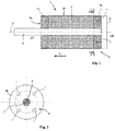
- a military head 1 according to a first embodiment of the invention, comprises a perforating bar 2 which is integral with two flanges 3a and 3b.
- the bar 2 is for example made of a dense material such as tungsten.
- the function of the bar 2 is to ensure the perforation of a wall of a target (not shown).
- the military head 1 is secured to a projectile (not shown) such as a missile or a rocket, or even a projectile fired by a weapon system (tank or artillery gun).
- a projectile such as a missile or a rocket
- a weapon system such as a weapon or artillery gun
- the projectile is driven by a speed V which is communicated to it by the weapon system or else by a propellant (missile or rocket).
- This speed V is that at which the bar impacts a wall of which it provides the perforation.
- the flanges 3a and 3b are made integral with the bar 2, for example by threading or welding if the bar and the closing flange are made of different materials (for reasons of mass gain or positioning of the center of gravity. .).
- the flanges can also, in the case of using an additive manufacturing process, form only one and only part with the bar. They are then made of a single material ensuring the mechanical strength of the military head to the constraints of implementation (shooting in particular) while also ensuring the terminal performance relating to the perforation of reinforced structures.
- the flanges are for example made in steel with high mechanical characteristics (elastic limit higher than 1800 Mega Pascals). It is clear to those skilled in the art that it is also possible to produce the bar and the flanges in a single piece by a conventional machining process by removing material.
- the bar 2 extends in front AV of the front flange 3a. It is the bar which impacts the target wall first.
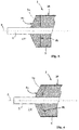
- the front flange 3a may also have an ogive profile favoring the continuation of the perforation initiated by the bar 2. Such a variant profile is visible on the figures 3 and 4 .
- the front face 4a of the front flange 3a is conical and the rear face 4b is flat.
- This massive front flange has good perforation characteristics.
- the front face 4a of the front flange 3a is conical and the rear face 4b is also conical. This last embodiment makes it possible to reduce the mass of the front flange.
- the flanges 3a and 3b and the bar 2 define an annular volume in which is disposed at least one energetic material 5.
- the rear flange 3b carries an initiating means 6 of the energetic material 5.
- This priming means 6 here comprises at least one ring of detonation relay 7 which are integral with the rear flange 3b and which are arranged in housings adapted to receive them. All the detonation relays 7 are controlled by a rocket 8 which ensures their simultaneous initiation and to which they are connected by wires.
- the detonation relays 7 are regularly distributed angularly around the axis 9 of the military head.
- Multipoint ignition of energetic material 5 generates a wave of pseudo-annular detonation (the shape of which depends on the number of relays 7 integrated into the priming system) in the material 5, without disturbance by the bar 2.
- the military head finally comprises a cylindrical envelope 10 which surrounds the energetic material 5 and also the flanges 3a and 3b.
- the material of the envelope 10 may consist of a thin sheet of synthetic material, for example a sheet of polytetra-fluorethylene or of heat-shrinkable polyvinylidene fluoride, or a plastic material reinforced with glass fiber.
- the casing 10 seals the energy charge 5 against moisture. It does not intervene in the mechanical resistance of the military head 1 which is provided by the bar 2 and the flanges 3a and 3b (and also by the structure of the projectile - not shown).
- the casing 10 could advantageously consist of a material which is itself explosive with a thermosetting plastic binder which will provide the necessary seal.
- This envelope of energetic material will integrate in its composition glass or carbon fibers which will optimize its rigidity. Consequently, the envelope, far from disturbing the generation of the expected breath effects, will itself contribute to this generation.
- the military head 1 thus generates only a blast effect, which decreases the radius of lethality of the ammunition during an initiation in an open field and limits the collateral effects when used in urban areas.
- the military head according to the invention has a perforation capacity which is provided to it by the bar 2, possibly supplemented by the front flange 3a.
- the rocket 8 initiates the energetic material 5.
- the latter is configured to generate a blast effect. This effect is deployed behind the protective wall crossed by the bar. Efficiency is therefore optimal inside a confined space which was protected by the wall thus crossed.
- the energetic material 5 will thus be a material with a thermobaric effect, that is to say a material optimized to generate a blast effect.
- the energetic material 5 may comprise a secondary explosive, for example hexogen, which incorporates a breath-reinforcing agent, such as aluminum or ammonium perchlorate. Most breath enhancers are powerful reducers.
- an energetic material comprising 30 to 40% of hexogen, 20 to 30% of trinitrotoluene and 30 to 40% of aluminum.
- the figure 5 shows in longitudinal section a military head according to a second embodiment of the invention.
- This mode differs from the previous one essentially by the nature of the energetic material 5 which is used.
- the energetic material 5 here consists of a dispersible gel which is combustible in the air. These materials are well known to those skilled in the art under the Anglo-Saxon name of "explosive fuel-air” or FAE.
- the energetic material 5 could thus consist of a gel which combines a combustible material such as nitromethane and a breath-enhancing material such as aluminum.
- Such a sequence is obtained by using a ring of ignition and projection explosive 11 which is interposed between the bar 2 and the energetic material 5.
- This explosive ring 11 is itself initiated by a ring of initiators 7 controlled by the rocket 8.
- the ignition and projection explosive ring 11 is for example formed by a block of hexogen or octogen associated with phlegmatizing binders.
- An energetic material for example with pyrophoric effect, can be incorporated into the ignition ring 11 to improve the ignition capabilities of the gel by the ignition and projection explosive 11 after the gel has been sprayed.
- the detonation of the explosive ring 11 will cause the radial projection of the thermobaric energetic material 5 in the form of droplets, so that the apparent surface of the cloud formed by the droplets is as large as possible.
- This distribution of droplets will optimize their ignition conditions in suspension and will amplify the effects of aerobic afterburning (reaction mechanisms associated with the use of all or part of the oxygen in the ambient air). The associated breath is maximized.
- the energy deployed during the dispersion causes the ignition of the fuel included in the droplets step by step.
- the energetic material is formed of a stack of several annular blocks surrounding the bar and interposed between the two flanges.
- a military head comprising two detonation relay crowns. It is possible to provide two concentric rings arranged at the level of only one of the flanges. It is also possible to provide at least one detonation relay ring integral with each of the flanges. All the crowns will be connected to the rocket which will ensure their initiation. It is also possible to associate at least one ring of detonation relays on each flange with a ring of initiating explosive allowing the dispersion and initiation of a dispersible and combustible gel.
Landscapes
- Engineering & Computer Science (AREA)
- General Engineering & Computer Science (AREA)
- Chemical & Material Sciences (AREA)
- Combustion & Propulsion (AREA)
- Dispersion Chemistry (AREA)
- Aiming, Guidance, Guns With A Light Source, Armor, Camouflage, And Targets (AREA)
- Specific Sealing Or Ventilating Devices For Doors And Windows (AREA)
- Table Equipment (AREA)
- Pressure Welding/Diffusion-Bonding (AREA)
Abstract
Description
- Le domaine technique de l'invention est celui des têtes militaires perforantes qui comprennent un barreau entouré au moins en partie d'au moins un matériau énergétique.
- Il a été proposé en particulier par le brevet
US3302570 un projectile comprenant un barreau perforant, par exemple en alliage de tungstène, entouré par une composition incendiaire qui est elle-même entourée par un corps de projectile dont la partie avant permet d'améliorer la perforation d'une cible. - Un tel projectile a des capacités tout à la fois perforante et incendiaire. Cependant la quantité de matériau énergétique emportée reste modeste et l'effet de souffle obtenu est très limité.
- On connait également par le brevet
US6135028 un projectile ayant deux modes de fonctionnement : un mode perforant qui est assuré par un noyau renfermant une charge explosive et un mode anti cible légère qui est assuré par une enveloppe engendrant des éclats qui sont mis en vitesse par une couronne d'explosif. Avec ce projectile, la charge entourant le barreau est éjectée à l'impact d'une cible dure. Seul l'explosif contenu à l'intérieur du barreau peut être initié à l'intérieur de la cible. La masse d'explosif mis en œuvre reste donc réduite et l'effet de projection des éclats du barreau est privilégié par rapport à l'effet de souffle. - On connait aussi par le brevet
EP0886121 un projectile comportant une grenade perforante chargée d'explosif. Cette grenade est disposée axialement dans un étui qui génère des éclats et qui renferme également une charge explosive périphérique. Dans ce brevet, comme dans le précédent, seule la charge explosive contenue dans la grenade perforante peut être mise en œuvre à l'intérieur d'une cible. La masse d'explosif mis en œuvre reste donc réduite et l'effet de projection des éclats de la grenade est encore privilégié par rapport à l'effet de souffle. - Il existe aujourd'hui un besoin de définir des têtes militaires ayant une capacité perforante renforcée et pouvant engendrer un effet de souffle renforcé à l'intérieur d'une cible ou derrière une paroi.
- Ainsi l'invention a pour objet une tête militaire perforante comprenant un barreau perforant entouré au moins en partie d'au moins un matériau énergétique, et comportant un moyen d'amorçage du matériau énergétique, tête militaire caractérisée en ce que le barreau est solidaire de deux flasques, un flasque avant et un flasque arrière, le barreau s'étendant en avant du flasque avant, les flasques et le barreau délimitant un volume annulaire dans lequel est disposé le ou les matériau(x) énergétique(s), tête militaire comportant une enveloppe cylindrique entourant le ou les matériaux énergétiques, l'enveloppe étant constituée par une feuille mince en matériau synthétique ou bien par un matériau explosif à liant plastique thermodurcissable intégrant dans sa composition des fibres de verre ou de carbone.
- Avantageusement, le matériau énergétique pourra être un matériau à effet thermobarique.
- La tête militaire perforante pourra comporter une enveloppe cylindrique entourant le ou les matériaux énergétiques.
- L'enveloppe pourra être constituée par une feuille mince en matériau synthétique.
- Selon un mode de réalisation, le matériau énergétique pourra comprendre un explosif secondaire incorporant un agent renforçateur de souffle, tel que l'aluminium ou le perchlorate d'ammonium.
- Le moyen d'amorçage pourra alors comprendre au moins une couronne de relais de détonation solidaires d'au moins un des flasques.
- Selon un autre mode de réalisation, le matériau énergétique pourra comprendre un gel dispersable combustible dans l'air.
- Le matériau énergétique pourra être un gel associant un combustible tel que le nitrométhane et au moins un matériau renforçateur de souffle tel que l'aluminium.
- Le moyen d'amorçage pourra comprendre au moins un anneau d'explosif d'amorçage interposé entre le barreau et le matériau énergétique, anneau lui-même initié par au moins une couronne d'initiateurs.
- Selon un mode particulier de réalisation, le barreau et les flasques pourront être réalisés sous la forme d'une seule pièce.
- L'invention sera mieux comprise à la lecture de la description qui va suivre de différents modes de réalisation, description faite en référence aux dessins annexés et dans lesquels :
- [
Fig. 1 ] montre en coupe longitudinale une tête militaire selon un premier mode de réalisation de l'invention ; - [
Fig. 2 ] est une coupe transversale de cette tête militaire, suivant le plan dont la trace AA est repérée à lafigure 1 ; - [
Fig. 3 ] montre en coupe longitudinale une première variante d'exécution du flasque avant ; - [
Fig. 4 ] montre en coupe longitudinale une seconde variante d'exécution du flasque avant ; - [
Fig. 5 ] représente une tête militaire selon un deuxième mode de réalisation de l'invention. - En se reportant à la
figure 1 , une tête militaire 1 selon un premier mode de réalisation de l'invention, comprend un barreau 2 perforant qui est solidaire de deux flasques 3a et 3b. Le barreau 2 est par exemple réalisé en un matériau dense tel que le tungstène. - Il peut être également réalisé en acier à très hautes caractéristiques mécaniques (acier maraging). Pour ce dernier mode de réalisation, un procédé de fabrication additive (fusion laser) permettra notamment d'aboutir à une architecture monolithique combinant le barreau 2 et les deux flasques 3a,3b dans une seule et unique pièce, gage d'une optimisation de la tenue mécanique de l'ensemble.
- La fonction du barreau 2 est d'assurer la perforation d'une paroi d'une cible (non représentée).
- La tête militaire 1 est solidaire d'un projectile (non représenté) tel qu'un missile ou une roquette, ou encore un projectile tiré par un système d'arme (canon de char ou d'artillerie).
- Le projectile est animé d'une vitesse V qui lui est communiquée par le système d'arme ou bien par un propulseur (missile ou roquette). Cette vitesse V est celle à laquelle le barreau impacte une paroi dont il assure la perforation.
- Les flasques 3a et 3b sont rendus solidaires du barreau 2, par exemple par filetage ou par soudure si le barreau et le flasque de fermeture sont fabriqués dans des matériaux différents (pour des raisons de gain de masse ou de positionnement du centre de gravité...).
- A titre d'exemple, il est possible d'envisager un barreau en tungstène et un flasque en acier à haute résistance. Comme précisé précédemment, les flasques peuvent aussi, dans le cas du recours à un procédé de fabrication additive, ne former qu'une seule et unique pièce avec le barreau. Ils sont alors réalisés en un seul et même matériau assurant la tenue mécanique de la tête militaire aux contraintes de mise en œuvre (le tir en particulier) tout en assurant également les performances terminales relatives à la perforation de structures renforcées. Les flasques sont par exemple réalisés en acier à hautes caractéristiques mécaniques (limite élastique supérieure à 1800 Méga Pascals). Il est clair pour l'Homme du Métier qu'il est également possible de réaliser le barreau et les flasques en une seule et même pièce par un procédé d'usinage classique par enlèvement de matière.
- Comme on le voit sur la
figure 1 , le barreau 2 s'étend en avant AV du flasque avant 3a. C'est le barreau qui impacte la paroi de la cible en premier. Le flasque avant 3a pourra par ailleurs présenter un profil ogivé favorisant la poursuite de la perforation amorcée par le barreau 2. Une telle variante de profil est visible sur lesfigures 3 et 4 . - Sur la
figure 3 , la face avant 4a du flasque avant 3a est conique et la face arrière 4b est plane. Ce flasque avant massif a de bonnes caractéristiques de perforation. - Sur la
figure 4 , la face avant 4a du flasque avant 3a est conique et la face arrière 4b est également conique. Ce dernier mode de réalisation permet de réduire la masse du flasque avant. - Les flasques 3a et 3b et le barreau 2 délimitent un volume annulaire dans lequel est disposé au moins un matériau énergétique 5.
- Suivant le mode de réalisation des
figures 1 et 2 , le flasque arrière 3b porte un moyen d'amorçage 6 du matériau énergétique 5. - Ce moyen d'amorçage 6 comprend ici au moins une couronne de relais de détonation 7 qui sont solidaires du flasque arrière 3b et qui sont disposés dans des logements adaptés pour les recevoir. Tous les relais de détonation 7 sont commandés par une fusée 8 qui assure leur initiation simultanée et à laquelle ils sont reliés par des fils.
- Comme on le voit sur la
figure 2 , les relais de détonation 7 sont régulièrement répartis angulairement autour de l'axe 9 de la tête militaire. L'amorçage multipoints du matériau énergétique 5 assure la génération d'une onde de détonation pseudo-annulaire (dont la forme est fonction du nombre de relais 7 intégrés au système d'amorçage) dans le matériau 5, sans perturbation par le barreau 2. - La tête militaire comporte enfin une enveloppe cylindrique 10 qui entoure le matériau énergétique 5 et également les flasques 3a et 3b. Le matériau de l'enveloppe 10 pourra être constitué par une feuille mince en matériau synthétique, par exemple une feuille de polytétra-fluoréthylène ou de fluorure de polyvinylidène thermo rétractable, ou une matière plastique renforcée de fibre de verre.
- L'enveloppe 10 assure l'étanchéité du chargement énergétique 5 vis-à-vis de l'humidité. Elle n'intervient pas dans la résistance mécanique de la tête militaire 1 qui est assurée par le barreau 2 et les flasques 3a et 3b (et aussi par la structure du projectile - non représentée).
- Il serait bien entendu possible de mettre en œuvre une enveloppe 10 en aluminium. L'intérêt de choisir une enveloppe en un matériau synthétique mince est d'éviter la formation d'éclats lors de l'initiation du matériau 5. En effet, avec les projectiles classiques, l'énergie développée par l'explosif est en partie consommée par la fragmentation de l'enveloppe avant de permettre la projection des éclats. L'effet de souffle se trouve donc obligatoirement réduit.
- Dans une autre variante, l'enveloppe 10 pourra être avantageusement constituée par un matériau lui-même explosif à liant plastique thermodurcissable qui assurera l'étanchéité nécessaire. Cette enveloppe en matériau énergétique intégrera dans sa composition des fibres de verre ou de carbone qui permettront d'en optimiser la rigidité. Dès lors, l'enveloppe, loin de perturber la génération des effets de souffle attendus, contribuera elle-même à cette génération.
- La tête militaire 1 engendre ainsi uniquement un effet de souffle, ce qui diminue le rayon de létalité de la munition lors d'une initiation en champ ouvert et limite les effets collatéraux lors d'une utilisation en zone urbaine.
- Ainsi la tête militaire selon l'invention a une capacité de perforation qui lui est assurée par le barreau 2, complété éventuellement par le flasque avant 3a. Une fois la paroi de la cible perforée, la fusée 8 assure l'initiation du matériau énergétique 5. Ce dernier est configuré pour engendrer un effet de souffle. Cet effet est déployé derrière la paroi de protection traversée par le barreau. L'efficacité est donc optimale à l'intérieur d'un espace confiné qui était protégé par la paroi ainsi traversée.
- Il n'y a pas de projection d'éclats. Une initiation de la tête militaire 1 à l'extérieur de la cible aura un effet létal réduit.
- Le matériau énergétique 5 sera ainsi un matériau à effet thermobarique, c'est-à-dire un matériau optimisé pour engendrer un effet de souffle.
- Selon un mode de réalisation, le matériau énergétique 5 pourra comprendre un explosif secondaire, par exemple de l'hexogène, qui incorpore un agent renforçateur de souffle, tel que l'aluminium ou le perchlorate d'ammonium. La plupart des agents renforçateurs de souffle sont des réducteurs puissants.
- A titre d'exemple on pourra associer :
40% à 50% d'hexogène, 30% à 40% d'aluminium et 10 à 20% de perchlorate d'ammonium en poudre et éventuellement un liant. - On pourra également mettre en œuvre un matériau énergétique comprenant 30 à 40% d'hexogène, 20 à 30% de trinitrotoluène et 30 à 40% d'aluminium.
- La
figure 5 représente en coupe longitudinale une tête militaire selon un deuxième mode de réalisation de l'invention. - Ce mode diffère du précédent essentiellement par la nature du matériau énergétique 5 qui est mis en œuvre.
- Le matériau énergétique 5 est ici constitué par un gel dispersable qui est combustible dans l'air. Ces matériaux sont bien connus de l'Homme du Métier sous la dénomination anglo saxonne de « fuel-air explosives » ou FAE.
- Le matériau énergétique 5 pourra ainsi être constitué par un gel qui associe un matériau combustible tel que le nitrométhane et un matériau renforçateur de souffle tel que l'aluminium.
- La mise en œuvre d'un tel matériau nécessite tout d'abord une dispersion du gel sous forme de fines gouttelettes, puis un allumage du gel ainsi dispersé.
- On obtient une telle séquence en utilisant un anneau d'explosif d'allumage et de projection 11 qui est interposé entre le barreau 2 et le matériau énergétique 5.
- Cet anneau d'explosif 11 est lui-même initié par une couronne d'initiateurs 7 commandés par la fusée 8.
- L'anneau d'explosif d'allumage et de projection 11 est par exemple formé par un bloc d'hexogène ou d'octogène associé à des liants flegmatisants. On pourra incorporer dans l'anneau d'allumage 11 un matériau énergétique, par exemple à effet pyrophorique, pour améliorer les capacités d'allumage du gel par l'explosif d'allumage et de projection 11 après la projection du gel.
- La mise en détonation de l'anneau explosif 11 va provoquer la projection radiale du matériau énergétique thermobarique 5 sous forme de gouttelettes, de telle sorte que la surface apparente du nuage formé par les gouttelettes soit la plus importante possible.
- Cette répartition des gouttelettes permettra d'optimiser leurs conditions d'allumage en suspension et amplifiera les effets de postcombustion aérobie (mécanismes réactionnels associés à l'utilisation de tout ou partie de l'oxygène de l'air ambiant). Le souffle associé s'en retrouve maximisé.
- En parallèle l'énergie déployée lors de la dispersion provoque l'allumage de proche en proche du combustible compris dans les gouttelettes.
- Il en résulte un effet de souffle qui pourra être renforcé par la présence de réducteurs forts dans le gel, tel que la poudre d'aluminium.
- A titre d'exemple on pourra associer :
50% à 60% de nitrométhane et 30% à 40% d'aluminium en poudre (granulométrie de l'ordre du micromètre). - A titre de variante, il est possible également de définir une tête militaire selon l'invention et dans laquelle le matériau énergétique est formé d'un empilement de plusieurs blocs annulaires entourant le barreau et interposés entre les deux flasques.
- On pourra aussi définir une tête militaire comportant deux couronnes de relais de détonation. On pourra prévoir deux couronnes concentriques disposées au niveau d'un seul des flasques. On pourra également prévoir au moins une couronne de relais de détonation solidaire de chacun des flasques. Toutes les couronnes seront reliées à la fusée qui assurera leur initiation. On pourra également associer au moins une couronne de relais de détonation sur chaque flasque avec un anneau d'explosif d'amorçage permettant la dispersion et l'initiation d'un gel dispersable et combustible.
Claims (8)
- Tête militaire perforante (1) comprenant un barreau perforant (2) entouré au moins en partie d'au moins un matériau énergétique (5), et comportant un moyen d'amorçage (6) du matériau énergétique, tête militaire caractérisée en ce que le barreau (2) est solidaire de deux flasques (3a,3b), un flasque avant (3a) et un flasque arrière (3b), le barreau (2) s'étendant en avant du flasque avant (3a), les flasques (3a, 3b) et le barreau (2) délimitant un volume annulaire dans lequel est disposé le ou les matériau(x) énergétique(s) (5), tête militaire comportant une enveloppe cylindrique (10) entourant le ou les matériaux énergétiques (5), l'enveloppe (10) étant constituée par une feuille mince en matériau synthétique ou bien par un matériau explosif à liant plastique thermodurcissable intégrant dans sa composition des fibres de verre ou de carbone.
- Tête militaire perforante selon la revendication 1, caractérisée en ce que le matériau énergétique (5) est un matériau à effet thermobarique.
- Tête militaire perforante selon une des revendications 1 ou 2, caractérisée en ce que le matériau énergétique (5) comprend un explosif secondaire incorporant un agent renforçateur de souffle, tel que l'aluminium ou le perchlorate d'ammonium.
- Tête militaire perforante selon la revendication 3, caractérisée en ce que le moyen d'amorçage (6) comprend au moins une couronne de relais de détonation (7) solidaires d'au moins un des flasques (3a,3b).
- Tête militaire perforante selon une des revendications 1 ou 2, caractérisée en ce que le matériau énergétique (5) comprend un gel dispersable combustible dans l'air.
- Tête militaire perforante selon la revendication 5, caractérisée en ce que le matériau énergétique (5) est un gel associant un combustible tel que le nitrométhane et au moins un matériau renforçateur de souffle tel que l'aluminium.
- Tête militaire perforante selon une des revendications 5 ou 6, caractérisée en ce que le moyen d'amorçage (6) comprend au moins un anneau d'explosif d'amorçage (11) interposé entre le barreau (2) et le matériau énergétique (5), anneau (11) lui-même initié par au moins une couronne d'initiateurs (7).
- Tête militaire perforante selon une des revendications 1 à 7, caractérisée en ce que le barreau (2) et les flasques (3a,3b) sont réalisés sous la forme d'une seule pièce.
Applications Claiming Priority (1)
| Application Number | Priority Date | Filing Date | Title |
|---|---|---|---|
| FR1872415A FR3089621B1 (fr) | 2018-12-07 | 2018-12-07 | Tete militaire perforante |
Publications (2)
| Publication Number | Publication Date |
|---|---|
| EP3663703A1 true EP3663703A1 (fr) | 2020-06-10 |
| EP3663703B1 EP3663703B1 (fr) | 2022-05-04 |
Family
ID=66049319
Family Applications (1)
| Application Number | Title | Priority Date | Filing Date |
|---|---|---|---|
| EP19208948.0A Active EP3663703B1 (fr) | 2018-12-07 | 2019-11-13 | Tête militaire perforante |
Country Status (3)
| Country | Link |
|---|---|
| EP (1) | EP3663703B1 (fr) |
| ES (1) | ES2920801T3 (fr) |
| FR (1) | FR3089621B1 (fr) |
Cited By (1)
| Publication number | Priority date | Publication date | Assignee | Title |
|---|---|---|---|---|
| CN113063325A (zh) * | 2021-03-15 | 2021-07-02 | 中国人民解放军93213部队 | 一种核事故应急空中作用装置 |
Citations (7)
| Publication number | Priority date | Publication date | Assignee | Title |
|---|---|---|---|---|
| US3000308A (en) * | 1956-03-07 | 1961-09-19 | William E Land | High explosive composition |
| US3302570A (en) | 1965-07-23 | 1967-02-07 | Walter G Finch | Armor piercing, fragmenting and incendiary projectile |
| US4573412A (en) * | 1984-04-27 | 1986-03-04 | The United States Of America As Represented By The Secretary Of The Army | Plug nozzle kinetic energy penetrator rocket |
| EP0886121A2 (fr) | 1997-06-13 | 1998-12-23 | Diehl Stiftung & Co. | Projectile pour une arme à feu à canon tubulaire |
| US6135028A (en) | 1998-10-14 | 2000-10-24 | The United States Of America As Represented By The Secretary Of The Navy | Penetrating dual-mode warhead |
| US20060011053A1 (en) * | 2002-02-21 | 2006-01-19 | Rheinmetall W & M Gmbh | Method for producing a large-caliber, high-explosive projectile, and high-explosive projectile produced in accordance with the method |
| US20060060273A1 (en) * | 2004-05-06 | 2006-03-23 | Kjell-Tore Smith | Pressable explosive composition |
-
2018
- 2018-12-07 FR FR1872415A patent/FR3089621B1/fr active Active
-
2019
- 2019-11-13 EP EP19208948.0A patent/EP3663703B1/fr active Active
- 2019-11-13 ES ES19208948T patent/ES2920801T3/es active Active
Patent Citations (7)
| Publication number | Priority date | Publication date | Assignee | Title |
|---|---|---|---|---|
| US3000308A (en) * | 1956-03-07 | 1961-09-19 | William E Land | High explosive composition |
| US3302570A (en) | 1965-07-23 | 1967-02-07 | Walter G Finch | Armor piercing, fragmenting and incendiary projectile |
| US4573412A (en) * | 1984-04-27 | 1986-03-04 | The United States Of America As Represented By The Secretary Of The Army | Plug nozzle kinetic energy penetrator rocket |
| EP0886121A2 (fr) | 1997-06-13 | 1998-12-23 | Diehl Stiftung & Co. | Projectile pour une arme à feu à canon tubulaire |
| US6135028A (en) | 1998-10-14 | 2000-10-24 | The United States Of America As Represented By The Secretary Of The Navy | Penetrating dual-mode warhead |
| US20060011053A1 (en) * | 2002-02-21 | 2006-01-19 | Rheinmetall W & M Gmbh | Method for producing a large-caliber, high-explosive projectile, and high-explosive projectile produced in accordance with the method |
| US20060060273A1 (en) * | 2004-05-06 | 2006-03-23 | Kjell-Tore Smith | Pressable explosive composition |
Non-Patent Citations (1)
| Title |
|---|
| VADHE P P ET AL: "Cast aluminized explosives (review)", COMBUSTION, EXPLOSION, AND SHOCK WAVES, KLUWER ACADEMIC PUBLISHERS-PLENUM PUBLISHERS, NE, vol. 44, no. 4, 11 September 2008 (2008-09-11), pages 461 - 477, XP019601613, ISSN: 1573-8345 * |
Cited By (1)
| Publication number | Priority date | Publication date | Assignee | Title |
|---|---|---|---|---|
| CN113063325A (zh) * | 2021-03-15 | 2021-07-02 | 中国人民解放军93213部队 | 一种核事故应急空中作用装置 |
Also Published As
| Publication number | Publication date |
|---|---|
| ES2920801T3 (es) | 2022-08-09 |
| FR3089621A1 (fr) | 2020-06-12 |
| EP3663703B1 (fr) | 2022-05-04 |
| FR3089621B1 (fr) | 2022-04-01 |
Similar Documents
| Publication | Publication Date | Title |
|---|---|---|
| US8443731B1 (en) | Reactive material enhanced projectiles, devices for generating reactive material enhanced projectiles and related methods | |
| EP2923171B1 (fr) | Projectile gyrostabilise projetant une charge utile | |
| FR2867555A1 (fr) | Projectiles a matiere reactive renforces, et procedes relatifs a ces projectiles | |
| EP0694755B1 (fr) | Projectile explosif | |
| EP1659359B1 (fr) | Munition ou composant de munition comprenant un matériau énergétique structural | |
| EP3663703B1 (fr) | Tête militaire perforante | |
| US7980178B1 (en) | Environmentally friendly percussion primer | |
| US12454929B1 (en) | Rocket motor including an embedded charge assembly (ECA) configured to support a burn rate enhancement (BRE) wire | |
| FR2552869A1 (fr) | Tete militaire a charges creuses a sequence | |
| EP2372296B1 (fr) | Pénétrateur à énergie cinétique | |
| FR2993355A1 (fr) | Munition a rayon de letalite reduit et procede de fabrication d'une telle munition | |
| EP0193427B1 (fr) | Tête militaire à charges formées montées en tandem | |
| EP1302741B1 (fr) | Munition explosive | |
| EP0664433B1 (fr) | Projectile de perforation et munition équipée d'un tel dispositif | |
| FR2966582A1 (fr) | Charge formee multimodes | |
| EP1099926B1 (fr) | Charge militaire duale, pour missile surface air, contre cibles conventionnelles et missiles balistiques tactiques | |
| US20260055746A1 (en) | Rocket motor with dual embedded burnable cutting explosive energetic material | |
| EP1269105B1 (fr) | Charge pyrotechnique a fonctionnement dual | |
| FR2978238A1 (fr) | Munition a rayon de letalite reduit | |
| FR2517424A1 (fr) | Piege a balle pour grenade a fusil | |
| EP0943887A1 (fr) | Dispositif de conversion permettant d'obtenir un obus perforant anti structures bétonnées à partir d'un obus explosif et obus perforant obtenu avec un tel dispositif | |
| EP1870640B1 (fr) | Tête militaire engendrant un noyau tubulaire | |
| FR2742539A1 (fr) | Charge explosive a usages multiples, notamment charge de deminage | |
| FR3013826A1 (fr) | Munition a letalite reduite | |
| EP1988355A1 (fr) | Projectile générateur d'éclats |
Legal Events
| Date | Code | Title | Description |
|---|---|---|---|
| PUAI | Public reference made under article 153(3) epc to a published international application that has entered the european phase |
Free format text: ORIGINAL CODE: 0009012 |
|
| STAA | Information on the status of an ep patent application or granted ep patent |
Free format text: STATUS: THE APPLICATION HAS BEEN PUBLISHED |
|
| AK | Designated contracting states |
Kind code of ref document: A1 Designated state(s): AL AT BE BG CH CY CZ DE DK EE ES FI FR GB GR HR HU IE IS IT LI LT LU LV MC MK MT NL NO PL PT RO RS SE SI SK SM TR |
|
| AX | Request for extension of the european patent |
Extension state: BA ME |
|
| STAA | Information on the status of an ep patent application or granted ep patent |
Free format text: STATUS: REQUEST FOR EXAMINATION WAS MADE |
|
| 17P | Request for examination filed |
Effective date: 20201209 |
|
| RBV | Designated contracting states (corrected) |
Designated state(s): AL AT BE BG CH CY CZ DE DK EE ES FI FR GB GR HR HU IE IS IT LI LT LU LV MC MK MT NL NO PL PT RO RS SE SI SK SM TR |
|
| GRAP | Despatch of communication of intention to grant a patent |
Free format text: ORIGINAL CODE: EPIDOSNIGR1 |
|
| STAA | Information on the status of an ep patent application or granted ep patent |
Free format text: STATUS: GRANT OF PATENT IS INTENDED |
|
| INTG | Intention to grant announced |
Effective date: 20220112 |
|
| GRAS | Grant fee paid |
Free format text: ORIGINAL CODE: EPIDOSNIGR3 |
|
| GRAA | (expected) grant |
Free format text: ORIGINAL CODE: 0009210 |
|
| STAA | Information on the status of an ep patent application or granted ep patent |
Free format text: STATUS: THE PATENT HAS BEEN GRANTED |
|
| AK | Designated contracting states |
Kind code of ref document: B1 Designated state(s): AL AT BE BG CH CY CZ DE DK EE ES FI FR GB GR HR HU IE IS IT LI LT LU LV MC MK MT NL NO PL PT RO RS SE SI SK SM TR |
|
| REG | Reference to a national code |
Ref country code: GB Ref legal event code: FG4D Free format text: NOT ENGLISH |
|
| REG | Reference to a national code |
Ref country code: CH Ref legal event code: EP |
|
| REG | Reference to a national code |
Ref country code: AT Ref legal event code: REF Ref document number: 1489477 Country of ref document: AT Kind code of ref document: T Effective date: 20220515 |
|
| REG | Reference to a national code |
Ref country code: IE Ref legal event code: FG4D Free format text: LANGUAGE OF EP DOCUMENT: FRENCH Ref country code: DE Ref legal event code: R096 Ref document number: 602019014420 Country of ref document: DE |
|
| REG | Reference to a national code |
Ref country code: SE Ref legal event code: TRGR |
|
| REG | Reference to a national code |
Ref country code: ES Ref legal event code: FG2A Ref document number: 2920801 Country of ref document: ES Kind code of ref document: T3 Effective date: 20220809 |
|
| REG | Reference to a national code |
Ref country code: LT Ref legal event code: MG9D |
|
| REG | Reference to a national code |
Ref country code: NO Ref legal event code: T2 Effective date: 20220504 |
|
| REG | Reference to a national code |
Ref country code: NL Ref legal event code: MP Effective date: 20220504 |
|
| REG | Reference to a national code |
Ref country code: AT Ref legal event code: MK05 Ref document number: 1489477 Country of ref document: AT Kind code of ref document: T Effective date: 20220504 |
|
| PG25 | Lapsed in a contracting state [announced via postgrant information from national office to epo] |
Ref country code: PT Free format text: LAPSE BECAUSE OF FAILURE TO SUBMIT A TRANSLATION OF THE DESCRIPTION OR TO PAY THE FEE WITHIN THE PRESCRIBED TIME-LIMIT Effective date: 20220905 Ref country code: NL Free format text: LAPSE BECAUSE OF FAILURE TO SUBMIT A TRANSLATION OF THE DESCRIPTION OR TO PAY THE FEE WITHIN THE PRESCRIBED TIME-LIMIT Effective date: 20220504 Ref country code: LT Free format text: LAPSE BECAUSE OF FAILURE TO SUBMIT A TRANSLATION OF THE DESCRIPTION OR TO PAY THE FEE WITHIN THE PRESCRIBED TIME-LIMIT Effective date: 20220504 Ref country code: HR Free format text: LAPSE BECAUSE OF FAILURE TO SUBMIT A TRANSLATION OF THE DESCRIPTION OR TO PAY THE FEE WITHIN THE PRESCRIBED TIME-LIMIT Effective date: 20220504 Ref country code: GR Free format text: LAPSE BECAUSE OF FAILURE TO SUBMIT A TRANSLATION OF THE DESCRIPTION OR TO PAY THE FEE WITHIN THE PRESCRIBED TIME-LIMIT Effective date: 20220805 Ref country code: FI Free format text: LAPSE BECAUSE OF FAILURE TO SUBMIT A TRANSLATION OF THE DESCRIPTION OR TO PAY THE FEE WITHIN THE PRESCRIBED TIME-LIMIT Effective date: 20220504 Ref country code: BG Free format text: LAPSE BECAUSE OF FAILURE TO SUBMIT A TRANSLATION OF THE DESCRIPTION OR TO PAY THE FEE WITHIN THE PRESCRIBED TIME-LIMIT Effective date: 20220804 Ref country code: AT Free format text: LAPSE BECAUSE OF FAILURE TO SUBMIT A TRANSLATION OF THE DESCRIPTION OR TO PAY THE FEE WITHIN THE PRESCRIBED TIME-LIMIT Effective date: 20220504 |
|
| PG25 | Lapsed in a contracting state [announced via postgrant information from national office to epo] |
Ref country code: RS Free format text: LAPSE BECAUSE OF FAILURE TO SUBMIT A TRANSLATION OF THE DESCRIPTION OR TO PAY THE FEE WITHIN THE PRESCRIBED TIME-LIMIT Effective date: 20220504 Ref country code: PL Free format text: LAPSE BECAUSE OF FAILURE TO SUBMIT A TRANSLATION OF THE DESCRIPTION OR TO PAY THE FEE WITHIN THE PRESCRIBED TIME-LIMIT Effective date: 20220504 Ref country code: LV Free format text: LAPSE BECAUSE OF FAILURE TO SUBMIT A TRANSLATION OF THE DESCRIPTION OR TO PAY THE FEE WITHIN THE PRESCRIBED TIME-LIMIT Effective date: 20220504 Ref country code: IS Free format text: LAPSE BECAUSE OF FAILURE TO SUBMIT A TRANSLATION OF THE DESCRIPTION OR TO PAY THE FEE WITHIN THE PRESCRIBED TIME-LIMIT Effective date: 20220904 |
|
| PG25 | Lapsed in a contracting state [announced via postgrant information from national office to epo] |
Ref country code: SM Free format text: LAPSE BECAUSE OF FAILURE TO SUBMIT A TRANSLATION OF THE DESCRIPTION OR TO PAY THE FEE WITHIN THE PRESCRIBED TIME-LIMIT Effective date: 20220504 Ref country code: SK Free format text: LAPSE BECAUSE OF FAILURE TO SUBMIT A TRANSLATION OF THE DESCRIPTION OR TO PAY THE FEE WITHIN THE PRESCRIBED TIME-LIMIT Effective date: 20220504 Ref country code: RO Free format text: LAPSE BECAUSE OF FAILURE TO SUBMIT A TRANSLATION OF THE DESCRIPTION OR TO PAY THE FEE WITHIN THE PRESCRIBED TIME-LIMIT Effective date: 20220504 Ref country code: EE Free format text: LAPSE BECAUSE OF FAILURE TO SUBMIT A TRANSLATION OF THE DESCRIPTION OR TO PAY THE FEE WITHIN THE PRESCRIBED TIME-LIMIT Effective date: 20220504 Ref country code: DK Free format text: LAPSE BECAUSE OF FAILURE TO SUBMIT A TRANSLATION OF THE DESCRIPTION OR TO PAY THE FEE WITHIN THE PRESCRIBED TIME-LIMIT Effective date: 20220504 Ref country code: CZ Free format text: LAPSE BECAUSE OF FAILURE TO SUBMIT A TRANSLATION OF THE DESCRIPTION OR TO PAY THE FEE WITHIN THE PRESCRIBED TIME-LIMIT Effective date: 20220504 |
|
| REG | Reference to a national code |
Ref country code: DE Ref legal event code: R097 Ref document number: 602019014420 Country of ref document: DE |
|
| PLBE | No opposition filed within time limit |
Free format text: ORIGINAL CODE: 0009261 |
|
| STAA | Information on the status of an ep patent application or granted ep patent |
Free format text: STATUS: NO OPPOSITION FILED WITHIN TIME LIMIT |
|
| PG25 | Lapsed in a contracting state [announced via postgrant information from national office to epo] |
Ref country code: AL Free format text: LAPSE BECAUSE OF FAILURE TO SUBMIT A TRANSLATION OF THE DESCRIPTION OR TO PAY THE FEE WITHIN THE PRESCRIBED TIME-LIMIT Effective date: 20220504 |
|
| 26N | No opposition filed |
Effective date: 20230207 |
|
| PG25 | Lapsed in a contracting state [announced via postgrant information from national office to epo] |
Ref country code: SI Free format text: LAPSE BECAUSE OF FAILURE TO SUBMIT A TRANSLATION OF THE DESCRIPTION OR TO PAY THE FEE WITHIN THE PRESCRIBED TIME-LIMIT Effective date: 20220504 |
|
| PG25 | Lapsed in a contracting state [announced via postgrant information from national office to epo] |
Ref country code: MC Free format text: LAPSE BECAUSE OF FAILURE TO SUBMIT A TRANSLATION OF THE DESCRIPTION OR TO PAY THE FEE WITHIN THE PRESCRIBED TIME-LIMIT Effective date: 20220504 |
|
| PG25 | Lapsed in a contracting state [announced via postgrant information from national office to epo] |
Ref country code: LU Free format text: LAPSE BECAUSE OF NON-PAYMENT OF DUE FEES Effective date: 20221113 |
|
| PG25 | Lapsed in a contracting state [announced via postgrant information from national office to epo] |
Ref country code: IE Free format text: LAPSE BECAUSE OF NON-PAYMENT OF DUE FEES Effective date: 20221113 |
|
| P01 | Opt-out of the competence of the unified patent court (upc) registered |
Effective date: 20231212 |
|
| PG25 | Lapsed in a contracting state [announced via postgrant information from national office to epo] |
Ref country code: HU Free format text: LAPSE BECAUSE OF FAILURE TO SUBMIT A TRANSLATION OF THE DESCRIPTION OR TO PAY THE FEE WITHIN THE PRESCRIBED TIME-LIMIT; INVALID AB INITIO Effective date: 20191113 |
|
| PG25 | Lapsed in a contracting state [announced via postgrant information from national office to epo] |
Ref country code: CY Free format text: LAPSE BECAUSE OF FAILURE TO SUBMIT A TRANSLATION OF THE DESCRIPTION OR TO PAY THE FEE WITHIN THE PRESCRIBED TIME-LIMIT Effective date: 20220504 |
|
| PG25 | Lapsed in a contracting state [announced via postgrant information from national office to epo] |
Ref country code: MK Free format text: LAPSE BECAUSE OF FAILURE TO SUBMIT A TRANSLATION OF THE DESCRIPTION OR TO PAY THE FEE WITHIN THE PRESCRIBED TIME-LIMIT Effective date: 20220504 |
|
| PG25 | Lapsed in a contracting state [announced via postgrant information from national office to epo] |
Ref country code: MT Free format text: LAPSE BECAUSE OF FAILURE TO SUBMIT A TRANSLATION OF THE DESCRIPTION OR TO PAY THE FEE WITHIN THE PRESCRIBED TIME-LIMIT Effective date: 20220504 |
|
| PG25 | Lapsed in a contracting state [announced via postgrant information from national office to epo] |
Ref country code: BG Free format text: LAPSE BECAUSE OF FAILURE TO SUBMIT A TRANSLATION OF THE DESCRIPTION OR TO PAY THE FEE WITHIN THE PRESCRIBED TIME-LIMIT Effective date: 20220504 |
|
| PG25 | Lapsed in a contracting state [announced via postgrant information from national office to epo] |
Ref country code: BG Free format text: LAPSE BECAUSE OF FAILURE TO SUBMIT A TRANSLATION OF THE DESCRIPTION OR TO PAY THE FEE WITHIN THE PRESCRIBED TIME-LIMIT Effective date: 20220504 |
|
| REG | Reference to a national code |
Ref country code: CH Ref legal event code: U11 Free format text: ST27 STATUS EVENT CODE: U-0-0-U10-U11 (AS PROVIDED BY THE NATIONAL OFFICE) Effective date: 20251201 |
|
| PGFP | Annual fee paid to national office [announced via postgrant information from national office to epo] |
Ref country code: DE Payment date: 20251022 Year of fee payment: 7 |
|
| PGFP | Annual fee paid to national office [announced via postgrant information from national office to epo] |
Ref country code: GB Payment date: 20251023 Year of fee payment: 7 |
|
| PGFP | Annual fee paid to national office [announced via postgrant information from national office to epo] |
Ref country code: NO Payment date: 20251024 Year of fee payment: 7 |
|
| PGFP | Annual fee paid to national office [announced via postgrant information from national office to epo] |
Ref country code: IT Payment date: 20251022 Year of fee payment: 7 |
|
| PGFP | Annual fee paid to national office [announced via postgrant information from national office to epo] |
Ref country code: FR Payment date: 20251022 Year of fee payment: 7 |
|
| PGFP | Annual fee paid to national office [announced via postgrant information from national office to epo] |
Ref country code: TR Payment date: 20251027 Year of fee payment: 7 Ref country code: BE Payment date: 20251022 Year of fee payment: 7 |
|
| PGFP | Annual fee paid to national office [announced via postgrant information from national office to epo] |
Ref country code: CH Payment date: 20251201 Year of fee payment: 7 Ref country code: SE Payment date: 20251022 Year of fee payment: 7 |
|
| PGFP | Annual fee paid to national office [announced via postgrant information from national office to epo] |
Ref country code: ES Payment date: 20251201 Year of fee payment: 7 |