EP3663715A1 - Winkel- und abstandsmessverfahren, verfahren zum zeichnen von trajektoriediagrammen und laserentfernungsmessungssystem - Google Patents
Winkel- und abstandsmessverfahren, verfahren zum zeichnen von trajektoriediagrammen und laserentfernungsmessungssystem Download PDFInfo
- Publication number
- EP3663715A1 EP3663715A1 EP18840199.6A EP18840199A EP3663715A1 EP 3663715 A1 EP3663715 A1 EP 3663715A1 EP 18840199 A EP18840199 A EP 18840199A EP 3663715 A1 EP3663715 A1 EP 3663715A1
- Authority
- EP
- European Patent Office
- Prior art keywords
- laser
- emitting device
- receiving device
- angle
- laser emitting
- Prior art date
- Legal status (The legal status is an assumption and is not a legal conclusion. Google has not performed a legal analysis and makes no representation as to the accuracy of the status listed.)
- Granted
Links
Images


Classifications
-
- G—PHYSICS
- G01—MEASURING; TESTING
- G01C—MEASURING DISTANCES, LEVELS OR BEARINGS; SURVEYING; NAVIGATION; GYROSCOPIC INSTRUMENTS; PHOTOGRAMMETRY OR VIDEOGRAMMETRY
- G01C15/00—Surveying instruments or accessories not provided for in groups G01C1/00 - G01C13/00
- G01C15/002—Active optical surveying means
-
- G—PHYSICS
- G01—MEASURING; TESTING
- G01B—MEASURING LENGTH, THICKNESS OR SIMILAR LINEAR DIMENSIONS; MEASURING ANGLES; MEASURING AREAS; MEASURING IRREGULARITIES OF SURFACES OR CONTOURS
- G01B11/00—Measuring arrangements characterised by the use of optical techniques
- G01B11/26—Measuring arrangements characterised by the use of optical techniques for measuring angles or tapers; for testing the alignment of axes
-
- G—PHYSICS
- G01—MEASURING; TESTING
- G01C—MEASURING DISTANCES, LEVELS OR BEARINGS; SURVEYING; NAVIGATION; GYROSCOPIC INSTRUMENTS; PHOTOGRAMMETRY OR VIDEOGRAMMETRY
- G01C1/00—Measuring angles
-
- G—PHYSICS
- G01—MEASURING; TESTING
- G01C—MEASURING DISTANCES, LEVELS OR BEARINGS; SURVEYING; NAVIGATION; GYROSCOPIC INSTRUMENTS; PHOTOGRAMMETRY OR VIDEOGRAMMETRY
- G01C15/00—Surveying instruments or accessories not provided for in groups G01C1/00 - G01C13/00
-
- G—PHYSICS
- G01—MEASURING; TESTING
- G01C—MEASURING DISTANCES, LEVELS OR BEARINGS; SURVEYING; NAVIGATION; GYROSCOPIC INSTRUMENTS; PHOTOGRAMMETRY OR VIDEOGRAMMETRY
- G01C15/00—Surveying instruments or accessories not provided for in groups G01C1/00 - G01C13/00
- G01C15/02—Means for marking measuring points
- G01C15/06—Surveyors' staffs; Movable markers
-
- G—PHYSICS
- G01—MEASURING; TESTING
- G01C—MEASURING DISTANCES, LEVELS OR BEARINGS; SURVEYING; NAVIGATION; GYROSCOPIC INSTRUMENTS; PHOTOGRAMMETRY OR VIDEOGRAMMETRY
- G01C3/00—Measuring distances in line of sight; Optical rangefinders
- G01C3/02—Details
- G01C3/06—Use of electric means to obtain final indication
- G01C3/08—Use of electric radiation detectors
-
- G—PHYSICS
- G01—MEASURING; TESTING
- G01S—RADIO DIRECTION-FINDING; RADIO NAVIGATION; DETERMINING DISTANCE OR VELOCITY BY USE OF RADIO WAVES; LOCATING OR PRESENCE-DETECTING BY USE OF THE REFLECTION OR RERADIATION OF RADIO WAVES; ANALOGOUS ARRANGEMENTS USING OTHER WAVES
- G01S11/00—Systems for determining distance or velocity not using reflection or reradiation
- G01S11/12—Systems for determining distance or velocity not using reflection or reradiation using electromagnetic waves other than radio waves
-
- G—PHYSICS
- G01—MEASURING; TESTING
- G01S—RADIO DIRECTION-FINDING; RADIO NAVIGATION; DETERMINING DISTANCE OR VELOCITY BY USE OF RADIO WAVES; LOCATING OR PRESENCE-DETECTING BY USE OF THE REFLECTION OR RERADIATION OF RADIO WAVES; ANALOGOUS ARRANGEMENTS USING OTHER WAVES
- G01S17/00—Systems using the reflection or reradiation of electromagnetic waves other than radio waves, e.g. lidar systems
- G01S17/02—Systems using the reflection of electromagnetic waves other than radio waves
- G01S17/06—Systems determining position data of a target
Definitions
- the levels are required to be fixed to the reference surface, the levels are unable to rotate to follow movement of a detector. Thus, the levels are unable to measure different distances at different angles and unable to plot a trajectory map of a traveling route of the detector.
- the method further includes: after the laser emitting device aligns with the laser receiving device, recording at a pre-determined time interval a rotated angle of the laser emitting device and a corresponding distance between the laser emitting device and the laser receiving device. As such, the trajectory of the laser receiving device is accurately obtained.
- the method further includes: recording and saving the first angle and the first distance as one pair; and recording and saving the second angle and the second distance as another pair. As such, the corresponding angle and distance are saved in one pair, thereby providing convenience for subsequent plotting.
- Another aspect of the present disclosure provides a method for plotting a trajectory map.
- the method includes: at an initial position, after a laser emitting device aligns with a laser receiving device, recording a first angle and measuring a first distance between the laser emitting device and the laser receiving device, and recording and saving the first angle and the first distance as a first data pair; moving the laser receiving device from the initial position to at least one first position, and after the laser emitting device realigns with the laser receiving device, recording at least one second angle and measuring at least one second distance between the laser emitting device and the laser receiving device, and recording and saving the at least one second angle and the at least one second distance as at least one second data pair; and based on the first data pair and the at least one second data pair, plotting the trajectory map of the laser receiving device.
- the method further includes: rotating the laser receiving device around the laser emitting device for at least one round.
- the first angle and the second angle are recorded as a difference between a current direction and a true north direction.
- the laser emitting device further includes a second laser emitting component configured to be rotatably mounted on the housing. As such, the laser emitting device is able to not only emit the laser beam in the vertical direction, but also emit another laser beam not in the vertical direction.
- the control circuit is configured to control the amount of the rotation by the driving mechanism through the feedback signal from the laser receiving device.
- the control circuit is able to communicatively couple with the laser receiving device for detecting the laser beam emitted from the laser emitting device.
- the amount of the rotation by the driving mechanism can be controlled through the feedback signal from the laser receiving device for detecting the laser beam emitted from the laser emitting device.
- a laser emitting circuit is able to track the laser receiving circuit and to measure a relative position of the laser emitting circuit relative to the laser receiving circuit at a specific moment.
- the relative position includes both an angle and a distance.
- control circuit of the laser emitting device 200 is coupled with the laser receiving device (not shown in the drawing) for detecting the laser beam emitted from the laser emitting device 200.
- the control circuit is configured to control the amount of the rotation by the driving mechanism 250 through the feedback signal from the laser receiving device.
- the driving mechanism 250 is directly mounted inside the housing 210 and an output shaft of the driving mechanism 250 is directly or indirectly installed to the housing 210 to drive the housing 210 to rotate relative to the base 230.
- the laser emitting device 300 (e.g., the level 300) used in the tracking method according to the present disclosure includes a housing 310 and a first laser emitting component 340.
- the first laser emitting component 340 (e.g., a rotating head 340) is configured to be rotatably mounted on the housing 310, such that the first laser emitting component 340 is able to rotate in a plane to sweep a laser beam to form a leveling plane.
- the laser emitting device 300 further includes a base 330 coupled with the housing 310.
- the laser emitting device 300 further includes a driving mechanism. The driving mechanism is configured to drive the housing 310 to rotate at a pre-determined angle in the first plane.
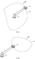
- the laser emitting device is able to track the laser receiving device, the following describes how to measure the pair of the angle and the distance and how to use the obtained angle and distance data to plot a trajectory map of the laser receiving device in conjunction with FIG. 5 and FIG. 6 .
- the method records the angle (e.g., 02) and measures the distance 12 between the laser emitting device 520 and the laser receiving device 560 after the laser emitting device 520 realigns with the laser receiving device 560.
- the laser receiving device 560 rotates around the laser emitting device 520 for at least one round.
- the one round of the rotation is not necessarily in a shape shown in FIG. 5 and may be in other shapes.
- the above-described scheme artificially determines at which point the relative angle and the distance are measured.
- the N counts may be pre-configured.
- a value is pre-configured at the time the timing circuit starts to operate.
- the value corresponds to one of many cooperation modes between the laser emitting device and the laser receiving device.
- the value is pre-configured to be 80, that is, the timing circuit counts to 80 after the laser beam emitted from the laser emitting device rotates for one round.
Landscapes
- Physics & Mathematics (AREA)
- Engineering & Computer Science (AREA)
- General Physics & Mathematics (AREA)
- Radar, Positioning & Navigation (AREA)
- Remote Sensing (AREA)
- Electromagnetism (AREA)
- Computer Networks & Wireless Communication (AREA)
- Optical Radar Systems And Details Thereof (AREA)
Applications Claiming Priority (2)
| Application Number | Priority Date | Filing Date | Title |
|---|---|---|---|
| CN201710662589.5A CN109387826B (zh) | 2017-08-04 | 2017-08-04 | 测量角度、距离的方法、绘制轨迹图方法及激光测距系统 |
| PCT/CN2018/096946 WO2019024731A1 (zh) | 2017-08-04 | 2018-07-25 | 测量角度、距离的方法、绘制轨迹图方法及激光测距系统 |
Publications (3)
| Publication Number | Publication Date |
|---|---|
| EP3663715A1 true EP3663715A1 (de) | 2020-06-10 |
| EP3663715A4 EP3663715A4 (de) | 2021-08-04 |
| EP3663715B1 EP3663715B1 (de) | 2024-10-30 |
Family
ID=65233525
Family Applications (1)
| Application Number | Title | Priority Date | Filing Date |
|---|---|---|---|
| EP18840199.6A Active EP3663715B1 (de) | 2017-08-04 | 2018-07-25 | Winkel- und abstandsmessverfahren, verfahren zum zeichnen von trajektoriediagrammen und laserentfernungsmessungssystem |
Country Status (4)
| Country | Link |
|---|---|
| US (1) | US11150087B2 (de) |
| EP (1) | EP3663715B1 (de) |
| CN (1) | CN109387826B (de) |
| WO (1) | WO2019024731A1 (de) |
Families Citing this family (18)
| Publication number | Priority date | Publication date | Assignee | Title |
|---|---|---|---|---|
| CN107218920B (zh) * | 2017-08-04 | 2020-07-10 | 美国西北仪器公司 | 距离测定方法及距离测定系统 |
| CN109916309B (zh) * | 2019-03-04 | 2024-04-26 | 中铁第四勘察设计院集团有限公司 | 一种基于激光测距的地表裂缝监测装置及方法 |
| CN109974630B (zh) * | 2019-04-26 | 2025-02-07 | 湖北刊江建设工程有限公司 | 角度检测装置 |
| US11577859B1 (en) * | 2019-10-08 | 2023-02-14 | Rockwell Collins, Inc. | Fault resilient airborne network |
| EP4139705A1 (de) * | 2020-04-24 | 2023-03-01 | Crown Equipment Corporation | Kalibrierung einer abstands- und abstandsmessvorrichtung |
| CN114061920B (zh) * | 2020-08-07 | 2025-01-28 | 北京小米移动软件有限公司 | 折叠轨迹检测装置及折叠轨迹检测方法、折叠检测系统 |
| CN112179324B (zh) * | 2020-10-08 | 2022-08-23 | 山西省交通建设工程质量检测中心(有限公司) | 一种桥梁墩柱竖直度检测装置 |
| CN112129264B (zh) * | 2020-10-20 | 2025-02-07 | 四川大学 | 一种激光测距传感器测量系统及测量方法 |
| CN112496863B (zh) * | 2020-11-23 | 2022-10-28 | 中国航发沈阳黎明航空发动机有限责任公司 | 一种数控加工角度自动测量方法 |
| CN112953644B (zh) * | 2021-01-25 | 2022-08-02 | 华中科技大学鄂州工业技术研究院 | 水下机器人群无线通信方法、装置、通信设备及存储介质 |
| WO2022216594A1 (en) * | 2021-04-05 | 2022-10-13 | Milwaukee Electric Tool Corporation | Laser level system |
| EP4320406A4 (de) | 2021-04-05 | 2025-04-09 | Milwaukee Electric Tool Corporation | Rotationslaser mit mechanischer maske |
| CN113581702B (zh) * | 2021-07-06 | 2022-10-11 | 浙江世仓智能仓储设备有限公司 | 一种基于四向车行驶距离的定位方法 |
| CN114683234B (zh) * | 2022-05-09 | 2023-07-18 | 中国石油大学(华东) | 一种管道动火连头快速测量画线自动化装置 |
| CN116202425B (zh) * | 2022-06-15 | 2023-09-12 | 武汉鑫岳光电科技有限公司 | 一种激光测距装置 |
| CN116007595A (zh) * | 2022-12-28 | 2023-04-25 | 湖南中联重科应急装备有限公司 | 用于确定偏摆量的方法、存储介质、处理器及高空作业车 |
| CN116499422B (zh) * | 2023-04-27 | 2025-12-26 | 阿维塔科技(重庆)有限公司 | 一种辅助测试装置及测试方法 |
| CN116379971B (zh) * | 2023-05-29 | 2023-08-11 | 华北理工大学 | 金属构件垂直度激光测量装置及测量方法 |
Family Cites Families (19)
| Publication number | Priority date | Publication date | Assignee | Title |
|---|---|---|---|---|
| US5243397A (en) * | 1992-11-25 | 1993-09-07 | Elop-Electrooptics Industries Ltd. | Distance measuring system |
| BE1008234A5 (nl) * | 1994-03-25 | 1996-02-20 | Sotec B V I O | Werkwijze en inrichting voor het in meer dan een dimensie meten met laserlicht. |
| JP4328653B2 (ja) * | 2004-03-23 | 2009-09-09 | 株式会社トプコン | レーザ測定システム |
| JP5124321B2 (ja) * | 2008-03-21 | 2013-01-23 | 株式会社トプコン | 測定システム |
| JP5124319B2 (ja) * | 2008-03-21 | 2013-01-23 | 株式会社トプコン | 測量機、測量システム、測定対象の検出方法、および測定対象の検出プログラム |
| US8724119B2 (en) * | 2010-04-21 | 2014-05-13 | Faro Technologies, Inc. | Method for using a handheld appliance to select, lock onto, and track a retroreflector with a laser tracker |
| US9400170B2 (en) * | 2010-04-21 | 2016-07-26 | Faro Technologies, Inc. | Automatic measurement of dimensional data within an acceptance region by a laser tracker |
| US9686532B2 (en) * | 2011-04-15 | 2017-06-20 | Faro Technologies, Inc. | System and method of acquiring three-dimensional coordinates using multiple coordinate measurement devices |
| EP2620745A1 (de) * | 2012-01-30 | 2013-07-31 | Hexagon Technology Center GmbH | Vermessungssystem mit einem Vermessungsgerät und einem Scanmodul |
| EP2639548A1 (de) * | 2012-03-15 | 2013-09-18 | Leica Geosystems AG | Laserempfänger mit Funktion zur Erkennung der eigenen Bewegungen |
| EP2687866A1 (de) * | 2012-07-19 | 2014-01-22 | Leica Geosystems AG | Lasertracker mit Kalibriereinheit zur Selbstkalibrierung |
| EP2746806B1 (de) * | 2012-12-21 | 2016-10-19 | Leica Geosystems AG | Selbstkalibrierender Lasertracker und Selbstkalibrierungsverfahren |
| CN103235302B (zh) * | 2013-02-28 | 2014-10-15 | 中国地质大学(武汉) | 基于激光扫描和双探测器的距离与速度测量装置及方法 |
| US9188430B2 (en) * | 2013-03-14 | 2015-11-17 | Faro Technologies, Inc. | Compensation of a structured light scanner that is tracked in six degrees-of-freedom |
| EP2781879B1 (de) * | 2013-03-19 | 2015-09-30 | Leica Geosystems AG | Konstruktionslasersystem aus Rotationslaser und Laserreceiver, mit Funktionalität zur automatischen Bestimmung der Laserreceiver-Richtung |
| CN103345269B (zh) * | 2013-06-30 | 2017-08-25 | 湖南农业大学 | 一种激光发射装置及自动追踪方法 |
| EP2894491B1 (de) * | 2013-12-18 | 2020-05-27 | LG Electronics Inc. | Distanzmessvorrichtung und Verfahren dafür |
| CN205317206U (zh) | 2015-12-10 | 2016-06-15 | 新余学院 | 一种多功能测量工程仪器 |
| CN106802412B (zh) * | 2017-01-23 | 2020-08-04 | 南京大学 | 一种基于激光及无线技术的近距离移动定位系统及其方法 |
-
2017
- 2017-08-04 CN CN201710662589.5A patent/CN109387826B/zh active Active
-
2018
- 2018-07-25 WO PCT/CN2018/096946 patent/WO2019024731A1/zh not_active Ceased
- 2018-07-25 US US16/636,536 patent/US11150087B2/en active Active
- 2018-07-25 EP EP18840199.6A patent/EP3663715B1/de active Active
Also Published As
| Publication number | Publication date |
|---|---|
| WO2019024731A1 (zh) | 2019-02-07 |
| EP3663715B1 (de) | 2024-10-30 |
| US11150087B2 (en) | 2021-10-19 |
| US20210156679A1 (en) | 2021-05-27 |
| EP3663715A4 (de) | 2021-08-04 |
| CN109387826B (zh) | 2024-03-19 |
| CN109387826A (zh) | 2019-02-26 |
Similar Documents
| Publication | Publication Date | Title |
|---|---|---|
| EP3663715B1 (de) | Winkel- und abstandsmessverfahren, verfahren zum zeichnen von trajektoriediagrammen und laserentfernungsmessungssystem | |
| US11486704B2 (en) | Intelligent positioning module | |
| US10823558B2 (en) | Surveying instrument | |
| US7196302B2 (en) | Laser measuring method and laser measuring system having fan-shaped tilted laser beams and three known points of photodetection system | |
| CN108291809B (zh) | 用于检验和/或校准旋转激光器的竖直轴线的方法 | |
| CN105865426B (zh) | 一种自动对中与测量的全站仪 | |
| CN101960256B (zh) | 测量仪器的自动校准 | |
| US7081606B2 (en) | Position measuring system | |
| EP2788715B1 (de) | Robotisches nivellierungsinstrument | |
| US11500096B2 (en) | Surveying instrument | |
| JPH09189551A (ja) | レーザー光線水準器、その操作方法および関連装置 | |
| EP3489625A1 (de) | Vermessungsinstrument | |
| KR101791955B1 (ko) | 측량정보의 오차발생 범위를 최소화하는 수준 측지측량 장치 | |
| JPS5912966B2 (ja) | 測角器を自動整準する方法とその装置 | |
| CN205655835U (zh) | 一种自动对中与测量的全站仪 | |
| JP2019219319A (ja) | 鉛直測定システム及び基準点のトレース方法 | |
| US12571631B2 (en) | Surveying instrument | |
| EP0803044A1 (de) | Ferngesteuerte nivelliervorrichtung | |
| CN109387827B (zh) | 用于在激光发射装置中跟踪激光接收装置的跟踪方法 | |
| CN110108265B (zh) | 一种自主获取地理纬度并自动寻北的陀螺测量仪器 | |
| WO1996030720A1 (en) | Method and apparatus for measuring position and posture of tunnel excavator | |
| JP2024043881A (ja) | 測量装置、測量装置の動作方法およびプログラム | |
| CN207600452U (zh) | 一种激光发射装置 | |
| GB2169768A (en) | Alignment technique | |
| JPS63281012A (ja) | 測量装置 |
Legal Events
| Date | Code | Title | Description |
|---|---|---|---|
| STAA | Information on the status of an ep patent application or granted ep patent |
Free format text: STATUS: THE INTERNATIONAL PUBLICATION HAS BEEN MADE |
|
| PUAI | Public reference made under article 153(3) epc to a published international application that has entered the european phase |
Free format text: ORIGINAL CODE: 0009012 |
|
| STAA | Information on the status of an ep patent application or granted ep patent |
Free format text: STATUS: REQUEST FOR EXAMINATION WAS MADE |
|
| 17P | Request for examination filed |
Effective date: 20200304 |
|
| AK | Designated contracting states |
Kind code of ref document: A1 Designated state(s): AL AT BE BG CH CY CZ DE DK EE ES FI FR GB GR HR HU IE IS IT LI LT LU LV MC MK MT NL NO PL PT RO RS SE SI SK SM TR |
|
| AX | Request for extension of the european patent |
Extension state: BA ME |
|
| DAV | Request for validation of the european patent (deleted) | ||
| DAX | Request for extension of the european patent (deleted) | ||
| RIC1 | Information provided on ipc code assigned before grant |
Ipc: G01C 15/00 20060101AFI20210309BHEP Ipc: G01C 15/06 20060101ALI20210309BHEP Ipc: G01C 3/08 20060101ALI20210309BHEP |
|
| A4 | Supplementary search report drawn up and despatched |
Effective date: 20210705 |
|
| RIC1 | Information provided on ipc code assigned before grant |
Ipc: G01C 15/00 20060101AFI20210629BHEP Ipc: G01C 15/06 20060101ALI20210629BHEP Ipc: G01C 3/08 20060101ALI20210629BHEP |
|
| GRAP | Despatch of communication of intention to grant a patent |
Free format text: ORIGINAL CODE: EPIDOSNIGR1 |
|
| STAA | Information on the status of an ep patent application or granted ep patent |
Free format text: STATUS: GRANT OF PATENT IS INTENDED |
|
| INTG | Intention to grant announced |
Effective date: 20240605 |
|
| GRAS | Grant fee paid |
Free format text: ORIGINAL CODE: EPIDOSNIGR3 |
|
| GRAA | (expected) grant |
Free format text: ORIGINAL CODE: 0009210 |
|
| STAA | Information on the status of an ep patent application or granted ep patent |
Free format text: STATUS: THE PATENT HAS BEEN GRANTED |
|
| AK | Designated contracting states |
Kind code of ref document: B1 Designated state(s): AL AT BE BG CH CY CZ DE DK EE ES FI FR GB GR HR HU IE IS IT LI LT LU LV MC MK MT NL NO PL PT RO RS SE SI SK SM TR |
|
| REG | Reference to a national code |
Ref country code: GB Ref legal event code: FG4D |
|
| REG | Reference to a national code |
Ref country code: CH Ref legal event code: EP |
|
| REG | Reference to a national code |
Ref country code: IE Ref legal event code: FG4D |
|
| REG | Reference to a national code |
Ref country code: DE Ref legal event code: R096 Ref document number: 602018076072 Country of ref document: DE |
|
| REG | Reference to a national code |
Ref country code: LT Ref legal event code: MG9D |
|
| REG | Reference to a national code |
Ref country code: NL Ref legal event code: MP Effective date: 20241030 |
|
| PG25 | Lapsed in a contracting state [announced via postgrant information from national office to epo] |
Ref country code: PT Free format text: LAPSE BECAUSE OF FAILURE TO SUBMIT A TRANSLATION OF THE DESCRIPTION OR TO PAY THE FEE WITHIN THE PRESCRIBED TIME-LIMIT Effective date: 20250228 Ref country code: HR Free format text: LAPSE BECAUSE OF FAILURE TO SUBMIT A TRANSLATION OF THE DESCRIPTION OR TO PAY THE FEE WITHIN THE PRESCRIBED TIME-LIMIT Effective date: 20241030 Ref country code: IS Free format text: LAPSE BECAUSE OF FAILURE TO SUBMIT A TRANSLATION OF THE DESCRIPTION OR TO PAY THE FEE WITHIN THE PRESCRIBED TIME-LIMIT Effective date: 20250228 |
|
| PG25 | Lapsed in a contracting state [announced via postgrant information from national office to epo] |
Ref country code: FI Free format text: LAPSE BECAUSE OF FAILURE TO SUBMIT A TRANSLATION OF THE DESCRIPTION OR TO PAY THE FEE WITHIN THE PRESCRIBED TIME-LIMIT Effective date: 20241030 Ref country code: NL Free format text: LAPSE BECAUSE OF FAILURE TO SUBMIT A TRANSLATION OF THE DESCRIPTION OR TO PAY THE FEE WITHIN THE PRESCRIBED TIME-LIMIT Effective date: 20241030 |
|
| REG | Reference to a national code |
Ref country code: AT Ref legal event code: MK05 Ref document number: 1737252 Country of ref document: AT Kind code of ref document: T Effective date: 20241030 |
|
| PG25 | Lapsed in a contracting state [announced via postgrant information from national office to epo] |
Ref country code: BG Free format text: LAPSE BECAUSE OF FAILURE TO SUBMIT A TRANSLATION OF THE DESCRIPTION OR TO PAY THE FEE WITHIN THE PRESCRIBED TIME-LIMIT Effective date: 20241030 |
|
| PG25 | Lapsed in a contracting state [announced via postgrant information from national office to epo] |
Ref country code: ES Free format text: LAPSE BECAUSE OF FAILURE TO SUBMIT A TRANSLATION OF THE DESCRIPTION OR TO PAY THE FEE WITHIN THE PRESCRIBED TIME-LIMIT Effective date: 20241030 |
|
| PG25 | Lapsed in a contracting state [announced via postgrant information from national office to epo] |
Ref country code: NO Free format text: LAPSE BECAUSE OF FAILURE TO SUBMIT A TRANSLATION OF THE DESCRIPTION OR TO PAY THE FEE WITHIN THE PRESCRIBED TIME-LIMIT Effective date: 20250130 |
|
| PG25 | Lapsed in a contracting state [announced via postgrant information from national office to epo] |
Ref country code: LV Free format text: LAPSE BECAUSE OF FAILURE TO SUBMIT A TRANSLATION OF THE DESCRIPTION OR TO PAY THE FEE WITHIN THE PRESCRIBED TIME-LIMIT Effective date: 20241030 Ref country code: AT Free format text: LAPSE BECAUSE OF FAILURE TO SUBMIT A TRANSLATION OF THE DESCRIPTION OR TO PAY THE FEE WITHIN THE PRESCRIBED TIME-LIMIT Effective date: 20241030 Ref country code: GR Free format text: LAPSE BECAUSE OF FAILURE TO SUBMIT A TRANSLATION OF THE DESCRIPTION OR TO PAY THE FEE WITHIN THE PRESCRIBED TIME-LIMIT Effective date: 20250131 |
|
| PG25 | Lapsed in a contracting state [announced via postgrant information from national office to epo] |
Ref country code: PL Free format text: LAPSE BECAUSE OF FAILURE TO SUBMIT A TRANSLATION OF THE DESCRIPTION OR TO PAY THE FEE WITHIN THE PRESCRIBED TIME-LIMIT Effective date: 20241030 |
|
| PG25 | Lapsed in a contracting state [announced via postgrant information from national office to epo] |
Ref country code: RS Free format text: LAPSE BECAUSE OF FAILURE TO SUBMIT A TRANSLATION OF THE DESCRIPTION OR TO PAY THE FEE WITHIN THE PRESCRIBED TIME-LIMIT Effective date: 20250130 |
|
| PG25 | Lapsed in a contracting state [announced via postgrant information from national office to epo] |
Ref country code: SM Free format text: LAPSE BECAUSE OF FAILURE TO SUBMIT A TRANSLATION OF THE DESCRIPTION OR TO PAY THE FEE WITHIN THE PRESCRIBED TIME-LIMIT Effective date: 20241030 |
|
| PG25 | Lapsed in a contracting state [announced via postgrant information from national office to epo] |
Ref country code: DK Free format text: LAPSE BECAUSE OF FAILURE TO SUBMIT A TRANSLATION OF THE DESCRIPTION OR TO PAY THE FEE WITHIN THE PRESCRIBED TIME-LIMIT Effective date: 20241030 |
|
| PG25 | Lapsed in a contracting state [announced via postgrant information from national office to epo] |
Ref country code: EE Free format text: LAPSE BECAUSE OF FAILURE TO SUBMIT A TRANSLATION OF THE DESCRIPTION OR TO PAY THE FEE WITHIN THE PRESCRIBED TIME-LIMIT Effective date: 20241030 |
|
| PG25 | Lapsed in a contracting state [announced via postgrant information from national office to epo] |
Ref country code: RO Free format text: LAPSE BECAUSE OF FAILURE TO SUBMIT A TRANSLATION OF THE DESCRIPTION OR TO PAY THE FEE WITHIN THE PRESCRIBED TIME-LIMIT Effective date: 20241030 |
|
| PG25 | Lapsed in a contracting state [announced via postgrant information from national office to epo] |
Ref country code: SK Free format text: LAPSE BECAUSE OF FAILURE TO SUBMIT A TRANSLATION OF THE DESCRIPTION OR TO PAY THE FEE WITHIN THE PRESCRIBED TIME-LIMIT Effective date: 20241030 |
|
| PG25 | Lapsed in a contracting state [announced via postgrant information from national office to epo] |
Ref country code: CZ Free format text: LAPSE BECAUSE OF FAILURE TO SUBMIT A TRANSLATION OF THE DESCRIPTION OR TO PAY THE FEE WITHIN THE PRESCRIBED TIME-LIMIT Effective date: 20241030 |
|
| PG25 | Lapsed in a contracting state [announced via postgrant information from national office to epo] |
Ref country code: IT Free format text: LAPSE BECAUSE OF FAILURE TO SUBMIT A TRANSLATION OF THE DESCRIPTION OR TO PAY THE FEE WITHIN THE PRESCRIBED TIME-LIMIT Effective date: 20241030 |
|
| REG | Reference to a national code |
Ref country code: DE Ref legal event code: R097 Ref document number: 602018076072 Country of ref document: DE |
|
| PLBE | No opposition filed within time limit |
Free format text: ORIGINAL CODE: 0009261 |
|
| STAA | Information on the status of an ep patent application or granted ep patent |
Free format text: STATUS: NO OPPOSITION FILED WITHIN TIME LIMIT |
|
| PG25 | Lapsed in a contracting state [announced via postgrant information from national office to epo] |
Ref country code: SE Free format text: LAPSE BECAUSE OF FAILURE TO SUBMIT A TRANSLATION OF THE DESCRIPTION OR TO PAY THE FEE WITHIN THE PRESCRIBED TIME-LIMIT Effective date: 20241030 |
|
| 26N | No opposition filed |
Effective date: 20250731 |
|
| PGFP | Annual fee paid to national office [announced via postgrant information from national office to epo] |
Ref country code: DE Payment date: 20250812 Year of fee payment: 8 |
|
| PGFP | Annual fee paid to national office [announced via postgrant information from national office to epo] |
Ref country code: GB Payment date: 20250826 Year of fee payment: 8 |
|
| PGFP | Annual fee paid to national office [announced via postgrant information from national office to epo] |
Ref country code: FR Payment date: 20250731 Year of fee payment: 8 |
|
| REG | Reference to a national code |
Ref country code: CH Ref legal event code: H13 Free format text: ST27 STATUS EVENT CODE: U-0-0-H10-H13 (AS PROVIDED BY THE NATIONAL OFFICE) Effective date: 20260224 |
|
| PG25 | Lapsed in a contracting state [announced via postgrant information from national office to epo] |
Ref country code: LU Free format text: LAPSE BECAUSE OF NON-PAYMENT OF DUE FEES Effective date: 20250725 |
|
| REG | Reference to a national code |
Ref country code: BE Ref legal event code: MM Effective date: 20250731 |
|
| PG25 | Lapsed in a contracting state [announced via postgrant information from national office to epo] |
Ref country code: BE Free format text: LAPSE BECAUSE OF NON-PAYMENT OF DUE FEES Effective date: 20250731 |
|
| PG25 | Lapsed in a contracting state [announced via postgrant information from national office to epo] |
Ref country code: CH Free format text: LAPSE BECAUSE OF NON-PAYMENT OF DUE FEES Effective date: 20250731 |