EP3663724B1 - Absoluter drehgeber und vorrichtung - Google Patents
Absoluter drehgeber und vorrichtung Download PDFInfo
- Publication number
- EP3663724B1 EP3663724B1 EP19210840.5A EP19210840A EP3663724B1 EP 3663724 B1 EP3663724 B1 EP 3663724B1 EP 19210840 A EP19210840 A EP 19210840A EP 3663724 B1 EP3663724 B1 EP 3663724B1
- Authority
- EP
- European Patent Office
- Prior art keywords
- signal
- absolute position
- sensor
- periodic
- absolute
- Prior art date
- Legal status (The legal status is an assumption and is not a legal conclusion. Google has not performed a legal analysis and makes no representation as to the accuracy of the status listed.)
- Active
Links
Images







Classifications
-
- G—PHYSICS
- G01—MEASURING; TESTING
- G01D—MEASURING NOT SPECIALLY ADAPTED FOR A SPECIFIC VARIABLE; ARRANGEMENTS FOR MEASURING TWO OR MORE VARIABLES NOT COVERED IN A SINGLE OTHER SUBCLASS; TARIFF METERING APPARATUS; MEASURING OR TESTING NOT OTHERWISE PROVIDED FOR
- G01D5/00—Mechanical means for transferring the output of a sensing member; Means for converting the output of a sensing member to another variable where the form or nature of the sensing member does not constrain the means for converting; Transducers not specially adapted for a specific variable
- G01D5/26—Mechanical means for transferring the output of a sensing member; Means for converting the output of a sensing member to another variable where the form or nature of the sensing member does not constrain the means for converting; Transducers not specially adapted for a specific variable characterised by optical transfer means, i.e. using infrared, visible, or ultraviolet light
- G01D5/32—Mechanical means for transferring the output of a sensing member; Means for converting the output of a sensing member to another variable where the form or nature of the sensing member does not constrain the means for converting; Transducers not specially adapted for a specific variable characterised by optical transfer means, i.e. using infrared, visible, or ultraviolet light with attenuation or whole or partial obturation of beams of light
- G01D5/34—Mechanical means for transferring the output of a sensing member; Means for converting the output of a sensing member to another variable where the form or nature of the sensing member does not constrain the means for converting; Transducers not specially adapted for a specific variable characterised by optical transfer means, i.e. using infrared, visible, or ultraviolet light with attenuation or whole or partial obturation of beams of light the beams of light being detected by photocells
- G01D5/347—Mechanical means for transferring the output of a sensing member; Means for converting the output of a sensing member to another variable where the form or nature of the sensing member does not constrain the means for converting; Transducers not specially adapted for a specific variable characterised by optical transfer means, i.e. using infrared, visible, or ultraviolet light with attenuation or whole or partial obturation of beams of light the beams of light being detected by photocells using displacement encoding scales
- G01D5/34776—Absolute encoders with analogue or digital scales
- G01D5/34792—Absolute encoders with analogue or digital scales with only digital scales or both digital and incremental scales
-
- G—PHYSICS
- G01—MEASURING; TESTING
- G01B—MEASURING LENGTH, THICKNESS OR SIMILAR LINEAR DIMENSIONS; MEASURING ANGLES; MEASURING AREAS; MEASURING IRREGULARITIES OF SURFACES OR CONTOURS
- G01B21/00—Measuring arrangements or details thereof, where the measuring technique is not covered by the other groups of this subclass, unspecified or not relevant
- G01B21/02—Measuring arrangements or details thereof, where the measuring technique is not covered by the other groups of this subclass, unspecified or not relevant for measuring length, width, or thickness
- G01B21/04—Measuring arrangements or details thereof, where the measuring technique is not covered by the other groups of this subclass, unspecified or not relevant for measuring length, width, or thickness by measuring coordinates of points
- G01B21/045—Correction of measurements
-
- G—PHYSICS
- G01—MEASURING; TESTING
- G01B—MEASURING LENGTH, THICKNESS OR SIMILAR LINEAR DIMENSIONS; MEASURING ANGLES; MEASURING AREAS; MEASURING IRREGULARITIES OF SURFACES OR CONTOURS
- G01B21/00—Measuring arrangements or details thereof, where the measuring technique is not covered by the other groups of this subclass, unspecified or not relevant
- G01B21/20—Measuring arrangements or details thereof, where the measuring technique is not covered by the other groups of this subclass, unspecified or not relevant for measuring contours or curvatures, e.g. determining profile
-
- G—PHYSICS
- G01—MEASURING; TESTING
- G01D—MEASURING NOT SPECIALLY ADAPTED FOR A SPECIFIC VARIABLE; ARRANGEMENTS FOR MEASURING TWO OR MORE VARIABLES NOT COVERED IN A SINGLE OTHER SUBCLASS; TARIFF METERING APPARATUS; MEASURING OR TESTING NOT OTHERWISE PROVIDED FOR
- G01D5/00—Mechanical means for transferring the output of a sensing member; Means for converting the output of a sensing member to another variable where the form or nature of the sensing member does not constrain the means for converting; Transducers not specially adapted for a specific variable
- G01D5/12—Mechanical means for transferring the output of a sensing member; Means for converting the output of a sensing member to another variable where the form or nature of the sensing member does not constrain the means for converting; Transducers not specially adapted for a specific variable using electric or magnetic means
- G01D5/14—Mechanical means for transferring the output of a sensing member; Means for converting the output of a sensing member to another variable where the form or nature of the sensing member does not constrain the means for converting; Transducers not specially adapted for a specific variable using electric or magnetic means influencing the magnitude of a current or voltage
- G01D5/20—Mechanical means for transferring the output of a sensing member; Means for converting the output of a sensing member to another variable where the form or nature of the sensing member does not constrain the means for converting; Transducers not specially adapted for a specific variable using electric or magnetic means influencing the magnitude of a current or voltage by varying inductance, e.g. by a movable armature
- G01D5/204—Mechanical means for transferring the output of a sensing member; Means for converting the output of a sensing member to another variable where the form or nature of the sensing member does not constrain the means for converting; Transducers not specially adapted for a specific variable using electric or magnetic means influencing the magnitude of a current or voltage by varying inductance, e.g. by a movable armature by influencing the mutual induction between two or more coils
- G01D5/2053—Mechanical means for transferring the output of a sensing member; Means for converting the output of a sensing member to another variable where the form or nature of the sensing member does not constrain the means for converting; Transducers not specially adapted for a specific variable using electric or magnetic means influencing the magnitude of a current or voltage by varying inductance, e.g. by a movable armature by influencing the mutual induction between two or more coils by a movable non-ferromagnetic conductive element
-
- G—PHYSICS
- G01—MEASURING; TESTING
- G01D—MEASURING NOT SPECIALLY ADAPTED FOR A SPECIFIC VARIABLE; ARRANGEMENTS FOR MEASURING TWO OR MORE VARIABLES NOT COVERED IN A SINGLE OTHER SUBCLASS; TARIFF METERING APPARATUS; MEASURING OR TESTING NOT OTHERWISE PROVIDED FOR
- G01D5/00—Mechanical means for transferring the output of a sensing member; Means for converting the output of a sensing member to another variable where the form or nature of the sensing member does not constrain the means for converting; Transducers not specially adapted for a specific variable
- G01D5/12—Mechanical means for transferring the output of a sensing member; Means for converting the output of a sensing member to another variable where the form or nature of the sensing member does not constrain the means for converting; Transducers not specially adapted for a specific variable using electric or magnetic means
- G01D5/14—Mechanical means for transferring the output of a sensing member; Means for converting the output of a sensing member to another variable where the form or nature of the sensing member does not constrain the means for converting; Transducers not specially adapted for a specific variable using electric or magnetic means influencing the magnitude of a current or voltage
- G01D5/20—Mechanical means for transferring the output of a sensing member; Means for converting the output of a sensing member to another variable where the form or nature of the sensing member does not constrain the means for converting; Transducers not specially adapted for a specific variable using electric or magnetic means influencing the magnitude of a current or voltage by varying inductance, e.g. by a movable armature
- G01D5/204—Mechanical means for transferring the output of a sensing member; Means for converting the output of a sensing member to another variable where the form or nature of the sensing member does not constrain the means for converting; Transducers not specially adapted for a specific variable using electric or magnetic means influencing the magnitude of a current or voltage by varying inductance, e.g. by a movable armature by influencing the mutual induction between two or more coils
- G01D5/2086—Mechanical means for transferring the output of a sensing member; Means for converting the output of a sensing member to another variable where the form or nature of the sensing member does not constrain the means for converting; Transducers not specially adapted for a specific variable using electric or magnetic means influencing the magnitude of a current or voltage by varying inductance, e.g. by a movable armature by influencing the mutual induction between two or more coils by movement of two or more coils with respect to two or more other coils
-
- G—PHYSICS
- G01—MEASURING; TESTING
- G01D—MEASURING NOT SPECIALLY ADAPTED FOR A SPECIFIC VARIABLE; ARRANGEMENTS FOR MEASURING TWO OR MORE VARIABLES NOT COVERED IN A SINGLE OTHER SUBCLASS; TARIFF METERING APPARATUS; MEASURING OR TESTING NOT OTHERWISE PROVIDED FOR
- G01D5/00—Mechanical means for transferring the output of a sensing member; Means for converting the output of a sensing member to another variable where the form or nature of the sensing member does not constrain the means for converting; Transducers not specially adapted for a specific variable
- G01D5/12—Mechanical means for transferring the output of a sensing member; Means for converting the output of a sensing member to another variable where the form or nature of the sensing member does not constrain the means for converting; Transducers not specially adapted for a specific variable using electric or magnetic means
- G01D5/244—Mechanical means for transferring the output of a sensing member; Means for converting the output of a sensing member to another variable where the form or nature of the sensing member does not constrain the means for converting; Transducers not specially adapted for a specific variable using electric or magnetic means influencing characteristics of pulses or pulse trains; generating pulses or pulse trains
- G01D5/24471—Error correction
-
- G—PHYSICS
- G01—MEASURING; TESTING
- G01D—MEASURING NOT SPECIALLY ADAPTED FOR A SPECIFIC VARIABLE; ARRANGEMENTS FOR MEASURING TWO OR MORE VARIABLES NOT COVERED IN A SINGLE OTHER SUBCLASS; TARIFF METERING APPARATUS; MEASURING OR TESTING NOT OTHERWISE PROVIDED FOR
- G01D5/00—Mechanical means for transferring the output of a sensing member; Means for converting the output of a sensing member to another variable where the form or nature of the sensing member does not constrain the means for converting; Transducers not specially adapted for a specific variable
- G01D5/12—Mechanical means for transferring the output of a sensing member; Means for converting the output of a sensing member to another variable where the form or nature of the sensing member does not constrain the means for converting; Transducers not specially adapted for a specific variable using electric or magnetic means
- G01D5/244—Mechanical means for transferring the output of a sensing member; Means for converting the output of a sensing member to another variable where the form or nature of the sensing member does not constrain the means for converting; Transducers not specially adapted for a specific variable using electric or magnetic means influencing characteristics of pulses or pulse trains; generating pulses or pulse trains
- G01D5/24471—Error correction
- G01D5/24476—Signal processing
-
- G—PHYSICS
- G01—MEASURING; TESTING
- G01D—MEASURING NOT SPECIALLY ADAPTED FOR A SPECIFIC VARIABLE; ARRANGEMENTS FOR MEASURING TWO OR MORE VARIABLES NOT COVERED IN A SINGLE OTHER SUBCLASS; TARIFF METERING APPARATUS; MEASURING OR TESTING NOT OTHERWISE PROVIDED FOR
- G01D5/00—Mechanical means for transferring the output of a sensing member; Means for converting the output of a sensing member to another variable where the form or nature of the sensing member does not constrain the means for converting; Transducers not specially adapted for a specific variable
- G01D5/12—Mechanical means for transferring the output of a sensing member; Means for converting the output of a sensing member to another variable where the form or nature of the sensing member does not constrain the means for converting; Transducers not specially adapted for a specific variable using electric or magnetic means
- G01D5/244—Mechanical means for transferring the output of a sensing member; Means for converting the output of a sensing member to another variable where the form or nature of the sensing member does not constrain the means for converting; Transducers not specially adapted for a specific variable using electric or magnetic means influencing characteristics of pulses or pulse trains; generating pulses or pulse trains
- G01D5/245—Mechanical means for transferring the output of a sensing member; Means for converting the output of a sensing member to another variable where the form or nature of the sensing member does not constrain the means for converting; Transducers not specially adapted for a specific variable using electric or magnetic means influencing characteristics of pulses or pulse trains; generating pulses or pulse trains using a variable number of pulses in a train
- G01D5/2451—Incremental encoders
- G01D5/2452—Incremental encoders incorporating two or more tracks having an (n, n+1, ...) relationship
-
- G—PHYSICS
- G01—MEASURING; TESTING
- G01D—MEASURING NOT SPECIALLY ADAPTED FOR A SPECIFIC VARIABLE; ARRANGEMENTS FOR MEASURING TWO OR MORE VARIABLES NOT COVERED IN A SINGLE OTHER SUBCLASS; TARIFF METERING APPARATUS; MEASURING OR TESTING NOT OTHERWISE PROVIDED FOR
- G01D5/00—Mechanical means for transferring the output of a sensing member; Means for converting the output of a sensing member to another variable where the form or nature of the sensing member does not constrain the means for converting; Transducers not specially adapted for a specific variable
- G01D5/26—Mechanical means for transferring the output of a sensing member; Means for converting the output of a sensing member to another variable where the form or nature of the sensing member does not constrain the means for converting; Transducers not specially adapted for a specific variable characterised by optical transfer means, i.e. using infrared, visible, or ultraviolet light
- G01D5/32—Mechanical means for transferring the output of a sensing member; Means for converting the output of a sensing member to another variable where the form or nature of the sensing member does not constrain the means for converting; Transducers not specially adapted for a specific variable characterised by optical transfer means, i.e. using infrared, visible, or ultraviolet light with attenuation or whole or partial obturation of beams of light
- G01D5/34—Mechanical means for transferring the output of a sensing member; Means for converting the output of a sensing member to another variable where the form or nature of the sensing member does not constrain the means for converting; Transducers not specially adapted for a specific variable characterised by optical transfer means, i.e. using infrared, visible, or ultraviolet light with attenuation or whole or partial obturation of beams of light the beams of light being detected by photocells
- G01D5/36—Forming the light into pulses
-
- G—PHYSICS
- G06—COMPUTING OR CALCULATING; COUNTING
- G06F—ELECTRIC DIGITAL DATA PROCESSING
- G06F17/00—Digital computing or data processing equipment or methods, specially adapted for specific functions
- G06F17/10—Complex mathematical operations
- G06F17/17—Function evaluation by approximation methods, e.g. inter- or extrapolation, smoothing, least mean square method
Definitions
- the present invention relates to an absolute rotary encoder.
- an absolute rotary encoder which generates two sets of two-phase signals from two periodic patterns having different periods, and detects an absolute position of a scale or a sensor from a difference (phase difference) between a phase of one set of two-phase signals and a phase of the other set of two-phase signals is known.
- the absolute rotary encoder in order to detect the absolute position with high accuracy, it is necessary to take measures against decentering when the scale is decentered with respect to a rotational shaft of the scale.
- Japanese Laid-Open Patent Publication No. 2018-059714 discloses an absolute rotary encoder that extracts a decentering component by taking a difference between an absolute angle signal with the decentering component canceled and an absolute angle signal having the decentering component.
- EP 3 301 401 A1 discloses an eccentricity calculating method for determining eccentricity information of a rotary encoder of a robot apparatus, involving acquiring an output signal from a sensor unit, where phase information is determined based on the output signal.
- the present invention provides an absolute rotary encoder capable of expanding the allowable mounting range.
- the present invention in its first aspect provides an absolute rotary encoder as specified in claims 1 to 9.
- the present invention in its second aspect provide an apparatus as specified in claim 10.
- An absolute rotary encoder described in each embodiment is used in various apparatuses such as an optical apparatus, and can detect an absolute position of a movable member in accordance with a relative movement between a scale and a sensor according to a movement of the movable member in the apparatus.
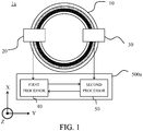
- FIG. 1 is a diagram illustrating a configuration of an encoder 1a according to this embodiment.
- the encoder 1a includes a scale 10, a sensor (first sensor) 20, a sensor (second sensor) 30, and a processor 500a.
- the processor 500a includes a first processor 40 and a second processor 50.
- the encoder 1a is a reflective optical absolute rotary encoder that detects the absolute position of the movable member. In this embodiment, a case will be described in which the encoder 1a detects a rotation position (rotation angle) of a rotational shaft (not shown) of the movable member as the absolute position.
- the reflective optical absolute rotary encoder will be described as an example of the encoder 1a, but the present invention is not limited to this.
- the present invention is also applicable to encoders having different detection methods, such as a transmissive optical absolute rotary encoder, a magnetic absolute rotary encoder, and an electromagnetic induction magnetic absolute rotary encoder.
- the scale 10 is attached so as to rotate integrally with the rotational shaft of the movable member.
- the sensors 20 and 30 are attached to a fixed member.
- the sensors 20 and 30 are movable relative to the scale 10 and are attached to face each other in a radial direction of the scale 10.
- the scale 10 may be attached to the fixed member, and the sensors 20 and 30 may be attached to the rotational shaft of the movable member so as to face each other.
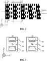
- FIG. 2 is an enlarged view of a part of the scale 10 and shows a plurality of (two in this embodiment) tracks 11 and 12 provided on the scale 10 with different diameters.
- Each track is provided with a periodic pattern including reflective portions (black portions in the drawing) and non-reflecting portions (white portions in the drawing) that are alternately arranged at a constant period (pitch).
- a plurality of (two in this embodiment) periodic patterns having different pitches are alternately provided in each track along a direction orthogonal to a detection direction (hereinafter referred to as a scale width direction).
- the track 11 is provided with a periodic pattern with a pitch P1 and a periodic pattern with a pitch P2 alternately along the scale width direction.
- the number of gratings of the periodic pattern with the pitches P1 and P2 is 1649 and 388, respectively.
- the track 12 is provided with a periodic pattern with a pitch Q1 and a periodic pattern with a pitch Q2 alternately along the scale width direction.
- the number of gratings of the periodic patterns with the pitches Q1 and Q2 is 1632 and 384, respectively.
- the number of gratings of the periodic pattern with the pitch P1 and the number of gratings of the periodic patterns with the pitch Q1 are substantially equal, and the number of gratings of the periodic pattern with the pitch P2 and the number of gratings of the periodic patterns with the pitch Q2 are substantially equal.
- FIG. 3 is a diagram illustrating a configuration of the sensors 20 and 30.
- the sensor 20 includes a light source 200 and a plurality (two in this embodiment) of light-receiving portions (detectors) 201 and 202.
- the light source 200 and the light-receiving portions 201 and 202 are arranged on the same plane.
- the light source 200 is configured by a light-emitting element such as an LED.
- the light-receiving portion 201 is configured by a plurality of photoelectric conversion elements (light-receiving elements) that photoelectrically convert light emitted from the light source 200 and reflected by a reflective portion of the track 11.
- the light-receiving portion 202 is configured by a plurality of photoelectric conversion elements (light-receiving elements) that photoelectrically convert light emitted from the light source 200 and reflected by a reflective portion of the track 12.
- photoelectric conversion elements light-receiving elements
- an intensity of the reflected light received by the light-receiving elements in the light-receiving portions 201 and 202 changes according to the relative displacement amount.
- the sensor 20 outputs a sine wave signal corresponding to the change in the light-receiving intensity in the light-receiving portion 201 and outputs a sine wave signal corresponding to the change in the light-receiving intensity in the light-receiving portion 202.
- a sensor 30 is described by replacing the light source 200 described above with a light source 300 and the light-receiving portions 201 and 202 with light-receiving portions 301 and 302.
- the switching of the detection cycle is performed by changing the light-receiving elements that outputs signals A(+), B(+), A(-), and B(-).
- FIG. 4A shows a configuration of the light-receiving portion when the light-receiving portion 201 reads the periodic pattern with the pitch P1 or the light-receiving portion 202 reads the periodic pattern with the pitch Q1.
- the detection cycle is the pitch P1 or the pitch Q1
- outputs of the light-receiving elements 20a, 20b, 20c, and 20d are treated as signals A(+), B(+), A(-), and B(-), respectively.
- FIG. 4B shows a configuration of the light-receiving portion when the light-receiving portion 201 reads the periodic pattern with the pitch P2 or the light-receiving portion 202 reads the periodic pattern with the pitch Q2.
- the detection cycle is the pitch P2 or the pitch Q2
- sixteen light-receiving elements arranged along a position detection direction are set as a set for every four adjacent ones, and outputs of each set are treated as signals A(+), B(+), A(-), B(-).
- FIG. 4C shows a reading area on the scale 10 of the sensor 20.
- the detection cycle is set to the pitch P1
- the light-receiving portion 201 reads the periodic pattern 11a with the pitch P1.
- two-phase pseudo sine wave signals (two-phase signals of PI) having a phase difference of about 90 degrees from each other corresponding to the pitch P1 are output.
- the detection cycle is set to the pitch P2
- the light-receiving portion 201 reads the periodic pattern 11b with the pitch P2.
- two-phase pseudo sine wave signals two-phase signals of P2 having a phase difference of about 90 degrees from each other corresponding to the pitch P2 are output.
- the light-receiving portion 202 reads the periodic pattern 12a with the pitch Q1. In this case, two-phase pseudo sine wave signals (two-phase signals of Q1) having a phase difference of about 90 degrees from each other corresponding to the pitch Q1 are output.
- the detection cycle is set to the pitch Q2
- the light-receiving portion 202 reads the periodic pattern 12b with the pitch Q2. In this case, two-phase pseudo sine wave signals (two-phase signals of Q2) having a phase difference of about 90 degrees from each other corresponding to the pitch Q2 are output.
- a reading area 113 on the track by the light-receiving portion 201 and a reading area 123 on the track by the light-receiving portion 202 are ranges in which the light emitted from the light source is reflected so as to be received by each light-receiving portion.
- Each reading area is set so as to include a plurality of combinations of two periodic patterns arranged alternately along the scale width direction in the track.
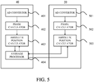
- FIG. 5 is a diagram illustrating configurations of a first processor 40 and a second processor 50.
- the first processor 40 includes an AD converter 401, a phase calculator 402, an absolute position calculator 403, and an average processor 404.
- the second processor 50 includes an AD converter 501, a phase calculator 502, and an absolute position calculator 503.
- a process performed in the first processor 40 is referred to as a first process
- a process performed in the second processor 50 is referred to as a second process.
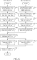
- FIG. 6 is a flowchart showing the first process and the second process.
- the processes in steps S401 to S40_8 correspond to the first process, and the processes in steps S50_1 to S50_6 correspond to the second process. Firstly, the first process will be described.
- step S40_1 the AD converter 401 converts each two sets of two-phase signals (the two-phase signals of P1 and P2 and the two-phase signals of Q1 and Q2) output from the light-receiving portions 201 and 202 into digital signals.
- step S40_2 the phase calculator 402 calculates a phase from each two sets of two-phase signals converted into the digital signals by the AD converter 401. Since the two-phase signals are signals (sine wave signal and cosine wave signal) having a phase difference of about 90 degrees from each other as described above, the phase calculator 402 calculates the phase by arctan calculation.
- the phase calculated from the two-phase signals of P1 is ⁇ P1
- the phase calculated from the two-phase signals of P2 is ⁇ P2
- the phase calculated from the two-phase signals of Q1 is ⁇ Q1
- the phase calculated from the two-phase signals of Q2 is ⁇ Q2.
- the numbers of gratings of the periodic patterns with the pitches P1, P2, Q1, and Q2 are 1649, 388, 1632, and 384, respectively. Therefore, the phases ⁇ P1, ⁇ P2, ⁇ Q1, and ⁇ Q2 are a signal of 1649 periods, a signal of 388 periods, a signal 1632 periods, and a signal of 384 periods, respectively.
- phase is calculated by the arctan calculation.
- any parameter other than the phase may be calculated as long as it represents a position within a specific range.
- step S40_3 the absolute position calculator 403 first uses the following equations (1) to (3) to calculate a signal of 97 periods ( ⁇ P97), a signal of 388 periods ( ⁇ P388), and a signal of 1649 periods ( ⁇ P1649).
- MOD(x, y) represents a remainder when x is a dividend and y is a divisor.
- the accuracy of ⁇ P1649 is the highest and the accuracy of ⁇ P97 is the lowest. Therefore, in this embodiment, the signal of 97 periods having the accuracy of ⁇ P1649 is calculated. Specifically, as shown in FIGs. 7A to 7D , ⁇ P388 changes 388 times from 0 to 2 ⁇ over the entire track circumference, while ⁇ P97 changes 97 times from 0 to 2 ⁇ over the entire track circumference. That is, a change amount of the phase of ⁇ P97 is 1/4 of ⁇ P388.
- the absolute position calculator 403 calculates the period number m20_4 of ⁇ P388 and a signal x388_97 of 97 periods having an accuracy of ⁇ P388 by using the following equations (4) and (5).
- ROUND (x) represents an integer value obtained by rounding off the first decimal place of x.
- the absolute position calculator 403 uses the following equations (6) and (7) to calculate a period number m20_17 of ⁇ P1649 and a signal x1649_97 of 97 periods (first periodic signal) having an accuracy of ⁇ P1649.
- step S40_4 the absolute position calculator 403 first uses the following equations (8) to (10) to calculate a signal of 96 periods ( ⁇ Q96), a signal of 384 periods ( ⁇ Q384), and a signal of 1632 periods ( ⁇ Q1632).
- the absolute position calculator 403 uses the following equations (11) and (12) to calculate a period number n20_4 of ⁇ Q384 and a signal x384_96 of 96 periods having an accuracy of ⁇ Q384.
- the absolute position calculator 403 uses the following equations (13) and (14) to calculate a period number n20_17 of ⁇ Q1632 and a signal x1632_96 of 96 periods (second periodic signal) having an accuracy of ⁇ Q1632.
- step S40_5 an absolute position signal (first position signal) x20 in the sensor 20 that is one period around the entire track circumference is calculated by using the following equation (15).
- x 20 MOD x 1649 _ 97 ⁇ x 1632 _ 96,2 ⁇
- step S50_1 the AD converter 501 converts each two sets of two-phase signals (the two-phase signals of P1 and P2 and the two-phase signals of Q1 and Q2) output from the light-receiving portions 301 and 302 into digital signals.
- step S50_2 the phase calculator 502 calculates a phase from each two sets of two-phase signals converted into the digital signals by the AD converter 501. Since the two-phase signals are signals having a phase difference of about 90 degrees from each other, the phase calculator 502 calculates the phase by the arctan calculation.
- the phase calculated from the two-phase signals of P1 is ⁇ R1
- the phase calculated from the two-phase signals of P2 is ⁇ R2
- the phase calculated from the two-phase signals of Q1 is ⁇ S1
- the phase calculated from the two-phase signals of Q2 is ⁇ S2.
- the phases ⁇ R1, ⁇ R2, ⁇ S1, and ⁇ S2 are a signal of 1649 periods, a signal of 388 periods, a signal of 1632 periods, and a signal of 384 periods, respectively.
- step S50_3 the absolute position calculator 503 first uses the following equations (16) to (18) to calculate a signal of 97 periods ( ⁇ R97), a signal of 388 periods ( ⁇ R388), and a signal of 1649 periods ( ⁇ R1649).
- the absolute position calculator 503 calculates a period number m30_4 of ⁇ R388 and a signal y388_97 of 97 periods having an accuracy of ⁇ R388 by using the following equations (19) and (20).
- the absolute position calculator 503 uses the following equations (21) and (22) to calculate a period number m30_17 of ⁇ R1649 and a signal y1649_97 of 97 periods (third periodic signal) having an accuracy of ⁇ R1649.
- step S50_4 the absolute position calculator 503 first uses the following equations (23) to (25) to calculate a signal of 96 periods ( ⁇ S96), a signal of 384 periods ( ⁇ S384), and a signal of 1632 periods ( ⁇ S1632).
- the absolute position calculator 503 calculates a period number n30_4 of ⁇ S384 and a signal y384_96 of 96 periods having an accuracy of ⁇ S384 by using the following equations (26) and (27).
- the absolute position calculator 503 calculates a period number n30_17 of ⁇ S1632 and a signal y1632_96 of 96 periods (fourth periodic signal) having an accuracy of ⁇ S1632 by using the following equations (28) and (29).
- step S50_5 an absolute position signal (second position signal) x30 in the sensor 30 that is one period around the entire track circumference is calculated by using the following equation (30).
- x 30 MOD y 1649 _ 97 ⁇ y 1632 _ 96,2 ⁇
- step S40_6 the average processor 404 calculates an absolute position signal (third position signal) x1 by averaging the absolute position signals x20 and x30 by using the following equation (31). By performing this process, it is possible to improve decentering fluctuation tolerance.
- the process for improving the decentering fluctuation tolerance is referred to as decentering correction.
- a rounding error d will be described as an index for ensuring reliability of the absolute position.
- the rounding error is a difference between values before and after rounding in rounding processing when obtaining the period number.
- the period number m20_4 of ⁇ P388 is acquired using ROUND(x). That is, since the rounded value by rounding off is the period number m20_4, the rounding error in the expression (4) can be acquired by subtracting the period number m20_4 from the value before rounding off (non-rounded value).
- the rounding error is expressed within a range of ⁇ 0.5, and if it is close to +0.5 or -0.5, it can be said that the rounding process is not performed correctly. That is, there is a high possibility that the period number is shifted and the absolute position cannot be acquired correctly.
- FIGs. 8A-8C are graphs showing the rounding error in a state where the absolute position is correctly acquired.
- FIGs. 9A to 9C are graphs showing the rounding error in a state where there is a high possibility that the absolute position is not correctly acquired.
- FIGs. 8A-8C and FIGs. 9A-9C show the period number before rounding off, the period number after rounding off, and a difference (rounding error) between the period numbers before and after rounding off, respectively.
- the absolute position signal x20 is added with a decentering error ⁇ 0 expressed by the following equation (33).
- RopM and RopS represent an optical center in the track 11 and an optical center in the track 12, respectively.
- ⁇ 0 ⁇ RopM ⁇ ⁇ RopS ⁇ sin ⁇
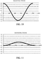
- FIG. 10 is a diagram illustrating the rounding error when the absolute position signal is acquired without performing the decentering correction. As described above, when the absolute position signal is acquired without performing the decentering correction, the decentering error is added and the rounding error becomes large.
- a decentering error ⁇ 0 is added to the absolute position signal x1.
- the absolute position signal x1 is an average of the absolute position signals read from the sensors 20 and 30 arranged so as to face each other (i.e. the one subjected to the decentering correction)
- the decentering error ⁇ 0 is expressed by the following equation (35).
- ⁇ 0 ⁇ RopM ⁇ ⁇ RopS ⁇ sin ⁇ + ⁇ RopM ⁇ ⁇ RopS ⁇ sin ⁇ + 180 ° 2
- FIG. 11 is a diagram illustrating the rounding error when the absolute position signal is acquired by performing the decentering correction.
- FIG. 12 is a diagram showing a relationship between the opposing arrangement angle of the sensors 20 and 30 and the rounding error.
- the arrangement angle in the diagram means an angle formed by the sensors 20 and 30 with respect to a radial center of the scale 10 on a plane including a radial direction of the scale 10.
- the opposing arrangement angle is set within a range where the rounding error does not exceed a threshold.
- the threshold of the rounding error is set to 0.4.
- the graph curve in FIG. 12 is merely an example.
- step S40_7 the absolute position calculator 403 combines the absolute position signal x1 and the signal x1649_97 by using the following equations (36) and (37). As a result, a period number m20_97 of the signal x1649_97 and an absolute position signal (fourth position signal) x1649_1 having an accuracy of the signal x1649_97 are calculated.
- step S50_6 the absolute position calculator 503 combines the absolute position signal x1 and the signal y1649_97 by using the following equations (38) and (39). As a result, a period number m30_97 of the signal y1649_97 and an absolute position signal (fifth position signal) y1649_1 having an accuracy of the signal y1649_97 are calculated.
- step S40_8 the average processor 404 calculates an absolute position signal z1 by averaging the absolute position signals x1649_1 and y1649_1 using the following equation (40).
- z 1 ⁇ MOD x 1649 _ 1 + y 1649 _ 1 2 , 2 ⁇ .... when x 1649 _ 1 ⁇ y 1649 _ 1 ⁇ ⁇ MOD x 1649 _ 1 + y 1649 _ 1 + 2 ⁇ 2 , 2 ⁇ .... when x 1649 _ 1 ⁇ y 1649 _ 1 ⁇ ⁇ ⁇ ⁇
- the absolute position signal z1 can be accurately calculated even when the scale 10 is decentered with respect to the rotational shaft. Thereby, it becomes possible to expand the attachment allowable range.
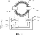
- FIG. 13 is a diagram illustrating a configuration of an encoder 1b according to this embodiment.
- the encoder 1b includes a scale 110, a sensor 120, a sensor 130, and a processor 500b.
- the processor 500b includes a first processor 140, a second processor 150, and a third processor 160.
- the encoder 1b is a reflective optical absolute rotary encoder that detects an absolute position of a movable member. In this embodiment, a case will be described in which the encoder 1b detects a rotation angle of a rotational shaft (not shown) of the movable member as the absolute position.
- the reflective optical absolute rotary encoder will be described as an example of the encoder 1b, but the present invention is not limited to this.
- the present invention can also be applied to encoders having different detection methods, for example, a transmissive optical absolute rotary encoder, a magnetic absolute rotary encoder, and an electromagnetic induction magnetic absolute rotary encoder.
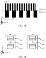
- FIG. 14 is an enlarged view of a part of the scale 110, and shows a plurality (two in this embodiment) of tracks 111 and 112 provided on the scale 110 with different diameters.
- each track is provided with the plurality of periodic patterns having different pitches along the scale width direction.
- each track is provided with a periodic pattern having a predetermined pitch.
- the track 111 is provided with a periodic pattern having a pitch T1.
- the number of gratings of the periodic pattern with the pitch T1 is 97.
- the track 112 is provided with a periodic pattern having a pitch U1.
- the number of gratings of the periodic pattern with the pitch U1 is 24.
- FIG. 15 is a diagram illustrating a configuration of the sensors 120 and 130.
- the sensor 120 includes a light source 1200 and a plurality (two in this embodiment) of light-receiving portions (detectors) 1201 and 1202.
- the light source 1200 and the light-receiving portions 1201 and 1202 are arranged on the same plane.
- the light source 1200 is configured by a light-emitting element such as an LED.
- the light-receiving portion 1201 is configured by a plurality of photoelectric conversion elements (light-receiving elements) that photoelectrically convert light emitted from the light source 1200 and reflected by a reflection portion of the track 111.
- the light-receiving portion 1202 is configured by a plurality of photoelectric conversion elements (light-receiving elements) that photoelectrically convert light emitted from the light source 1200 and reflected by a reflection portion of the track 112.
- photoelectric conversion elements light-receiving elements
- an intensity of the reflected light received by the light-receiving elements in the light-receiving portions 1201 and 1202 changes according to the relative displacement amount.
- the sensor 120 outputs a sine wave signal corresponding to the change in the light-receiving intensity in the light-receiving portion 1201 and outputs a sine wave signal corresponding to the change in the light-receiving intensity in the light-receiving portion 1202.
- the sensor 130 is described by replacing the light source 1200 described above with a light source 1300 and the light-receiving portions 1201 and 1202 with light-receiving portions 1301 and 1302.
- An arrangement of the light-receiving elements of the light-receiving portion 1201 is the same as the arrangement of the light-receiving elements in FIG. 4A described in the first embodiment.
- a detection cycle of the light-receiving portion 1201 is always constant, and is set to a detection cycle T1 that coincides with or sufficiently close to the pitch T1.
- An arrangement of the light-receiving elements of the light-receiving portion 1202 is the same as the arrangement of the light-receiving elements in FIG. 4B described in the first embodiment.
- a detection cycle of the light-receiving portion 1202 is always constant, and is set to a detection cycle 4*T1 that coincides with or sufficiently close to the pitch U1.
- the sensor 130 is described by replacing the light source 1200 described above with 1300 and the light-receiving portions 1201 and 1202 with 1301 and 1302.
- FIG. 16 shows a reading area on the scale in the sensor 120.
- the light-receiving portion 1201 reads a pattern 1111 having the pitch T1.
- two-phase pseudo sine wave signals having a phase difference of about 90 degrees from each other corresponding to the pitch T1 i.e. two-phase signals of T1
- the light-receiving portion 1202 reads a pattern 1121 having the pitch U1.
- two-phase pseudo sine wave signals having a phase difference of about 90 degrees from each other corresponding to the pitch U1 i.e. two-phase signals of U1 are output.
- a reading area 1112 on the track by the light-receiving portion 1201 and a reading area 1122 on the track by the light-receiving portion 1202 are ranges in which light emitted from the light source is reflected so as to be received by each light-receiving portion.
- the sensor 120 has been described above, the sensor 130 is described by replacing the light-receiving portions 1201 and 1202 described above with 1301 and 1302.
- FIG. 17 is a diagram illustrating a configuration of the first processor 140, the second processor 150, and the third processor 160.
- the first processor 140 includes an AD converter 1401, a phase calculator 1402, and an absolute position calculator 1403.
- the second processor 150 includes an AD converter 1501, a phase calculator 1502, and an absolute position calculator 1503.
- the third processor 160 includes an average processor 1601.
- a process performed by the first processor 140 is referred to as a first process
- a process performed by the second processor 150 is referred to as a second process
- a process performed by the third processor 160 is referred to as a third process.
- the AD converter 1401 converts two sets of two-phase signals (two-phase signals of T1 and two-phase signals of Ul) output from the light-receiving portions 1201 and 1202 into digital signals.
- the phase calculator 1402 calculates a phase from each two sets of two-phase signals converted into the digital signals by the AD converter 1401. Since the two-phase signals are signals having a phase difference of about 90 degrees from each other as described above, the phase calculator 1402 calculates the phase by arctan calculation.
- the phase (first periodic signal) calculated from the two-phase signals of T1 is ⁇ T97
- the phase (second periodic signal) calculated from the two-phase signals of U1 is ⁇ U24.
- the number of gratings in the periodic pattern with pitches T1 and U1 is 97 and 24, respectively. Therefore, the phases ⁇ T97 and ⁇ U24 are a signal of 97 periods and a signal of 24 periods, respectively.
- phase is calculated by the arctan calculation.
- any parameter other than the phase may be calculated as long as it represents a position within a specific range.
- the AD converter 1501 converts two sets of two-phase signals (two-phase signals of T1 and two-phase signals of U1) output from the light-receiving portions 1301 and 1302 into digital signals.
- the phase calculator 1502 calculates a phase from each two sets of two-phase signals converted into the digital signals by the AD converter 1501. Since the two-phase signals are signals having a phase difference of about 90 degrees from each other as described above, the phase calculator 1502 calculates the phase by the arctan calculation.
- the phase (third periodic signal) calculated from the two-phase signals of T1 is ⁇ V97
- the phase (fourth periodic signal) calculated from the two-phase signals of U1 is ⁇ W24.
- the number of gratings in the periodic pattern with pitches T1 and U1 is 97 and 24, respectively. Therefore, the phases ⁇ V97 and ⁇ W24 are a signal of 97 periods and a signal of 24 periods, respectively.
- the average processor 1601 first acquirers an absolute position signal (third position signal) x1 from the signals x120 and x130 using the following equation (43). By performing this process, it is possible to improve the decentering fluctuation tolerance. Since the improvement of the decentering fluctuation tolerance has been described in the first embodiment, the description thereof is omitted in this embodiment.
- x 1 ⁇ MOD x 120 + x 130 2 , 2 ⁇ ⁇ when x 120 ⁇ x 130 MOD x 120 + x 130 + 2 ⁇ 2 , 2 ⁇ ⁇ when x 120 ⁇ x 130
- the absolute position calculator 1403 and 1503 process the absolute position signal x1, and calculate an absolute position signal with higher accuracy. Specifically, the absolute position calculator 1403 combines the absolute position signal x1 and the phase ⁇ T97 by using the following equations (44) and (45). As a result, a period number m120_97 of the phase ⁇ T97 and an absolute position signal (fourth position signal) x97_1 having an accuracy of the phase ⁇ T97 are calculated.
- the absolute position calculator 1503 combines the absolute position signal x1 and the phase ⁇ V97 by using the following equations (46) and (47). As a result, a period number n120_97 of the phase ⁇ V97 and an absolute position signal (fifth position signal) y97_1 having an accuracy of the phase ⁇ V97 are calculated.
- the average processor 1601 acquirers an absolute position signal z1 by averaging the absolute position signals x97_1 and y97_1 by using the following equation (48).
- z 1 ⁇ MOD x 97 _ 1 + y 97 _ 1 2 , 2 ⁇ .... when x 97 _ 1 ⁇ y 97 _ 1 ⁇ ⁇ MOD x 97 _ 1 + y 97 _ 1 + 2 ⁇ 2 , 2 ⁇ .... when x 97 _ 1 ⁇ y 97 _ 1 ⁇ ⁇ ⁇
- the absolute position signal z1 can be accurately calculated even when the scale 110 is decentered with respect to the rotational shaft. Thereby, it becomes possible to expand the attachment allowable range.
- FIG. 18 is a diagram illustrating a configuration of an encoder 1c according to this embodiment.
- the encoder 1c includes a scale 210, a sensor 220, a sensor 230, and a processor 500c. Since a configuration and attachment of the scale 210 and the sensors 220 and 230 are the same as those in the first embodiment or the second embodiment, the description thereof is omitted. In this embodiment, parts different from the first and second embodiments will be described.
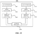
- FIG. 19 is a diagram illustrating a configuration of the processor 500c.
- the processor 500c includes AD converters 2401 and 2411, phase calculators 2402 and 2412, absolute position calculators 2403 and 2413, and an average processor 2404.
- the processor 500c executes all of the first process, the second process, and the third process described in the second embodiment. A method for acquiring an absolute position signal is the same as that in the second embodiment, and thus the description thereof is omitted.
- FIG. 20 is a diagram illustrating a robot arm 2000 equipped with the encoder 1a described in the first embodiment.
- the encoder 1a is attached to each shaft and used to detect an absolute rotation position of each shaft.
- the scale 10 is attached to a movable member that rotates in each shaft.
- the movable member is rotated by an actuator (not shown).
- the encoder 1a detects the absolute rotation position of each shaft of the robot arm 2000 and outputs position information to a CPU (not shown).
- the CPU drives the actuator based on the position information and moves the robot arm 2000 to a target position.
- the encoder of the present invention is not limited to the robot arm 2000 but can be used in various applications of various apparatuses such as position detection of a print head and paper feed roller of a printer (optical apparatus), and rotation position detection of a photosensitive drum of a copying machine (optical apparatus) and the like.
- An encoder comprises first and second sensors which reads first and second tracks, the first and second sensors being arranged in a radial direction to face each other, and a processor which generates a first position signal based on first and second periodic signals based on a signal obtained by reading the first and second tracks by the first sensor, and generates a second position signal based on third and fourth periodic signals based on a signal obtained by reading the first and second tracks by the second sensor, wherein the processor generates an absolute position signal indicating an absolute position of at least one of the scale, the first sensor, or the second sensor based on the first and second position signals and the first and third periodic signals.
Landscapes
- Physics & Mathematics (AREA)
- General Physics & Mathematics (AREA)
- Engineering & Computer Science (AREA)
- Data Mining & Analysis (AREA)
- Theoretical Computer Science (AREA)
- Pure & Applied Mathematics (AREA)
- Mathematical Analysis (AREA)
- Mathematical Optimization (AREA)
- Computational Mathematics (AREA)
- Mathematical Physics (AREA)
- Algebra (AREA)
- Software Systems (AREA)
- General Engineering & Computer Science (AREA)
- Databases & Information Systems (AREA)
- Signal Processing (AREA)
- Transmission And Conversion Of Sensor Element Output (AREA)
- Optical Transform (AREA)
- Manipulator (AREA)
Claims (10)
- Absoluter Drehgeber (1a, 1b, 1c) mit:einer Skala (10, 110, 210), auf der eine erste Spur und eine zweite Spur mit voneinander verschiedenen Durchmessern bereitgestellt sind;einem ersten Sensor (20, 120, 220), der dazu eingerichtet ist, sich relativ zu der Skala zu bewegen und die erste Spur und die zweite Spur zu lesen;einem zweiten Sensor (30, 130, 230), der derart angeordnet ist, dass er dem ersten Sensor in einer radialen Richtung der Skala gegenüberliegt, und der dazu eingerichtet ist, sich relativ zu der Skala zu bewegen und die erste Spur und die zweite Spur zu lesen; undeinem Prozessor (500a, 500b, 500c), der dazu eingerichtet ist, ein erstes absolutes Positionssignal zu erzeugen, indem er eine Differenz zwischen einem ersten periodischen Signal basierend auf einem Signal, das durch Lesen der ersten Spur durch den ersten Sensor erhalten wird, und einem zweiten periodischen Signal basierend auf einem Signal, das durch Lesen der zweiten Spur durch den ersten Sensor erhalten wird, bildet, und ein zweites absolutes Positionssignal zu erzeugen, indem er eine Differenz zwischen einem dritten periodischen Signal basierend auf einem Signal, das durch Lesen der ersten Spur durch den zweiten Sensor erhalten wird, und einem vierten periodischen Signal basierend auf einem Signal, das durch Lesen der zweiten Spur durch den zweiten Sensor erhalten wird, bildet,dadurch gekennzeichnet, dass der Prozessor dazu eingerichtet ist, das erste absolute Positionssignal und das zweite absolute Positionssignal zu mitteln, um ein drittes absolutes Positionssignal zu erzeugen, das dritte absolute Positionssignal und das erste periodische Signal zu kombinieren, um ein viertes absolutes Positionssignal zu erzeugen, das dritte absolute Positionssignal und das dritte periodische Signal zu kombinieren, um ein fünftes absolutes Positionssignal zu erzeugen, und das vierte absolute Positionssignal und das fünfte absolute Positionssignal zu mitteln, um ein absolutes Positionssignal zu erzeugen, das mindestens eine absolute Position der Skala, des ersten Sensors oder des zweiten Sensors angibt.
- Absoluter Drehgeber nach Anspruch 1,
dadurch gekennzeichnet, dass der Prozessor das Nachstehende beinhaltet:einen ersten Prozessor, der dazu eingerichtet ist, das erste absolute Positionssignal und das absolute Positionssignal zu erzeugen undeinen zweiten Prozessor, der dazu eingerichtet ist, das zweite absolute Positionssignal zu erzeugen. - Absoluter Drehgeber nach Anspruch 1,
dadurch gekennzeichnet, dass der Prozessor das Nachstehende beinhaltet:einen ersten Prozessor, der dazu eingerichtet ist, das erste absolute Positionssignal zu erzeugen,einen zweiten Prozessor, der dazu eingerichtet ist, das zweite absolute Positionssignal zu erzeugen,
undeinen dritten Prozessor, der dazu eingerichtet ist, das absolute Positionssignal zu erzeugen. - Absoluter Drehgeber nach einem der Ansprüche 1 bis 3,dadurch gekennzeichnet, dass der Prozessor dazu eingerichtet ist, das erste absolute Positionssignal zu erzeugen, indem er eine Differenz zwischen dem ersten periodischen Signal, multipliziert mit einer ganzen Zahl, und dem zweiten periodischen Signal, multipliziert mit einer ganzen Zahl, bildet, unddas zweite absolute Positionssignal zu erzeugen, indem er eine Differenz zwischen dem dritten periodischen Signal, multipliziert mit einer ganzen Zahl, und dem vierten periodischen Signal, multipliziert mit einer ganzen Zahl, bildet.
- Absoluter Drehgeber nach einem der Ansprüche 1 bis 4, dadurch gekennzeichnet, dassdie erste Spur ein erstes periodisches Muster und ein zweites periodisches Muster beinhaltet, mit voneinander verschiedenen Perioden,die zweite Spur ein drittes periodisches Muster mit einer Periode, die von denen des ersten und des zweiten periodischen Musters verschieden ist, und ein viertes periodisches Muster mit einer Periode, die von denen des ersten bis dritten periodischen Musters verschieden ist, beinhaltet, undder Prozessor dazu eingerichtet ist,das erste periodische Signal zu erzeugen, indem er ein Signal entsprechend jeweils dem ersten und dem zweiten periodischen Muster verarbeitet, unddas zweite periodische Signal zu erzeugen, indem er ein Signal entsprechend jeweils dem dritten und dem vierten periodischen Muster verarbeitet.
- Absoluter Drehgeber nach einem der Ansprüche 1 bis 5, dadurch gekennzeichnet, dass der erste Sensor und der zweite Sensor jeweils Erfassungseinrichtungen mit unterschiedlichen Erfassungszyklen beinhalten.
- Absoluter Drehgeber nach einem der Ansprüche 1 bis 6, dadurch gekennzeichnet, dass der erste Sensor und der zweite Sensor jeweils Erfassungseinrichtungen beinhalten, die einen Erfassungszyklus schalten können.
- Absoluter Drehgeber nach einem der Ansprüche 1 bis 7, dadurch gekennzeichnet, dass ein gegenüberliegender Anordnungswinkel zwischen dem ersten Sensor und dem zweiten Sensor in einem Bereich eingestellt wird, in dem ein Rundungsfehler, der eine Zuverlässigkeit der absoluten Position angibt, eine Schwelle nicht überschreitet.
- Absoluter Drehgeber nach Anspruch 8, dadurch gekennzeichnet, dass die Schwelle 0,4 beträgt.
- Vorrichtung mit:einem beweglichen Element, das dazu eingerichtet ist, sich zu drehen; undeinem absoluten Drehgeber nach einem der Ansprüche 1 bis 9, der dazu eingerichtet ist, eine Drehposition des beweglichen Elements zu erfassen.
Applications Claiming Priority (1)
| Application Number | Priority Date | Filing Date | Title |
|---|---|---|---|
| JP2018226384A JP7203584B2 (ja) | 2018-12-03 | 2018-12-03 | アブソリュートロータリエンコーダ |
Publications (2)
| Publication Number | Publication Date |
|---|---|
| EP3663724A1 EP3663724A1 (de) | 2020-06-10 |
| EP3663724B1 true EP3663724B1 (de) | 2021-04-28 |
Family
ID=68654343
Family Applications (1)
| Application Number | Title | Priority Date | Filing Date |
|---|---|---|---|
| EP19210840.5A Active EP3663724B1 (de) | 2018-12-03 | 2019-11-22 | Absoluter drehgeber und vorrichtung |
Country Status (3)
| Country | Link |
|---|---|
| US (1) | US11079223B2 (de) |
| EP (1) | EP3663724B1 (de) |
| JP (1) | JP7203584B2 (de) |
Families Citing this family (2)
| Publication number | Priority date | Publication date | Assignee | Title |
|---|---|---|---|---|
| JP7173010B2 (ja) * | 2017-07-27 | 2022-11-16 | 株式会社ニコン | 校正装置、エンコーダ装置、駆動装置、ステージ装置、ロボット装置、エンコーダ装置の製造方法、及び校正プログラム |
| US12366470B2 (en) * | 2021-06-28 | 2025-07-22 | Asahi Kasei Microdevices Corporation | Calibration apparatus, calibration method, and non-transitory computer readable medium having recorded thereon calibration program |
Family Cites Families (10)
| Publication number | Priority date | Publication date | Assignee | Title |
|---|---|---|---|---|
| JP2002250639A (ja) * | 2001-02-23 | 2002-09-06 | Sankyo Seiki Mfg Co Ltd | 絶対位置検出エンコーダ |
| DE102005033402A1 (de) * | 2005-07-18 | 2007-01-25 | Robert Bosch Gmbh | Verfahren zur Auswertung von Phasensignalen mit vervielfachter Fehlertoleranz |
| JP5538870B2 (ja) * | 2009-12-24 | 2014-07-02 | キヤノン株式会社 | ロータリーエンコーダ |
| JP5787513B2 (ja) * | 2010-12-15 | 2015-09-30 | キヤノン株式会社 | アブソリュートロータリーエンコーダ |
| JP6245941B2 (ja) * | 2012-12-10 | 2017-12-13 | Dmg森精機株式会社 | 変位検出装置 |
| JP6147038B2 (ja) * | 2013-03-15 | 2017-06-14 | キヤノン株式会社 | 位置検出装置、レンズ装置、撮像システム、および、工作装置 |
| JP6207208B2 (ja) * | 2013-04-12 | 2017-10-04 | キヤノン株式会社 | 位置検出手段 |
| JP6533360B2 (ja) * | 2013-10-30 | 2019-06-19 | キヤノン株式会社 | 位置検出装置及びそれを有するレンズ装置及び撮影装置 |
| JP2016014612A (ja) * | 2014-07-03 | 2016-01-28 | キヤノン株式会社 | エンコーダ |
| JP2018059714A (ja) * | 2016-09-30 | 2018-04-12 | キヤノン株式会社 | 偏芯算出方法、ロータリエンコーダ、ロボットアーム及びロボット装置 |
-
2018
- 2018-12-03 JP JP2018226384A patent/JP7203584B2/ja active Active
-
2019
- 2019-11-22 EP EP19210840.5A patent/EP3663724B1/de active Active
- 2019-11-25 US US16/695,002 patent/US11079223B2/en not_active Expired - Fee Related
Also Published As
| Publication number | Publication date |
|---|---|
| US11079223B2 (en) | 2021-08-03 |
| US20200173774A1 (en) | 2020-06-04 |
| JP2020091104A (ja) | 2020-06-11 |
| JP7203584B2 (ja) | 2023-01-13 |
| EP3663724A1 (de) | 2020-06-10 |
Similar Documents
| Publication | Publication Date | Title |
|---|---|---|
| US8476578B2 (en) | Rotary encoder and rotation mechanism including the same | |
| EP2778623B1 (de) | Positionsmess-, Linsenvorrichtung, Bildaufnahmesystem und Maschinenwerkzeugapparat | |
| EP2564165B1 (de) | Absolutkodierer | |
| JP5574899B2 (ja) | ロータリーエンコーダ及びこれを備えた光学機器 | |
| EP2894437B1 (de) | Codierer, Vorrichtung mit Codierer, Codiererberechnungsverfahren, Codiererberechnungsprogramm und Speichermedium zur Speicherung des Codiererberechnungsprogramms | |
| EP3301401B1 (de) | Exzentrizitätsberechnungsverfahren, drehgeber, robotischer arm und robotervorrichtung | |
| EP2466267B1 (de) | Absolutdrehcodierer | |
| EP2343510B1 (de) | Drehcodierer | |
| JP5932285B2 (ja) | エンコーダおよびこれを備えた装置 | |
| JP5968062B2 (ja) | 位置検出エンコーダおよびこれを用いた装置 | |
| WO2005050137A2 (en) | Absolute encoder employing concatenated, multi-bit, interpolated sub-encoders | |
| EP3663724B1 (de) | Absoluter drehgeber und vorrichtung | |
| EP2937672A1 (de) | Absolutcodierer, verarbeitungsverfahren, programm, ansteuerungsvorrichtung und industriemaschine | |
| US7321113B2 (en) | Precision material-handling robot employing high-resolution, compact absolute encoder | |
| US9000356B2 (en) | Encoder | |
| EP2778626B1 (de) | Positionsdetektionsvorrichtung, Linsenvorrichtung, Bildaufnahmesystem, Werkzeugmaschinenvorrichtung, Positionsdetektionsverfahren, Programm und Speichermedium | |
| US9423276B2 (en) | Measurement apparatus, measurement method, and absolute encoder | |
| JP4900140B2 (ja) | 光学式エンコーダ | |
| JP2023019809A (ja) | アブソリュートロータリエンコーダ及びそれを備える装置 | |
| JP2015094682A (ja) | エンコーダ、エンコーダを備えた装置、位置検出方法および位置検出処理プログラム |
Legal Events
| Date | Code | Title | Description |
|---|---|---|---|
| PUAI | Public reference made under article 153(3) epc to a published international application that has entered the european phase |
Free format text: ORIGINAL CODE: 0009012 |
|
| STAA | Information on the status of an ep patent application or granted ep patent |
Free format text: STATUS: THE APPLICATION HAS BEEN PUBLISHED |
|
| AK | Designated contracting states |
Kind code of ref document: A1 Designated state(s): AL AT BE BG CH CY CZ DE DK EE ES FI FR GB GR HR HU IE IS IT LI LT LU LV MC MK MT NL NO PL PT RO RS SE SI SK SM TR |
|
| AX | Request for extension of the european patent |
Extension state: BA ME |
|
| STAA | Information on the status of an ep patent application or granted ep patent |
Free format text: STATUS: REQUEST FOR EXAMINATION WAS MADE |
|
| 17P | Request for examination filed |
Effective date: 20200811 |
|
| GRAP | Despatch of communication of intention to grant a patent |
Free format text: ORIGINAL CODE: EPIDOSNIGR1 |
|
| STAA | Information on the status of an ep patent application or granted ep patent |
Free format text: STATUS: GRANT OF PATENT IS INTENDED |
|
| INTG | Intention to grant announced |
Effective date: 20201217 |
|
| RIN1 | Information on inventor provided before grant (corrected) |
Inventor name: KUDO, KOUSUKE Inventor name: SASAKI, RYO |
|
| GRAS | Grant fee paid |
Free format text: ORIGINAL CODE: EPIDOSNIGR3 |
|
| GRAA | (expected) grant |
Free format text: ORIGINAL CODE: 0009210 |
|
| STAA | Information on the status of an ep patent application or granted ep patent |
Free format text: STATUS: THE PATENT HAS BEEN GRANTED |
|
| AK | Designated contracting states |
Kind code of ref document: B1 Designated state(s): AL AT BE BG CH CY CZ DE DK EE ES FI FR GB GR HR HU IE IS IT LI LT LU LV MC MK MT NL NO PL PT RO RS SE SI SK SM TR |
|
| REG | Reference to a national code |
Ref country code: GB Ref legal event code: FG4D |
|
| REG | Reference to a national code |
Ref country code: CH Ref legal event code: EP |
|
| REG | Reference to a national code |
Ref country code: AT Ref legal event code: REF Ref document number: 1387559 Country of ref document: AT Kind code of ref document: T Effective date: 20210515 |
|
| REG | Reference to a national code |
Ref country code: DE Ref legal event code: R096 Ref document number: 602019004277 Country of ref document: DE |
|
| REG | Reference to a national code |
Ref country code: IE Ref legal event code: FG4D |
|
| REG | Reference to a national code |
Ref country code: LT Ref legal event code: MG9D |
|
| REG | Reference to a national code |
Ref country code: AT Ref legal event code: MK05 Ref document number: 1387559 Country of ref document: AT Kind code of ref document: T Effective date: 20210428 |
|
| PG25 | Lapsed in a contracting state [announced via postgrant information from national office to epo] |
Ref country code: NL Free format text: LAPSE BECAUSE OF FAILURE TO SUBMIT A TRANSLATION OF THE DESCRIPTION OR TO PAY THE FEE WITHIN THE PRESCRIBED TIME-LIMIT Effective date: 20210428 Ref country code: BG Free format text: LAPSE BECAUSE OF FAILURE TO SUBMIT A TRANSLATION OF THE DESCRIPTION OR TO PAY THE FEE WITHIN THE PRESCRIBED TIME-LIMIT Effective date: 20210728 Ref country code: AT Free format text: LAPSE BECAUSE OF FAILURE TO SUBMIT A TRANSLATION OF THE DESCRIPTION OR TO PAY THE FEE WITHIN THE PRESCRIBED TIME-LIMIT Effective date: 20210428 Ref country code: LT Free format text: LAPSE BECAUSE OF FAILURE TO SUBMIT A TRANSLATION OF THE DESCRIPTION OR TO PAY THE FEE WITHIN THE PRESCRIBED TIME-LIMIT Effective date: 20210428 Ref country code: HR Free format text: LAPSE BECAUSE OF FAILURE TO SUBMIT A TRANSLATION OF THE DESCRIPTION OR TO PAY THE FEE WITHIN THE PRESCRIBED TIME-LIMIT Effective date: 20210428 Ref country code: FI Free format text: LAPSE BECAUSE OF FAILURE TO SUBMIT A TRANSLATION OF THE DESCRIPTION OR TO PAY THE FEE WITHIN THE PRESCRIBED TIME-LIMIT Effective date: 20210428 |
|
| PG25 | Lapsed in a contracting state [announced via postgrant information from national office to epo] |
Ref country code: IS Free format text: LAPSE BECAUSE OF FAILURE TO SUBMIT A TRANSLATION OF THE DESCRIPTION OR TO PAY THE FEE WITHIN THE PRESCRIBED TIME-LIMIT Effective date: 20210828 Ref country code: GR Free format text: LAPSE BECAUSE OF FAILURE TO SUBMIT A TRANSLATION OF THE DESCRIPTION OR TO PAY THE FEE WITHIN THE PRESCRIBED TIME-LIMIT Effective date: 20210729 Ref country code: NO Free format text: LAPSE BECAUSE OF FAILURE TO SUBMIT A TRANSLATION OF THE DESCRIPTION OR TO PAY THE FEE WITHIN THE PRESCRIBED TIME-LIMIT Effective date: 20210728 Ref country code: LV Free format text: LAPSE BECAUSE OF FAILURE TO SUBMIT A TRANSLATION OF THE DESCRIPTION OR TO PAY THE FEE WITHIN THE PRESCRIBED TIME-LIMIT Effective date: 20210428 Ref country code: PL Free format text: LAPSE BECAUSE OF FAILURE TO SUBMIT A TRANSLATION OF THE DESCRIPTION OR TO PAY THE FEE WITHIN THE PRESCRIBED TIME-LIMIT Effective date: 20210428 Ref country code: SE Free format text: LAPSE BECAUSE OF FAILURE TO SUBMIT A TRANSLATION OF THE DESCRIPTION OR TO PAY THE FEE WITHIN THE PRESCRIBED TIME-LIMIT Effective date: 20210428 Ref country code: RS Free format text: LAPSE BECAUSE OF FAILURE TO SUBMIT A TRANSLATION OF THE DESCRIPTION OR TO PAY THE FEE WITHIN THE PRESCRIBED TIME-LIMIT Effective date: 20210428 Ref country code: PT Free format text: LAPSE BECAUSE OF FAILURE TO SUBMIT A TRANSLATION OF THE DESCRIPTION OR TO PAY THE FEE WITHIN THE PRESCRIBED TIME-LIMIT Effective date: 20210830 |
|
| REG | Reference to a national code |
Ref country code: NL Ref legal event code: MP Effective date: 20210428 |
|
| PG25 | Lapsed in a contracting state [announced via postgrant information from national office to epo] |
Ref country code: EE Free format text: LAPSE BECAUSE OF FAILURE TO SUBMIT A TRANSLATION OF THE DESCRIPTION OR TO PAY THE FEE WITHIN THE PRESCRIBED TIME-LIMIT Effective date: 20210428 Ref country code: ES Free format text: LAPSE BECAUSE OF FAILURE TO SUBMIT A TRANSLATION OF THE DESCRIPTION OR TO PAY THE FEE WITHIN THE PRESCRIBED TIME-LIMIT Effective date: 20210428 Ref country code: SK Free format text: LAPSE BECAUSE OF FAILURE TO SUBMIT A TRANSLATION OF THE DESCRIPTION OR TO PAY THE FEE WITHIN THE PRESCRIBED TIME-LIMIT Effective date: 20210428 Ref country code: CZ Free format text: LAPSE BECAUSE OF FAILURE TO SUBMIT A TRANSLATION OF THE DESCRIPTION OR TO PAY THE FEE WITHIN THE PRESCRIBED TIME-LIMIT Effective date: 20210428 Ref country code: DK Free format text: LAPSE BECAUSE OF FAILURE TO SUBMIT A TRANSLATION OF THE DESCRIPTION OR TO PAY THE FEE WITHIN THE PRESCRIBED TIME-LIMIT Effective date: 20210428 Ref country code: RO Free format text: LAPSE BECAUSE OF FAILURE TO SUBMIT A TRANSLATION OF THE DESCRIPTION OR TO PAY THE FEE WITHIN THE PRESCRIBED TIME-LIMIT Effective date: 20210428 Ref country code: SM Free format text: LAPSE BECAUSE OF FAILURE TO SUBMIT A TRANSLATION OF THE DESCRIPTION OR TO PAY THE FEE WITHIN THE PRESCRIBED TIME-LIMIT Effective date: 20210428 |
|
| REG | Reference to a national code |
Ref country code: DE Ref legal event code: R097 Ref document number: 602019004277 Country of ref document: DE |
|
| PLBE | No opposition filed within time limit |
Free format text: ORIGINAL CODE: 0009261 |
|
| STAA | Information on the status of an ep patent application or granted ep patent |
Free format text: STATUS: NO OPPOSITION FILED WITHIN TIME LIMIT |
|
| 26N | No opposition filed |
Effective date: 20220131 |
|
| PG25 | Lapsed in a contracting state [announced via postgrant information from national office to epo] |
Ref country code: IS Free format text: LAPSE BECAUSE OF FAILURE TO SUBMIT A TRANSLATION OF THE DESCRIPTION OR TO PAY THE FEE WITHIN THE PRESCRIBED TIME-LIMIT Effective date: 20210828 Ref country code: AL Free format text: LAPSE BECAUSE OF FAILURE TO SUBMIT A TRANSLATION OF THE DESCRIPTION OR TO PAY THE FEE WITHIN THE PRESCRIBED TIME-LIMIT Effective date: 20210428 |
|
| PG25 | Lapsed in a contracting state [announced via postgrant information from national office to epo] |
Ref country code: MC Free format text: LAPSE BECAUSE OF FAILURE TO SUBMIT A TRANSLATION OF THE DESCRIPTION OR TO PAY THE FEE WITHIN THE PRESCRIBED TIME-LIMIT Effective date: 20210428 |
|
| PG25 | Lapsed in a contracting state [announced via postgrant information from national office to epo] |
Ref country code: LU Free format text: LAPSE BECAUSE OF NON-PAYMENT OF DUE FEES Effective date: 20211122 Ref country code: IT Free format text: LAPSE BECAUSE OF FAILURE TO SUBMIT A TRANSLATION OF THE DESCRIPTION OR TO PAY THE FEE WITHIN THE PRESCRIBED TIME-LIMIT Effective date: 20210428 Ref country code: BE Free format text: LAPSE BECAUSE OF NON-PAYMENT OF DUE FEES Effective date: 20211130 |
|
| REG | Reference to a national code |
Ref country code: BE Ref legal event code: MM Effective date: 20211130 |
|
| PG25 | Lapsed in a contracting state [announced via postgrant information from national office to epo] |
Ref country code: IE Free format text: LAPSE BECAUSE OF NON-PAYMENT OF DUE FEES Effective date: 20211122 |
|
| PG25 | Lapsed in a contracting state [announced via postgrant information from national office to epo] |
Ref country code: FR Free format text: LAPSE BECAUSE OF NON-PAYMENT OF DUE FEES Effective date: 20211130 |
|
| PGFP | Annual fee paid to national office [announced via postgrant information from national office to epo] |
Ref country code: DE Payment date: 20220930 Year of fee payment: 4 |
|
| PG25 | Lapsed in a contracting state [announced via postgrant information from national office to epo] |
Ref country code: CY Free format text: LAPSE BECAUSE OF FAILURE TO SUBMIT A TRANSLATION OF THE DESCRIPTION OR TO PAY THE FEE WITHIN THE PRESCRIBED TIME-LIMIT Effective date: 20210428 |
|
| REG | Reference to a national code |
Ref country code: CH Ref legal event code: PL |
|
| PG25 | Lapsed in a contracting state [announced via postgrant information from national office to epo] |
Ref country code: LI Free format text: LAPSE BECAUSE OF NON-PAYMENT OF DUE FEES Effective date: 20221130 Ref country code: HU Free format text: LAPSE BECAUSE OF FAILURE TO SUBMIT A TRANSLATION OF THE DESCRIPTION OR TO PAY THE FEE WITHIN THE PRESCRIBED TIME-LIMIT; INVALID AB INITIO Effective date: 20191122 Ref country code: CH Free format text: LAPSE BECAUSE OF NON-PAYMENT OF DUE FEES Effective date: 20221130 |
|
| PG25 | Lapsed in a contracting state [announced via postgrant information from national office to epo] |
Ref country code: MK Free format text: LAPSE BECAUSE OF FAILURE TO SUBMIT A TRANSLATION OF THE DESCRIPTION OR TO PAY THE FEE WITHIN THE PRESCRIBED TIME-LIMIT Effective date: 20210428 |
|
| REG | Reference to a national code |
Ref country code: DE Ref legal event code: R119 Ref document number: 602019004277 Country of ref document: DE |
|
| PG25 | Lapsed in a contracting state [announced via postgrant information from national office to epo] |
Ref country code: TR Free format text: LAPSE BECAUSE OF FAILURE TO SUBMIT A TRANSLATION OF THE DESCRIPTION OR TO PAY THE FEE WITHIN THE PRESCRIBED TIME-LIMIT Effective date: 20210428 |
|
| GBPC | Gb: european patent ceased through non-payment of renewal fee |
Effective date: 20231122 |
|
| PG25 | Lapsed in a contracting state [announced via postgrant information from national office to epo] |
Ref country code: MT Free format text: LAPSE BECAUSE OF FAILURE TO SUBMIT A TRANSLATION OF THE DESCRIPTION OR TO PAY THE FEE WITHIN THE PRESCRIBED TIME-LIMIT Effective date: 20210428 |
|
| PG25 | Lapsed in a contracting state [announced via postgrant information from national office to epo] |
Ref country code: DE Free format text: LAPSE BECAUSE OF NON-PAYMENT OF DUE FEES Effective date: 20240601 |
|
| PG25 | Lapsed in a contracting state [announced via postgrant information from national office to epo] |
Ref country code: GB Free format text: LAPSE BECAUSE OF NON-PAYMENT OF DUE FEES Effective date: 20231122 |
|
| PG25 | Lapsed in a contracting state [announced via postgrant information from national office to epo] |
Ref country code: GB Free format text: LAPSE BECAUSE OF NON-PAYMENT OF DUE FEES Effective date: 20231122 Ref country code: DE Free format text: LAPSE BECAUSE OF NON-PAYMENT OF DUE FEES Effective date: 20240601 |