EP3663738A2 - Agencement comprenant un conduit tubulaire ainsi que dispositif de surveillance d'un tel agencement - Google Patents
Agencement comprenant un conduit tubulaire ainsi que dispositif de surveillance d'un tel agencement Download PDFInfo
- Publication number
- EP3663738A2 EP3663738A2 EP19213922.8A EP19213922A EP3663738A2 EP 3663738 A2 EP3663738 A2 EP 3663738A2 EP 19213922 A EP19213922 A EP 19213922A EP 3663738 A2 EP3663738 A2 EP 3663738A2
- Authority
- EP
- European Patent Office
- Prior art keywords
- pipeline
- electrical
- wire
- conductor
- electrical conductor
- Prior art date
- Legal status (The legal status is an assumption and is not a legal conclusion. Google has not performed a legal analysis and makes no representation as to the accuracy of the status listed.)
- Withdrawn
Links
- 238000012544 monitoring process Methods 0.000 title claims abstract description 12
- 239000004020 conductor Substances 0.000 claims abstract description 108
- 239000004033 plastic Substances 0.000 claims abstract description 36
- 229920003023 plastic Polymers 0.000 claims abstract description 36
- 238000010292 electrical insulation Methods 0.000 claims abstract description 19
- 239000000463 material Substances 0.000 claims abstract description 10
- 230000001681 protective effect Effects 0.000 claims description 41
- 238000000034 method Methods 0.000 claims description 14
- RYGMFSIKBFXOCR-UHFFFAOYSA-N Copper Chemical compound [Cu] RYGMFSIKBFXOCR-UHFFFAOYSA-N 0.000 claims description 9
- VNNRSPGTAMTISX-UHFFFAOYSA-N chromium nickel Chemical compound [Cr].[Ni] VNNRSPGTAMTISX-UHFFFAOYSA-N 0.000 claims description 8
- 229910000990 Ni alloy Inorganic materials 0.000 claims description 4
- 239000007769 metal material Substances 0.000 claims description 4
- 239000010410 layer Substances 0.000 abstract description 33
- 239000011241 protective layer Substances 0.000 abstract description 3
- 238000009413 insulation Methods 0.000 description 15
- 238000005259 measurement Methods 0.000 description 11
- 238000001125 extrusion Methods 0.000 description 10
- 238000001514 detection method Methods 0.000 description 9
- 238000004519 manufacturing process Methods 0.000 description 8
- 238000011161 development Methods 0.000 description 7
- 230000018109 developmental process Effects 0.000 description 7
- 230000008901 benefit Effects 0.000 description 5
- 229910052751 metal Inorganic materials 0.000 description 5
- 239000002184 metal Substances 0.000 description 5
- 229910018487 Ni—Cr Inorganic materials 0.000 description 4
- 238000010438 heat treatment Methods 0.000 description 4
- 238000005299 abrasion Methods 0.000 description 3
- 230000004888 barrier function Effects 0.000 description 3
- 229910052802 copper Inorganic materials 0.000 description 3
- 239000010949 copper Substances 0.000 description 3
- 239000007788 liquid Substances 0.000 description 3
- 229910052782 aluminium Inorganic materials 0.000 description 2
- XAGFODPZIPBFFR-UHFFFAOYSA-N aluminium Chemical compound [Al] XAGFODPZIPBFFR-UHFFFAOYSA-N 0.000 description 2
- 239000002131 composite material Substances 0.000 description 2
- 238000010276 construction Methods 0.000 description 2
- 238000009434 installation Methods 0.000 description 2
- 230000035515 penetration Effects 0.000 description 2
- 230000008569 process Effects 0.000 description 2
- 239000002689 soil Substances 0.000 description 2
- 239000000126 substance Substances 0.000 description 2
- XLYOFNOQVPJJNP-UHFFFAOYSA-N water Substances O XLYOFNOQVPJJNP-UHFFFAOYSA-N 0.000 description 2
- 229910000831 Steel Inorganic materials 0.000 description 1
- 229910045601 alloy Inorganic materials 0.000 description 1
- 239000000956 alloy Substances 0.000 description 1
- 238000009412 basement excavation Methods 0.000 description 1
- 230000005540 biological transmission Effects 0.000 description 1
- 230000008859 change Effects 0.000 description 1
- 230000007423 decrease Effects 0.000 description 1
- 230000002950 deficient Effects 0.000 description 1
- 230000001419 dependent effect Effects 0.000 description 1
- 238000011982 device technology Methods 0.000 description 1
- 238000005516 engineering process Methods 0.000 description 1
- 230000007613 environmental effect Effects 0.000 description 1
- 238000011156 evaluation Methods 0.000 description 1
- 239000012530 fluid Substances 0.000 description 1
- 239000011888 foil Substances 0.000 description 1
- 229910052500 inorganic mineral Inorganic materials 0.000 description 1
- 239000002346 layers by function Substances 0.000 description 1
- 150000002739 metals Chemical class 0.000 description 1
- 239000011707 mineral Substances 0.000 description 1
- 238000012806 monitoring device Methods 0.000 description 1
- 229910000623 nickel–chromium alloy Inorganic materials 0.000 description 1
- 239000002245 particle Substances 0.000 description 1
- 230000002093 peripheral effect Effects 0.000 description 1
- 229920000098 polyolefin Polymers 0.000 description 1
- 239000004810 polytetrafluoroethylene Substances 0.000 description 1
- 229920001343 polytetrafluoroethylene Polymers 0.000 description 1
- 239000011253 protective coating Substances 0.000 description 1
- 230000008439 repair process Effects 0.000 description 1
- 230000035945 sensitivity Effects 0.000 description 1
- 239000002356 single layer Substances 0.000 description 1
- 239000010959 steel Substances 0.000 description 1
Images



Classifications
-
- F—MECHANICAL ENGINEERING; LIGHTING; HEATING; WEAPONS; BLASTING
- F17—STORING OR DISTRIBUTING GASES OR LIQUIDS
- F17D—PIPE-LINE SYSTEMS; PIPE-LINES
- F17D5/00—Protection or supervision of installations
- F17D5/02—Preventing, monitoring, or locating loss
- F17D5/06—Preventing, monitoring, or locating loss using electric or acoustic means
-
- F—MECHANICAL ENGINEERING; LIGHTING; HEATING; WEAPONS; BLASTING
- F16—ENGINEERING ELEMENTS AND UNITS; GENERAL MEASURES FOR PRODUCING AND MAINTAINING EFFECTIVE FUNCTIONING OF MACHINES OR INSTALLATIONS; THERMAL INSULATION IN GENERAL
- F16L—PIPES; JOINTS OR FITTINGS FOR PIPES; SUPPORTS FOR PIPES, CABLES OR PROTECTIVE TUBING; MEANS FOR THERMAL INSULATION IN GENERAL
- F16L11/00—Hoses, i.e. flexible pipes
- F16L11/04—Hoses, i.e. flexible pipes made of rubber or flexible plastics
- F16L11/12—Hoses, i.e. flexible pipes made of rubber or flexible plastics with arrangements for particular purposes, e.g. specially profiled, with protecting layer, heated, electrically conducting
- F16L11/127—Hoses, i.e. flexible pipes made of rubber or flexible plastics with arrangements for particular purposes, e.g. specially profiled, with protecting layer, heated, electrically conducting electrically conducting
-
- F—MECHANICAL ENGINEERING; LIGHTING; HEATING; WEAPONS; BLASTING
- F16—ENGINEERING ELEMENTS AND UNITS; GENERAL MEASURES FOR PRODUCING AND MAINTAINING EFFECTIVE FUNCTIONING OF MACHINES OR INSTALLATIONS; THERMAL INSULATION IN GENERAL
- F16L—PIPES; JOINTS OR FITTINGS FOR PIPES; SUPPORTS FOR PIPES, CABLES OR PROTECTIVE TUBING; MEANS FOR THERMAL INSULATION IN GENERAL
- F16L9/00—Rigid pipes
- F16L9/12—Rigid pipes of plastics with or without reinforcement
- F16L9/133—Rigid pipes of plastics with or without reinforcement the walls consisting of two layers
-
- G—PHYSICS
- G01—MEASURING; TESTING
- G01M—TESTING STATIC OR DYNAMIC BALANCE OF MACHINES OR STRUCTURES; TESTING OF STRUCTURES OR APPARATUS, NOT OTHERWISE PROVIDED FOR
- G01M3/00—Investigating fluid-tightness of structures
- G01M3/02—Investigating fluid-tightness of structures by using fluid or vacuum
- G01M3/04—Investigating fluid-tightness of structures by using fluid or vacuum by detecting the presence of fluid at the leakage point
- G01M3/16—Investigating fluid-tightness of structures by using fluid or vacuum by detecting the presence of fluid at the leakage point using electric detection means
- G01M3/18—Investigating fluid-tightness of structures by using fluid or vacuum by detecting the presence of fluid at the leakage point using electric detection means for pipes, cables or tubes; for pipe joints or seals; for valves; for welds; for containers, e.g. radiators
-
- G—PHYSICS
- G01—MEASURING; TESTING
- G01M—TESTING STATIC OR DYNAMIC BALANCE OF MACHINES OR STRUCTURES; TESTING OF STRUCTURES OR APPARATUS, NOT OTHERWISE PROVIDED FOR
- G01M3/00—Investigating fluid-tightness of structures
- G01M3/02—Investigating fluid-tightness of structures by using fluid or vacuum
- G01M3/04—Investigating fluid-tightness of structures by using fluid or vacuum by detecting the presence of fluid at the leakage point
- G01M3/16—Investigating fluid-tightness of structures by using fluid or vacuum by detecting the presence of fluid at the leakage point using electric detection means
- G01M3/18—Investigating fluid-tightness of structures by using fluid or vacuum by detecting the presence of fluid at the leakage point using electric detection means for pipes, cables or tubes; for pipe joints or seals; for valves; for welds; for containers, e.g. radiators
- G01M3/182—Investigating fluid-tightness of structures by using fluid or vacuum by detecting the presence of fluid at the leakage point using electric detection means for pipes, cables or tubes; for pipe joints or seals; for valves; for welds; for containers, e.g. radiators for tubes
-
- G—PHYSICS
- G01—MEASURING; TESTING
- G01M—TESTING STATIC OR DYNAMIC BALANCE OF MACHINES OR STRUCTURES; TESTING OF STRUCTURES OR APPARATUS, NOT OTHERWISE PROVIDED FOR
- G01M3/00—Investigating fluid-tightness of structures
- G01M3/40—Investigating fluid-tightness of structures by using electric means, e.g. by observing electric discharges
Definitions
- the present invention relates to an arrangement comprising a pipeline with a device for monitoring the pipeline for damage or leaks, comprising a first electrical conductor extending approximately in the longitudinal direction in the pipeline and a second electrical conductor extending approximately longitudinally in the pipeline, an outer Protective sheath layer, which electrically isolates the electrical conductors from the environment, a voltage source to apply a voltage to the electrical conductors, and a measuring device by means of which a current flow through the electrical conductors and / or their electrical resistance can be measured, at least within the pipeline
- Two electrical conductors are arranged, which consist of materials with different specific electrical resistances.
- a leak detection device for multilayer plastic pipes in which a metallically conductive layer is integrated into the plastic wall of the pipe and serves as a first current electrode.
- a second current electrode is arranged in an electrically conductive material, which, together with the first current electrode, is integrated in a circuit with a current source and a current measuring device.
- two electrical potential electrodes are arranged next to the plastic tube, which are connected via a voltage measuring device.
- An evaluation unit determines the apparent specific resistance from the current measured with the current measuring device and the voltage measured with the voltage measuring device.
- the electrically conductive layer used as the first electrode is present here as a surface electrode and can consist of aluminum. In the event of a leak in the pipe, a current flows to the second electrode. In addition, the apparent specific resistance between the two electrical potential electrodes decreases in the event of a leak.
- This known method with two measuring devices is comparatively complex.
- the WO 2004/038357 A1 describes a system with sensors for the detection and location of a leak.
- two low-resistance conductors are used, which are arranged as a printed circuit on a non-conductive flexible base and run parallel to each other.
- the conductors are covered by a liquid-tight covering layer with low conductivity. If the cover layer is wetted in a partial area in the event of a leak, the resistance value changes in this area and the change in resistance can be measured for detection and location.
- the course of the two low-resistance conductors is comb-shaped and these are nested inside one another.
- the disadvantage is that the conductors used in this known system are comparatively complex to manufacture and therefore expensive.
- the DE 195 19 650 C2 describes a method for locating leaks in pipes, in particular for the transmission of district heating.
- a measuring method with a resistance bridge uses two electrical conductors, one of which is made of nickel chromium (NiCr) and has a relatively high resistance, the ohmic resistance between this conductor and a second low-resistance conductor being measured and the position according to the principle of the unloaded voltage divider the fault location is determined.
- the method is suitable for locating fewer damp fault points on a pipeline, but has a limit of use for very damp fault points.
- DE 33 09 704 A1 describes a device for the continuous monitoring of a heat-insulated conduit, in which a high-resistance conductor made of a nickel-chromium alloy is used and additional low-resistance measuring loops made of copper are provided. These are bare conductors without insulation. The measuring loops are ring-shaped and spaced and do not extend in the longitudinal direction of the pipeline.
- the DE 10 2012 103 747 A1 describes a leakage monitoring device for district heating pipes, in which two wires are embedded in the thermal insulation, one wire being made of copper and the other wire being tinned, so that the two wires are different Have resistance.
- An inner tube made of metal is used here and the two conductors, which are connected in a loop, are not electrically insulated, which means that they are bare conductors.
- a reference insulation resistor is used in this device, which is optionally connected to a resistance measuring unit or to two measuring connections via a remote-controlled switch.
- the known device is only suitable for detecting leaks in the district heating pipe, but not for locating a leak.
- the object of the present invention is to provide an arrangement comprising a pipeline with a device for monitoring the pipeline for leaks with the features of the type mentioned at the outset, which is structurally simple and enables both effective monitoring of the pipeline for leaks and also a location of the point at which the leak occurred.
- a first electrical conductor comprises a wire with continuous electrical insulation and a second electrical conductor comprises a wire with electrical insulation, the electrical insulation of the second conductor being broken through, in particular perforated, at a plurality of locations, in each case at defined intervals from one another and that the pipeline in the core tube comprises at least one load-bearing layer made of plastic.
- the present invention thus relates to pipelines which consist at least in essential areas of plastic.
- pipes for the transport of district heating usually have a metal core pipe.
- the core pipe of the pipeline itself is electrically conductive, while this is not the case with a plastic core pipe according to the invention.
- the pipes according to the invention as is often the case with plastic pipes, consist of several layers which can differ in their respective materials and also in their function for the pipe.
- several layers can each consist of plastic and the plastic pipe can also consist exclusively of plastic.
- the present invention also includes plastic pipelines in which individual layers are electrically conductive and do not consist, or not exclusively, of plastic.
- Example can be made of aluminum and used for protection against chemicals.
- These barrier layers often have a comparatively small layer thickness and are to be regarded as so-called functional layers, but not as load-bearing layers of a plastic pipe.
- These can also be, for example, abrasion-resistant layers in which particles of different, for example mineral or metallic materials are embedded in the layer, so that their conductivity also changes.
- a tube which "essentially consists of plastic.
- Such a tube, which in this sense is referred to as” im Essentially made of plastic "is referred to in the art as a plastic tube due to the material of the core tube and / or the supporting tube layers.
- the two electrical conductors are suitable as location wires to detect and precisely locate a fault location when the pipeline is damaged.
- Pipes of this type are laid in the ground or, if appropriate, also under water and they usually consist either of several layers of plastic or they are pipes made of composite materials with layers of plastic and possibly other materials, for example thin metallic foils, which serve as barrier layers to prevent liquids from escaping from the pipeline into the surrounding soil.
- Such pipelines generally have a single-layer or multi-layer plastic core tube, which forms a load-bearing layer or a layer composite and can for example consist of plastics such as polyolefins or the like.
- the core pipe is usually surrounded by a protective jacket made of a particularly wear-resistant, abrasion-resistant plastic with high resistance to crack growth etc.
- This protective jacket can be extruded onto the core tube after the production of the tube or, alternatively, can also be applied during the production of the core tube by coextrusion. Extrusion has certain advantages, among other things because this protective jacket can be peeled off if two pipe strings of such a pipeline have to be welded together.
- This protective jacket therefore has the task of protecting the core tube and, if appropriate, further inner tube layers against mechanical external influences and weather influences. If this protective jacket is damaged, the risk of damage to the core tube also increases, since this is then unprotected and less resistant is against mechanical loads and weather influences, so that there is a risk of leakage, through which a fluid which is harmful to the environment and which is transported in the pipeline can then get into the environment in an uncontrolled manner, ie into the ground or into a body of water. It is therefore very important not only to find out very early if such a leak occurs on the pipeline, but also to be able to locate it as precisely as possible, since the pipeline is buried in the ground and therefore requires excavation work to gain access to it to provide the leakage point. Since this earthwork is complex, efforts are naturally made to keep it to a minimum, which requires an exact location of the leakage point.
- this enables the (quasi endless) extrusion of the core tube in an extrusion line, then the application and, if necessary, attachment of the electrical conductors to the core tube and then the application of the protective jacket, for example in a renewed extrusion process by extrusion, so that the protective jacket covers both electrical conductors and also the core tube and at the same time mechanically fixes the two electrical conductors securely in the multilayer pipeline.
- the two electrical conductors are then between the core tube and the protective jacket and are protected on the one hand by the protective jacket against mechanical influences.
- the protective coating layer covers them so closely through the process of sheathing that they are absolutely fixed in position and have no freedom of movement in the finished pipeline.
- the two electrical conductors can be supplied with a DC voltage and if a leakage occurs or the outer protective jacket of the pipeline is defective, this can not only be measured and displayed, but also the point can be measured using an ohmic resistance measurement measure the leakage exactly.
- this is made possible by using two electrical conductors as locating wires.
- the first of these two conductors serves as a reference conductor.
- the respective electrical resistance of both conductors is measured by means of a suitable measuring device and the resistance values of both conductors are compared with one another by the measuring device. If there is a leak in the pipeline, the resistance of the second conductor changes, what the measuring device detects and from which a leak can then be concluded.
- a second electrical conductor comprises a wire with electrical insulation, the electrical insulation being broken through, in particular perforated, at a plurality of locations, in each case at defined intervals from one another. If the protective jacket of the pipeline is now damaged, moisture can get from the ground to the conductors and also directly to the conductive wire of the second wire, since its insulation is perforated in places. As a result, the measured resistance value for the second wire then changes, while that of the insulated first reference wire remains the same. From the measurement of the resistance value, the measuring device can also derive at which point in the pipeline the leakage occurred, so that an exact location is possible. It is then very easy for a construction team that can go directly to the point where the pipeline is leaking and can carry out the repair there with comparatively little effort when digging the pipeline free.
- a first of the two electrical conductors comprises, for example, a copper wire and a second electrical conductor comprises a metallic material with a higher specific resistance than copper wire.
- a wire made of a chromium-nickel alloy or other suitable alloys can be used for the second electrical conductor.
- the first electrical conductor that is to say for example the reference conductor, comprises a wire with continuous electrical insulation.
- the resistance of this reference conductor therefore remains the same, while the resistance of the second electrical conductor changes when moisture occurs.
- the electrical conductors run back and forth within the pipeline approximately in the longitudinal direction.
- a sensor wire is used, which corresponds to the second conductor mentioned above and is therefore provided with partially broken insulation, and a return wire which is provided with complete insulation.
- a sensor wire and a return wire that is, in principle, two that extend back and forth on the pipe in the longitudinal direction Cables carry out the measurement, since the pipeline itself takes on the function of a third connection.
- a sensor wire with a feedback wire and also a reference wire with a feedback wire i.e. there are a total of four lines that form two measuring loops and each in pairs are routed back and forth on the pipeline over the distance to be measured. With this arrangement of four lines, the location of the fault location can be precisely determined even with a pure plastic pipeline using resistance measurements.
- the first electrical conductor with its insulation and the second electrical conductor with its broken insulation or, if present, more than two functionally interacting conductors (for example four lines as mentioned above) of a measuring system are each surrounded by a common sheath, so that they form a conductor unit with a sheath like a cable.
- This sheathing has particular advantages in terms of production technology, since this results in a unit that can be handled in an extrusion line during the manufacture of the plastic tube.
- the arrangement has two or more spaced-apart arrangements around the circumference of the pipeline and each approximately in the longitudinal direction of the pipeline under the protective jacket running units of at least two electrical conductors each.
- This variant is particularly recommended for pipes with a larger pipe diameter.
- Pipes with a larger pipe diameter in the sense of this variant of the invention are, for example, those with a pipe diameter of more than 10 cm.
- the pipe diameter of plastic pipes of this type can vary, for example, from a few centimeters to a meter or several meters in diameter.
- the present invention further relates to a method for monitoring a pipeline for damage or leaks, wherein at least two electrical conductors are arranged within the pipeline on a core tube and below an outer protective jacket layer, which are made of materials with different specific electrical resistances, the electrical Conductors are electrically insulated from the outside protective sheath layer to the environment, with a voltage source applying a voltage to both electrical conductors and a current flow through the electrical conductors and / or their respective electrical resistance being measured by means of a measuring device, and in the event of a deviation of the measured Damage to the pipeline is detected from a setpoint.
- a first electrical conductor is preferably completely electrically insulated and a second electrical conductor has electrical insulation which is broken through at regular intervals in certain areas, and the location of the damage to the pipeline is determined via the measured resistance and / or current flow values , located.
- an arrangement as described hereinbefore is used in the aforementioned method.
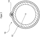
- This pipeline 10 initially comprises an inner load-bearing core tube 11 made of plastic with a lumen through which the medium flows.
- the core tube 11 is surrounded all around by a protective jacket 12, which consists of a plastic material with a higher mechanical strength, higher abrasion resistance, etc.
- This outer protective jacket 12 is extruded onto the core tube 11, for example.
- the outer protective jacket 12 surrounds the core tube almost everywhere without a gap, but a unit of measuring lines 13 in the form of a cable or the like is laid in one or more regions of the circumference.
- This unit of measuring lines 13 is used for resistance measurement for the detection and location of damaged areas and leaks used the invention. For the sake of easier handling in the manufacture of the pipeline 10, these several measuring lines are generally combined in one cable to form a unit 13, but this is not absolutely necessary for the function.
- the mentioned unit of measuring lines 13 is as from Figure 1 It can be seen below the outer casing of the pipeline by the protective jacket 12, so that the unit is also protected against mechanical influences by the protective jacket, but if the protective jacket is damaged, moisture can reach the measuring lines from the outside from the ground.
- the measuring lines 13 are laid on the core tube 11, which simplifies the manufacture of the tube 10, since the core tube 11 can then be extruded first, then the measuring lines 13 can be attached to it, and then the protective jacket 12 extruded so that this both the core tube 11 and also covers the measuring lines 13.
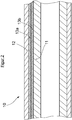
- Figure 2 shows a simplified longitudinal section of a in Figure 1
- the pipeline 10 shown from the front side shows on the one hand the inner core tube 11 and the outer protective jacket 12 applied to this inner core tube 11
- the unit of measuring lines 13 has at least two conductors, namely a first completely insulated conductor 13 a made of a comparatively low-resistance wire such as copper or the like and a second only partially insulated conductor 13 b made of a wire made of a material with a higher specific resistance than the first conductor 13 a, for example made of a chromium-nickel alloy.
- This second electrical conductor 13 b is the actual measuring line and is also referred to hereinafter as a sensor wire.
- the first electrical conductor 13 a serves as a reference line and is also referred to hereinafter as a reference wire.
- Both the sensor wire 13 b and the reference wire 13 a preferably each have an additional feedback wire, which is shown in the schematic drawing Figure 2 is not shown for simplification.
- a unit of measuring lines each has four line wires, of which, however, the sensor wire 13 b and the reference wire 13 a are primarily important for the measuring function. Further details regarding the structure and functioning of the measuring lines will be described later with reference to the enlarged detail views according to the Figures 3 and 4th as well as the schematic representation of Figure 5 described in more detail.
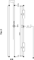
- Figure 3 shows in side view the detail of a single measuring line or sensor wire 13 b.
- This includes electrical insulation 132 consisting of a suitable plastic such as PTFE.
- the sensor wire 13 b has an internal wire 133 made of a comparatively high-resistance metal, for example made of a chromium-nickel alloy NiCr 8020, which for example has a diameter of approximately 0.5 mm.
- the electrical insulation 132 is how to get in Figure 3 interrupted by perforations 131 at several points at regular intervals from each other, so that in the event of damage to the outer protective jacket, moisture from the soil surrounding the pipeline 10 can reach the inner wire 133 of the sensor wire, the resistance of which is measured according to the invention.
- FIG 4 shows in side view in detail a return wire 13 a, which is also referred to herein as the first conductor.
- This return wire 13 a also includes electrical insulation 134 consisting of a suitable plastic and also has an inner wire 135, which in this case, however, consists of a metallic material with comparatively good electrical conductivity, that is, a low-resistance metal such as a copper wire .
- the return wire 13 a has an electrical insulation 134 which completely insulates the wire, so there are no openings in the insulation, so that any moisture that penetrates if the pipeline 10 is damaged can damage the wire 135 Return wire 13 a can not wet.
- Figure 5 shows a variant of the invention in which the pipeline is at least partially, that is to say, for example in individual layers, electrically conductive.
- Monitoring is made possible by an ohmic resistance measurement between the perforated sensor wire 13 b and the pipeline 10 in which the medium flows. Since the two conductors are electrically insulated with an intact pipeline 10 with a protective jacket, there is a high insulation resistance between the sensor wire 13 b and the core tube 11.
- the protective jacket 12 is now damaged when the pipeline 10 is damaged, moisture can penetrate through the perforations 131 in the insulation 132 of the sensor wire 13 b and the resistance between the pipe (media tube) and the sensor wire 13 b is reduced.
- the location of the damaged area can now be carried out according to the principle of the unloaded voltage divider.
- the resistance wire of the sensor wire 13 b forms a series resistance (loop resistance Rges), the size of which is ultimately determined by the length of the tube and the wire resistance built into it.
- a damaged point in the pipe system represents a connection between the sensor wire and the media pipe and divides the loop resistance into sections R (x1) from the start of the pipe (0% of the length) to the fault and section R (x2) from the fault to the pipe end (100 % of length).
- the two partial resistors R (x1) and R (x2) are directly dependent on the location of the moisture penetration. If a voltage is applied to the sensor loop 13 b, in the event of a fault, the conductive moisture transfers a partial voltage value that depends on the location to the media tube. Electrically speaking, the media tube takes over the function of the third connection, similar to the wiper connection of a potentiometer.
- the measured partial tension (x% of the total tension) is directly proportional to the location of the moisture penetration (x% of the total length).
- the advantages of the solution according to the invention are that the entire pipe system can be monitored. No electronic components are required.
- crimp sleeves can be used for simple sleeve assembly.
- Sensor loop monitoring can be carried out over the entire network. The location is possible even with small damaged areas and there is a high sensitivity. Safe and easy location of initial errors is possible.
- the pipe length can easily be determined by loop measurement.
- An arrangement according to the invention with a NiCr wire system as a return wire 13 a can be checked, for example, by measuring the continuity of the wire loop, the value being between 0.1 and 10 kOhm, for example.
- the measured value must correspond to the route length.
- the values in the forward and return should be approximately the same.
- An insulation measurement is also carried out between the wire loop and the media pipe, a high-resistance value in the range of, for example, more than 10 Mohm per 1000 m of pipeline being measured.
- the measurements are preferably carried out using a special insulation measuring device, for example LANCIER monitoring "PipeCheck" or isoplus “IPS-HST” or the like.
- the mode of operation here is similar to that previously used with Figure 5 variant described, but with the difference that the example of Figure 6 is a non-conductive pipeline and therefore the otherwise conductive media pipe is replaced by a conductive reference wire 15.
- the sensor wire 13 b is connected to a return wire 13 a guided in the opposite direction along the pipeline 10 to form a first measuring loop.
- a second measuring loop is formed by a reference wire 15, which is also connected to a return wire 16 guided in the opposite direction along the pipeline 10.
- the conductive reference wire 15 can consist, for example, of a copper wire, which in particular can be tin-plated and coated with a fleece. In order to check the continuity of the reference wire 15, it is connected to an insulated return wire 16 to form a measuring loop, which can be checked for continuity by a measuring device.
- This variant thus results in two measuring loops, the first measuring loop consisting of sensor wire 13 a and return wire 13 b and the second measuring loop consisting of reference wire 15 and return wire 16.
- the first measuring loop consisting of sensor wire 13 a and return wire 13 b
- the second measuring loop consisting of reference wire 15 and return wire 16.
- the reference wire 15 also comes into contact with moisture from the ground.
Landscapes
- Engineering & Computer Science (AREA)
- General Engineering & Computer Science (AREA)
- Physics & Mathematics (AREA)
- General Physics & Mathematics (AREA)
- Mechanical Engineering (AREA)
- Acoustics & Sound (AREA)
- Examining Or Testing Airtightness (AREA)
- Investigating Or Analyzing Materials By The Use Of Electric Means (AREA)
Applications Claiming Priority (1)
| Application Number | Priority Date | Filing Date | Title |
|---|---|---|---|
| DE202018106981.0U DE202018106981U1 (de) | 2018-12-06 | 2018-12-06 | Anordnung umfassend eine Rohrleitung sowie eine Einrichtung zu deren Überwachung |
Publications (2)
| Publication Number | Publication Date |
|---|---|
| EP3663738A2 true EP3663738A2 (fr) | 2020-06-10 |
| EP3663738A3 EP3663738A3 (fr) | 2020-06-24 |
Family
ID=65234954
Family Applications (1)
| Application Number | Title | Priority Date | Filing Date |
|---|---|---|---|
| EP19213922.8A Withdrawn EP3663738A3 (fr) | 2018-12-06 | 2019-12-05 | Agencement comprenant un conduit tubulaire ainsi que dispositif de surveillance d'un tel agencement |
Country Status (2)
| Country | Link |
|---|---|
| EP (1) | EP3663738A3 (fr) |
| DE (1) | DE202018106981U1 (fr) |
Cited By (2)
| Publication number | Priority date | Publication date | Assignee | Title |
|---|---|---|---|---|
| CN118100046A (zh) * | 2024-04-23 | 2024-05-28 | 哈尔滨凯霖信息技术有限公司 | 一种5g通信专用管道 |
| CN120007958A (zh) * | 2025-04-22 | 2025-05-16 | 国网江苏省电力有限公司电力科学研究院 | 一种sf6泄漏识别抗压防破结构及其使用方法 |
Families Citing this family (4)
| Publication number | Priority date | Publication date | Assignee | Title |
|---|---|---|---|---|
| CN110242799B (zh) * | 2019-05-05 | 2020-12-04 | 上海信立生态环境工程有限公司 | 一种应用于非开挖钻机拖拉管的维修施工方法 |
| CN113446520A (zh) * | 2020-03-28 | 2021-09-28 | 五行科技股份有限公司 | 智能管线及其系统 |
| CN113778208B (zh) * | 2021-09-15 | 2024-11-29 | 深圳市英维克科技股份有限公司 | 管道 |
| DE102023103799A1 (de) * | 2023-02-16 | 2024-08-22 | Egeplast International Gmbh | Kunststoffohr für den Medientransport unter lnnendruck mit integrierter Sensorik zur Funktionsüberwachung und Beschädigungsdetektion und Verfahren zur Installation eines derartigen Kunststoffrohrs |
Citations (6)
| Publication number | Priority date | Publication date | Assignee | Title |
|---|---|---|---|---|
| DE3309704A1 (de) | 1983-03-18 | 1984-09-20 | kabelmetal electro GmbH, 3000 Hannover | Vorrichtung zur laufenden ueberwachung eines waermeisolierten leitungsrohres |
| DE19519650C2 (de) | 1995-05-30 | 1997-04-17 | Bernd Brandes | Verfahren zur Ortung undichter Stellen in Rohrleitungen und Rohrleitungssystem, insbesondere für die Übertragung von Fernwärme |
| DE19841317C1 (de) | 1998-09-10 | 2000-02-17 | Dirk Hergenroether | Leckanzeigeeinrichtung für Kunststoffabdichtungen sowie entsprechendes Verfahren zur Leckanzeige |
| WO2004038357A1 (fr) | 2002-10-24 | 2004-05-06 | Körber, Karin | Systeme compose de capteurs servant a detecter et localiser le mouillage de surfaces par des milieux fluides |
| DE102007038297A1 (de) | 2007-08-14 | 2009-02-19 | Egeplast Werner Strumann Gmbh & Co. Kg | Verfahren zur grabenlosen Verlegung mindestens zweier Rohre oder Leitungen |
| DE102012103747A1 (de) | 2012-04-27 | 2013-10-31 | Stadtwerke Rosenheim Gmbh & Co. Kg | Leckage-Überwachungsvorrichtung und Verfahren zur Leckage-Überwachung in einem Fernwärmerohr |
-
2018
- 2018-12-06 DE DE202018106981.0U patent/DE202018106981U1/de active Active
-
2019
- 2019-12-05 EP EP19213922.8A patent/EP3663738A3/fr not_active Withdrawn
Patent Citations (6)
| Publication number | Priority date | Publication date | Assignee | Title |
|---|---|---|---|---|
| DE3309704A1 (de) | 1983-03-18 | 1984-09-20 | kabelmetal electro GmbH, 3000 Hannover | Vorrichtung zur laufenden ueberwachung eines waermeisolierten leitungsrohres |
| DE19519650C2 (de) | 1995-05-30 | 1997-04-17 | Bernd Brandes | Verfahren zur Ortung undichter Stellen in Rohrleitungen und Rohrleitungssystem, insbesondere für die Übertragung von Fernwärme |
| DE19841317C1 (de) | 1998-09-10 | 2000-02-17 | Dirk Hergenroether | Leckanzeigeeinrichtung für Kunststoffabdichtungen sowie entsprechendes Verfahren zur Leckanzeige |
| WO2004038357A1 (fr) | 2002-10-24 | 2004-05-06 | Körber, Karin | Systeme compose de capteurs servant a detecter et localiser le mouillage de surfaces par des milieux fluides |
| DE102007038297A1 (de) | 2007-08-14 | 2009-02-19 | Egeplast Werner Strumann Gmbh & Co. Kg | Verfahren zur grabenlosen Verlegung mindestens zweier Rohre oder Leitungen |
| DE102012103747A1 (de) | 2012-04-27 | 2013-10-31 | Stadtwerke Rosenheim Gmbh & Co. Kg | Leckage-Überwachungsvorrichtung und Verfahren zur Leckage-Überwachung in einem Fernwärmerohr |
Cited By (2)
| Publication number | Priority date | Publication date | Assignee | Title |
|---|---|---|---|---|
| CN118100046A (zh) * | 2024-04-23 | 2024-05-28 | 哈尔滨凯霖信息技术有限公司 | 一种5g通信专用管道 |
| CN120007958A (zh) * | 2025-04-22 | 2025-05-16 | 国网江苏省电力有限公司电力科学研究院 | 一种sf6泄漏识别抗压防破结构及其使用方法 |
Also Published As
| Publication number | Publication date |
|---|---|
| EP3663738A3 (fr) | 2020-06-24 |
| DE202018106981U1 (de) | 2019-01-16 |
Similar Documents
| Publication | Publication Date | Title |
|---|---|---|
| DE202018106981U1 (de) | Anordnung umfassend eine Rohrleitung sowie eine Einrichtung zu deren Überwachung | |
| EP2757359B1 (fr) | Dispositif permettant de déterminer les fuites d'une conduite de liquide, en particulier d'une conduite de liquide sous haute pression | |
| DE202018101539U1 (de) | Vorrichtung zur Ortung einer Leckage an einem fluidführenden Abschnitt | |
| DE102012017415A1 (de) | Verfahren und Vorrichtung zur Überwachung der Wirksamkeit des kathodischen Korrosionsschutzes von im Erdreich verlegten Anlagen aus Metall | |
| EP3282237A1 (fr) | Système de surveillance des fuites pour objets enfermant un espace et régions de couplage intermédiaires et procédé associé | |
| DE4124640C2 (de) | Rohrleitungssystem | |
| DE102017105365A1 (de) | Verfahren und System zur Anzeige des Verschleißes bei Schläuchen | |
| DE102018103909A1 (de) | Anordnung umfassend eine Rohrleitung sowie eine Einrichtung zu deren Überwachung | |
| DE3886011T2 (de) | Sicherheitssystem und ein signaltragendes Glied dafür. | |
| EP2481965B1 (fr) | Faisceau de tuyau en matière synthétique avec conducteur electrique | |
| EP4665995A1 (fr) | Tuyau en plastique pour le transport de milieux sous pression interne avec système de capteur intégré pour la surveillance de fonction et la détection d'endommagement et procédé d'installation d'un tel tuyau en plastique | |
| DE4237477C2 (de) | Rohrförmiges Bauteil mit einer Lecküberwachungseinrichtung und Verfahren zu seiner Herstellung | |
| EP3760905B1 (fr) | Tuyau pourvu de plusieurs conduits de capteur | |
| EP0511343B1 (fr) | Dispositif de surveillance de l'etancheite de canalisations et de structures en matieres thermoplastiques a l'air libre et sous terre | |
| EP1637786B1 (fr) | Dispositif de surveillance et notification de fuites | |
| DE19914658C2 (de) | Anordnung zur Messung von Undichtigkeiten in Abdichtungssystemen zur Leckagedetektion und Leckageortung elektrisch leitender Fluide sowie Verwendung einer solchen Anordnung | |
| EP0902901B1 (fr) | Ruban de signalisation reperable servant a identifier des cables et des conduites notamment non metalliques enfouis dans le sol | |
| DE3232211C2 (de) | Mediumtransportleitung | |
| WO2020064951A1 (fr) | Capteur et système de mesure pour détecter un fluide sur un élément structural muni d'une isolation | |
| DE10257330A1 (de) | Messverfahren zur Früherkennung von eingedrungener Flüssigkeit in lang gestreckten Betriebsmitteln | |
| DE102015104060A1 (de) | Trassenwarnband | |
| EP4187238B1 (fr) | Dispositif et procédé de mesure de l'humidité dans des bâtiments | |
| EP1728895A1 (fr) | Méthode de surveillance pour détecter l'approche d'un corps conductive au pipe-line pour fluides cathodiquement protégée | |
| EP0582725B1 (fr) | Système de tuyauterie pour la détection de fuites | |
| DE2304919C3 (de) | Mit einem Schutzmantel versehene Rohrleitung |
Legal Events
| Date | Code | Title | Description |
|---|---|---|---|
| PUAI | Public reference made under article 153(3) epc to a published international application that has entered the european phase |
Free format text: ORIGINAL CODE: 0009012 |
|
| STAA | Information on the status of an ep patent application or granted ep patent |
Free format text: STATUS: THE APPLICATION HAS BEEN PUBLISHED |
|
| PUAL | Search report despatched |
Free format text: ORIGINAL CODE: 0009013 |
|
| AK | Designated contracting states |
Kind code of ref document: A2 Designated state(s): AL AT BE BG CH CY CZ DE DK EE ES FI FR GB GR HR HU IE IS IT LI LT LU LV MC MK MT NL NO PL PT RO RS SE SI SK SM TR |
|
| AX | Request for extension of the european patent |
Extension state: BA ME |
|
| AK | Designated contracting states |
Kind code of ref document: A3 Designated state(s): AL AT BE BG CH CY CZ DE DK EE ES FI FR GB GR HR HU IE IS IT LI LT LU LV MC MK MT NL NO PL PT RO RS SE SI SK SM TR |
|
| AX | Request for extension of the european patent |
Extension state: BA ME |
|
| RIC1 | Information provided on ipc code assigned before grant |
Ipc: F16L 9/133 20060101ALI20200516BHEP Ipc: F17D 5/06 20060101ALI20200516BHEP Ipc: F16L 11/127 20060101ALI20200516BHEP Ipc: G01M 3/18 20060101AFI20200516BHEP Ipc: G01M 3/40 20060101ALI20200516BHEP |
|
| STAA | Information on the status of an ep patent application or granted ep patent |
Free format text: STATUS: THE APPLICATION IS DEEMED TO BE WITHDRAWN |
|
| 18D | Application deemed to be withdrawn |
Effective date: 20210112 |