EP3663747A1 - Systèmes et procédés d'inspection de canalisations à l'aide d'un robot d'inspection de canalisations - Google Patents
Systèmes et procédés d'inspection de canalisations à l'aide d'un robot d'inspection de canalisations Download PDFInfo
- Publication number
- EP3663747A1 EP3663747A1 EP19212415.4A EP19212415A EP3663747A1 EP 3663747 A1 EP3663747 A1 EP 3663747A1 EP 19212415 A EP19212415 A EP 19212415A EP 3663747 A1 EP3663747 A1 EP 3663747A1
- Authority
- EP
- European Patent Office
- Prior art keywords
- pipeline
- robot
- inspection
- crawler
- motors
- Prior art date
- Legal status (The legal status is an assumption and is not a legal conclusion. Google has not performed a legal analysis and makes no representation as to the accuracy of the status listed.)
- Granted
Links
Images







Classifications
-
- G—PHYSICS
- G01—MEASURING; TESTING
- G01N—INVESTIGATING OR ANALYSING MATERIALS BY DETERMINING THEIR CHEMICAL OR PHYSICAL PROPERTIES
- G01N23/00—Investigating or analysing materials by the use of wave or particle radiation, e.g. X-rays or neutrons, not covered by groups G01N3/00 – G01N17/00, G01N21/00 or G01N22/00
- G01N23/02—Investigating or analysing materials by the use of wave or particle radiation, e.g. X-rays or neutrons, not covered by groups G01N3/00 – G01N17/00, G01N21/00 or G01N22/00 by transmitting the radiation through the material
- G01N23/04—Investigating or analysing materials by the use of wave or particle radiation, e.g. X-rays or neutrons, not covered by groups G01N3/00 – G01N17/00, G01N21/00 or G01N22/00 by transmitting the radiation through the material and forming images of the material
-
- B—PERFORMING OPERATIONS; TRANSPORTING
- B62—LAND VEHICLES FOR TRAVELLING OTHERWISE THAN ON RAILS
- B62D—MOTOR VEHICLES; TRAILERS
- B62D55/00—Endless track vehicles
- B62D55/06—Endless track vehicles with tracks without ground wheels
- B62D55/065—Multi-track vehicles, i.e. more than two tracks
-
- B—PERFORMING OPERATIONS; TRANSPORTING
- B62—LAND VEHICLES FOR TRAVELLING OTHERWISE THAN ON RAILS
- B62D—MOTOR VEHICLES; TRAILERS
- B62D63/00—Motor vehicles or trailers not otherwise provided for
- B62D63/02—Motor vehicles
-
- G—PHYSICS
- G01—MEASURING; TESTING
- G01N—INVESTIGATING OR ANALYSING MATERIALS BY DETERMINING THEIR CHEMICAL OR PHYSICAL PROPERTIES
- G01N21/00—Investigating or analysing materials by the use of optical means, i.e. using sub-millimetre waves, infrared, visible or ultraviolet light
- G01N21/84—Systems specially adapted for particular applications
- G01N21/88—Investigating the presence of flaws or contamination
- G01N21/95—Investigating the presence of flaws or contamination characterised by the material or shape of the object to be examined
- G01N21/954—Inspecting the inner surface of hollow bodies, e.g. bores
-
- G—PHYSICS
- G05—CONTROLLING; REGULATING
- G05D—SYSTEMS FOR CONTROLLING OR REGULATING NON-ELECTRIC VARIABLES
- G05D1/00—Control of position, course, altitude or attitude of land, water, air or space vehicles, e.g. using automatic pilots
- G05D1/0088—Control of position, course, altitude or attitude of land, water, air or space vehicles, e.g. using automatic pilots characterized by the autonomous decision making process, e.g. artificial intelligence, predefined behaviours
-
- G—PHYSICS
- G05—CONTROLLING; REGULATING
- G05D—SYSTEMS FOR CONTROLLING OR REGULATING NON-ELECTRIC VARIABLES
- G05D1/00—Control of position, course, altitude or attitude of land, water, air or space vehicles, e.g. using automatic pilots
- G05D1/20—Control system inputs
- G05D1/22—Command input arrangements
- G05D1/221—Remote-control arrangements
- G05D1/227—Handing over between remote control and on-board control; Handing over between remote control arrangements
-
- G—PHYSICS
- G06—COMPUTING OR CALCULATING; COUNTING
- G06V—IMAGE OR VIDEO RECOGNITION OR UNDERSTANDING
- G06V10/00—Arrangements for image or video recognition or understanding
- G06V10/20—Image preprocessing
- G06V10/24—Aligning, centring, orientation detection or correction of the image
-
- G—PHYSICS
- G01—MEASURING; TESTING
- G01N—INVESTIGATING OR ANALYSING MATERIALS BY DETERMINING THEIR CHEMICAL OR PHYSICAL PROPERTIES
- G01N21/00—Investigating or analysing materials by the use of optical means, i.e. using sub-millimetre waves, infrared, visible or ultraviolet light
- G01N21/84—Systems specially adapted for particular applications
- G01N21/88—Investigating the presence of flaws or contamination
- G01N21/95—Investigating the presence of flaws or contamination characterised by the material or shape of the object to be examined
- G01N21/954—Inspecting the inner surface of hollow bodies, e.g. bores
- G01N2021/9542—Inspecting the inner surface of hollow bodies, e.g. bores using a probe
-
- G—PHYSICS
- G01—MEASURING; TESTING
- G01N—INVESTIGATING OR ANALYSING MATERIALS BY DETERMINING THEIR CHEMICAL OR PHYSICAL PROPERTIES
- G01N2223/00—Investigating materials by wave or particle radiation
- G01N2223/03—Investigating materials by wave or particle radiation by transmission
-
- G—PHYSICS
- G01—MEASURING; TESTING
- G01N—INVESTIGATING OR ANALYSING MATERIALS BY DETERMINING THEIR CHEMICAL OR PHYSICAL PROPERTIES
- G01N2223/00—Investigating materials by wave or particle radiation
- G01N2223/30—Accessories, mechanical or electrical features
- G01N2223/33—Accessories, mechanical or electrical features scanning, i.e. relative motion for measurement of successive object-parts
- G01N2223/3303—Accessories, mechanical or electrical features scanning, i.e. relative motion for measurement of successive object-parts object fixed; source and detector move
-
- G—PHYSICS
- G01—MEASURING; TESTING
- G01N—INVESTIGATING OR ANALYSING MATERIALS BY DETERMINING THEIR CHEMICAL OR PHYSICAL PROPERTIES
- G01N2223/00—Investigating materials by wave or particle radiation
- G01N2223/60—Specific applications or type of materials
- G01N2223/628—Specific applications or type of materials tubes, pipes
-
- G—PHYSICS
- G01—MEASURING; TESTING
- G01N—INVESTIGATING OR ANALYSING MATERIALS BY DETERMINING THEIR CHEMICAL OR PHYSICAL PROPERTIES
- G01N23/00—Investigating or analysing materials by the use of wave or particle radiation, e.g. X-rays or neutrons, not covered by groups G01N3/00 – G01N17/00, G01N21/00 or G01N22/00
- G01N23/02—Investigating or analysing materials by the use of wave or particle radiation, e.g. X-rays or neutrons, not covered by groups G01N3/00 – G01N17/00, G01N21/00 or G01N22/00 by transmitting the radiation through the material
- G01N23/06—Investigating or analysing materials by the use of wave or particle radiation, e.g. X-rays or neutrons, not covered by groups G01N3/00 – G01N17/00, G01N21/00 or G01N22/00 by transmitting the radiation through the material and measuring the absorption
- G01N23/18—Investigating the presence of flaws defects or foreign matter
Definitions
- aspects of the present disclosure relate generally to inspection of above ground pipelines, and more particularly, to systems and methods for creating and utilizing a robot for pipeline inspection.
- CUI corrosion underneath insulation
- Embodiments may include a robotic crawler having a plurality of motors that are individually controllable for improved positioning on the pipeline to facilitate image acquisition.
- Embodiments may also include mounting systems to house and carry imaging equipment configured to capture image data simultaneously from a plurality of angles. Such mounting systems may be adjustable to account for different sizes of pipes (e.g., 2-40+ inches), and may be configured to account for traversing various pipe support structures. Still further, mounting systems may include quick-release members to allow for removal and re-mounting of imaging equipment when traversing support structures. In other aspects, embodiments may also be directed toward control systems for the robotic crawler which assist in the navigation and image capture capabilities of the crawler.
- a pipeline inspection robot may include a housing compartment having one or more drive control systems, imaging control systems, and power supply components.
- the robot may further include a plurality of tracks configured to contact a pipe under inspection and to support the robot on an external surface of the pipe under inspection.
- the robot may include a plurality of motors configured to drive the plurality of tracks, wherein at least two of the plurality of motors are controlled separately by the one or more drive control systems, and at least one mounting component configured to attach one or more imaging components configured to capture imaging data for the pipe inspection.
- a method for inspecting an above-ground pipeline may include one or more of the steps of: mounting an inspection crawler on a pipeline under inspection, said inspection crawler including a plurality of motors configured to drive a plurality of tracks in order to move the crawler; individually controlling the plurality of motors to cause the crawler to traverse the pipeline; adjusting the speed of one or more of the plurality of motors while traversing the pipeline to maintain spatial orientation of the crawler in order to capture image data from a plurality of azimuths; and stopping the plurality of motors and removing the crawler from the pipeline when the inspection imaging data is captured.
- a pipeline inspection robot is disclosed that is configured to convey one or more transmission sources (e.g., X-ray tubes) with one or more detectors (e.g., linear detectors) to capture images of a pipeline.
- the robot also referred to as crawler
- the robot may include a plurality of motors that are individually controlled in order to allow the robot to maintain ideal positioning for the imaging system.
- the robot may include releasable features which allow for the removal and reattachment of imaging components to assist in the inspection process.
- Improvements and advantages exhibited by the pipeline inspection robot include better handling of the robot, the ability to inspect a pipeline with reduced passes of the robot (and in some instances in a single pass), the ability to utilize robotic inspection over pipe support structures, and the ability to releasably attach and detach components to overcome pipeline obstacles encountered during an inspection process.
- a pipeline inspection robot 100 and remote control equipment 150 have various components.
- the pipeline inspection robot 100 may have one or more motors 102, such as motors connected to drive tracks that move the robot to traverse the pipeline.
- the motors may drive other types of traversal mechanisms, such as wheels, hands, feet, claws, teeth, propeller, wing, winch, fin or any other type of mechanism that can be used to motivate traversal of a horizontal or non-horizontal pipeline.
- Motors 102 may also include one or more of encoders or resolvers to provide feedback to control equipment.
- the pipeline inspection robot may have one or more imaging transmission sources 104 (e.g., X-ray tubes) and one or more detectors 106, such as linear detectors (collectively referred to as imaging components). Further, the pipeline inspection robot may have a control box 108.
- imaging transmission sources 104 e.g., X-ray tubes
- detectors 106 such as linear detectors (collectively referred to as imaging components).
- the pipeline inspection robot may have a control box 108.
- Control box 108 of pipeline inspection robot 100 may have various components, such as power supply circuitry 110 and power cleaning circuitry 112 to supply power to other components.
- Power supply circuitry may be connected to an external power or a generator source.
- Inclinometer 114 may be included to sense and correct the relative placement of the robot on the pipeline in such a way that it stays on top of the pipeline and levels, orients, and/or centers the robot automatically throughout traversal of the pipeline.
- Motor controller 116 may operate the motors 102 according to input from the inclinometer and other input from an operator that determines a speed and direction of travel for the robot to both drive the robot and to make orientation corrections to the robot.
- Internal communication circuitry 118 may relay signals between the components of the control box 108.
- a video encoder 120 may be provided with one or more cameras that may be disposed to capture images in an inspection area in a vicinity of the robot. The video encoder 120 may perform some preprocessing of the captured images to encode one or more video streams. Images captured at detectors 106 may be processed and/or encoded by separate processing circuitry within robot 100 or such data may also be processed within video encoder 120.
- imaging data captured at detectors 106 may be remotely processed as discussed in more detail below wither with control box 108 or at a remote station.
- External communication circuitry 122 may provide wired or wireless communication with remote control equipment 150.
- Components of remote control equipment 150 may include a user interface 152 and image data storage 154.
- user interface 152 may have a control interface 156 for controlling movement of the robot, and an image acquisition interface 158 that controls acquisition of image data 162 acquired by the robot, display of the image data 162 in a scrolling fashion, and conversion of the acquired image data into a static image, such as a Digital Imaging and Communication in Non-Destructive Evaluation (DICONDE) static image 164.
- DICONDE Digital Imaging and Communication in Non-Destructive Evaluation
- user interface 152 may include components 160 for processing and/or analyzing the static image.
- the illustrated interfaces comprise custom designed robot control software and image acquisition and display software.
- the robot control software using feedback from the motor encoders or resolvers, axle encoders and inclinometer controls speed and position of the robot on the pipeline and precisely matches the speed of the robot with the acquisition speed of a linear detector. It may also precisely index distance if a field array is used.
- the method includes mounting the robot on the pipeline under inspection.
- the method includes controlling a plurality of motors to cause the robot to traverse the pipeline. In some embodiments, there may be four separate motors disposed to control each track of the robot. In yet another embodiment, two separate motors may control a left and right set or a front and back set of tracks on the robot.
- the method includes adjusting the speed of respective motors to maintain proper robot orientation above the pipeline under inspection. It is appreciated that these motors may be individually controlled in order to steer the robot and maintain proper orientation over the pipeline to facilitate imaging. Such control of directional movement may occur in response to one or more user interface inputs as described herein. Adjustments may be implemented in response to one or more feedback sources. For example, one or more sensors may be disposed on the robot (e.g. inclinometers) that provides feedback to various control systems and causes adjustments to take place. Additionally, as described above, one or more cameras may be disposed on the robot which allows a user to observe the inspection environment and steer the robot as needed.
- sensors may be disposed on the robot (e.g. inclinometers) that provides feedback to various control systems and causes adjustments to take place.
- one or more cameras may be disposed on the robot which allows a user to observe the inspection environment and steer the robot as needed.
- sensors e.g., optic, infrared, and the like
- Adjustments implemented in block 206 may be undertaken automatically in response to feedback processing, manually by the user, or by a combination of both.
- the method includes acquiring image data by capturing images from two or more azimuths.
- a user may receive real-time image capture results which are transmitted between control box 150 and remote control 154. Further, a user may control the speed of the directional movement of the robot during a capture phase. The speed may be controlled automatically, or based on user interface inputs under control of a skilled operator contemporaneously viewing the displayed image capture results. For example, a user may determine how many milliseconds per line the detector captures, and then the software controls the speed of the robot accordingly.
- the image capture results may be displayed in a scrolling fashion to permit the operator to observe the contrast of the acquired image data. Accordingly, the operator is enabled to adjust the speed based on the observed contrast to obtain a desired level of contrast in the image data.
- the method may optionally include detachably removing one or more imaging components in order to traverse one or more pipeline support structures.
- a robot may be required to pass a pipeline support which is contacting the pipeline on the underneath side of the pipeline.
- embodiments may provide a user with a quick means (e.g. quick release bolts, tabs, picatinny rail mounts, etc.) to detach a component and allow the robot to traverse the impacted area, and then reattach the component for continued inspection.
- a quick means e.g. quick release bolts, tabs, picatinny rail mounts, etc.
- the method may include traversing one or more pipe support structures while continuing the inspection scanning. It is notable that in this embodiment, the imaging components are disposed and configured such that the multiple scanning angles may be imaged while traversing a pipe support structure. Such a capability greatly increases the efficiency of a scan and has not been previously available in prior devices.
- the method may include stopping the motors and removing the robot from the pipeline under inspection. This deactivation may also include the deactivation of the one or more transmission sources while stopping of the directional movement of the robot, and may occur in response to one or more user interface inputs as described above.
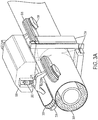
- an embodiment of a pipeline inspection robot may be configured with tracks 305 for traversing pipeline 304.
- each of the tracks 305 may have an independent motor 306 to control speed and direction of the individual track 305.
- a pair of axle position encoders 302 may provide an axle angle data to a controller inside control box/housing component 300, which individually controls motors 306 and may function to automatically level and/or center the robot on top of the pipeline 304.
- control box 300 may house one or more X-ray tubes, such as a pair of 60 kV 12W X-ray tubes. These tubes serve as radiation sources 310, as do additional radiation sources 310 provided on a downwardly extended member 312. Together, these radiation sources 310 produce X-ray beams 308 along more than one azimuth. For example, the sources 310 are arranged so that the beams 308 are directed along tangents to a circle that resides inside the insulation and/or wall of the pipeline 304.
- a pair of linear detectors 308 are arranged on perpendicular members that extend down beside and underneath the pipeline 304 to receive the radiation from the beams, and each sensor array of each detector is divided into two sensor array sections 314 and 316 that produce separate imaging streams so that four images are captured contemporaneously.
- the linear detector was selected which has an 800 micron pixel pitch in order to obtain sufficient resolution and sensitivity for the current embodiment, however other types of detectors may be utilized which provide performance suitable for the needs of the particular project.
- Each image stream provides a side view of a quadrant of the insulated pipeline 304. Although four beams, four azimuths, and four array sections are shown, it should be understood that other embodiments may have more or less (e.g., 2) azimuths, beams, and array sections depending on particular inspection needs.
- embodiments have one or more of the perpendicular members on which the linear detectors are arranged may quickly detach from and reattach to the robot to permit traversal of a support member of the pipeline 304 as discussed above.
- the member that supports the linear detector arranged beneath the pipeline may be reattachably detachable so that a pipeline support member may be cleared during traversal of the robot or so that the robot may be removed from the pipeline 304.
- the member that extends down beside the pipeline may detachably detach form the robot, which accomplishes removal of both detectors.
- detectors 308 and sources 310 may be configured such that the robot may traverse support members without stopping the inspection scanning.
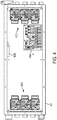
- FIG. 4 provides a schematic of some of the internal components, specifically PCB interconnect board 400A, inclinometer 400B, and motor controllers 400C-400D, of data interface unit 402, which may correspond to a part of control box 100 (see FIG. 1 ). It is appreciated that the illustrated components may be separated or combined with the functionality of other control/processing components. For example, a single processing unit may be provided which handles all of the control processing and interconnection of the component parts of the robot. The arrangement of these components corresponds to the arrangement of external components shown in FIGS. 5 and 6 ..
- one rear end of the data interface unit has ports for an Ethernet umbilical 602, a track rear left control cable 604, a track rear right control cable 606, an encoder rear signal line 608, a camera rear signal line 610, and a DC power input 612.
- an front end of the data interface unit has ports for a detector data and power connection 614, track front left control cable 616, a track front right control cable 618, an encoder front signal line 620, and a camera front signal line 622.
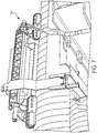
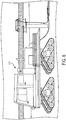
- a cable bundle 700 (see FIG. 7 ) provides signal exchange between the robot and a vehicle 800 (see FIG. 8 ) housing remote control equipment, such as a robot movement control screen and an image acquisition screen. It is envisioned that other embodiments may have wireless communication between the data interface unit and the remote control equipment. Further, one or more power sources may be located onboard the robot to further facilitate wireless use.
- user interface components for controlling movement of a pipeline inspection robot may have one or more display regions 1000 to display video streams of the inspection area and controls 1002 for turning the streams and/or corresponding cameras on and off. These display areas/cameras may be oriented in a plurality of directions. In the illustrated embodiment a front and rear view are shown. It is appreciated that other views and cameras may be available, e.g. looking directionally left, right, and downward at different points on the robot.
- Another control 1004 governs forward or reverse direction of travel of the robot, while control 1006 permits the operator to recenter an axle of the robot.
- Controls 108 permit the operator to start and stop the movement of the robot, while additional controls 1010 allow the operator to control speed of the robot, check status of the robot, configure manual inputs, and/or configure an automated mode that allows the operator to control the robot from a mobile device.
- Display regions 1012 provide data to the operator, such as distance travelled, crawler angle, and axle steering angles. It is appreciated that any additional controls to implement the functionality described herein may also be provided.
- the cameras described above may be useful to an operator to help move the robot and maintain the spatial orientation of the robot in order to capture effective imaging data. In some embodiments such assistance to a user may be provided with other types of sensor data (e.g. electromagnetic imaging such as IR, Radar, and the like, ultrasound, etc.).
- These sensor-based assistance measures may utilize processing circuitry discussed above and provide feedback signals to steer the robot automatically. Additionally, and alternatively, the feedback may be provided to a user interface in a manner that allows a user to monitor conditions and data from said sensors. It is further appreciated that each of these methods may be utilized individually or in combination to facilitate the functionality of the robot.
- user interface components for controlling image data acquisition by the robot include inputs for imaging parameters, scanning details, calibration information, and scrolling display configuration.
- Display regions 1102 and 1104 provide a live energy line and a waterfall plot.
- Scrolling mode the image is displayed as it is acquired. Once the acquisition is complete, the image is displayed in the image viewer window 1200 (see FIG. 11 ).
- a scrolling display region 1300 provides a scrolling display of the image data as it is acquired.
- Detector calibration control 1302 may be used to calibrate the detectors, and a window/level control 1304 may be used to adjust brightness and contrast of the images (which may include adjusting the speed of the robot to allow for more or less exposure on a particular area of pipe).
- Detector settings may be observed and controlled by component 1306, and a scan may be started or stopped by controls 1308.
- In the detector settings window a user may change various settings to optimize the system. For example, a user may change Pixel Binning settings to combine pixels together which may increase signal sensitivity but decrease resolution.
- Lines per second settings allows a user to control the speed of acquisition.
- RCX beginning position and End position settings allows a user to choose a section of detector to use.
- Control 1310 may specify a length of the scan, which may cause the scan to end automatically once the specified length of traversal is completed.
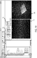
- the user interface may have various controls for displaying and processing a static image after the image data is acquired.
- the static image is a 2D image that may have different tools and filters applied to change the way the image is viewed and/or oriented without changing the basic characteristics of the image.
- the image may be viewed in negative or positive modes.
- various controls 1400 enable a user to window/level, invert, rotate, and adjust the image for presentation.
- a user may also perform a spatial calibration to measure indications in the image. Grayscale intensity readings in different regions may also allow a user to calculate density differences.
- various controls 1500 enable a user to apply various filters to the image, such as an emboss filter, as shown in FIG. 16 .
- various controls 1700 enable a user to choose measurement units and annotate the image.
- areas of higher density which are the lead numbers and image quality indicators and areas of lower density (the dark areas) indicating pitting in the pipe wall.
- the evenly spaced lighter lines are the overlapped seams in the spiral wrapped insulation jacketing.
- the images provided herein are of spiral wrapped insulated pipe and the dark areas displayed indicate pitting in the pipe wall, the darker the area the more wall loss there is.
- the perpendicular lighter bands at regular intervals are the overlapped seams in the insulation wrapping.
- the plot in Fig. 17 allows the user to measure grayscale levels along the line giving the user to determine the amount of wall loss.
- the user interface may also have various controls 1800 under an analysis tab that enable a user to analyze the image.
- the user may generate a plot 1802 of greyscale levels along a profile line 1804.
- an area measurement tool may enable the user to measure an area of the image.
- the functional blocks and modules described herein may comprise processors, electronics devices, hardware devices, electronics components, logical circuits, memories, software codes, firmware codes, etc., or any combination thereof.
- DSP digital signal processor
- ASIC application specific integrated circuit
- FPGA field programmable gate array
- a general-purpose processor may be a microprocessor, but in the alternative, the processor may be any conventional processor, controller, microcontroller, or state machine.
- a processor may also be implemented as a combination of computing devices, e.g., a combination of a DSP and a microprocessor, a plurality of microprocessors, one or more microprocessors in conjunction with a DSP core, or any other such configuration.
- a software module may reside in RAM memory, flash memory, ROM memory, EPROM memory, EEPROM memory, registers, hard disk, a removable disk, a CD-ROM, or any other form of storage medium known in the art.
- An exemplary storage medium is coupled to the processor such that the processor can read information from, and write information to, the storage medium.
- the storage medium may be integral to the processor.
- the processor and the storage medium may reside in an ASIC.
- the ASIC may reside in a user terminal.
- the processor and the storage medium may reside as discrete components in a user terminal.
- the functions described may be implemented in hardware, software, firmware, or any combination thereof. If implemented in software, the functions may be stored on or transmitted over as one or more instructions or code on a computer-readable medium.
- Computer-readable media includes both computer storage media and communication media including any medium that facilitates transfer of a computer program from one place to another. Computer-readable storage media may be any available media that can be accessed by a general purpose or special purpose computer.
- such computer-readable media can comprise RAM, ROM, EEPROM, CD-ROM or other optical disk storage, magnetic disk storage or other magnetic storage devices, or any other medium that can be used to carry or store desired program code means in the form of instructions or data structures and that can be accessed by a general-purpose or special-purpose computer, or a general-purpose or special-purpose processor.
- a connection may be properly termed a computer-readable medium.
- the software is transmitted from a website, server, or other remote source using a coaxial cable, fiber optic cable, twisted pair, or digital subscriber line (DSL), then the coaxial cable, fiber optic cable, twisted pair, or DSL, are included in the definition of medium.
- DSL digital subscriber line
- Disk and disc includes compact disc (CD), laser disc, optical disc, digital versatile disc (DVD), hard disk, solid state disk, and blu-ray disc where disks usually reproduce data magnetically, while discs reproduce data optically with lasers. Combinations of the above should also be included within the scope of computer-readable media.
- the term "and/or,” when used in a list of two or more items, means that any one of the listed items can be employed by itself, or any combination of two or more of the listed items can be employed.
- the composition can contain A alone; B alone; C alone; A and B in combination; A and C in combination; B and C in combination; or A, B, and C in combination.
Landscapes
- Engineering & Computer Science (AREA)
- Physics & Mathematics (AREA)
- General Physics & Mathematics (AREA)
- Chemical & Material Sciences (AREA)
- Health & Medical Sciences (AREA)
- Pathology (AREA)
- Immunology (AREA)
- General Health & Medical Sciences (AREA)
- Biochemistry (AREA)
- Analytical Chemistry (AREA)
- Life Sciences & Earth Sciences (AREA)
- Aviation & Aerospace Engineering (AREA)
- Automation & Control Theory (AREA)
- Radar, Positioning & Navigation (AREA)
- Remote Sensing (AREA)
- Combustion & Propulsion (AREA)
- Mechanical Engineering (AREA)
- Transportation (AREA)
- Game Theory and Decision Science (AREA)
- Business, Economics & Management (AREA)
- Artificial Intelligence (AREA)
- Evolutionary Computation (AREA)
- Medical Informatics (AREA)
- Multimedia (AREA)
- Theoretical Computer Science (AREA)
- Manipulator (AREA)
Applications Claiming Priority (1)
| Application Number | Priority Date | Filing Date | Title |
|---|---|---|---|
| US16/208,466 US11143599B2 (en) | 2018-12-03 | 2018-12-03 | Systems and methods for inspecting pipelines using a pipeline inspection robot |
Publications (3)
| Publication Number | Publication Date |
|---|---|
| EP3663747A1 true EP3663747A1 (fr) | 2020-06-10 |
| EP3663747C0 EP3663747C0 (fr) | 2025-09-24 |
| EP3663747B1 EP3663747B1 (fr) | 2025-09-24 |
Family
ID=68807986
Family Applications (1)
| Application Number | Title | Priority Date | Filing Date |
|---|---|---|---|
| EP19212415.4A Active EP3663747B1 (fr) | 2018-12-03 | 2019-11-29 | Systèmes et procédés d'inspection de canalisations à l'aide d'un robot d'inspection de canalisations |
Country Status (3)
| Country | Link |
|---|---|
| US (3) | US11143599B2 (fr) |
| EP (1) | EP3663747B1 (fr) |
| CA (1) | CA3063259A1 (fr) |
Cited By (4)
| Publication number | Priority date | Publication date | Assignee | Title |
|---|---|---|---|---|
| CN114060731A (zh) * | 2021-11-23 | 2022-02-18 | 重庆大学 | 腐蚀位移形变融合监测终端及管道腐蚀位移形变监测系统和方法 |
| WO2022072541A3 (fr) * | 2020-09-29 | 2022-04-28 | Varex Imaging Corporation | Système d'inspection radiographique pour tuyaux et autres structures et estimation de perte de matériau |
| EP4040107A1 (fr) * | 2021-02-08 | 2022-08-10 | Baker Hughes Oilfield Operations LLC | Reconnaissance assistée de la corrosion et de l'érosion |
| US11668660B2 (en) | 2020-09-29 | 2023-06-06 | Varex Imaging Corporation | Radiographic inspection system for pipes and other structures and material loss estimation |
Families Citing this family (13)
| Publication number | Priority date | Publication date | Assignee | Title |
|---|---|---|---|---|
| CN111737313A (zh) * | 2020-06-12 | 2020-10-02 | 济南市市政工程设计研究院(集团)有限责任公司 | 一种地下综合管廊的监控系统 |
| US12280860B2 (en) * | 2020-12-22 | 2025-04-22 | Petroleo Brasil S.A.—Petrobras | Subsea robot and method for detecting norm breakdown in a production system |
| US11118719B1 (en) * | 2021-02-22 | 2021-09-14 | Kakivik Asset Management, LLC | Pipeline inspection device |
| US20220268393A1 (en) * | 2021-02-22 | 2022-08-25 | Kakivik Asset Management, LLC | Pipeline Inspection Device |
| CN113190019B (zh) * | 2021-05-26 | 2023-05-16 | 立得空间信息技术股份有限公司 | 一种基于虚拟仿真的巡检机器人任务点布置方法及系统 |
| CN113191336B (zh) * | 2021-06-04 | 2022-01-14 | 绍兴建元电力集团有限公司 | 基于图像识别的电力隐患识别方法及系统 |
| CN114352844B (zh) * | 2022-01-14 | 2023-07-14 | 广州大学 | 一种多功能轻型软体机器人 |
| US12363251B2 (en) * | 2022-08-08 | 2025-07-15 | SeeScan, Inc. | Systems and methods for inspection animation |
| CN115598784B (zh) * | 2022-10-25 | 2026-01-20 | 湖北三江航天红阳机电有限公司 | 一种用于在役管道的绕线机 |
| US20250129877A1 (en) * | 2023-10-23 | 2025-04-24 | BrightAI Corporation | Systems and associated methods for multi-sensor robotic operation |
| CN117630034B (zh) * | 2023-11-13 | 2024-05-24 | 湖南金航船舶制造有限公司 | 一种移动式集装箱船焊缝检测装置及方法 |
| CN117434084A (zh) * | 2023-12-06 | 2024-01-23 | 四川万圣通实业有限公司 | 一种钢管的数字化检测装置及检测方法 |
| WO2026044380A1 (fr) * | 2024-08-29 | 2026-03-05 | Petrogal Brasil S.A. | Dispositif pour inspection dans des conduits souples et procédé d'inspection de conduits souples |
Citations (4)
| Publication number | Priority date | Publication date | Assignee | Title |
|---|---|---|---|---|
| US20070000406A1 (en) * | 2005-06-29 | 2007-01-04 | Arizona Public Service Company | Self-propelled vehicle for movement within a tubular member |
| US20090120215A1 (en) * | 2007-11-08 | 2009-05-14 | Fabtec Solutions, Llc | Crawler for inspecting pipes |
| US20140146161A1 (en) * | 2012-11-26 | 2014-05-29 | Saudi Arabian Oil Company | Outer surface inspecting robot with flipping over flange mechanism |
| CN106094617A (zh) * | 2016-06-20 | 2016-11-09 | 江苏若博机器人科技有限公司 | 无线传输三核八轴履带式高速天然气管道机器人控制系统 |
Family Cites Families (60)
| Publication number | Priority date | Publication date | Assignee | Title |
|---|---|---|---|---|
| US3495626A (en) | 1967-10-18 | 1970-02-17 | American Mach & Foundry | Pipeline plugging apparatus and methods |
| DE69330513D1 (de) | 1992-03-20 | 2001-09-06 | Commw Scient Ind Res Org | Gegenstands-überwachungsystem |
| JP3296648B2 (ja) * | 1993-11-30 | 2002-07-02 | 三洋電機株式会社 | ディジタル音程変換における不連続点の改善処理方法およびその装置 |
| US5698854A (en) | 1996-05-20 | 1997-12-16 | Omega International Technology, Inc. | Method and apparatus for inspecting pipes |
| US5857534A (en) | 1997-06-05 | 1999-01-12 | Kansas State University Research Foundation | Robotic inspection apparatus and method |
| JPH11194101A (ja) | 1998-01-06 | 1999-07-21 | Hitachi Eng & Service Co Ltd | 配管用ct撮影装置並びにシリコン酸化物堆積監視方法 |
| US5963030A (en) | 1998-03-30 | 1999-10-05 | Union Oil Company Of California | Pipe inspection apparatus and process |
| US7672022B1 (en) | 2000-04-07 | 2010-03-02 | Hewlett-Packard Development Company, L.P. | Methods and apparatus for analyzing an image |
| KR100478251B1 (ko) | 2002-06-28 | 2005-03-22 | 한국기계연구원 | 보온재 부착 파이프라인의 부식두께 측정장치 |
| US6891477B2 (en) | 2003-04-23 | 2005-05-10 | Baker Hughes Incorporated | Apparatus and methods for remote monitoring of flow conduits |
| US6925145B2 (en) | 2003-08-22 | 2005-08-02 | General Electric Company | High speed digital radiographic inspection of piping |
| US7077020B2 (en) | 2004-04-01 | 2006-07-18 | Crts, Inc. | Internal field joint inspection robot |
| US7319738B2 (en) | 2004-10-08 | 2008-01-15 | General Electric Company | Delivering X-ray systems to pipe installations |
| EP2167995A2 (fr) | 2007-07-19 | 2010-03-31 | Water Resources Engineering Corporation | Appareil pour acquérir des informations géométriques tridimensionnelles de tuyaux souterrains et odomètre sans contact utilisant un détecteur de flux optique et utilisation de ceux-ci |
| US7656997B1 (en) | 2008-09-15 | 2010-02-02 | VJ Technologies | Method and apparatus for automated, digital, radiographic inspection of piping |
| DE112009002256T5 (de) | 2008-09-19 | 2011-09-29 | Analogic Corporation | Inspektion einer Pipeline |
| PT2352981E (pt) * | 2008-11-03 | 2015-08-27 | Redzone Robotics Inc | Dispositivo para inspeção de cano e método de utilização do mesmo |
| CZ2009480A3 (cs) | 2009-07-24 | 2010-11-24 | Ceské vysoké ucení technické v Praze - Fakulta elektrotechnická | Robot pro cištení a inspekci potrubí a ovládací jednotka pro jeho rízení |
| US8289291B2 (en) | 2009-07-29 | 2012-10-16 | Empire Technology Development Llc | Tactile display control |
| WO2011080590A2 (fr) | 2009-12-30 | 2011-07-07 | Sewervue Technology Corp. | Appareil et procédé d'inspection de conduites d'égout souterraines |
| JP5477853B2 (ja) | 2010-01-19 | 2014-04-23 | 株式会社庄内クリエート工業 | ラインセンサーカメラを用いたx線検査装置 |
| CN103459099B (zh) | 2011-01-28 | 2015-08-26 | 英塔茨科技公司 | 与一个可移动的远程机器人相互交流 |
| US8633713B2 (en) | 2011-04-11 | 2014-01-21 | Crts, Inc. | Internal pipe coating inspection robot |
| EP2718741A1 (fr) | 2011-06-08 | 2014-04-16 | ShawCor Ltd. | Appareil robotique de contrôle intérieur ultrasonique automatisé de soudures circonférentielles de pipelines |
| KR101231910B1 (ko) | 2011-07-13 | 2013-02-08 | 한국전력기술 주식회사 | 배관검사장치 및 이를 이용한 배관검사방법 |
| US8800396B2 (en) | 2011-07-14 | 2014-08-12 | Crts, Inc. | Pipeline internal field joint cleaning, coating, and inspection robot |
| US9146546B2 (en) | 2012-06-04 | 2015-09-29 | Brain Corporation | Systems and apparatus for implementing task-specific learning using spiking neurons |
| KR101290794B1 (ko) | 2012-03-30 | 2013-07-30 | 삼성중공업 주식회사 | 파이프라인 검사용 로봇장치 및 이를 이용한 파이프라인 검사방법 |
| WO2014098068A1 (fr) | 2012-12-18 | 2014-06-26 | 株式会社移動ロボット研究所 | Robot d'inspection de tuyau, et procédé d'inspection de tuyau |
| US20140207406A1 (en) | 2013-01-22 | 2014-07-24 | General Electric Company | Self-directed inspection plan |
| WO2015024118A1 (fr) * | 2013-08-18 | 2015-02-26 | Illusense Inc. | Systèmes et procédés pour le balayage optique de conduites de transport de fluide |
| BR112015007089B1 (pt) | 2013-10-17 | 2021-09-28 | Petróleo Brasileiro S.A. / Petrobras | Equipamento de gamagrafia submarina operado por rov |
| GB2519955B (en) | 2013-11-01 | 2015-09-30 | Paragon Inspection Ltd | Apparatus and method for radiological pipe inspection |
| WO2015081135A1 (fr) | 2013-11-30 | 2015-06-04 | Saudi Arabian Oil Company | Véhicule mobile d'inspection modulaire |
| EP3143387B1 (fr) | 2014-05-13 | 2020-12-16 | Giatec Scientific Ltd. | Procédés et systèmes électriques pour essais sur béton |
| WO2016005893A1 (fr) | 2014-07-08 | 2016-01-14 | Basf Se | Détecteur pour déterminer une position d'au moins un objet |
| US9753150B2 (en) | 2014-09-23 | 2017-09-05 | Sharpxview AS | Low-rate inexpensive digital γ-ray imaging/inspection system |
| WO2016049645A1 (fr) | 2014-09-26 | 2016-03-31 | Delta Subsea, Llc | Systèmes, appareil et procédés d'inspection de surfaces immergées |
| US9945092B2 (en) | 2014-12-19 | 2018-04-17 | Ulc Robotics, Inc. | System and method for utility maintenance |
| WO2016176480A1 (fr) * | 2015-04-28 | 2016-11-03 | Delta Subsea Llc | Systèmes, appareils et procédés pour surveiller des conduites sous-marines |
| EP3106734B1 (fr) | 2015-06-19 | 2020-06-03 | ULC Robotics, Inc. | Système de lancement pour une canalisation sous pression |
| JP5963030B2 (ja) | 2015-08-05 | 2016-08-03 | フリュー株式会社 | 画像処理装置、画像処理方法、及びプログラム |
| MX362305B (es) | 2015-11-06 | 2018-11-21 | Corporacion Mexicana De Investigacion En Mat S A De C V | Aparato para inspección de corrosión externa de tuberías. |
| GB2544529A (en) * | 2015-11-20 | 2017-05-24 | Nat Grid Gas Plc | Pipeline inspection robot |
| US20170191601A1 (en) | 2016-01-04 | 2017-07-06 | Veysel Firat Sever | Pipeline Inspection Device |
| WO2017205597A1 (fr) | 2016-05-25 | 2017-11-30 | Gopro, Inc. | Indices de codage sur la base d'un traitement de signal d'images pour l'estimation de mouvement |
| US9927354B1 (en) | 2016-09-28 | 2018-03-27 | Redzone Robotics, Inc. | Method and apparatus for pipe imaging with chemical analysis |
| WO2018064159A1 (fr) | 2016-09-28 | 2018-04-05 | Redzone Robotics, Inc. | Dispositifs, produits et procédés d'imagerie et d'inspection de tuyau |
| JP6500887B2 (ja) | 2016-12-26 | 2019-04-17 | トヨタ自動車株式会社 | 車両用注意喚起装置 |
| CN110226184B (zh) | 2016-12-27 | 2023-07-14 | 杰拉德·迪尔克·施密茨 | 用于机器感知的系统和方法 |
| JP6454676B2 (ja) | 2016-12-28 | 2019-01-16 | 株式会社移動ロボット研究所 | 配管検査用ロボット |
| GB201711412D0 (en) * | 2016-12-30 | 2017-08-30 | Maxu Tech Inc | Early entry |
| WO2018136769A1 (fr) | 2017-01-19 | 2018-07-26 | Aegion Coating Services, Llc | Inspection de joint de tuyau |
| US11719818B2 (en) | 2017-03-16 | 2023-08-08 | Trinamix Gmbh | Detector for optically detecting at least one object |
| CN107339546B (zh) | 2017-07-17 | 2019-06-14 | 浙江金马逊机械有限公司 | 一种自行式管道内壁检修系统以及检修方法 |
| ES2928909T3 (es) * | 2017-09-19 | 2022-11-23 | Arix Tech Inc | Aparato y métodos para recorrer tuberías |
| US10970552B2 (en) | 2017-09-28 | 2021-04-06 | Gopro, Inc. | Scene classification for image processing |
| CN207983366U (zh) | 2017-12-26 | 2018-10-19 | 扬州知的知识产权服务有限公司 | 一种管道内检测加工用工程机械车 |
| CN108488539B (zh) | 2018-03-12 | 2020-04-28 | 西安交通大学 | 主动自适应管径变化的周布履带轮式管道检测机器人 |
| CN108693535B (zh) | 2018-04-03 | 2021-05-18 | 中信重工开诚智能装备有限公司 | 一种用于水下机器人的障碍物探测系统和探测方法 |
-
2018
- 2018-12-03 US US16/208,466 patent/US11143599B2/en active Active
-
2019
- 2019-11-28 CA CA3063259A patent/CA3063259A1/fr active Pending
- 2019-11-29 EP EP19212415.4A patent/EP3663747B1/fr active Active
-
2021
- 2021-10-11 US US17/498,097 patent/US11635391B2/en active Active
-
2023
- 2023-03-17 US US18/123,253 patent/US11946882B2/en active Active
Patent Citations (4)
| Publication number | Priority date | Publication date | Assignee | Title |
|---|---|---|---|---|
| US20070000406A1 (en) * | 2005-06-29 | 2007-01-04 | Arizona Public Service Company | Self-propelled vehicle for movement within a tubular member |
| US20090120215A1 (en) * | 2007-11-08 | 2009-05-14 | Fabtec Solutions, Llc | Crawler for inspecting pipes |
| US20140146161A1 (en) * | 2012-11-26 | 2014-05-29 | Saudi Arabian Oil Company | Outer surface inspecting robot with flipping over flange mechanism |
| CN106094617A (zh) * | 2016-06-20 | 2016-11-09 | 江苏若博机器人科技有限公司 | 无线传输三核八轴履带式高速天然气管道机器人控制系统 |
Non-Patent Citations (1)
| Title |
|---|
| TOSHIHIRO YUKAWA ET AL: "Magnetic Part Design of Pipe-Surface Inspection Robot", IEEE INDUSTRIAL ELECTRONICS, IECON 2006 - 32ND ANNUAL CONFERENCE ON, IEEE, PISCATAWAY, NJ, USA, 1 November 2006 (2006-11-01), pages 3957 - 3962, XP031076914, ISBN: 978-1-4244-0135-2 * |
Cited By (7)
| Publication number | Priority date | Publication date | Assignee | Title |
|---|---|---|---|---|
| WO2022072541A3 (fr) * | 2020-09-29 | 2022-04-28 | Varex Imaging Corporation | Système d'inspection radiographique pour tuyaux et autres structures et estimation de perte de matériau |
| US11668660B2 (en) | 2020-09-29 | 2023-06-06 | Varex Imaging Corporation | Radiographic inspection system for pipes and other structures and material loss estimation |
| JP2023544304A (ja) * | 2020-09-29 | 2023-10-23 | ヴァレックス イメージング コーポレイション | パイプ及びその他の構造の放射線検査システムと材料損失の推定 |
| US11821850B2 (en) | 2020-09-29 | 2023-11-21 | Varex Imaging Corporation | Radiographic inspection system for pipes and other structures and material loss estimation |
| EP4040107A1 (fr) * | 2021-02-08 | 2022-08-10 | Baker Hughes Oilfield Operations LLC | Reconnaissance assistée de la corrosion et de l'érosion |
| CN114060731A (zh) * | 2021-11-23 | 2022-02-18 | 重庆大学 | 腐蚀位移形变融合监测终端及管道腐蚀位移形变监测系统和方法 |
| CN114060731B (zh) * | 2021-11-23 | 2024-01-26 | 重庆大学 | 腐蚀位移形变融合监测终端及管道腐蚀位移形变监测系统和方法 |
Also Published As
| Publication number | Publication date |
|---|---|
| EP3663747C0 (fr) | 2025-09-24 |
| US20220026374A1 (en) | 2022-01-27 |
| US11635391B2 (en) | 2023-04-25 |
| US11143599B2 (en) | 2021-10-12 |
| CA3063259A1 (fr) | 2020-06-03 |
| EP3663747B1 (fr) | 2025-09-24 |
| US11946882B2 (en) | 2024-04-02 |
| US20230228694A1 (en) | 2023-07-20 |
| US20200173935A1 (en) | 2020-06-04 |
Similar Documents
| Publication | Publication Date | Title |
|---|---|---|
| US11946882B2 (en) | Systems and methods for inspecting pipelines using a pipeline inspection robot | |
| US11887291B2 (en) | Systems and methods for inspecting pipelines using a robotic imaging system | |
| US10890505B2 (en) | Systems and methods for inspecting pipelines using a robotic imaging system | |
| US7460980B2 (en) | Method for the control of a pipe inspection system and for the evaluation of the inspection data | |
| EP3798622B1 (fr) | Systèmes et procédés d'inspection de canalisations à l'aide d'un système d'imagerie robotique | |
| CN107718046A (zh) | 用于水下焊接的机器人、机器人系统及作业方法 | |
| CN111412342A (zh) | 管道检测机器人及管道检测方法 | |
| JP6726885B2 (ja) | 検査用カメラおよびこれを備えた検査システム、検査方法 | |
| JP2011231602A (ja) | 構造物の点検装置 | |
| CN106772395A (zh) | 一种核电站取水隧洞水下成像检测装置 | |
| CN207593836U (zh) | 用于水下焊接的机器人 | |
| JP4799088B2 (ja) | 遠隔検査における作業位置計測方法およびその装置 | |
| JP6329445B2 (ja) | 配管内部点検装置 | |
| CN117259975B (zh) | 基于视觉传感的局部干法水下坡口激光填丝焊接装置及方法 | |
| JP4089015B2 (ja) | ボイラ火炉壁の溶射被膜亀裂検出装置 | |
| WO2017057356A1 (fr) | Appareil d'imagerie de structure, appareil d'inspection de structure et système d'inspection de structure | |
| CN116840265A (zh) | 一种基于激光切片法的钢管表面质量检测系统 | |
| CN121247028B (zh) | 一种海底电缆信息监测设备 | |
| JPH04204107A (ja) | 水中ロボットにおける距離測定方式及び表面凹凸測定方式 | |
| CN224216585U (zh) | 一种铸管的在线检测表面缺陷装置 | |
| KR20200081025A (ko) | 배전 설비 영상 취득 시스템 및 방법 | |
| JP2022104175A (ja) | 水中移動体及び検査システム |
Legal Events
| Date | Code | Title | Description |
|---|---|---|---|
| PUAI | Public reference made under article 153(3) epc to a published international application that has entered the european phase |
Free format text: ORIGINAL CODE: 0009012 |
|
| STAA | Information on the status of an ep patent application or granted ep patent |
Free format text: STATUS: THE APPLICATION HAS BEEN PUBLISHED |
|
| AK | Designated contracting states |
Kind code of ref document: A1 Designated state(s): AL AT BE BG CH CY CZ DE DK EE ES FI FR GB GR HR HU IE IS IT LI LT LU LV MC MK MT NL NO PL PT RO RS SE SI SK SM TR |
|
| AX | Request for extension of the european patent |
Extension state: BA ME |
|
| STAA | Information on the status of an ep patent application or granted ep patent |
Free format text: STATUS: REQUEST FOR EXAMINATION WAS MADE |
|
| 17P | Request for examination filed |
Effective date: 20201113 |
|
| RBV | Designated contracting states (corrected) |
Designated state(s): AL AT BE BG CH CY CZ DE DK EE ES FI FR GB GR HR HU IE IS IT LI LT LU LV MC MK MT NL NO PL PT RO RS SE SI SK SM TR |
|
| STAA | Information on the status of an ep patent application or granted ep patent |
Free format text: STATUS: EXAMINATION IS IN PROGRESS |
|
| 17Q | First examination report despatched |
Effective date: 20210526 |
|
| REG | Reference to a national code |
Ref country code: DE Ref legal event code: R079 Free format text: PREVIOUS MAIN CLASS: G01N0023040000 Ipc: F16L0055000000 Ref country code: DE Ref legal event code: R079 Ref document number: 602019076055 Country of ref document: DE Free format text: PREVIOUS MAIN CLASS: G01N0023040000 Ipc: F16L0055000000 |
|
| GRAP | Despatch of communication of intention to grant a patent |
Free format text: ORIGINAL CODE: EPIDOSNIGR1 |
|
| STAA | Information on the status of an ep patent application or granted ep patent |
Free format text: STATUS: GRANT OF PATENT IS INTENDED |
|
| RIC1 | Information provided on ipc code assigned before grant |
Ipc: G05D 1/00 20060101ALI20241107BHEP Ipc: F16L 55/00 20060101AFI20241107BHEP |
|
| INTG | Intention to grant announced |
Effective date: 20241121 |
|
| GRAJ | Information related to disapproval of communication of intention to grant by the applicant or resumption of examination proceedings by the epo deleted |
Free format text: ORIGINAL CODE: EPIDOSDIGR1 |
|
| STAA | Information on the status of an ep patent application or granted ep patent |
Free format text: STATUS: EXAMINATION IS IN PROGRESS |
|
| GRAP | Despatch of communication of intention to grant a patent |
Free format text: ORIGINAL CODE: EPIDOSNIGR1 |
|
| STAA | Information on the status of an ep patent application or granted ep patent |
Free format text: STATUS: GRANT OF PATENT IS INTENDED |
|
| INTC | Intention to grant announced (deleted) | ||
| INTG | Intention to grant announced |
Effective date: 20250416 |
|
| GRAS | Grant fee paid |
Free format text: ORIGINAL CODE: EPIDOSNIGR3 |
|
| GRAA | (expected) grant |
Free format text: ORIGINAL CODE: 0009210 |
|
| STAA | Information on the status of an ep patent application or granted ep patent |
Free format text: STATUS: THE PATENT HAS BEEN GRANTED |
|
| RAP3 | Party data changed (applicant data changed or rights of an application transferred) |
Owner name: MISTRAS GROUP, INC |
|
| AK | Designated contracting states |
Kind code of ref document: B1 Designated state(s): AL AT BE BG CH CY CZ DE DK EE ES FI FR GB GR HR HU IE IS IT LI LT LU LV MC MK MT NL NO PL PT RO RS SE SI SK SM TR |
|
| REG | Reference to a national code |
Ref country code: GB Ref legal event code: FG4D |
|
| REG | Reference to a national code |
Ref country code: CH Ref legal event code: EP |
|
| REG | Reference to a national code |
Ref country code: DE Ref legal event code: R096 Ref document number: 602019076055 Country of ref document: DE |
|
| REG | Reference to a national code |
Ref country code: IE Ref legal event code: FG4D |
|
| U01 | Request for unitary effect filed |
Effective date: 20251023 |
|
| U07 | Unitary effect registered |
Designated state(s): AT BE BG DE DK EE FI FR IT LT LU LV MT NL PT RO SE SI Effective date: 20251029 |
|
| U20 | Renewal fee for the european patent with unitary effect paid |
Year of fee payment: 7 Effective date: 20251110 |
|
| PGFP | Annual fee paid to national office [announced via postgrant information from national office to epo] |
Ref country code: GB Payment date: 20251215 Year of fee payment: 7 |
|
| PGFP | Annual fee paid to national office [announced via postgrant information from national office to epo] |
Ref country code: NO Payment date: 20251223 Year of fee payment: 7 |
|
| PG25 | Lapsed in a contracting state [announced via postgrant information from national office to epo] |
Ref country code: HR Free format text: LAPSE BECAUSE OF FAILURE TO SUBMIT A TRANSLATION OF THE DESCRIPTION OR TO PAY THE FEE WITHIN THE PRESCRIBED TIME-LIMIT Effective date: 20250924 |
|
| PG25 | Lapsed in a contracting state [announced via postgrant information from national office to epo] |
Ref country code: GR Free format text: LAPSE BECAUSE OF FAILURE TO SUBMIT A TRANSLATION OF THE DESCRIPTION OR TO PAY THE FEE WITHIN THE PRESCRIBED TIME-LIMIT Effective date: 20251225 |
|
| PG25 | Lapsed in a contracting state [announced via postgrant information from national office to epo] |
Ref country code: RS Free format text: LAPSE BECAUSE OF FAILURE TO SUBMIT A TRANSLATION OF THE DESCRIPTION OR TO PAY THE FEE WITHIN THE PRESCRIBED TIME-LIMIT Effective date: 20251224 |
|
| PG25 | Lapsed in a contracting state [announced via postgrant information from national office to epo] |
Ref country code: SM Free format text: LAPSE BECAUSE OF FAILURE TO SUBMIT A TRANSLATION OF THE DESCRIPTION OR TO PAY THE FEE WITHIN THE PRESCRIBED TIME-LIMIT Effective date: 20250924 |
|
| PG25 | Lapsed in a contracting state [announced via postgrant information from national office to epo] |
Ref country code: ES Free format text: LAPSE BECAUSE OF FAILURE TO SUBMIT A TRANSLATION OF THE DESCRIPTION OR TO PAY THE FEE WITHIN THE PRESCRIBED TIME-LIMIT Effective date: 20250924 |
|
| PG25 | Lapsed in a contracting state [announced via postgrant information from national office to epo] |
Ref country code: IS Free format text: LAPSE BECAUSE OF FAILURE TO SUBMIT A TRANSLATION OF THE DESCRIPTION OR TO PAY THE FEE WITHIN THE PRESCRIBED TIME-LIMIT Effective date: 20260124 |
|
| PG25 | Lapsed in a contracting state [announced via postgrant information from national office to epo] |
Ref country code: CZ Free format text: LAPSE BECAUSE OF FAILURE TO SUBMIT A TRANSLATION OF THE DESCRIPTION OR TO PAY THE FEE WITHIN THE PRESCRIBED TIME-LIMIT Effective date: 20250924 |
|
| PG25 | Lapsed in a contracting state [announced via postgrant information from national office to epo] |
Ref country code: PL Free format text: LAPSE BECAUSE OF FAILURE TO SUBMIT A TRANSLATION OF THE DESCRIPTION OR TO PAY THE FEE WITHIN THE PRESCRIBED TIME-LIMIT Effective date: 20250924 |
|
| PG25 | Lapsed in a contracting state [announced via postgrant information from national office to epo] |
Ref country code: SK Free format text: LAPSE BECAUSE OF FAILURE TO SUBMIT A TRANSLATION OF THE DESCRIPTION OR TO PAY THE FEE WITHIN THE PRESCRIBED TIME-LIMIT Effective date: 20250924 |