EP3663783B1 - Dispositif de mesure de champ magnétique et procédé de détection d'un courant de localisation dans un système ramifié d'alimentation électrique à courant alternatif - Google Patents
Dispositif de mesure de champ magnétique et procédé de détection d'un courant de localisation dans un système ramifié d'alimentation électrique à courant alternatif Download PDFInfo
- Publication number
- EP3663783B1 EP3663783B1 EP19209892.9A EP19209892A EP3663783B1 EP 3663783 B1 EP3663783 B1 EP 3663783B1 EP 19209892 A EP19209892 A EP 19209892A EP 3663783 B1 EP3663783 B1 EP 3663783B1
- Authority
- EP
- European Patent Office
- Prior art keywords
- magnetic field
- current
- current sensor
- localization
- signal
- Prior art date
- Legal status (The legal status is an assumption and is not a legal conclusion. Google has not performed a legal analysis and makes no representation as to the accuracy of the status listed.)
- Active
Links
Images





Classifications
-
- G—PHYSICS
- G01—MEASURING; TESTING
- G01R—MEASURING ELECTRIC VARIABLES; MEASURING MAGNETIC VARIABLES
- G01R31/00—Arrangements for testing electric properties; Arrangements for locating electric faults; Arrangements for electrical testing characterised by what is being tested not provided for elsewhere
- G01R31/08—Locating faults in cables, transmission lines, or networks
- G01R31/081—Locating faults in cables, transmission lines, or networks according to type of conductors
- G01R31/083—Locating faults in cables, transmission lines, or networks according to type of conductors in cables, e.g. underground
-
- G—PHYSICS
- G01—MEASURING; TESTING
- G01R—MEASURING ELECTRIC VARIABLES; MEASURING MAGNETIC VARIABLES
- G01R31/00—Arrangements for testing electric properties; Arrangements for locating electric faults; Arrangements for electrical testing characterised by what is being tested not provided for elsewhere
- G01R31/12—Testing dielectric strength or breakdown voltage ; Testing or monitoring effectiveness or level of insulation, e.g. of a cable or of an apparatus, for example using partial discharge measurements; Electrostatic testing
- G01R31/1227—Testing dielectric strength or breakdown voltage ; Testing or monitoring effectiveness or level of insulation, e.g. of a cable or of an apparatus, for example using partial discharge measurements; Electrostatic testing of components, parts or materials
- G01R31/1263—Testing dielectric strength or breakdown voltage ; Testing or monitoring effectiveness or level of insulation, e.g. of a cable or of an apparatus, for example using partial discharge measurements; Electrostatic testing of components, parts or materials of solid or fluid materials, e.g. insulation films, bulk material; of semiconductors or LV electronic components or parts; of cable, line or wire insulation
- G01R31/1272—Testing dielectric strength or breakdown voltage ; Testing or monitoring effectiveness or level of insulation, e.g. of a cable or of an apparatus, for example using partial discharge measurements; Electrostatic testing of components, parts or materials of solid or fluid materials, e.g. insulation films, bulk material; of semiconductors or LV electronic components or parts; of cable, line or wire insulation of cable, line or wire insulation, e.g. using partial discharge measurements
-
- G—PHYSICS
- G01—MEASURING; TESTING
- G01R—MEASURING ELECTRIC VARIABLES; MEASURING MAGNETIC VARIABLES
- G01R29/00—Arrangements for measuring or indicating electric quantities not covered by groups G01R19/00 - G01R27/00
- G01R29/08—Measuring electromagnetic field characteristics
- G01R29/0864—Measuring electromagnetic field characteristics characterised by constructional or functional features
- G01R29/0878—Sensors; antennas; probes; detectors
-
- G—PHYSICS
- G01—MEASURING; TESTING
- G01R—MEASURING ELECTRIC VARIABLES; MEASURING MAGNETIC VARIABLES
- G01R1/00—Details of instruments or arrangements of the types included in groups G01R5/00 - G01R13/00 and G01R31/00
- G01R1/28—Provision in measuring instruments for reference values, e.g. standard voltage, standard waveform
-
- G—PHYSICS
- G01—MEASURING; TESTING
- G01R—MEASURING ELECTRIC VARIABLES; MEASURING MAGNETIC VARIABLES
- G01R15/00—Details of measuring arrangements of the types provided for in groups G01R17/00 - G01R29/00, G01R33/00 - G01R33/26 or G01R35/00
- G01R15/14—Adaptations providing voltage or current isolation, e.g. for high-voltage or high-current networks
- G01R15/18—Adaptations providing voltage or current isolation, e.g. for high-voltage or high-current networks using inductive devices, e.g. transformers
- G01R15/183—Adaptations providing voltage or current isolation, e.g. for high-voltage or high-current networks using inductive devices, e.g. transformers using transformers with a magnetic core
- G01R15/185—Adaptations providing voltage or current isolation, e.g. for high-voltage or high-current networks using inductive devices, e.g. transformers using transformers with a magnetic core with compensation or feedback windings or interacting coils, e.g. 0-flux sensors
-
- G—PHYSICS
- G01—MEASURING; TESTING
- G01R—MEASURING ELECTRIC VARIABLES; MEASURING MAGNETIC VARIABLES
- G01R15/00—Details of measuring arrangements of the types provided for in groups G01R17/00 - G01R29/00, G01R33/00 - G01R33/26 or G01R35/00
- G01R15/14—Adaptations providing voltage or current isolation, e.g. for high-voltage or high-current networks
- G01R15/20—Adaptations providing voltage or current isolation, e.g. for high-voltage or high-current networks using galvano-magnetic devices, e.g. Hall-effect devices, i.e. measuring a magnetic field via the interaction between a current and a magnetic field, e.g. magneto resistive or Hall effect devices
-
- G—PHYSICS
- G01—MEASURING; TESTING
- G01R—MEASURING ELECTRIC VARIABLES; MEASURING MAGNETIC VARIABLES
- G01R19/00—Arrangements for measuring currents or voltages or for indicating presence or sign thereof
- G01R19/0092—Measuring current only
-
- G—PHYSICS
- G01—MEASURING; TESTING
- G01R—MEASURING ELECTRIC VARIABLES; MEASURING MAGNETIC VARIABLES
- G01R31/00—Arrangements for testing electric properties; Arrangements for locating electric faults; Arrangements for electrical testing characterised by what is being tested not provided for elsewhere
- G01R31/08—Locating faults in cables, transmission lines, or networks
-
- G—PHYSICS
- G01—MEASURING; TESTING
- G01R—MEASURING ELECTRIC VARIABLES; MEASURING MAGNETIC VARIABLES
- G01R31/00—Arrangements for testing electric properties; Arrangements for locating electric faults; Arrangements for electrical testing characterised by what is being tested not provided for elsewhere
- G01R31/12—Testing dielectric strength or breakdown voltage ; Testing or monitoring effectiveness or level of insulation, e.g. of a cable or of an apparatus, for example using partial discharge measurements; Electrostatic testing
-
- G—PHYSICS
- G01—MEASURING; TESTING
- G01R—MEASURING ELECTRIC VARIABLES; MEASURING MAGNETIC VARIABLES
- G01R31/00—Arrangements for testing electric properties; Arrangements for locating electric faults; Arrangements for electrical testing characterised by what is being tested not provided for elsewhere
- G01R31/40—Testing power supplies
- G01R31/42—AC power supplies
-
- G—PHYSICS
- G01—MEASURING; TESTING
- G01R—MEASURING ELECTRIC VARIABLES; MEASURING MAGNETIC VARIABLES
- G01R31/00—Arrangements for testing electric properties; Arrangements for locating electric faults; Arrangements for electrical testing characterised by what is being tested not provided for elsewhere
- G01R31/50—Testing of electric apparatus, lines, cables or components for short-circuits, continuity, leakage current or incorrect line connections
- G01R31/52—Testing for short-circuits, leakage current or ground faults
-
- G—PHYSICS
- G01—MEASURING; TESTING
- G01R—MEASURING ELECTRIC VARIABLES; MEASURING MAGNETIC VARIABLES
- G01R33/00—Arrangements or instruments for measuring magnetic variables
- G01R33/0017—Means for compensating offset magnetic fields or the magnetic flux to be measured; Means for generating calibration magnetic fields
-
- Y—GENERAL TAGGING OF NEW TECHNOLOGICAL DEVELOPMENTS; GENERAL TAGGING OF CROSS-SECTIONAL TECHNOLOGIES SPANNING OVER SEVERAL SECTIONS OF THE IPC; TECHNICAL SUBJECTS COVERED BY FORMER USPC CROSS-REFERENCE ART COLLECTIONS [XRACs] AND DIGESTS
- Y04—INFORMATION OR COMMUNICATION TECHNOLOGIES HAVING AN IMPACT ON OTHER TECHNOLOGY AREAS
- Y04S—SYSTEMS INTEGRATING TECHNOLOGIES RELATED TO POWER NETWORK OPERATION, COMMUNICATION OR INFORMATION TECHNOLOGIES FOR IMPROVING THE ELECTRICAL POWER GENERATION, TRANSMISSION, DISTRIBUTION, MANAGEMENT OR USAGE, i.e. SMART GRIDS
- Y04S10/00—Systems supporting electrical power generation, transmission or distribution
- Y04S10/50—Systems or methods supporting the power network operation or management, involving a certain degree of interaction with the load-side end user applications
- Y04S10/52—Outage or fault management, e.g. fault detection or location
Definitions
- the invention relates to a magnetic field measuring device and a method for detecting a localization current in a branched AC power supply system, a load current with a mains frequency flowing in a line section to be tested of the AC power supply system and the localization current having a frequency below the mains frequency.
- the invention relates to the use of the magnetic field measuring device according to the invention as a device for detecting the localization current for an insulation fault localization system.
- the importance of an insulation fault localization system and the resulting need to detect a localization current are shown using the example of an unearthed power supply system.
- the invention is not limited to use in ungrounded power supply systems, but can also be used in general in a high-impedance or low-impedance resistance-grounded power supply system wherever it is necessary to detect a localization current.
- the network form of an unearthed power supply system is used, which is also referred to as an isolated network (French: Isodia Terre - IT) or as an IT power supply system.
- the active parts of the network are separated from the earth potential - isolated from earth - or connected to earth via a high-resistance impedance.
- the advantage of these networks is that in the event of an insulation fault (first fault), such as a ground fault or a body fault, the function of the connected electrical consumers is not impaired, since the ideally infinitely large impedance value between an active conductor of the network and Earth cannot form a closed residual current circuit.
- first fault such as a ground fault or a body fault
- This inherent safety of the unearthed power supply system can thus ensure a continuous power supply to the consumers fed by the unearthed power supply system even if an initial insulation fault occurs.
- insulation resistance - in the event of a fault also insulation fault resistance or fault resistance must therefore be constantly monitored, since a possible further fault in another active conductor (second fault) would result in a fault loop and the fault current flowing in connection with a overcurrent protective device would result in a shutdown of the system with operational standstill.
- the unearthed power system can continue to operate even after a first fault has occurred without a prescribed time limit however, it is recommended that the first error be eliminated as soon as practically possible.
- IMD Insulation Monitoring Device
- the insulation fault localization system essentially comprises a locating current generator and several locating current sensors, mostly designed as measuring current transformers, which are connected to an evaluation unit of the insulation fault localization system for evaluating the measurement signals.
- the insulation fault location starts when the locating current generator generates a locating current and feeds this into the unearthed power supply system between one or more active conductors and earth as a localization current at a central point.
- a closed test current circuit is created in which the localization current flows from the test current generator via the live active conductors, the insulation fault and via an earth connection back to the test current generator.
- the fault location is localized by detecting the localization current in the unearthed power supply system using the locating current sensors, with each line section to be monitored being assigned a locating current sensor so that the path of the locating current (locating current) can be traced.
- the localization current is recorded by all test current sensors that are in the circuit of the localization current (test circuit) and in the evaluation unit of the insulation fault localization system evaluated and displayed.
- the location of the fault can be localized by the known allocation of the test current sensors to the line sections.
- the present invention is therefore based on the object of creating a test current sensor system for detecting a localization current for an insulation fault localization system in an AC power supply system, which can be retrofitted inexpensively and easily.
- the object is achieved by a magnetic field measuring device with the features of claim 1.
- the magnetic field measuring device comprises a current sensor arrangement to be attached to the line section to be tested—which is not part of the invention—which consists of a first current sensor, a second current sensor and a compensation coil.
- the compensating coil generates a compensating magnetic field, which forms in a detection area of the first current sensor and only partially compensates there for a mains-frequency alternating magnetic field caused by the load current.
- the magnetic field measuring device comprises a first signal processing block, a second signal processing block and a compensation block.
- the first current sensor and the second current sensor are to be arranged in such a way that the first current sensor also detects the alternating magnetic field of the load current and a common-mode magnetic field caused by the localization current in addition to the compensation magnetic field generated by the compensation coil.
- This magnetic field that forms in the detection area of the first current sensor is referred to here as a partially compensated magnetic field.
- the current sensor arrangement in particular the spacing of the first current sensor from the second current sensor, is designed in such a way that the influence of the current generated by the compensation coil Compensation magnetic field on the second current sensor is negligible, so that the second current sensor detects only the alternating magnetic field and the localization current caused by the common-mode magnetic field as the resulting magnetic field.
- the compensating magnetic field generated by the compensating coil in the detection area of the first current sensor thus causes partial compensation of the mains-frequency alternating magnetic field, but does not disturb the detection of the alternating magnetic field and the common-mode magnetic field in the detection area of the second current sensor.
- the first signal processing block generates a localization signal indicative of the localization current from a first sensor output signal generated by the first current sensor.
- This localization signal thus reflects the presence of the localization current in the line section to be tested and can be forwarded in connection with an insulation fault localization system as a detection signal to an evaluation unit of the insulation fault localization system.
- the second signal processing block which receives a second sensor signal derived from the resulting magnetic field detected by the second current sensor, generates a corresponding AC voltage signal therefrom.
- the compensation block downstream of the second signal processing block generates a compensation current from the AC voltage signal, which current feeds the compensation coil for generating the compensation magnetic field.
- the second signal processing block has a signal input for receiving a synchronization signal for a measurement period specified by the higher-level insulation fault localization system, during which a detection of the localization current is carried out is to synchronize with the AC signal.
- This synchronization measure ensures that during the measuring period in which the localization current is detected in an evaluation unit of the insulation fault localization system, the AC voltage signal supplied by the second signal processing block remains unchanged - equivalent to an effective value of this AC voltage signal that is constant during the measuring period.
- the current sensors are designed in such a way that the second current sensor has a significantly lower magnetic field measurement sensitivity and a significantly larger magnetic field measurement range than the first current sensor - a lower magnetic field measurement sensitivity is synonymous with a lower measured value resolution and is reflected reflected in a larger numerical value of the measurement sensitivity.
- the mains-frequency alternating magnetic field caused by the load current is therefore only compensated in the detection range of the first current sensor to the extent that the partially compensated magnetic field present there does not exceed the magnetic field measuring range of the first current sensor.
- the second current sensor is less sensitive than the first current sensor, but is able to process larger alternating magnetic fields.
- the combination of the two current sensors must adequately detect the magnetic field of the localization current and, with regard to the magnetic field measurement range, cover the magnetic field of the load current.
- the second signal processing block is designed in such a way that the AC voltage signal generated is continued unchanged during the measurement period, with the measurement period extending over a number of periods of the localization current.
- the AC voltage signal generated by the second signal processing block is not changed during the measurement period.
- the effective value of the AC voltage signal remains constant during the period of time (measurement period) extending over several periods of the localization current and there is no control or adjustment process in relation to the AC voltage signal, for example in order to take a changing load current into account.
- the measurement period is preferably selected to be long enough to cover integer periods of the localization current. Only then do changes in the mains-frequency alternating magnetic field also lead to an adjustment of the alternating voltage signal and thus also of the compensation current that generates the compensation magnetic field.
- the second signal processing block advantageously has an overload detection for generating an overload signal when the magnetic field measuring range of the first current sensor is overloaded.
- the first sensor output signal supplied by the first current sensor can no longer be used for further processing. Continuing the measurement period with the erroneous first sensor output signal would lead to an unreliable detection result for the localization current.
- the second signal conditioning block is therefore expanded with an override detection that detects an override of the first current sensor and sends an override signal to the insulation fault localization system to restart the measurement period.
- the compensation block has an adaptation circuit for adapting the compensation current and a signal input for receiving an adaptation signal generated by the second signal conditioning block.
- the compensation current is adjusted at the same time as the start of the new measurement period in such a way that the partially compensated magnetic field detected by the first current sensor does not (any longer) exceed the magnetic field measurement range of the first current sensor .
- the first signal processing block is preferably designed to generate a fine compensation signal which is fed to the compensation block for fine compensation of the alternating magnetic field.
- the first signal processing block generates from the first sensor output signal of the first current sensor a fine compensation signal which is phase-synchronous to the detected, mains-frequency alternating magnetic field and the amplitude of which corresponds to the not fully compensated effect of this alternating magnetic field on the first current sensor.
- This fine compensation can be used to reduce the measurement uncertainty of the entire current sensor arrangement by keeping the working range of the first current sensor constant with regard to the localization current.
- the fine compensation signal generated by the first signal conditioning block is kept constant during a measurement period of the localization current.
- the compensation coil is advantageously designed as a planar coil whose winding is designed as a conductor track on a printed circuit board and which has a planar core made of ferrite.
- a simple and inexpensive implementation of the compensation coil is that its winding is applied to a printed circuit board as a conductor track.
- the planar core preferably has a concentric air gap in which the first current sensor is arranged.
- a particularly effective compensation of the alternating magnetic field with a compact design at the same time can be achieved by arranging the first current sensor in a concentric air gap of the planar core.
- the magnetic field measuring device is advantageously designed as an independent assembly consisting of the printed circuit board and a housing or a casting compound, electronic components for signal processing also being arranged on the printed circuit board.
- An embodiment of the magnetic field measuring device as a compact, independent assembly opens up the possibility of simple retrofitting in a cost-effective manner. Especially in cramped spaces In conditions where little space is available, for example in a control cabinet, this solution has advantages over the use of measuring current transformers.
- the second current sensor is advantageously arranged on the printed circuit board or is designed as a separate structural unit.
- the second current sensor is also located on the printed circuit board in a particularly compact design. However, it can also be designed as a separate structural unit.
- the decisive factor is that the structural arrangement of the sensors in the assembly is designed in such a way that the effect of the mains-frequency alternating magnetic field and the common-mode magnetic field on the first current sensor and the second current sensor is the same in each case.
- a magnetic field strength acting differently in the respective detection areas of the current sensors would lead to a larger, uncompensated mains-frequency alternating magnetic field in the detection area of the first current sensor; this must not lead to an overdrive of the first current sensor.
- the magnetic field measuring device is preferably used as a device for localization current detection (test current detection, test current sensors) for an insulation fault localization system in an AC power supply system, the localization signal being forwarded to an evaluation unit of the insulation fault localization system, the synchronization signal being communicated by the insulation fault localization system and the override signal to the Insulation fault localization system is supplied.
- the localization signal which signals the presence of the localization current to the higher-level insulation fault localization system, and the override signal, which triggers a restart of the measuring period, are fed to the insulation fault localization system.
- the second signal processing block receives the synchronization signal from the insulation fault location tion system to synchronize the AC voltage signal with the measurement period.
- the magnetic field measuring device As a component and in particular as a replacement for the measuring current transformers used according to the prior art, the magnetic field measuring device according to the invention represents a cost-effective solution for detecting the localization current that can be easily integrated into the insulation fault localization system.
- the reliable detection of low-frequency, small localization currents in the presence of large mains-frequency load currents is implemented according to the invention by two current sensors of different sensitivity, with this magnetic field measuring device being designed for use in insulation fault localization systems due to its compact design.
- the configuration according to the invention meets the requirements for simple and cost-effective retrofitting in existing systems.
- the aim of using the magnetic field measuring device according to the invention as a device for measuring test currents for an insulation fault localization system is to detect localization currents as sensitively as possible in order to be able to find insulation faults in an AC power supply system as quickly as possible and to be able to eliminate them in a subsequent step. A determination of load currents or residual currents that is as exact as possible is therefore not the focus of the present invention.
- the object on which the invention is based is also achieved by a method having the features of claim 11 .
- the magnetic field measuring device is based on a method for detecting a localization current in a branched AC power supply system.
- the aforementioned technical effects and the advantages resulting therefrom also apply to the process features.
- the combination of two current sensors with different magnetic field measurement sensitivities and with different magnetic field measurement ranges enables reliable detection of localization currents in insulation fault localization systems in a structurally simple and cost-effective implementation, in particular as a retrofit in existing systems.
- a magnetic field measuring device 2 according to the invention and its position in relation to a line section 4 to be monitored is shown in a schematic representation.
- the line section 4 comprises two active conductors L1, L2, in which a load current IL for feeding connected consumers and a (common mode) locating current Ip for following a test current (locating current) circuit flow.
- the load current IL generates an alternating magnetic field BL
- the localization current IP flowing in common mode in the two active conductors L1 and L2 generates a common mode magnetic field Bp.
- a first current sensor S1 and a second current sensor S2 are arranged in such a way that both Current sensors S1, S2 are exposed to the same magnetic field strength consisting of the alternating magnetic field BL and the common-mode magnetic field Bp.
- the two current sensors S1, S2 are spaced so far apart that a compensation magnetic field Bk caused by a compensation current Ik flowing in a compensation coil Ak acts only on the first current sensor S1.
- the second current sensor S2 thus detects a resulting magnetic field B2, which is composed of the alternating magnetic field BL and the common-mode magnetic field Bp, and supplies a second sensor output signal xs2 to a second signal processing block V2. From this, the second signal processing block V2 generates an AC voltage signal xs, which is fed to a compensation block Vk, which uses it to generate the compensation current Ik, which the compensation coil Ak to build up the compensation magnetic field Bk feeds.
- the first current sensor S1 detects the compensation magnetic field Bk generated by the compensation coil Ak as a partially compensated magnetic field B1 in addition to the alternating magnetic field BL and the common-mode magnetic field Bp.
- a first sensor output signal xs1 of the first current sensor S1, which corresponds to the partially compensated magnetic field B1, is fed to a first signal processing block V1, which uses digital signal processing methods to generate a localization signal xp that indicates the occurrence of the localization current Ip in the line section 4 to be monitored and is forwarded to a higher-level evaluation unit 15 of an insulation fault localization system IFLS.
- a synchronization signal xsync leads to the second signal conditioning block V2 in order to compare the time profile of the AC voltage signal xs with a measurement period Tm ( 7 ) during which a detection of the localization current Ip is carried out.
- the second signal processing block V2 includes an overload detection 11 for generating an overload signal xov when the magnetic field measuring range of the first current sensor S1 is overloaded.
- the override signal xov is transmitted to the insulation fault localization system IFLS, which initiates a restart of the measurement period Tm and communicates this restart to the second signal processing block V2 via the synchronization signal xsync.
- the compensation block Vk receives an adjustment signal xad from the second signal processing block V2 in order to adapt the compensation current Ik to the magnetic field measuring range of the adjust the first current sensor S1.
- the first signal processing block V1 generates a fine compensation signal xf as a further AC voltage signal from the output signal supplied by the first current sensor S1, which is phase-synchronous to the detected, mains-frequency alternating magnetic field BL and whose amplitude corresponds to the incompletely compensated effect of this alternating magnetic field BL on the current sensor S1.
- the fine compensation signal xf is fed to the compensation block Vk and can be used to reduce the measurement uncertainty of the magnetic field measuring device 2 by not exceeding the magnetic field measuring range of the current sensor S1.
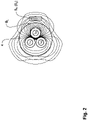
- the 2 shows a current sensor arrangement of the current sensors S1, S2 with the line section 4 to be monitored in a cross-sectional representation.
- the line section 4 to be monitored comprises three active conductors L1, L2, L3, which carry the load current IL ( 1 ) lead, which generates an alternating magnetic field BL in the detection range of the current sensors S1, S2.
- the two current sensors S1, S2 are arranged one behind the other along the longitudinal extension of the line section 4 and in the circumferential direction of the line section 4 both at the height of the conductor L3 - in this cross-sectional view, the second current sensor S2 is covered by the first current sensor S1 and is not visible. Simulations of the alternating magnetic field BL generated by the load current and the common-mode magnetic field Bp caused by the localization current have shown that it is advantageous to arrange the two current sensors S1, S2 circumferentially at the height of an active conductor L1, L2, L3 in order to to achieve good detection of the alternating magnetic field BL.
- the current sensors S1, S2 For effective detection of the common-mode magnetic field Bp caused by the localization current Ip, it is also expedient to use the current sensors S1, S2 to be arranged starting from the line section 4 in the direction of earth.
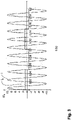
- FIG. 3 to 6 each show current and signal curves at different measuring points of the magnetic field measuring device 2.
- the size ratio of the localization current Ip to the mains-frequency load current IL is 1 to 10 instead of a ratio of 1 to be expected in reality been reduced to 1000.
- the sizes are given in standardized form.
- FIG. 3 shows the mains-frequency, sinusoidal load current IL in relation to the localization current Ip, which has a square-wave curve here.
- the frequency of the load current IL is 50 Hz (mains frequency)
- the fundamental frequency of the square wave of the localization current Ip is 10 Hz, which corresponds to a period Tp ( 7 ) of 0.1 s.
- other waveforms such as sinusoidal or triangular oscillations with possibly other frequencies can also be used, as long as they result in an analyzable localization signal xp after detection and signal processing.
- In 4 is the superposition of the in 3 illustrated load current IL with the in 3 shown localization current Ip shown.
- This current profile generates a magnetic field, consisting of the alternating magnetic field BL and the common-mode magnetic field Bp, which acts in the same way on the first current sensor S1 and on the second current sensor S2.
- figure 5 shows the course of the compensation current Ik, which feeds the compensation coil Ak to generate the compensation magnetic field Bk.
- the coarse quantization of the compensation current Ik as a result of the low magnetic field measurement sensitivity of the current sensor S2 can be seen. Quantization was used for better illustration performed here with 5 bits, corresponding to 32 quantization levels.
- the magnetic field measurement sensitivity of the first current sensor S1 should be so high that the magnetic field of the localization current Ip can be resolved to such a high level that reliable detection of the localization current Ip is possible.
- the magnetic field measuring range the largest possible dynamic range should be aimed for within the framework of economic considerations. A depiction of the dynamic range with 14 to 16 bits seems reasonable in terms of costs.
- the magnetic field measuring range of the second current sensor S2 should be large enough that the maximum strength of the alternating magnetic field BL caused by the mains-frequency load current IL can be processed without exceeding the measuring range.
- the dynamic range of the second current sensor S2 should be dimensioned in such a way that the magnetic field measurement sensitivity of the second current sensor S2 can be around 64 (corresponds to 6 bits) to 512 (corresponds to 9 bits) times lower than that of the first current sensor S1.
- a dynamic range that can be mapped with 12 bits is usually sufficient for the second current sensor S2.
- the overall dynamic range of the measured values recorded by the combination of the first and second current sensors S1, S2 reaches approximately 22 bits to 24 bits.
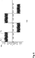
- FIG. 6 shows a sensor output signal xs1 of the first current sensor S1 after compensation compared to a sensor output signal xsi, which is caused by an impressed, undisturbed localization current Ip.
- the average level of a positive/negative (test) pulse of the sensor output signal xs1 after the compensation corresponds to an undisturbed sensor output signal xsi, so that the localization signal xp derived from the sensor output signal xs1 in the first signal processing block V1 is a simple and reliable detection of the localization current Ip.
- the measurement period Tm extends over two periods Tp of the localization current Ip.
- the lower line represents the effective value xs2eff of the second sensor output signal xs2, which changes abruptly during the measurement period Tm due to a change in the alternating magnetic field BL (load current change) - however, the change is only so large that the magnetic field measurement range of the first current sensor S1 is not exceeded.
- the AC voltage signal xs at the output of the second signal processing block V2 is continued unchanged during the measuring period Tm, its effective value xseff is therefore constant held.
- the change in the alternating magnetic field BL during the measurement period Tm i.e.
- the jump in the effective value xs2eff of the second sensor output signal xs2 is only noticeable in the effective value xseff at the beginning of the next measurement period Tm and, since there is no changed value at the beginning of this following measurement period Tm, used as effective value xseff for this following measurement period Tm.
- the measuring period Tm' is terminated and restarted with an adjusted effective value xseff.
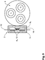
- FIG. 9 shows an implementation of the magnetic field measuring device 2 according to the invention in a schematic representation.
- the position of the magnetic field measuring device 2 in relation to the line section 4 to be checked is shown in a cross-sectional representation.
- the magnetic field measuring device 2 consists of a printed circuit board 10 on which the compensation coil Ak is applied as a planar coil with a winding designed as a conductor track 12 .
- Compensation current Ik flows through conductor track 12 and generates a compensation magnetic field Bk, which is guided in a planar core 14 made of ferrite.
- the first current sensor S1 for detecting the compensation magnetic field Bk, the alternating magnetic field BL and the common-mode magnetic field Bp is arranged in an air gap 16 of the planar core 14 .
- the second current sensor S2 which is preferably also arranged on the printed circuit board 10, but at such a distance from the first current sensor that the compensation magnetic field generated by the compensation coil Ak Bk does not affect the detection range of the second current sensor S2.
Landscapes
- Physics & Mathematics (AREA)
- General Physics & Mathematics (AREA)
- Engineering & Computer Science (AREA)
- Power Engineering (AREA)
- Condensed Matter Physics & Semiconductors (AREA)
- Electromagnetism (AREA)
- Measuring Instrument Details And Bridges, And Automatic Balancing Devices (AREA)
Claims (15)
- Dispositif de mesure (2) du champ magnétique pour détecter un courant de localisation (Ip) dans un système d'alimentation électrique en courant alternatif branché, un courant de charge (IL) ayant une fréquence industrielle écoulant dans une section de ligne (4) à être testée du système d'alimentation électrique en courant alternatif et le courant de localisation (Ip) ayant une fréquence fondamentale plus inférieure que la fréquence industrielle, le dispositif de mesure (2) du champ magnétique ayant un ensemble de capteurs de courant montable sur la section de ligne à être testée,
caractérisé en ce quel'ensemble de capteurs de courant consiste en un premier capteur de courant (S1), en un deuxième capteur de courant (S2) et en une bobine de compensation (Ak), qui génère un champ magnétique de compensation (Bk) agissant dans une plage de détection du premier capteur de courant (S1) et servant à compenser partiellement un champ magnétique alternatif (BL) à fréquence industrielle qui est effectué par le courant de charge (IL),et en ce que le dispositif de mesure (2) du champ magnétique a un premier bloc (V1) de traitement de signal, un deuxième bloc (V2) de traitement de signal et un bloc de compensation (Vk),le premier capteur de courant (S1) et le deuxième capteur de courant (S2) étant disposés de telle manière qu'en plus du champ magnétique de compensation (Bk), le premier capteur de courant (S1) détecte le champ magnétique alternatif (BL) et un champ magnétique (Bp) en mode commun effectué par le courant de localisation (Ip) comme champ magnétique (B1) compensé partiellement et l'impact du champ magnétique de compensation (Bk), qui est généré par la bobine de compensation (Ak), sur le deuxième capteur de courant (S2) est négligeable, le deuxième capteur de courant (S2) donc détectant seulement le champ magnétique alternatif (BL) et le champ magnétique (Bp) en mode commun effectué par le courant de localisation (Ip) comme champ magnétique (B2) résultant,le premier bloc (V1) de traitement de signal générant un signal de localisation (xp) indiquant le courant de localisation (Ip) d'un premier signal (xs1) de sortie de capteur généré par le premier capteur de courant (S1),le deuxième bloc (V2) de traitement de signal générant un signal de tension alternative (xs) correspondant au champ magnétique (B2) résultant d'un deuxième signal (xs2) de sortie de capteur généré par le deuxième capteur de courant (S2) etle bloc de compensation (Vk) relié en en aval du deuxième bloc (V2) de traitement de signal générant un courant de compensation (Ik), qui alimente la bobine de compensation (Ak) en énergie, du signal de tension alternative (xs) etle deuxième bloc (V2) de traitement de signal ayant une entrée de signal pour recevoir un signal de synchronisation (xsync) afin de synchroniser une période de mesure (Tm) spécifiée, pendant laquelle le courant de localisation (Ip) est détecté, avec le signal de tension alternative (xs), etles capteurs de courant (S1, S2) étant conçus de telle manière que, en comparaison au premier capteur de courant (S1), le deuxième capteur de courant (S2) a une sensibilité de mesure du champ magnétique plus inférieure et a une plage de mesure du champ magnétique plus grande, pour cette raison la compensation partielle a lieu seulement dans la mesure que le champ magnétique (B1) compensé partiellement n'excède pas la plage de mesure du champ magnétique du premier capteur de courant (S1). - Dispositif de mesure du champ magnétique selon la revendication 1, caractérisé en ce que
le deuxième bloc (V2) de traitement de signal est conçu de telle manière que le signal de tension alternative (xs) généré est continué de manière inchangée pendant la période de mesure (Tm), la période de mesure (Tm) étendant sur plusieurs périodes (Tp) du courant de localisation (Ip). - Dispositif de mesure du champ magnétique selon la revendication 1 ou la revendication 2,
caractérisé en ce que
le deuxième bloc (V2) de traitement de signal a une détection de surcharge (11) pour générer un signal de surcharge (xov) en cas d'une surcharge de la plage de mesure du champ magnétique du premier capteur de courant (S1). - Dispositif de mesure du champ magnétique selon l'une quelconque des revendications 1 à 3,
caractérisé en ce que
le bloc de compensation (Vk) a un circuit d'ajustement (12) pour ajuster le courant de compensation (Ik) et une entrée de signal pour recevoir un signal d'ajustement (xad) généré par le deuxième bloc (V2) de traitement de signal. - Dispositif de mesure du champ magnétique selon l'une quelconque des revendications 1 à 4,
caractérisé en ce que
le premier bloc (V1) de traitement de signal est conçu pour générer un signal de compensation fine (xf) qui est alimenté au bloc de compensation (Vk) pour une compensation fine du champ magnétique alternatif (BL). - Dispositif de mesure du champ magnétique selon l'une quelconque des revendications 1 à 5,
caractérisé en ce que
la bobine de compensation (Ak) est une bobine plane dont enroulement est réalisé comme pas de conduction sur un circuit imprimé (10) et qui a un noyau plan (14) en ferrite. - Dispositif de mesure du champ magnétique selon la revendication 6, caractérisé en ce que
le noyau plan (14) a concentriquement un entrefer (16) dans lequel le premier capteur de courant (S1) est disposé. - Dispositif de mesure du champ magnétique selon l'une quelconque des revendications 6 ou la revendication 7,
caractérisé par
une réalisation comme ensemble de construction indépendant consistant du circuit imprimé (10) et un boîtier encerclant ou une masse de scellement, des composants électroniques pour le traitement de signal étant disposés de plus sur le circuit imprimé (10). - Dispositif de mesure du champ magnétique selon l'une quelconque des revendications 6 à 8,
caractérisé en ce que
le deuxième capteur de courant (S2) est disposé sur le circuit imprimé (10) ou est réalisé comme unité structurelle séparée. - Utilisation d'un dispositif de mesure du champ magnétique selon l'une quelconque des revendications 3 à 9,
comme dispositif pour détecter un courant de localisation pour un système (IFLS) de localisation de défaut d'isolement dans un système d'alimentation électrique en courant alternatif, le signal de localisation (xp) étant transmis vers une unité d'évaluation (15) du système (IFLS) de localisation de défaut d'isolement, le signal de synchronisation (xsync) étant émis par le système (IFLS) de localisation de défaut d'isolement et le signal de surcharge (xov) étant alimenté au système (IFLS) de localisation de défaut d'isolement. - Procédé pour détecter un courant de localisation (Ip) dans un système d'alimentation électrique en courant alternatif branché, un courant de charge (IL) ayant une fréquence industrielle écoulant dans une section de ligne (4) à être testée du système d'alimentation électrique en courant alternatif et le courant de localisation (Ip) ayant une fréquence fondamentale plus inférieure que la fréquence industrielle, le procédé comprenant les étapes suivantes :monter un ensemble de capteurs de courant consistant en un premier capteur de courant (S1), en un deuxième capteur de courant (S2) et en une bobine de compensation (Ak), qui génère un champ magnétique de compensation (Bk) agissant dans une plage de détection du premier capteur de courant (S1) et servant à compenser partiellement un champ magnétique alternatif (BL) à fréquence industrielle qui est effectué par le courant de charge (IL), sur la section de ligne à être testée de telle manière quele premier capteur de courant (S1) et le deuxième capteur de courant (S2) sont disposés de telle manière qu'en plus du champ magnétique de compensation (Bk), le premier capteur de courant (S1) détecte le champ magnétique alternatif (BL) et un champ magnétique (Bp) en mode commun effectué par le courant de localisation (Ip) comme champ magnétique (B1) compensé partiellement et l'impact du champ magnétique de compensation (Bk) généré par la bobine de compensation (Ak) sur le deuxième capteur de courant (S2) est négligeable, le deuxième capteur de courant (S2) donc détectant seulement le champ magnétique alternatif (BL) et le champ magnétique (Bp) en mode commun effectué par le courant de localisation (Ip) comme champ magnétique (B2) résultant,générer un signal de localisation (xp) indiquant le courant de localisation (Ip) d'un premier signal (xs1) de sortie de capteur, qui est généré par le premier capteur de courant (S1), au moyen d'un premier bloc (V1) de traitement de signal,générer un signal de tension alternative (xs) d'un deuxième signal (xs2) de sortie de capteur, qui est généré par le deuxième capteur de courant (S2), au moyen d'un deuxième bloc (V2) de traitement de signal,générer un courant de compensation (Ik), qui alimente la bobine de compensation (Ak) en énergie, du signal de tension alternative (xs), qui est généré par le deuxième bloc (V2) de traitement de signal, au moyen d'un bloc de compensation (Vk),recevoir un signal de synchronisation (xsync) dans le deuxième bloc (V2) de traitement de signal afin de synchroniser une période de mesure (Tm) spécifiée, pendant laquelle le courant de localisation (Ip) est détecté, avec le signal de tension alternative (xs), etles capteurs de courant (S1, S2) étant choisis de telle manière que, en comparaison au premier capteur de courant (S1), le deuxième capteur de courant (S2) a une sensibilité de mesure du champ magnétique plus inférieure et une plage de mesure du champ magnétique plus supérieure, pour telle raison la compensation partielle a lieu seulement dans la mesure que le champ magnétique (B1) compensé partiellement n'excède pas la plage de mesure du champ magnétique du premier capteur de courant (S1).
- Procédé selon la revendication 11,
caractérisé en ce que
le signal de tension alternative (xs) généré est continu de manière inchangée pendant la période de mesure (Tm), la période de mesure (Tm) étendant sur plusieurs périodes (Tp) du courant de localisation (Ip). - Procédé selon la revendication 11 ou la revendication 12, caractérisé par
générer un signal de surcharge (xov) pour détecter une surcharge de la plage de mesure du champ magnétique du premier capteur de courant (S1) dans le deuxième bloc (V2) de traitement de signal. - Procédé selon la revendication 13,
caractérisé par
ajuster le courant de compensation (Ik) dans le bloc de compensation (Vk) en cas que le bloc de compensation (Vk) reçoit un signal d'ajustement (xad) du deuxième bloc (V2) de traitement de signal. - Procédé selon l'une quelconque des revendications 11 à 14, caractérisé par
générer un signal de compensation fine (xf) dans le premier bloc (V1) de traitement de signal, qui est alimenté au bloc de compensation (Vk) pour la compensation fine du champ magnétique alternatif (BL).
Applications Claiming Priority (1)
| Application Number | Priority Date | Filing Date | Title |
|---|---|---|---|
| DE102018130690.3A DE102018130690B3 (de) | 2018-12-03 | 2018-12-03 | Magnetfeld-Messvorrichtung und Verfahren zur Erfassung eines Lokalisierungsstroms in einem verzweigten Wechselstrom-Stromversorgungssystem |
Publications (2)
| Publication Number | Publication Date |
|---|---|
| EP3663783A1 EP3663783A1 (fr) | 2020-06-10 |
| EP3663783B1 true EP3663783B1 (fr) | 2023-01-04 |
Family
ID=68732636
Family Applications (1)
| Application Number | Title | Priority Date | Filing Date |
|---|---|---|---|
| EP19209892.9A Active EP3663783B1 (fr) | 2018-12-03 | 2019-11-19 | Dispositif de mesure de champ magnétique et procédé de détection d'un courant de localisation dans un système ramifié d'alimentation électrique à courant alternatif |
Country Status (4)
| Country | Link |
|---|---|
| US (1) | US11169198B2 (fr) |
| EP (1) | EP3663783B1 (fr) |
| CN (2) | CN111257652B (fr) |
| DE (1) | DE102018130690B3 (fr) |
Families Citing this family (8)
| Publication number | Priority date | Publication date | Assignee | Title |
|---|---|---|---|---|
| DE102018130690B3 (de) * | 2018-12-03 | 2020-03-26 | Bender Gmbh & Co. Kg | Magnetfeld-Messvorrichtung und Verfahren zur Erfassung eines Lokalisierungsstroms in einem verzweigten Wechselstrom-Stromversorgungssystem |
| CN112505475B (zh) * | 2020-11-10 | 2023-09-12 | 广西电网有限责任公司河池供电局 | 低成本非接触式的架空输电线路故障区间定位方法及系统 |
| CN112486035A (zh) * | 2020-11-18 | 2021-03-12 | 上海电力大学 | 一种用于变压器早期故障研究的软硬件仿真系统 |
| CN115902345B (zh) * | 2022-10-18 | 2024-07-02 | 苏州纳芯微电子股份有限公司 | 电流检测模块、用电设备及电流检测方法 |
| CN116704691A (zh) * | 2022-11-21 | 2023-09-05 | 敦煌研究院 | 一种改进式新型剩余电流的报警方法 |
| CN116500499B (zh) * | 2023-06-26 | 2023-09-15 | 陕西雨唐连创科技有限公司 | 一种三芯电缆故障检测装置、系统和方法 |
| CN117706258B (zh) * | 2024-02-06 | 2024-05-10 | 广州尚航信息科技股份有限公司 | 一种基于大数据处理的故障检测系统 |
| JP7536374B1 (ja) | 2024-03-19 | 2024-08-20 | イージー コリア | 電力線装着型電流センサー |
Family Cites Families (25)
| Publication number | Priority date | Publication date | Assignee | Title |
|---|---|---|---|---|
| US4278940A (en) * | 1979-04-25 | 1981-07-14 | General Electric Company | Means for automatically compensating DC magnetization in a transformer |
| FR2645650B1 (fr) * | 1989-04-06 | 1991-09-27 | Merlin Gerin | Systeme de controle d'isolement d'un reseau a courant continu |
| US6984978B2 (en) * | 2002-02-11 | 2006-01-10 | Honeywell International Inc. | Magnetic field sensor |
| ES2197020B1 (es) * | 2002-06-12 | 2005-03-01 | Diseño De Sistemas En Silicio, S.A. | Procedimiento y dispositivo de compensacion de campo magnetico de baja frecuencia en una unidad de acoplamiento de señal inductiva. |
| US7164263B2 (en) * | 2004-01-16 | 2007-01-16 | Fieldmetrics, Inc. | Current sensor |
| US7288928B2 (en) * | 2005-06-27 | 2007-10-30 | Greenwich Instruments Co., Inc. | Solenoidal Hall effects current sensor |
| WO2007138508A1 (fr) * | 2006-05-30 | 2007-12-06 | Koninklijke Philips Electronics N. V. | Dispositif de détection à compensation de champ adaptative |
| DE602008004301D1 (de) * | 2008-01-25 | 2011-02-17 | Lem Liaisons Electron Mec | Stromsensor |
| DE102011002756A1 (de) * | 2011-01-17 | 2012-07-19 | Sunways Ag Photovoltaic Technology | Strommessvorrichtung zum Erfassen eines Stroms, Solarinverter und Verfahren zum Erfassen eines Stroms |
| ES2535750T3 (es) * | 2012-12-06 | 2015-05-14 | Schneider Electric Industries Sas | Detección direccional de un defecto, particularmente en una red de neutro compensado o aislado |
| CN203012073U (zh) * | 2012-12-31 | 2013-06-19 | 广东电网公司电力科学研究院 | 配电网线路故障定位系统 |
| US9389281B2 (en) * | 2013-03-21 | 2016-07-12 | Vale S.A. | Magnetic compensation circuit and method for compensating the output of a magnetic sensor, responding to changes in a first magnetic field |
| CN104076243B (zh) * | 2013-03-29 | 2016-11-09 | 北京映翰通网络技术股份有限公司 | 一种小电流接地配电网单相接地故障检测指示方法与设备 |
| WO2014154164A1 (fr) * | 2013-03-29 | 2014-10-02 | 北京映翰通网络技术股份有限公司 | Procédé et système de détection et de localisation d'un défaut de masse monophasé sur un réseau de distribution d'énergie mis à la masse à faible courant |
| US9704637B2 (en) * | 2013-07-15 | 2017-07-11 | Texas Instruments Incorporated | Method and apparatus for demagnetizing transformer cores in closed loop magnetic current sensors |
| US9291648B2 (en) * | 2013-08-07 | 2016-03-22 | Texas Instruments Incorporated | Hybrid closed-loop/open-loop magnetic current sensor |
| DE102013218836A1 (de) * | 2013-09-19 | 2015-03-19 | Bender Gmbh & Co. Kg | Isolationsfehlersuchsystem mit zweigselektiver Einspeisung und selektives Isolationsüberwachungssystem sowie Verfahren zur Bestimmung einer Querverbindungsimpedanz zwischen zwei Subsystemen |
| US9829512B2 (en) * | 2013-10-21 | 2017-11-28 | Guildline Instruments Limited | Methods and systems relating to AC current measurements |
| EP2905627B1 (fr) * | 2014-02-06 | 2016-10-26 | Roland Hinke | Dispositif et procédé de mesure précise sans contact de la part de courant continu dans un courant ondulatoire |
| DE102015214615A1 (de) * | 2015-07-31 | 2017-02-02 | Bender Gmbh & Co. Kg | Verfahren und Vorrichtungen zur erweiterten Isolationsfehlersuche mit multifunktionalem Prüfstrom |
| DE102016211981A1 (de) * | 2016-06-30 | 2018-01-04 | Robert Bosch Gmbh | Spulenanordnung und zugehörige Messanordnung |
| FR3060757B1 (fr) * | 2016-12-19 | 2020-11-06 | Safran Electronics & Defense | Capteur de courant a vanne de flux |
| DE102017205931B3 (de) * | 2017-04-06 | 2018-07-26 | Bender Gmbh & Co. Kg | Isolationsfehlersuchsysteme und Verfahren zur Isolationsfehlersuche für ein redundantes Dioden gekoppeltes Gleichstrom-Stromversorgungssystem |
| CN108169538A (zh) * | 2018-03-19 | 2018-06-15 | 深圳市航智精密电子有限公司 | 磁通门电流传感器的多闭环控制电路 |
| DE102018130690B3 (de) * | 2018-12-03 | 2020-03-26 | Bender Gmbh & Co. Kg | Magnetfeld-Messvorrichtung und Verfahren zur Erfassung eines Lokalisierungsstroms in einem verzweigten Wechselstrom-Stromversorgungssystem |
-
2018
- 2018-12-03 DE DE102018130690.3A patent/DE102018130690B3/de not_active Expired - Fee Related
-
2019
- 2019-11-19 EP EP19209892.9A patent/EP3663783B1/fr active Active
- 2019-12-02 US US16/699,787 patent/US11169198B2/en active Active
- 2019-12-03 CN CN201911218860.1A patent/CN111257652B/zh active Active
- 2019-12-03 CN CN201922132543.XU patent/CN212459864U/zh not_active Withdrawn - After Issue
Also Published As
| Publication number | Publication date |
|---|---|
| CN111257652B (zh) | 2023-01-10 |
| US20200174059A1 (en) | 2020-06-04 |
| CN111257652A (zh) | 2020-06-09 |
| CN212459864U (zh) | 2021-02-02 |
| US11169198B2 (en) | 2021-11-09 |
| EP3663783A1 (fr) | 2020-06-10 |
| DE102018130690B3 (de) | 2020-03-26 |
Similar Documents
| Publication | Publication Date | Title |
|---|---|---|
| DE102018130690B3 (de) | Magnetfeld-Messvorrichtung und Verfahren zur Erfassung eines Lokalisierungsstroms in einem verzweigten Wechselstrom-Stromversorgungssystem | |
| EP1166131A1 (fr) | Mesureur de courant | |
| EP3385733B1 (fr) | Systèmes de détection d'erreurs d'isolation et procédés de détection d'erreurs d'isolation pour un système d'alimentation en courant continu redondant couplé aux diodes | |
| EP2558875A1 (fr) | Procédé et dispositif pour la détection d'une grandeur magnétique caractéristique dans un noyau | |
| WO2012098054A1 (fr) | Dispositif de mesure de courant | |
| DE112005001167B4 (de) | Differenzstromdetektion | |
| DE102018210466A1 (de) | Stromstärkeerfassungsgerät und Messgerät | |
| EP1972947A2 (fr) | Dispositif destiné à mesurer une composante DC superposée à une composante AC d'un courant circulant dans des conducteurs de chemin de fer à courant alternatif | |
| DE69329326T2 (de) | Verfahren und Vorrichtung zum Messen der Anpassung und Fehlanpassung der Kompensation eines Stromversorgungsnetzes | |
| DE102021131702B4 (de) | Verfahren und Einrichtung zur Isolationsüberwachung und Isolationsfehlersuche für ungeerdete Stromversorgungsnetze | |
| DE102019132071B4 (de) | Vorrichtung zum Überwachen eines Versorgungsnetzes | |
| DE69213521T2 (de) | Verfahren und Anordnung zur Erkennung einer Sättigung von Stromwandlertransformatoren | |
| EP3269015A1 (fr) | Procédé de détermination d'état et de localisation de défauts sur des dérivations isolées installées dans un système de protection extérieure contre la foudre | |
| WO2020052942A1 (fr) | Dispositif de détermination d'un courant total dans une ligne | |
| EP4045922B1 (fr) | Procédé et dispositif pour déterminer la composante résistive de l'impédance de courant de fuite dans un réseau à courant alternatif | |
| EP1927005A1 (fr) | Dispositif permettant de determiner l'intensite du champ magnetique d'un electroaimant | |
| WO2008145694A1 (fr) | Procédé de correction d'un trajet de courant secondaire perturbe par la saturation d'un transformateur de courant et dispositif de champ électrique pour la réalisation d'un tel procédé | |
| DE4135425C2 (de) | Vorrichtung zum Feststellen und Anzeigen eines Fehlers in elektrischen Leitungen | |
| DE69308446T2 (de) | Einrichtung zum Feststellen von Fehlern auf einem unterirdischen elektrischen Energieverteilungsnetz | |
| EP0927356B2 (fr) | Procede de verification de composants electriques et dispositif permettant de mettre ledit procede en oeuvre | |
| EP4369008B1 (fr) | Procédé et agencement de circuit électrique pour déterminer sélectivement par branche des variables résistives et capacitives d'isolation dans un système d'alimentation électrique ramifié et sans mise à la terre | |
| DE102005054544B4 (de) | Verfahren und Einrichtung zur Ortung von Isolationsfehlern in isolierten ungeerdeten Wechselspannungsnetzen | |
| EP2057726A1 (fr) | Procédé et système de protection différentielle | |
| DE102019133121A1 (de) | Feldgerät sowie Verfahren zum Betreiben eines Feldgerätes | |
| DE102004007369A1 (de) | Schaltungsanordnung sowie Verfahren zur Detektion eines Masseschlusses |
Legal Events
| Date | Code | Title | Description |
|---|---|---|---|
| PUAI | Public reference made under article 153(3) epc to a published international application that has entered the european phase |
Free format text: ORIGINAL CODE: 0009012 |
|
| STAA | Information on the status of an ep patent application or granted ep patent |
Free format text: STATUS: THE APPLICATION HAS BEEN PUBLISHED |
|
| AK | Designated contracting states |
Kind code of ref document: A1 Designated state(s): AL AT BE BG CH CY CZ DE DK EE ES FI FR GB GR HR HU IE IS IT LI LT LU LV MC MK MT NL NO PL PT RO RS SE SI SK SM TR |
|
| AX | Request for extension of the european patent |
Extension state: BA ME |
|
| STAA | Information on the status of an ep patent application or granted ep patent |
Free format text: STATUS: REQUEST FOR EXAMINATION WAS MADE |
|
| 17P | Request for examination filed |
Effective date: 20201021 |
|
| RBV | Designated contracting states (corrected) |
Designated state(s): AL AT BE BG CH CY CZ DE DK EE ES FI FR GB GR HR HU IE IS IT LI LT LU LV MC MK MT NL NO PL PT RO RS SE SI SK SM TR |
|
| GRAP | Despatch of communication of intention to grant a patent |
Free format text: ORIGINAL CODE: EPIDOSNIGR1 |
|
| STAA | Information on the status of an ep patent application or granted ep patent |
Free format text: STATUS: GRANT OF PATENT IS INTENDED |
|
| RIC1 | Information provided on ipc code assigned before grant |
Ipc: G01R 31/08 20200101ALI20220324BHEP Ipc: G01R 15/18 20060101ALI20220324BHEP Ipc: G01R 15/20 20060101ALI20220324BHEP Ipc: G01R 31/52 20200101AFI20220324BHEP |
|
| INTG | Intention to grant announced |
Effective date: 20220419 |
|
| GRAJ | Information related to disapproval of communication of intention to grant by the applicant or resumption of examination proceedings by the epo deleted |
Free format text: ORIGINAL CODE: EPIDOSDIGR1 |
|
| STAA | Information on the status of an ep patent application or granted ep patent |
Free format text: STATUS: REQUEST FOR EXAMINATION WAS MADE |
|
| GRAP | Despatch of communication of intention to grant a patent |
Free format text: ORIGINAL CODE: EPIDOSNIGR1 |
|
| STAA | Information on the status of an ep patent application or granted ep patent |
Free format text: STATUS: GRANT OF PATENT IS INTENDED |
|
| INTC | Intention to grant announced (deleted) | ||
| INTG | Intention to grant announced |
Effective date: 20220804 |
|
| GRAS | Grant fee paid |
Free format text: ORIGINAL CODE: EPIDOSNIGR3 |
|
| GRAA | (expected) grant |
Free format text: ORIGINAL CODE: 0009210 |
|
| STAA | Information on the status of an ep patent application or granted ep patent |
Free format text: STATUS: THE PATENT HAS BEEN GRANTED |
|
| AK | Designated contracting states |
Kind code of ref document: B1 Designated state(s): AL AT BE BG CH CY CZ DE DK EE ES FI FR GB GR HR HU IE IS IT LI LT LU LV MC MK MT NL NO PL PT RO RS SE SI SK SM TR |
|
| REG | Reference to a national code |
Ref country code: GB Ref legal event code: FG4D Free format text: NOT ENGLISH |
|
| REG | Reference to a national code |
Ref country code: CH Ref legal event code: EP |
|
| REG | Reference to a national code |
Ref country code: AT Ref legal event code: REF Ref document number: 1542320 Country of ref document: AT Kind code of ref document: T Effective date: 20230115 |
|
| REG | Reference to a national code |
Ref country code: DE Ref legal event code: R096 Ref document number: 502019006686 Country of ref document: DE |
|
| REG | Reference to a national code |
Ref country code: IE Ref legal event code: FG4D Free format text: LANGUAGE OF EP DOCUMENT: GERMAN |
|
| REG | Reference to a national code |
Ref country code: LT Ref legal event code: MG9D |
|
| REG | Reference to a national code |
Ref country code: NL Ref legal event code: MP Effective date: 20230104 |
|
| PG25 | Lapsed in a contracting state [announced via postgrant information from national office to epo] |
Ref country code: NL Free format text: LAPSE BECAUSE OF FAILURE TO SUBMIT A TRANSLATION OF THE DESCRIPTION OR TO PAY THE FEE WITHIN THE PRESCRIBED TIME-LIMIT Effective date: 20230104 |
|
| P01 | Opt-out of the competence of the unified patent court (upc) registered |
Effective date: 20230525 |
|
| PG25 | Lapsed in a contracting state [announced via postgrant information from national office to epo] |
Ref country code: RS Free format text: LAPSE BECAUSE OF FAILURE TO SUBMIT A TRANSLATION OF THE DESCRIPTION OR TO PAY THE FEE WITHIN THE PRESCRIBED TIME-LIMIT Effective date: 20230104 Ref country code: PT Free format text: LAPSE BECAUSE OF FAILURE TO SUBMIT A TRANSLATION OF THE DESCRIPTION OR TO PAY THE FEE WITHIN THE PRESCRIBED TIME-LIMIT Effective date: 20230504 Ref country code: NO Free format text: LAPSE BECAUSE OF FAILURE TO SUBMIT A TRANSLATION OF THE DESCRIPTION OR TO PAY THE FEE WITHIN THE PRESCRIBED TIME-LIMIT Effective date: 20230404 Ref country code: LV Free format text: LAPSE BECAUSE OF FAILURE TO SUBMIT A TRANSLATION OF THE DESCRIPTION OR TO PAY THE FEE WITHIN THE PRESCRIBED TIME-LIMIT Effective date: 20230104 Ref country code: LT Free format text: LAPSE BECAUSE OF FAILURE TO SUBMIT A TRANSLATION OF THE DESCRIPTION OR TO PAY THE FEE WITHIN THE PRESCRIBED TIME-LIMIT Effective date: 20230104 Ref country code: HR Free format text: LAPSE BECAUSE OF FAILURE TO SUBMIT A TRANSLATION OF THE DESCRIPTION OR TO PAY THE FEE WITHIN THE PRESCRIBED TIME-LIMIT Effective date: 20230104 Ref country code: ES Free format text: LAPSE BECAUSE OF FAILURE TO SUBMIT A TRANSLATION OF THE DESCRIPTION OR TO PAY THE FEE WITHIN THE PRESCRIBED TIME-LIMIT Effective date: 20230104 |
|
| PG25 | Lapsed in a contracting state [announced via postgrant information from national office to epo] |
Ref country code: SE Free format text: LAPSE BECAUSE OF FAILURE TO SUBMIT A TRANSLATION OF THE DESCRIPTION OR TO PAY THE FEE WITHIN THE PRESCRIBED TIME-LIMIT Effective date: 20230104 Ref country code: PL Free format text: LAPSE BECAUSE OF FAILURE TO SUBMIT A TRANSLATION OF THE DESCRIPTION OR TO PAY THE FEE WITHIN THE PRESCRIBED TIME-LIMIT Effective date: 20230104 Ref country code: IS Free format text: LAPSE BECAUSE OF FAILURE TO SUBMIT A TRANSLATION OF THE DESCRIPTION OR TO PAY THE FEE WITHIN THE PRESCRIBED TIME-LIMIT Effective date: 20230504 Ref country code: GR Free format text: LAPSE BECAUSE OF FAILURE TO SUBMIT A TRANSLATION OF THE DESCRIPTION OR TO PAY THE FEE WITHIN THE PRESCRIBED TIME-LIMIT Effective date: 20230405 Ref country code: FI Free format text: LAPSE BECAUSE OF FAILURE TO SUBMIT A TRANSLATION OF THE DESCRIPTION OR TO PAY THE FEE WITHIN THE PRESCRIBED TIME-LIMIT Effective date: 20230104 |
|
| REG | Reference to a national code |
Ref country code: DE Ref legal event code: R097 Ref document number: 502019006686 Country of ref document: DE |
|
| PG25 | Lapsed in a contracting state [announced via postgrant information from national office to epo] |
Ref country code: SM Free format text: LAPSE BECAUSE OF FAILURE TO SUBMIT A TRANSLATION OF THE DESCRIPTION OR TO PAY THE FEE WITHIN THE PRESCRIBED TIME-LIMIT Effective date: 20230104 Ref country code: RO Free format text: LAPSE BECAUSE OF FAILURE TO SUBMIT A TRANSLATION OF THE DESCRIPTION OR TO PAY THE FEE WITHIN THE PRESCRIBED TIME-LIMIT Effective date: 20230104 Ref country code: EE Free format text: LAPSE BECAUSE OF FAILURE TO SUBMIT A TRANSLATION OF THE DESCRIPTION OR TO PAY THE FEE WITHIN THE PRESCRIBED TIME-LIMIT Effective date: 20230104 Ref country code: DK Free format text: LAPSE BECAUSE OF FAILURE TO SUBMIT A TRANSLATION OF THE DESCRIPTION OR TO PAY THE FEE WITHIN THE PRESCRIBED TIME-LIMIT Effective date: 20230104 Ref country code: CZ Free format text: LAPSE BECAUSE OF FAILURE TO SUBMIT A TRANSLATION OF THE DESCRIPTION OR TO PAY THE FEE WITHIN THE PRESCRIBED TIME-LIMIT Effective date: 20230104 |
|
| PLBE | No opposition filed within time limit |
Free format text: ORIGINAL CODE: 0009261 |
|
| STAA | Information on the status of an ep patent application or granted ep patent |
Free format text: STATUS: NO OPPOSITION FILED WITHIN TIME LIMIT |
|
| PG25 | Lapsed in a contracting state [announced via postgrant information from national office to epo] |
Ref country code: SK Free format text: LAPSE BECAUSE OF FAILURE TO SUBMIT A TRANSLATION OF THE DESCRIPTION OR TO PAY THE FEE WITHIN THE PRESCRIBED TIME-LIMIT Effective date: 20230104 |
|
| 26N | No opposition filed |
Effective date: 20231005 |
|
| PG25 | Lapsed in a contracting state [announced via postgrant information from national office to epo] |
Ref country code: SI Free format text: LAPSE BECAUSE OF FAILURE TO SUBMIT A TRANSLATION OF THE DESCRIPTION OR TO PAY THE FEE WITHIN THE PRESCRIBED TIME-LIMIT Effective date: 20230104 |
|
| PG25 | Lapsed in a contracting state [announced via postgrant information from national office to epo] |
Ref country code: IT Free format text: LAPSE BECAUSE OF FAILURE TO SUBMIT A TRANSLATION OF THE DESCRIPTION OR TO PAY THE FEE WITHIN THE PRESCRIBED TIME-LIMIT Effective date: 20230104 |
|
| REG | Reference to a national code |
Ref country code: CH Ref legal event code: PL |
|
| PG25 | Lapsed in a contracting state [announced via postgrant information from national office to epo] |
Ref country code: MC Free format text: LAPSE BECAUSE OF FAILURE TO SUBMIT A TRANSLATION OF THE DESCRIPTION OR TO PAY THE FEE WITHIN THE PRESCRIBED TIME-LIMIT Effective date: 20230104 |
|
| PG25 | Lapsed in a contracting state [announced via postgrant information from national office to epo] |
Ref country code: LU Free format text: LAPSE BECAUSE OF NON-PAYMENT OF DUE FEES Effective date: 20231119 |
|
| PG25 | Lapsed in a contracting state [announced via postgrant information from national office to epo] |
Ref country code: CH Free format text: LAPSE BECAUSE OF NON-PAYMENT OF DUE FEES Effective date: 20231130 |
|
| PG25 | Lapsed in a contracting state [announced via postgrant information from national office to epo] |
Ref country code: MC Free format text: LAPSE BECAUSE OF FAILURE TO SUBMIT A TRANSLATION OF THE DESCRIPTION OR TO PAY THE FEE WITHIN THE PRESCRIBED TIME-LIMIT Effective date: 20230104 Ref country code: LU Free format text: LAPSE BECAUSE OF NON-PAYMENT OF DUE FEES Effective date: 20231119 Ref country code: CH Free format text: LAPSE BECAUSE OF NON-PAYMENT OF DUE FEES Effective date: 20231130 |
|
| REG | Reference to a national code |
Ref country code: BE Ref legal event code: MM Effective date: 20231130 |
|
| REG | Reference to a national code |
Ref country code: IE Ref legal event code: MM4A |
|
| PG25 | Lapsed in a contracting state [announced via postgrant information from national office to epo] |
Ref country code: IE Free format text: LAPSE BECAUSE OF NON-PAYMENT OF DUE FEES Effective date: 20231119 |
|
| PG25 | Lapsed in a contracting state [announced via postgrant information from national office to epo] |
Ref country code: BE Free format text: LAPSE BECAUSE OF NON-PAYMENT OF DUE FEES Effective date: 20231130 |
|
| PG25 | Lapsed in a contracting state [announced via postgrant information from national office to epo] |
Ref country code: IE Free format text: LAPSE BECAUSE OF NON-PAYMENT OF DUE FEES Effective date: 20231119 Ref country code: BE Free format text: LAPSE BECAUSE OF NON-PAYMENT OF DUE FEES Effective date: 20231130 |
|
| PG25 | Lapsed in a contracting state [announced via postgrant information from national office to epo] |
Ref country code: BG Free format text: LAPSE BECAUSE OF FAILURE TO SUBMIT A TRANSLATION OF THE DESCRIPTION OR TO PAY THE FEE WITHIN THE PRESCRIBED TIME-LIMIT Effective date: 20230104 |
|
| PG25 | Lapsed in a contracting state [announced via postgrant information from national office to epo] |
Ref country code: BG Free format text: LAPSE BECAUSE OF FAILURE TO SUBMIT A TRANSLATION OF THE DESCRIPTION OR TO PAY THE FEE WITHIN THE PRESCRIBED TIME-LIMIT Effective date: 20230104 |
|
| PG25 | Lapsed in a contracting state [announced via postgrant information from national office to epo] |
Ref country code: CY Free format text: LAPSE BECAUSE OF FAILURE TO SUBMIT A TRANSLATION OF THE DESCRIPTION OR TO PAY THE FEE WITHIN THE PRESCRIBED TIME-LIMIT; INVALID AB INITIO Effective date: 20191119 |
|
| PG25 | Lapsed in a contracting state [announced via postgrant information from national office to epo] |
Ref country code: HU Free format text: LAPSE BECAUSE OF FAILURE TO SUBMIT A TRANSLATION OF THE DESCRIPTION OR TO PAY THE FEE WITHIN THE PRESCRIBED TIME-LIMIT; INVALID AB INITIO Effective date: 20191119 |
|
| PG25 | Lapsed in a contracting state [announced via postgrant information from national office to epo] |
Ref country code: TR Free format text: LAPSE BECAUSE OF FAILURE TO SUBMIT A TRANSLATION OF THE DESCRIPTION OR TO PAY THE FEE WITHIN THE PRESCRIBED TIME-LIMIT Effective date: 20230104 |
|
| PGFP | Annual fee paid to national office [announced via postgrant information from national office to epo] |
Ref country code: DE Payment date: 20251118 Year of fee payment: 7 |
|
| PGFP | Annual fee paid to national office [announced via postgrant information from national office to epo] |
Ref country code: GB Payment date: 20251120 Year of fee payment: 7 |
|
| PG25 | Lapsed in a contracting state [announced via postgrant information from national office to epo] |
Ref country code: AT Free format text: LAPSE BECAUSE OF NON-PAYMENT OF DUE FEES Effective date: 20241119 |
|
| PGFP | Annual fee paid to national office [announced via postgrant information from national office to epo] |
Ref country code: FR Payment date: 20251120 Year of fee payment: 7 |
|
| REG | Reference to a national code |
Ref country code: AT Ref legal event code: MM01 Ref document number: 1542320 Country of ref document: AT Kind code of ref document: T Effective date: 20241119 |
|
| PGFP | Annual fee paid to national office [announced via postgrant information from national office to epo] |
Ref country code: AT Payment date: 20260410 Year of fee payment: 5 |