EP3663791B1 - Procédé et dispositif d'amélioration d'informations de profondeur d'une image 3d et véhicule aérien sans pilote - Google Patents
Procédé et dispositif d'amélioration d'informations de profondeur d'une image 3d et véhicule aérien sans pilote Download PDFInfo
- Publication number
- EP3663791B1 EP3663791B1 EP18846940.7A EP18846940A EP3663791B1 EP 3663791 B1 EP3663791 B1 EP 3663791B1 EP 18846940 A EP18846940 A EP 18846940A EP 3663791 B1 EP3663791 B1 EP 3663791B1
- Authority
- EP
- European Patent Office
- Prior art keywords
- exposure
- image
- time
- effective pixel
- exposure time
- Prior art date
- Legal status (The legal status is an assumption and is not a legal conclusion. Google has not performed a legal analysis and makes no representation as to the accuracy of the status listed.)
- Active
Links
Images


Classifications
-
- G—PHYSICS
- G01—MEASURING; TESTING
- G01S—RADIO DIRECTION-FINDING; RADIO NAVIGATION; DETERMINING DISTANCE OR VELOCITY BY USE OF RADIO WAVES; LOCATING OR PRESENCE-DETECTING BY USE OF THE REFLECTION OR RERADIATION OF RADIO WAVES; ANALOGOUS ARRANGEMENTS USING OTHER WAVES
- G01S7/00—Details of systems according to groups G01S13/00, G01S15/00, G01S17/00
- G01S7/48—Details of systems according to groups G01S13/00, G01S15/00, G01S17/00 of systems according to group G01S17/00
- G01S7/497—Means for monitoring or calibrating
-
- G—PHYSICS
- G01—MEASURING; TESTING
- G01S—RADIO DIRECTION-FINDING; RADIO NAVIGATION; DETERMINING DISTANCE OR VELOCITY BY USE OF RADIO WAVES; LOCATING OR PRESENCE-DETECTING BY USE OF THE REFLECTION OR RERADIATION OF RADIO WAVES; ANALOGOUS ARRANGEMENTS USING OTHER WAVES
- G01S17/00—Systems using the reflection or reradiation of electromagnetic waves other than radio waves, e.g. lidar systems
- G01S17/88—Lidar systems specially adapted for specific applications
- G01S17/89—Lidar systems specially adapted for specific applications for mapping or imaging
-
- G—PHYSICS
- G01—MEASURING; TESTING
- G01S—RADIO DIRECTION-FINDING; RADIO NAVIGATION; DETERMINING DISTANCE OR VELOCITY BY USE OF RADIO WAVES; LOCATING OR PRESENCE-DETECTING BY USE OF THE REFLECTION OR RERADIATION OF RADIO WAVES; ANALOGOUS ARRANGEMENTS USING OTHER WAVES
- G01S17/00—Systems using the reflection or reradiation of electromagnetic waves other than radio waves, e.g. lidar systems
- G01S17/88—Lidar systems specially adapted for specific applications
- G01S17/93—Lidar systems specially adapted for specific applications for anti-collision purposes
- G01S17/933—Lidar systems specially adapted for specific applications for anti-collision purposes of aircraft or spacecraft
-
- G—PHYSICS
- G01—MEASURING; TESTING
- G01S—RADIO DIRECTION-FINDING; RADIO NAVIGATION; DETERMINING DISTANCE OR VELOCITY BY USE OF RADIO WAVES; LOCATING OR PRESENCE-DETECTING BY USE OF THE REFLECTION OR RERADIATION OF RADIO WAVES; ANALOGOUS ARRANGEMENTS USING OTHER WAVES
- G01S7/00—Details of systems according to groups G01S13/00, G01S15/00, G01S17/00
- G01S7/48—Details of systems according to groups G01S13/00, G01S15/00, G01S17/00 of systems according to group G01S17/00
- G01S7/483—Details of pulse systems
- G01S7/486—Receivers
- G01S7/4868—Controlling received signal intensity or exposure of sensor
-
- G—PHYSICS
- G01—MEASURING; TESTING
- G01S—RADIO DIRECTION-FINDING; RADIO NAVIGATION; DETERMINING DISTANCE OR VELOCITY BY USE OF RADIO WAVES; LOCATING OR PRESENCE-DETECTING BY USE OF THE REFLECTION OR RERADIATION OF RADIO WAVES; ANALOGOUS ARRANGEMENTS USING OTHER WAVES
- G01S7/00—Details of systems according to groups G01S13/00, G01S15/00, G01S17/00
- G01S7/48—Details of systems according to groups G01S13/00, G01S15/00, G01S17/00 of systems according to group G01S17/00
- G01S7/491—Details of non-pulse systems
- G01S7/4912—Receivers
- G01S7/4918—Controlling received signal intensity, gain or exposure of sensor
-
- G—PHYSICS
- G06—COMPUTING OR CALCULATING; COUNTING
- G06T—IMAGE DATA PROCESSING OR GENERATION, IN GENERAL
- G06T5/00—Image enhancement or restoration
- G06T5/50—Image enhancement or restoration using two or more images, e.g. averaging or subtraction
-
- G—PHYSICS
- G06—COMPUTING OR CALCULATING; COUNTING
- G06T—IMAGE DATA PROCESSING OR GENERATION, IN GENERAL
- G06T7/00—Image analysis
- G06T7/50—Depth or shape recovery
- G06T7/55—Depth or shape recovery from multiple images
- G06T7/593—Depth or shape recovery from multiple images from stereo images
-
- H—ELECTRICITY
- H04—ELECTRIC COMMUNICATION TECHNIQUE
- H04N—PICTORIAL COMMUNICATION, e.g. TELEVISION
- H04N23/00—Cameras or camera modules comprising electronic image sensors; Control thereof
- H04N23/70—Circuitry for compensating brightness variation in the scene
-
- H—ELECTRICITY
- H04—ELECTRIC COMMUNICATION TECHNIQUE
- H04N—PICTORIAL COMMUNICATION, e.g. TELEVISION
- H04N23/00—Cameras or camera modules comprising electronic image sensors; Control thereof
- H04N23/70—Circuitry for compensating brightness variation in the scene
- H04N23/73—Circuitry for compensating brightness variation in the scene by influencing the exposure time
-
- B—PERFORMING OPERATIONS; TRANSPORTING
- B64—AIRCRAFT; AVIATION; COSMONAUTICS
- B64U—UNMANNED AERIAL VEHICLES [UAV]; EQUIPMENT THEREFOR
- B64U2101/00—UAVs specially adapted for particular uses or applications
- B64U2101/30—UAVs specially adapted for particular uses or applications for imaging, photography or videography
-
- B—PERFORMING OPERATIONS; TRANSPORTING
- B64—AIRCRAFT; AVIATION; COSMONAUTICS
- B64U—UNMANNED AERIAL VEHICLES [UAV]; EQUIPMENT THEREFOR
- B64U30/00—Means for producing lift; Empennages; Arrangements thereof
- B64U30/20—Rotors; Rotor supports
-
- G—PHYSICS
- G01—MEASURING; TESTING
- G01S—RADIO DIRECTION-FINDING; RADIO NAVIGATION; DETERMINING DISTANCE OR VELOCITY BY USE OF RADIO WAVES; LOCATING OR PRESENCE-DETECTING BY USE OF THE REFLECTION OR RERADIATION OF RADIO WAVES; ANALOGOUS ARRANGEMENTS USING OTHER WAVES
- G01S17/00—Systems using the reflection or reradiation of electromagnetic waves other than radio waves, e.g. lidar systems
- G01S17/02—Systems using the reflection of electromagnetic waves other than radio waves
- G01S17/06—Systems determining position data of a target
- G01S17/08—Systems determining position data of a target for measuring distance only
- G01S17/10—Systems determining position data of a target for measuring distance only using transmission of interrupted, pulse-modulated waves
-
- G—PHYSICS
- G01—MEASURING; TESTING
- G01S—RADIO DIRECTION-FINDING; RADIO NAVIGATION; DETERMINING DISTANCE OR VELOCITY BY USE OF RADIO WAVES; LOCATING OR PRESENCE-DETECTING BY USE OF THE REFLECTION OR RERADIATION OF RADIO WAVES; ANALOGOUS ARRANGEMENTS USING OTHER WAVES
- G01S17/00—Systems using the reflection or reradiation of electromagnetic waves other than radio waves, e.g. lidar systems
- G01S17/02—Systems using the reflection of electromagnetic waves other than radio waves
- G01S17/06—Systems determining position data of a target
- G01S17/08—Systems determining position data of a target for measuring distance only
- G01S17/32—Systems determining position data of a target for measuring distance only using transmission of continuous waves, whether amplitude-, frequency-, or phase-modulated, or unmodulated
- G01S17/36—Systems determining position data of a target for measuring distance only using transmission of continuous waves, whether amplitude-, frequency-, or phase-modulated, or unmodulated with phase comparison between the received signal and the contemporaneously transmitted signal
-
- G—PHYSICS
- G06—COMPUTING OR CALCULATING; COUNTING
- G06T—IMAGE DATA PROCESSING OR GENERATION, IN GENERAL
- G06T2207/00—Indexing scheme for image analysis or image enhancement
- G06T2207/10—Image acquisition modality
- G06T2207/10016—Video; Image sequence
- G06T2207/10021—Stereoscopic video; Stereoscopic image sequence
-
- G—PHYSICS
- G06—COMPUTING OR CALCULATING; COUNTING
- G06T—IMAGE DATA PROCESSING OR GENERATION, IN GENERAL
- G06T2207/00—Indexing scheme for image analysis or image enhancement
- G06T2207/10—Image acquisition modality
- G06T2207/10028—Range image; Depth image; 3D point clouds
-
- G—PHYSICS
- G06—COMPUTING OR CALCULATING; COUNTING
- G06T—IMAGE DATA PROCESSING OR GENERATION, IN GENERAL
- G06T2207/00—Indexing scheme for image analysis or image enhancement
- G06T2207/10—Image acquisition modality
- G06T2207/10141—Special mode during image acquisition
- G06T2207/10144—Varying exposure
-
- G—PHYSICS
- G06—COMPUTING OR CALCULATING; COUNTING
- G06T—IMAGE DATA PROCESSING OR GENERATION, IN GENERAL
- G06T2207/00—Indexing scheme for image analysis or image enhancement
- G06T2207/30—Subject of image; Context of image processing
- G06T2207/30248—Vehicle exterior or interior
- G06T2207/30252—Vehicle exterior; Vicinity of vehicle
- G06T2207/30261—Obstacle
Definitions
- Implementations of the present invention relate to the technical field of unmanned aerial vehicles, and in particular, to a method and an apparatus for improving 3D image depth information and an unmanned aerial vehicle.
- an unmanned aerial vehicle adopts a 3D depth camera to photograph a 3D image, acquires information about a depth of field in the 3D image, and determines a position of an obstacle according to the depth of field for ranging and obstacle avoidance.
- UAV unmanned aerial vehicle
- TOF is an acronym of time of flight, and is translated into Fei Xing Shi Jian in Chinese.
- signal quality of a weakly reflective region may be improved to a certain extent, for a highly reflective region, saturation may occur and overexposure is produced.
- overexposure may cause erroneous determining or missing detection of the obstacle, causing collisions between the UAV and an obstacle.
- Document D1 discloses that in a distance measuring device, a drive controller (103) generates an emission timing signal (SG1) and an exposure timing signal (SG2) in accordance with a measurement condition.
- a light source (104) irradiates light in response to the emission timing signal (SG1).
- a solid-state image sensor (109) has a group of pixels arranged in a matrix pattern and divided into a plurality of regions on a line-by-line basis, and performs an exposure process on a selected one of the regions in response to the exposure timing signal (SG2).
- An imaging signal processor (101) obtains distance information by performing an arithmetic operation on a signal output from the solid-state image sensor (109).
- the drive controller (103) generates mutually different measurement conditions to the plurality of the regions of the solid-state image sensor (109).
- Document D2 discloses an enhanced distance detection system for an autonomous or semi-autonomous vehicle.
- the distance detection system includes a distance detector, which may have a limited scope of distance detection, and a directional controller, which allows extending the dimension or scope of the distance detector as the vehicle travels and performs missions.
- the directional controller can change the detection direction of the distance detector with a motorized gimbal or functionally similar system, and the change in the detection direction can be integrated with the status of and other instructions executed by the vehicle.
- Document D3 discloses a system, method, and computer program product for generating an image stack.
- one or more exposure parameters for an image stack are configured.
- a capture command is received.
- a pixel array is initialized within an image sensor of the camera module.
- one or more ambient images are sampled within one or more corresponding analog storage planes.
- a strobe unit is enabled, where, if it is determined that the strobe unit is enabled, one or more strobe images are sampled within the corresponding analog storage planes.
- implementations of the present invention provide a method and an apparatus for improving 3D image depth information and an unmanned aerial vehicle (UAV), so that a problem in the prior art that a poor exposure effect of a photo photographed by a 3D depth camera causes poor image quality can be resolved.
- UAV unmanned aerial vehicle
- a method for improving 3D image depth information is provided, where the method includes:
- the method further includes: presetting an exposure time gradient array, the gradient array including exposure times with several time lengths arranged in ascending order, where an exposure time with the maximum time length is an exposure time threshold.
- the acquiring a raw 3D image, performing first-time exposure on the raw 3D image, and generating a first exposure image includes:
- the performing second-time exposure on the raw 3D image, and generating a second exposure image includes: if the quantity of effective pixel points in the first exposure image does not meet the preset condition, acquiring a second exposure time greater than the first exposure time and adjacent to the first exposure time in the exposure time gradient array, performing the second-time exposure on the raw 3D image, and generating the second exposure image.
- the performing exposure and generating a corresponding exposure image until an exposure time reaches an exposure time threshold or a quantity of effective pixel points in the corresponding image generated through exposure meets the preset condition includes: if the quantity of effective pixel points in the second exposure image does not meet the preset condition, acquiring a third exposure time greater than the second exposure time and adjacent to the second exposure time in the exposure time gradient array, performing third-time exposure on the raw 3D image, and generating the third exposure image until the exposure time reaches the exposure time threshold or the quantity of effective pixel points in the corresponding image generated through exposure meets the preset condition.
- An apparatus for improving 3D image depth information includes a memory, a processor and a computer program stored in the memory and executable on the processor, when the computer program is executed by the processor, the foregoing steps being implemented:
- the following steps being implemented: presetting an exposure time gradient array, the gradient array including exposure times with several time lengths arranged in ascending order, where an exposure time with the maximum time length is an exposure time threshold.
- the following steps being implemented: if the quantity of effective pixel points in the first exposure image does not meet the preset condition, acquiring a second exposure time greater than the first exposure time and adjacent to the first exposure time in the exposure time gradient array, performing the second-time exposure on the raw 3D image, and generating the second exposure image.
- the following steps being implemented: if the quantity of effective pixel points in the second exposure image does not meet the preset condition, acquiring a third exposure time greater than the second exposure time and adjacent to the second exposure time in the exposure time gradient array, performing third-time exposure on the raw 3D image, and generating the third exposure image until the exposure time reaches the exposure time threshold or the quantity of effective pixel points in the corresponding image generated through exposure meets the preset condition.
- UAV unmanned aerial vehicle
- Another implementation of the present invention provides a computer program product that includes a computer program stored in a non-volatile computer readable storage medium, the computer program including a program instruction that, when executed by a processor, causes the processor to perform the foregoing method for improving the 3D image depth information.
- Another implementation of the present invention provides a non-volatile computer readable storage medium storing a computer executable instruction that, when executed by one or more processors, may cause the one or more processors to perform the foregoing method for improving the 3D image depth information.
- the implementations of the present invention provide the method and apparatus for improving the 3D image depth information and the UAV. Exposure is performed on the image photographed by the 3D camera for a plurality of times, and after the effective pixel points in the exposure image that meet the preset condition are extracted, demarcated and calibrated, the 3D depth image is generated. Different from the prior art, according to the implementations of the present invention, quality of the 3D depth image can be effectively improved, thereby better restoring a real 3D scene, and providing convenience for the UAV to avoid obstacles.
- a 3D camera of an existing unmanned aerial vehicle usually adopts single exposure.
- the single exposure leads to lack of exposure or weak reflection on pixel points in some regions of 3D depth information in one frame, causing erroneous determining of distance information, and causing inconvenience to safe flight of the UAV.
- the UAV In a flight process, the UAV needs to acquire a distance between the UAV and an obstacle in real time.
- the UAV photographs a raw 3D image through a 3D camera for exposure. Because quality of the exposure image directly affects generation of a 3D depth information map, during single exposure, a signal of the image may be excessively weak or excessively strong.
- An excessively weak signal of a corresponding image represents an excessively weak reflection signal, and an excessively strong signal of an image leads to excessively strong reflection light, so that a final 3D depth information map is affected.
- the 3D camera herein refers to an apparatus for measuring a depth of field based on a TOF technology.
- a generated image is a distance between a transmission point and a reflection point, and different colors represent different distances, reflecting 3D depth information of a scene at different levels.
- the 3D camera acquires information about the depth of field in the 3D image by adopting the TOF technology, and determines a position of an obstacle according to the depth of field, thereby avoiding the obstacle.
- TOF is an acronym of time of flight (TOF) technologies.
- a sensor transmits a modulated near infrared light or laser, and the light is reflected after encountering an object, so that a time difference or a phase difference between light transmission and reflection is calculated to convert a distance from a captured scenery to produce depth distance information.
- a raw 3D image needs to be acquired, first-time exposure is performed on the raw 3D image, and the first exposure image is generated. If a quantity of effective pixel points in the first exposure image meets a preset condition, the effective pixel point in the first exposure image is extracted, the effective pixel point is demarcated and extracted, and a 3D depth information map is generated.
- the preset condition includes, but is not limited to the quantity of thresholds of the effective pixel points.
- An exposure time of the first-time exposure is recorded as a first exposure time.
- second-time exposure is performed on the photographed raw 3D image, and a second exposure image is generated, where a second-time exposure time is longer than the first exposure time.
- the effective pixel point in the second exposure image is extracted, the effective pixel point is demarcated and calibrated, and a 3D depth information map is generated.
- the quantity of effective pixel points in the second exposure image does not meet the preset condition, exposure is continuously performed and a corresponding exposure image is generated.
- a last exposure time is longer than a previous exposure time, and exposure is continuously performed until an exposure time reaches a preset exposure time threshold or a quantity of effective pixel points in the corresponding image generated through exposure meets the preset condition.
- the effective pixel point in the corresponding image is extracted, the effective pixel point is demarcated and extracted, and a 3D depth information map is generated, thereby acquiring an effective pixel point that most meets the condition in the exposure image during exposure for a plurality of times for demarcation and calibration, effectively improving quality of the 3D depth image and better restoring a real 3D scene.
- FIG. 1 is a schematic flowchart of a method for improving 3D image depth information according to an embodiment of the present invention. This implementation includes the following steps.
- Step S100 A raw 3D image is acquired, first-time exposure is performed on the raw 3D image, and a first exposure image is generated.
- an unmanned aerial vehicle records a real-time video through a 3D camera, and acquires a 3D depth image after processing each frame of image in the video, to determine a distance between the UAV and an obstacle.
- the raw 3D image is acquired, the first-time exposure is performed on the raw 3D image, where an exposure time of the first-time exposure may be preset by a user, and the first exposure image generated in the first-time exposure is acquired.
- Step S200 An effective pixel point of the first exposure image is acquired, and it is determined whether a quantity of effective pixel points meets a preset condition, if so, step S300 is performed; and if not, step S400 is performed.
- the effective pixel point in the first exposure image is extracted; otherwise, second-time exposure is performed on the raw 3D image, and a second exposure image is generated.
- the first exposure image acquired in step S 100 is acquired, and the effective pixel point in the first exposure image is acquired, where the effective pixel point refers to a pixel point that meets a preset signal quality parameter.
- the signal quality parameter includes, but is not limited to a signal amplitude and a signal-to-noise ratio.
- the preset signal quality parameter may be a preset signal amplitude interval, or a preset signal-to-noise ratio interval.
- Step S300 If the quantity of effective pixel points meets the preset condition, the effective pixel point in the first exposure image is extracted.
- the preset condition includes, but is not limited to a threshold of the quantity of the effective pixel points. For example, if the quantity of effective pixel points in the first exposure image meets a preset threshold of the quality of effective pixel points, the effective pixel point in the first exposure image is extracted.
- Step S400 If the quantity of effective pixel points does not meet the preset condition, second-time exposure is performed on the raw 3D image, and a second exposure image is generated.
- second-time exposure is performed on the raw 3D image.
- a second-time exposure time is different from a first-time exposure time.
- the second-time exposure time is longer than the first-time exposure time, and a second exposure image generated in the second-time exposure is acquired.
- Step S500 It is determined whether a quantity of effective pixel points in the second exposure image meets a preset condition, if so, step S600 is performed; and if not, step S700 is performed.
- Step S600 If the quantity of effective pixel points in the second exposure image meets the preset condition, the effective pixel point in the second exposure image is extracted.
- the second exposure image in step S400 is acquired. If the quantity of effective pixel points in the second exposure image meets the preset condition, the effective pixel point in the second exposure image is extracted.
- Step S700 If the quantity of effective pixel points in the second exposure image does not meet the preset condition, exposure is continuously performed and a corresponding exposure image is generated, and it is determined whether the quantity of effective pixel points of the exposure image meets the preset condition until an exposure time reaches an exposure time threshold or a quantity of effective pixel points in the corresponding exposure image generated through exposure meets the preset condition, the effective pixel point in the exposure image is extracted.
- the exposure is continuously performed and the corresponding exposure image is generated. In this case, it is determined whether the quantity of effective pixel points of the exposure image meets the preset condition until the exposure time reaches the exposure time threshold or the quantity of effective pixel points in the corresponding exposure image generated through exposure meets the preset condition, the effective pixel point in the corresponding exposure image is extracted.
- the preset condition is that the quality of effective pixel points generated through exposure exceeds a certain trigger quantity, or the quantity of effective pixel points generated through exposure is equal to a quantity of pixel points of the image.
- the trigger quantity is a quantity of preset thresholds, the trigger quantity being less than the quantity of pixel points of the exposure image. For example, if the quantity of pixel points in the exposure image is 200 and the trigger quantity is 180, it is detected that the quantity of effective pixel points generated through exposure exceeds 180. In this case, it indicates that the effective pixel points in the exposure image meet the preset condition.
- Step S800 After the effective pixel point is demarcated and calibrated, a 3D depth information map is generated.
- step S300, step S600 and step S700 are sequentially demarcated and calibrated, and a 3D depth information map of high quality is generated.
- a demarcation and calibration method is specifically performed according to a parameter of the 3D camera.
- step S 100 the method further includes the following steps.
- Step S10 An exposure time gradient array is preset, the gradient array including exposure times with several time lengths arranged in ascending order, where an exposure time with the maximum time length is an exposure time threshold.
- the exposure time gradient array is a gradient array with known time lengths arranged in ascending order. After each exposure is performed, it is determined, depending on whether the quantity of effective pixel points meets the preset condition, whether next exposure is performed, and if not, a next larger gradient value in the exposure time gradient array is selected as the exposure time.
- step S100 includes:
- the 3D camera photographs a raw 3D image, and acquires the exposure time in a pre-tuned exposure time gradient array as the first exposure time.
- the exposure time with a minimum time length in the exposure time gradient array is used as the first exposure time.
- the first-time exposure is performed on the acquired raw 3D image according to the first exposure time, and the first exposure image is generated.
- step S400 includes the following steps.
- a second exposure time greater than the first exposure time and adjacent to the first exposure time in the exposure time gradient array is obtained, the second-time exposure is performed on the raw 3D image, and the second exposure image is generated.
- the second exposure time greater than the first exposure time and adjacent to the first exposure time in the exposure time gradient array is acquired, the second-time exposure is performed on the raw 3D image according to the second exposure time, and the second exposure image is generated, where the second exposure time is a next gradient array of the first exposure time in the exposure time gradient array.
- step S700 that exposure is continuously performed and a corresponding exposure image is generated until an exposure time reaches an exposure time threshold or a quantity of effective pixel points in the corresponding image generated through exposure meets the preset condition specifically includes the following steps.
- a third exposure time greater than the second exposure time and adjacent to the second exposure time in the exposure time gradient array is acquired, third-time exposure is performed on the raw 3D image, and the third exposure image is generated until the exposure time reaches the exposure time threshold or the quantity of effective pixel points in the corresponding image generated through exposure meets the preset condition.
- the third exposure time is an exposure time threshold in the exposure time gradient array, regardless of whether an effective pixel point marked in the third exposure image meets the preset condition, acquisition of the effective pixel point ends, and the effective pixel point in the third exposure image is extracted.
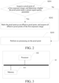
- FIG. 2 is a schematic flowchart of a method for acquiring an effective pixel point of a method for improving 3D image depth information according to another embodiment of the present invention. As shown in FIG. 2 , that the effective pixel point in the first exposure image is acquired in step S200 includes the following steps.
- Step S201 The pixel point of the first exposure image is acquired, and it is determined whether the pixel point meets a preset signal quality parameter.
- Step S202 If the pixel point meets the preset signal quality parameter, the pixel point is marked as an effective pixel point, and all effective pixel points of the first exposure image are acquired.
- Step S203 Any processing is not performed on the pixel point.
- all pixel points of the first exposure image are acquired, and it is sequentially determined whether a signal quality parameter of each pixel point meets the preset signal quality parameter. If the signal quality parameter of the pixel point meets the preset signal quality parameter, the pixel point is marked as an effective pixel point, all pixel points in the first exposure image are marked according to this principle, and all the effective pixel points marked in the first exposure image are acquired. If the signal quality parameter of the pixel point does not meet the preset signal quality parameter, any processing is not performed on the pixel point.
- the signal quality parameter includes, but is not limited to a signal amplitude and a signal-to-noise ratio.
- the signal amplitude is used as an example for description.
- the signal amplitude is agreed as follows: if the signal amplitude is marked as amp, amp ⁇ 100, it indicates that the reflected signal is too weak and is unreliable data that should be discarded; or if amp > 100 and amp ⁇ 1000, it indicates that the signal is normal and effective data; and if amp > 1000, it indicates that the pixel is a saturation pixel and is ineffective data that should be discarded. Therefore, it is determined whether the pixel point is effective, that is, it is determined whether the signal amplitude of the pixel point is between 100 and 1000.
- FIG. 3 is a structural diagram of hardware of an apparatus for improving 3D image depth information according to an embodiment of the present invention.
- the apparatus 10 for improving the 3D image depth information includes a memory 101 and a processor 102.
- the apparatus 10 for improving the 3D image depth information may be an independent electronic apparatus for processing a 3D image, for example, a photographing device such as a 3D camera, or may be an accessory apparatus attached to or coordinated with a photographing device such as a camera for achieving 3D image processing, such as an electronic device provided with a 3D camera or a UAV provided with a 3D camera.
- the memory 101 includes at least one type of readable storage medium, which includes a flash memory, a hard disk, a multimedia card, a card-type memory (for example, an SD, DX memory or the like), a random access memory (RAM), a static random access memory (SRAM), a read-only memory (ROM), an electrically erasable programmable read-only memory (EEPROM), a programmable read-only memory (PROM), a magnetic memory, a disk, disc, etc.
- the processor 102 may be a central processing unit (CPU), a controller, a microcontroller, a microprocessor, other data processing chips, or the like.
- FIG. 4 is a schematic diagram of a program module of an apparatus for improving 3D image depth information according to still another embodiment of the present invention.
- the apparatus 10 for improving the 3D image depth information includes an exposure module 100, a first effective pixel point extracting module 200, a second effective pixel point extracting module 300, and a demarcating and calibrating module 400.
- the module is configured to be executed by one or more processors (in this embodiment, the processor is a processor 102) to complete the present invention.
- the module in the present invention is a computer program segment that completes a specific function.
- the memory 101 is configured to store data such as program code of the apparatus 10 for improving the 3D image depth information.
- the processor 102 is configured to execute the program code stored in the memory 101.
- the exposure module 100 is configured to: acquire a raw 3D image, perform first-time exposure on the raw 3D image, and generate a first exposure image.
- the first effective pixel point extracting module 200 is configured to: acquire an effective pixel point in the first exposure image, and if a quantity of effective pixel points meets a preset condition, extract the effective pixel point in the first exposure image; otherwise, perform second-time exposure on the raw 3D image, and generate a second exposure image.
- the second effective pixel point extracting module 300 is configured to: if a quantity of effective pixel points in the second exposure image meets a preset condition, extract the effective pixel point in the second exposure image; otherwise, continuously perform exposure and generate a corresponding exposure image, determine whether the quantity of effective pixel points of the exposure image meets the preset condition until an exposure time reaches an exposure time threshold or a quantity of effective pixel points in the corresponding exposure image generated through exposure meets the preset condition, and extract the effective pixel point in the exposure image.
- the demarcating and calibrating module 400 is configured to demarcate and calibrate the effective pixel point, and generate a 3D depth information map.
- an unmanned aerial vehicle records a real-time video through a 3D camera, and needs to acquire a 3D depth image after processing each frame of image in the video, to determine a distance between the UAV and an obstacle.
- the exposure module 100 is configured to: acquire the raw 3D image, perform the first-time exposure on the raw 3D image, where an exposure time of the first-time exposure may be preset by a user, and acquire the first exposure image generated in the first-time exposure.
- the first effective pixel point extracting module 200 is configured to: acquire the first exposure image acquired from the exposure module 100, and acquire an effective pixel point in the first exposure image, where the effective pixel point refers to a pixel point that meets a preset signal quality parameter.
- the signal quality parameter includes, but is not limited to a signal amplitude and a signal-to-noise ratio.
- the preset signal quality parameter may be a preset signal amplitude interval, or a preset signal-to-noise ratio interval.
- the preset condition includes, but is not limited to a threshold of the quantity of the effective pixel points. For example, if the quantity of effective pixel points in the first exposure image meets a preset threshold of the quality of effective pixel points, the effective pixel point in the first exposure image is extracted.
- second-time exposure is performed on the raw 3D image.
- a second-time exposure time is different from a first-time exposure time.
- the second-time exposure time is longer than the first-time exposure time, and a second exposure image generated in the second-time exposure is acquired.
- the second effective pixel point extracting module 300 is configured to: acquire the second exposure image in the first effective pixel point extracting module 200, and if a quantity of effective pixel points in the second exposure image meets a preset condition, extract the effective pixel point in the second exposure image; if the quantity of effective pixel points in the second exposure image does not meet the preset condition, continuously perform exposure and generate a corresponding exposure image, in this case, continuously determine whether the quantity of effective pixel points of the exposure image meets the preset condition until an exposure time reaches an exposure time threshold or a quantity of effective pixel points in the corresponding exposure image generated through exposure meets the preset condition, and extract the effective pixel point in the corresponding exposure image.
- the preset condition is that the quality of effective pixel points generated through exposure exceeds a certain trigger quantity, or the quantity of effective pixel points generated through exposure is equal to a quantity of pixel points of the image.
- the trigger quantity is a quantity of preset thresholds, the trigger quantity being less than the quantity of pixel points of the exposure image. For example, if the quantity of pixel points in the exposure image is 200 and the trigger quantity is 180, it is detected that the quantity of effective pixel points generated through exposure exceeds 180. In this case, it indicates that the effective pixel points in the exposure image meet the preset condition.
- the demarcating and calibrating module 400 is configured to sequentially demarcate and calibrate the effective pixel points, and generate a 3D depth information map of high quality.
- a demarcation and calibration method is specifically performed according to a parameter of the 3D camera.
- the apparatus further includes: a preset module configured to preset an exposure time gradient array, the gradient array including exposure times with several time lengths arranged in ascending order, where an exposure time with the maximum time length is the exposure time threshold.
- a preset module configured to preset an exposure time gradient array, the gradient array including exposure times with several time lengths arranged in ascending order, where an exposure time with the maximum time length is the exposure time threshold.
- the preset module is configured to preset an exposure time gradient array, the exposure time gradient array being a gradient array with known time lengths, and time lengths being arranged in ascending order. After each exposure is performed, it is determined, depending on whether the quantity of effective pixel points meets the preset condition, whether next exposure is performed, and if not, a next larger gradient value in the exposure time gradient array is selected as the exposure time.
- the exposure module 100 is further configured to:
- the exposure module 100 is further configured to: after the 3D camera photographs a raw 3D image, acquire the exposure time in a pre-tuned exposure time gradient array as the first exposure time.
- the exposure time with a minimum time length in the exposure time gradient array is used as the first exposure time.
- the first-time exposure is performed on the acquired raw 3D image according to the first exposure time, and the first exposure image is generated.
- the first effective pixel point extracting module 200 is further configured to: if the quantity of effective pixel points in the first exposure image does not meet the preset condition, acquire a second exposure time greater than the first exposure time and adjacent to the first exposure time in the exposure time gradient array, perform the second-time exposure on the raw 3D image, and generate the second exposure image.
- the first effective pixel point extracting module 200 is further configured to: if the quantity of effective pixel points in the first exposure image does not meet the preset condition, acquire the second exposure time greater than the first exposure time and adjacent to the first exposure time in the exposure time gradient array, perform the second-time exposure on the raw 3D image according to the second exposure time, and generate the second exposure image, where the second exposure time is a next gradient array of the first exposure time in the exposure time gradient array.
- the second effective pixel point extracting module 300 is further configured to: If the quantity of effective pixel points in the second exposure image does not meet the preset condition, acquire a third exposure time greater than the second exposure time and adjacent to the second exposure time in the exposure time gradient array, perform third-time exposure on the raw 3D image, and generate the third exposure image until the exposure time reaches the exposure time threshold or the quantity of effective pixel points in the corresponding image generated through exposure meets the preset condition.
- the second effective pixel point extracting module 300 is further configured to: if the quantity of effective pixel points in the second exposure image does not meet the preset condition, acquire the third exposure time greater than the second exposure time and adjacent to the second exposure time in the exposure time gradient array, perform the third-time exposure on the raw 3D image, and generate the third exposure image. If the third exposure time is an exposure time threshold in the exposure time gradient array, regardless of whether an effective pixel point marked in the third exposure image meets the preset condition, acquisition of the effective pixel point ends, and the effective pixel point in the third exposure image is extracted.
- the first effective pixel point extracting module 200 is further configured to:
- the first effective pixel point extracting module 200 is further configured to: acquire the pixel point of the first exposure image, and determine whether a signal quality parameter of the pixel point meets the preset signal quality parameter, if the signal quality parameter of the pixel point meets the preset signal quality parameter, mark the pixel point as an effective pixel point, mark all pixel points in the first exposure image according to this principle, and acquire all the effective pixel points in the first exposure image.
- the signal quality parameter includes, but is not limited to a signal amplitude and a signal-to-noise ratio.
- the signal amplitude is used as an example for description.
- the signal amplitude is agreed as follows: if the signal amplitude is marked as amp, amp ⁇ 100, it indicates that the reflected signal is too weak and is unreliable data that should be discarded; or if amp > 100 and amp ⁇ 1000, it indicates that the signal is normal and effective data; and if amp > 1000, it indicates that the pixel is a saturation pixel and is ineffective data that should be discarded. Therefore, it is determined whether the pixel point is effective, that is, it is determined whether the signal amplitude of the pixel point is between 100 and 1000.
- UAV 600 an unmanned aerial vehicle (UAV) 600.
- the UAV 600 includes a housing 610, an arm 620, a motor 630 mounted onto the arm 620; a propeller 640 including a hub 641 and a blade 642, the hub 641 being connected to a rotating shaft of the motor 630, when the rotating shaft of the motor 630 rotates, the blade 642 being driven to rotate to produce a force that causes the UAV 600 to move; a camera 650 mounted onto the housing 610; and a processor 660 configured to perform step S100 to step S800 in the method in FIG. 1 , step S201 to step S203 in the method in FIG. 2 , and implement functions of the modules 100-400 in FIG. 4 .
- An embodiment of the present invention provides a non-volatile computer readable storage medium storing a computer executable instruction that, when executed by one or more processors, causes the processor to perform, for example, step S100 to step S800 in the method in FIG. 1 , step S201 to step S203 in the method in FIG. 2 , and implement functions of the modules 100-400 in FIG. 4 .
- Another embodiment of the present invention provides a computer program product that includes a computer program stored in a non-volatile computer readable storage medium, the computer program including a program instruction that, when executed by a processor, causes the processor to perform the foregoing method for improving the 3D image depth information, for example, perform step S100 to step S800 in the method in FIG. 1 , step S201 to step S203 in the method in FIG. 2 , and implement functions of the modules 100-400 in FIG. 4 .
- the apparatus embodiment described above is merely exemplary, and the modules described as separate components may or may not be physically separate, the components displayed as units may or may not be physical units, that is, may be located in one place, or may be distributed on a plurality of network units. Part or all of the modules may be selected according to actual needs to achieve the objective of the solution of this embodiment.
- the embodiments can be implemented by means of software plus a general hardware platform, and certainly, can also be implemented by hardware.
- the above-mentioned technical solution in essence or the part that contributes to the related technology can be embodied in the form of a software product, which can exist in a computer-readable storage medium, such as ROM / RAM, magnetic disk , An optical disc, and the like, including a number of instructions for causing a computer device (which may be a personal computer, a server, or a network device, etc.) to perform the methods described in various embodiments or certain parts of the embodiments.
Landscapes
- Engineering & Computer Science (AREA)
- Physics & Mathematics (AREA)
- General Physics & Mathematics (AREA)
- Computer Networks & Wireless Communication (AREA)
- Radar, Positioning & Navigation (AREA)
- Remote Sensing (AREA)
- Theoretical Computer Science (AREA)
- Computer Vision & Pattern Recognition (AREA)
- Electromagnetism (AREA)
- Signal Processing (AREA)
- Multimedia (AREA)
- Aviation & Aerospace Engineering (AREA)
- Studio Devices (AREA)
- Processing Or Creating Images (AREA)
Claims (10)
- Méthode d'amélioration des informations de profondeur d'une image 3D, dans laquelle la méthode comprend :acquérir (5100) une image 3D brute, effectuer une première exposition sur l'image 3D brute et générer une première image d'exposition ;acquérir (S200) un point de pixel effectif dans la première image d'exposition, et si une quantité de points de pixel effectifs remplit une condition prédéfinie, extraire (S300) le point de pixel effectif dans la première image d'exposition ; sinon, effectuer (S400) une seconde exposition sur l'image 3D brute, et générer une seconde image d'exposition ; etsi (S500) une quantité de points de pixels effectifs dans la seconde image d'exposition remplit la condition prédéfinie, extraire (S600) le point de pixel effectif dans la seconde image d'exposition ; sinon, effectuer en continu (S700) l'exposition et générer une image d'exposition correspondante, déterminer si la quantité de points de pixels effectifs de l'image d'exposition remplit la condition prédéfinie jusqu'à ce qu'un temps d'exposition atteigne un seuil de temps d'exposition ou qu'une quantité de points de pixels effectifs dans l'image d'exposition correspondante générée par l'exposition remplisse la condition prédéfinie, et extraire un point de pixel effectif dans l'image d'exposition ; etdélimiter et calibrer le point de pixel effectif, et générer (S800) une carte d'informations de profondeur en 3D ;dans lequel l'acquisition d'un point de pixel effectif dans la première image d'exposition comprend spécifiquement :acquérir (S201) le point de pixel de la première image d'exposition et déterminer si le point de pixel répond à un paramètre de qualité de signal prédéfini ; etsi le point de pixel satisfait au paramètre de qualité du signal prédéfini, marquer (S202) le point de pixel comme point de pixel effectif et acquérir tous les points de pixel effectifs dans la première image d'exposition ;dans lequelavant l'acquisition (S 100) d'une image 3D brute, effectuer une première exposition sur l'image 3D brute et générer une première image d'exposition, comprenant en outre :
le réglage d'un tableau de gradient de temps d'exposition, le tableau de gradient comprenant des temps d'exposition avec plusieurs longueurs de temps disposées dans l'ordre croissant, dans lequel un temps d'exposition avec la longueur de temps maximale est un seuil de temps d'exposition. - Méthode d'amélioration des informations de profondeur de l'image 3D selon la revendication 1, dans laquelle l'acquisition d'une image 3D brute, l'exécution d'une première exposition sur l'image 3D brute et la génération d'une première image d'exposition comprennent :acquérir l'image 3D brute, et acquérir un temps d'exposition de la matrice de gradient de temps d'exposition en tant que premier temps d'exposition ; eteffectuer la première exposition sur l'image 3D brute en fonction du premier temps d'exposition, et générer la première image d'exposition.
- Méthode d'amélioration des informations de profondeur de l'image 3D selon la revendication 2, dans laquelle la réalisation d'une seconde exposition sur l'image 3D brute et la génération d'une seconde image d'exposition comprennent :
si la quantité de points de pixels effectifs dans la première image d'exposition ne remplit pas la condition prédéfinie, acquérir un deuxième temps d'exposition supérieur au premier temps d'exposition et adjacent au premier temps d'exposition dans le réseau de gradients de temps d'exposition, effectuer le deuxième temps d'exposition sur l'image 3D brute, et générer la deuxième image d'exposition. - Méthode d'amélioration des informations de profondeur d'une image 3D selon la revendication 3, dans laquelle l'exposition et la génération d'une image d'exposition correspondante jusqu'à ce qu'un temps d'exposition atteigne un seuil de temps d'exposition ou qu'une quantité de points de pixels effectifs dans l'image correspondante générée par l'exposition satisfasse à la condition prédéfinie, comprennent :
si la quantité de points de pixels effectifs dans la deuxième image d'exposition ne remplit pas la condition prédéfinie, acquérir un troisième temps d'exposition supérieur au deuxième temps d'exposition et adjacent au deuxième temps d'exposition dans le réseau de gradients de temps d'exposition, effectuer une troisième exposition sur l'image 3D brute et générer la troisième image d'exposition jusqu'à ce que le temps d'exposition atteigne le seuil de temps d'exposition ou que la quantité de points de pixels effectifs dans l'image correspondante générée par l'exposition remplisse la condition prédéfinie. - Appareil permettant d'améliorer les informations de profondeur d'une image 3D, comprenant : une mémoire (101), un processeur (102) et un programme d'ordinateur stocké dans la mémoire et exécutable sur le processeur, lorsque le programme d'ordinateur est exécuté par le processeur, les étapes précédentes étant mises en oeuvre :acquérir une image 3D brute, effectuer une première exposition sur l'image 3D brute et générer une première image d'exposition ;acquérir un point de pixel effectif dans la première image d'exposition, et si une quantité de points de pixel effectifs remplit une condition prédéfinie, extraire le point de pixel effectif dans la première image d'exposition ; sinon, effectuer une seconde exposition sur l'image 3D brute, et générer une seconde image d'exposition ; etsi une quantité de points de pixels effectifs dans la seconde image d'exposition remplit la condition prédéfinie, extraire le point de pixel effectif dans la seconde image d'exposition ; sinon, effectuer une exposition en continu et générer une image d'exposition correspondante, déterminer si la quantité de points de pixels effectifs de l'image d'exposition remplit la condition prédéfinie jusqu'à ce qu'un temps d'exposition atteigne un seuil de temps d'exposition ou qu'une quantité de points de pixels effectifs dans l'image d'exposition correspondante générée par l'exposition remplisse la condition prédéfinie, et extraire le point de pixel effectif dans l'image d'exposition ; etdélimiter et calibrer le point de pixel effectif, et générer une carte d'informations de profondeur en 3D ;lorsque le programme informatique est exécuté par le processeur, les étapes suivantes sont mises en oeuvre :acquérir le point de pixel de la première image d'exposition et déterminer si le point de pixel répond à un paramètre de qualité de signal prédéfini ; etsi le point de pixel satisfait au paramètre de qualité du signal prédéfini, marquer le point de pixel comme point de pixel effectif et acquérir tous les points de pixel effectifs dans la première image d'exposition ;lorsque le programme informatique est exécuté par le processeur, les étapes suivantes sont mises en oeuvre :
prérégler un tableau de gradient de temps d'exposition, le tableau de gradient comprenant des temps d'exposition avec plusieurs longueurs de temps disposées dans l'ordre croissant, dans lequel un temps d'exposition avec la longueur de temps maximale est un seuil de temps d'exposition. - Appareil pour améliorer les informations de profondeur d'une image 3D selon la revendication 5, dans lequel, lorsque le programme informatique est exécuté par le processeur, les étapes suivantes sont mises en oeuvre :acquérir l'image 3D brute, et acquérir un temps d'exposition de la matrice de gradient de temps d'exposition en tant que premier temps d'exposition ; eteffectuer la première exposition sur l'image 3D brute en fonction du premier temps d'exposition, et générer la première image d'exposition.
- Appareil pour améliorer les informations de profondeur d'une image 3D selon la revendication 6, dans lequel, lorsque le programme informatique est exécuté par le processeur, les étapes suivantes sont mises en oeuvre :
si la quantité de points de pixels effectifs dans la première image d'exposition ne remplit pas la condition prédéfinie, acquérir un deuxième temps d'exposition supérieur au premier temps d'exposition et adjacent au premier temps d'exposition dans le réseau de gradients de temps d'exposition, effectuer le deuxième temps d'exposition sur l'image 3D brute, et générer la deuxième image d'exposition. - Appareil pour améliorer les informations de profondeur d'une image 3D selon la revendication 7, dans lequel, lorsque le programme informatique est exécuté par le processeur, les étapes suivantes sont mises en oeuvre :
si la quantité de points de pixels effectifs dans la deuxième image d'exposition ne remplit pas la condition prédéfinie, acquérir un troisième temps d'exposition supérieur au deuxième temps d'exposition et adjacent au deuxième temps d'exposition dans le réseau de gradients de temps d'exposition, effectuer une troisième exposition sur l'image 3D brute et générer la troisième image d'exposition jusqu'à ce que le temps d'exposition atteigne le seuil de temps d'exposition ou que la quantité de points de pixels effectifs dans l'image correspondante générée par l'exposition remplisse la condition prédéfinie. - Un véhicule aérien sans pilote, UAV, comprenant :un boîtier (610) ;un bras (620) ;un moteur (630) monté sur le bras ;une hélice (640) comprenant un moyeu (641) et une pale (642), le moyeu étant relié à un arbre rotatif du moteur, lorsque l'arbre rotatif du moteur tourne, la pale est entraînée en rotation pour produire une force qui fait bouger le drone ;une caméra (650) montée sur le boîtier ; etun processeur (660) configuré pour exécuter la méthode selon l'une des revendications 1 à 4.
- Support de stockage lisible par ordinateur non volatil, dans lequel le support de stockage lisible par ordinateur non volatil stocke une instruction exécutable par ordinateur qui, lorsqu'elle est exécutée par un ou plusieurs processeurs, amène le ou les processeurs à exécuter la méthode selon l'une des revendications 1 à 4.
Applications Claiming Priority (2)
| Application Number | Priority Date | Filing Date | Title |
|---|---|---|---|
| CN201710714161.0A CN109398731B (zh) | 2017-08-18 | 2017-08-18 | 一种提升3d图像深度信息的方法、装置及无人机 |
| PCT/CN2018/084072 WO2019033777A1 (fr) | 2017-08-18 | 2018-04-23 | Procédé et dispositif d'amélioration d'informations de profondeur d'une image 3d et véhicule aérien sans pilote |
Publications (3)
| Publication Number | Publication Date |
|---|---|
| EP3663791A1 EP3663791A1 (fr) | 2020-06-10 |
| EP3663791A4 EP3663791A4 (fr) | 2020-06-17 |
| EP3663791B1 true EP3663791B1 (fr) | 2023-05-31 |
Family
ID=65362068
Family Applications (1)
| Application Number | Title | Priority Date | Filing Date |
|---|---|---|---|
| EP18846940.7A Active EP3663791B1 (fr) | 2017-08-18 | 2018-04-23 | Procédé et dispositif d'amélioration d'informations de profondeur d'une image 3d et véhicule aérien sans pilote |
Country Status (4)
| Country | Link |
|---|---|
| US (1) | US11030762B2 (fr) |
| EP (1) | EP3663791B1 (fr) |
| CN (1) | CN109398731B (fr) |
| WO (1) | WO2019033777A1 (fr) |
Cited By (1)
| Publication number | Priority date | Publication date | Assignee | Title |
|---|---|---|---|---|
| EP4513232A1 (fr) * | 2023-08-25 | 2025-02-26 | Infineon Technologies AG | Puce semi-conductrice et procédé de réglage d'un temps d'exposition d'un capteur de temps de vol |
Families Citing this family (8)
| Publication number | Priority date | Publication date | Assignee | Title |
|---|---|---|---|---|
| CN111982291B (zh) * | 2019-05-23 | 2022-11-04 | 杭州海康机器人技术有限公司 | 一种基于无人机的火点定位方法、装置及系统 |
| CN112150529B (zh) * | 2019-06-28 | 2023-09-01 | 北京地平线机器人技术研发有限公司 | 一种图像特征点的深度信息确定方法及装置 |
| CN110428381B (zh) * | 2019-07-31 | 2022-05-06 | Oppo广东移动通信有限公司 | 图像处理方法、图像处理装置、移动终端及存储介质 |
| CN110475078B (zh) * | 2019-09-03 | 2020-12-15 | 河北科技大学 | 摄像机曝光时间调整方法及终端设备 |
| JP7436428B2 (ja) * | 2021-06-25 | 2024-02-21 | 株式会社日立エルジーデータストレージ | 測距装置、測距システム、及び、干渉回避方法 |
| CN114581387B (zh) * | 2022-02-24 | 2025-07-18 | 昆山丘钛光电科技有限公司 | 图像处理方法、装置、终端设备及存储介质 |
| CN116184364B (zh) * | 2023-04-27 | 2023-07-07 | 上海杰茗科技有限公司 | 一种iToF相机的多机干扰检测与去除方法及装置 |
| CN120009191B (zh) * | 2025-04-22 | 2025-08-15 | 合肥埃科光电科技股份有限公司 | 一种表面缺陷检测方法、装置、系统及介质 |
Family Cites Families (10)
| Publication number | Priority date | Publication date | Assignee | Title |
|---|---|---|---|---|
| CN105898273B (zh) * | 2011-01-07 | 2018-04-10 | 索尼互动娱乐美国有限责任公司 | 二维图像的再投影的多样本解析 |
| US9807322B2 (en) * | 2013-03-15 | 2017-10-31 | Duelight Llc | Systems and methods for a digital image sensor |
| EP3015882B1 (fr) * | 2013-06-27 | 2020-12-09 | Panasonic Semiconductor Solutions Co., Ltd. | Dispositif de mesure de distance |
| CN104853080B (zh) * | 2014-02-13 | 2018-05-11 | 宏达国际电子股份有限公司 | 图像处理装置 |
| JP6424338B2 (ja) * | 2014-06-09 | 2018-11-21 | パナソニックIpマネジメント株式会社 | 測距装置 |
| JP2016540440A (ja) * | 2014-06-12 | 2016-12-22 | エスゼット ディージェイアイ テクノロジー カンパニー リミテッドSz Dji Technology Co.,Ltd | ピクチャー処理方法、装置 |
| US10062201B2 (en) * | 2015-04-21 | 2018-08-28 | Microsoft Technology Licensing, Llc | Time-of-flight simulation of multipath light phenomena |
| CN104994309B (zh) * | 2015-07-07 | 2017-09-19 | 广东欧珀移动通信有限公司 | 一种消除相机光斑的方法及系统 |
| US9594381B1 (en) * | 2015-09-24 | 2017-03-14 | Kespry, Inc. | Enhanced distance detection system |
| CN105611185B (zh) * | 2015-12-18 | 2017-10-31 | 广东欧珀移动通信有限公司 | 图像生成方法、装置及终端设备 |
-
2017
- 2017-08-18 CN CN201710714161.0A patent/CN109398731B/zh active Active
-
2018
- 2018-04-23 WO PCT/CN2018/084072 patent/WO2019033777A1/fr not_active Ceased
- 2018-04-23 EP EP18846940.7A patent/EP3663791B1/fr active Active
-
2020
- 2020-02-18 US US16/793,931 patent/US11030762B2/en active Active
Cited By (1)
| Publication number | Priority date | Publication date | Assignee | Title |
|---|---|---|---|---|
| EP4513232A1 (fr) * | 2023-08-25 | 2025-02-26 | Infineon Technologies AG | Puce semi-conductrice et procédé de réglage d'un temps d'exposition d'un capteur de temps de vol |
Also Published As
| Publication number | Publication date |
|---|---|
| EP3663791A1 (fr) | 2020-06-10 |
| EP3663791A4 (fr) | 2020-06-17 |
| WO2019033777A1 (fr) | 2019-02-21 |
| US20200184666A1 (en) | 2020-06-11 |
| CN109398731B (zh) | 2020-09-08 |
| US11030762B2 (en) | 2021-06-08 |
| CN109398731A (zh) | 2019-03-01 |
Similar Documents
| Publication | Publication Date | Title |
|---|---|---|
| EP3663791B1 (fr) | Procédé et dispositif d'amélioration d'informations de profondeur d'une image 3d et véhicule aérien sans pilote | |
| CN112106111B (zh) | 一种标定方法、设备、可移动平台及存储介质 | |
| US11196919B2 (en) | Image processing method, electronic apparatus, and computer-readable storage medium | |
| AU2018405051B2 (en) | Image collection control method and device, image collection system and TOF camera | |
| CN112017251B (zh) | 标定方法、装置、路侧设备和计算机可读存储介质 | |
| US11019322B2 (en) | Estimation system and automobile | |
| CN106851238B (zh) | 白平衡控制方法、白平衡控制装置及电子装置 | |
| JP2022505772A (ja) | 構造化光照明付き飛行時間型センサ | |
| JP2023026503A (ja) | 車両の周囲を特徴付けるためのシステム | |
| US10055881B2 (en) | Video imaging to assess specularity | |
| US20220046177A1 (en) | Control device, camera device, movable object, control method, and program | |
| CN110716586A (zh) | 无人机的拍照控制方法、装置、无人机和存储介质 | |
| KR102772501B1 (ko) | 카메라 고유 파라미터에 대한 온라인 평가 | |
| CN114391114B (zh) | 物体识别用异常检测装置及其方法、以及存储介质 | |
| CN114365189A (zh) | 影像配准装置、图像生成系统、影像配准方法及影像配准程序 | |
| WO2019163118A1 (fr) | Système informatique, procédé de commande de drone, et programme | |
| CN112771575A (zh) | 距离确定方法、可移动平台及计算机可读存储介质 | |
| WO2023286542A1 (fr) | Dispositif de détection d'objet et procédé de détection d'objet | |
| JPWO2023089984A5 (fr) | ||
| TWI793477B (zh) | 船舶輔助校正系統及其運作方法 | |
| JP2022011685A (ja) | 制御装置、撮像装置、制御方法、及びプログラム | |
| JP7242822B2 (ja) | 推定システムおよび自動車 | |
| KR20210037778A (ko) | 왜곡 영상 내에 gt 영역 설정 방법 및 장치 | |
| WO2021031833A1 (fr) | Dispositif de commande, système de photographie, procédé de commande, et programme | |
| CN107025665A (zh) | 结合深度信息的图像去雾方法及装置和电子装置 |
Legal Events
| Date | Code | Title | Description |
|---|---|---|---|
| STAA | Information on the status of an ep patent application or granted ep patent |
Free format text: STATUS: THE INTERNATIONAL PUBLICATION HAS BEEN MADE |
|
| PUAI | Public reference made under article 153(3) epc to a published international application that has entered the european phase |
Free format text: ORIGINAL CODE: 0009012 |
|
| STAA | Information on the status of an ep patent application or granted ep patent |
Free format text: STATUS: REQUEST FOR EXAMINATION WAS MADE |
|
| 17P | Request for examination filed |
Effective date: 20200304 |
|
| AK | Designated contracting states |
Kind code of ref document: A1 Designated state(s): AL AT BE BG CH CY CZ DE DK EE ES FI FR GB GR HR HU IE IS IT LI LT LU LV MC MK MT NL NO PL PT RO RS SE SI SK SM TR |
|
| AX | Request for extension of the european patent |
Extension state: BA ME |
|
| A4 | Supplementary search report drawn up and despatched |
Effective date: 20200515 |
|
| RIC1 | Information provided on ipc code assigned before grant |
Ipc: H04N 5/235 20060101ALI20200511BHEP Ipc: G06T 5/50 20060101ALI20200511BHEP Ipc: B64D 47/08 20060101ALI20200511BHEP Ipc: G01S 17/933 20200101ALI20200511BHEP Ipc: G01S 7/48 20060101AFI20200511BHEP Ipc: G01S 7/486 20200101ALI20200511BHEP |
|
| DAV | Request for validation of the european patent (deleted) | ||
| DAX | Request for extension of the european patent (deleted) | ||
| STAA | Information on the status of an ep patent application or granted ep patent |
Free format text: STATUS: EXAMINATION IS IN PROGRESS |
|
| 17Q | First examination report despatched |
Effective date: 20210629 |
|
| REG | Reference to a national code |
Ref country code: DE Ref legal event code: R079 Free format text: PREVIOUS MAIN CLASS: G01S0007480000 Ipc: G01S0017100000 Ref country code: DE Ref legal event code: R079 Ref document number: 602018050550 Country of ref document: DE Free format text: PREVIOUS MAIN CLASS: G01S0007480000 Ipc: G01S0017100000 |
|
| GRAP | Despatch of communication of intention to grant a patent |
Free format text: ORIGINAL CODE: EPIDOSNIGR1 |
|
| STAA | Information on the status of an ep patent application or granted ep patent |
Free format text: STATUS: GRANT OF PATENT IS INTENDED |
|
| RIC1 | Information provided on ipc code assigned before grant |
Ipc: G06T 5/50 20060101ALI20230118BHEP Ipc: G01S 7/486 20060101ALI20230118BHEP Ipc: G01S 17/933 20200101ALI20230118BHEP Ipc: B64D 47/08 20060101ALI20230118BHEP Ipc: H04N 23/70 20230101ALI20230118BHEP Ipc: G01S 7/497 20060101ALI20230118BHEP Ipc: G01S 7/4912 20200101ALI20230118BHEP Ipc: G01S 17/89 20060101ALI20230118BHEP Ipc: G01S 17/36 20060101ALI20230118BHEP Ipc: G01S 17/10 20060101AFI20230118BHEP |
|
| INTG | Intention to grant announced |
Effective date: 20230209 |
|
| GRAS | Grant fee paid |
Free format text: ORIGINAL CODE: EPIDOSNIGR3 |
|
| GRAA | (expected) grant |
Free format text: ORIGINAL CODE: 0009210 |
|
| STAA | Information on the status of an ep patent application or granted ep patent |
Free format text: STATUS: THE PATENT HAS BEEN GRANTED |
|
| AK | Designated contracting states |
Kind code of ref document: B1 Designated state(s): AL AT BE BG CH CY CZ DE DK EE ES FI FR GB GR HR HU IE IS IT LI LT LU LV MC MK MT NL NO PL PT RO RS SE SI SK SM TR |
|
| REG | Reference to a national code |
Ref country code: GB Ref legal event code: FG4D Ref country code: CH Ref legal event code: EP |
|
| REG | Reference to a national code |
Ref country code: AT Ref legal event code: REF Ref document number: 1571248 Country of ref document: AT Kind code of ref document: T Effective date: 20230615 Ref country code: DE Ref legal event code: R096 Ref document number: 602018050550 Country of ref document: DE |
|
| REG | Reference to a national code |
Ref country code: IE Ref legal event code: FG4D |
|
| REG | Reference to a national code |
Ref country code: LT Ref legal event code: MG9D |
|
| REG | Reference to a national code |
Ref country code: NL Ref legal event code: MP Effective date: 20230531 |
|
| REG | Reference to a national code |
Ref country code: AT Ref legal event code: MK05 Ref document number: 1571248 Country of ref document: AT Kind code of ref document: T Effective date: 20230531 |
|
| PG25 | Lapsed in a contracting state [announced via postgrant information from national office to epo] |
Ref country code: SE Free format text: LAPSE BECAUSE OF FAILURE TO SUBMIT A TRANSLATION OF THE DESCRIPTION OR TO PAY THE FEE WITHIN THE PRESCRIBED TIME-LIMIT Effective date: 20230531 Ref country code: NO Free format text: LAPSE BECAUSE OF FAILURE TO SUBMIT A TRANSLATION OF THE DESCRIPTION OR TO PAY THE FEE WITHIN THE PRESCRIBED TIME-LIMIT Effective date: 20230831 Ref country code: ES Free format text: LAPSE BECAUSE OF FAILURE TO SUBMIT A TRANSLATION OF THE DESCRIPTION OR TO PAY THE FEE WITHIN THE PRESCRIBED TIME-LIMIT Effective date: 20230531 Ref country code: AT Free format text: LAPSE BECAUSE OF FAILURE TO SUBMIT A TRANSLATION OF THE DESCRIPTION OR TO PAY THE FEE WITHIN THE PRESCRIBED TIME-LIMIT Effective date: 20230531 |
|
| PG25 | Lapsed in a contracting state [announced via postgrant information from national office to epo] |
Ref country code: RS Free format text: LAPSE BECAUSE OF FAILURE TO SUBMIT A TRANSLATION OF THE DESCRIPTION OR TO PAY THE FEE WITHIN THE PRESCRIBED TIME-LIMIT Effective date: 20230531 Ref country code: PL Free format text: LAPSE BECAUSE OF FAILURE TO SUBMIT A TRANSLATION OF THE DESCRIPTION OR TO PAY THE FEE WITHIN THE PRESCRIBED TIME-LIMIT Effective date: 20230531 Ref country code: NL Free format text: LAPSE BECAUSE OF FAILURE TO SUBMIT A TRANSLATION OF THE DESCRIPTION OR TO PAY THE FEE WITHIN THE PRESCRIBED TIME-LIMIT Effective date: 20230531 Ref country code: LV Free format text: LAPSE BECAUSE OF FAILURE TO SUBMIT A TRANSLATION OF THE DESCRIPTION OR TO PAY THE FEE WITHIN THE PRESCRIBED TIME-LIMIT Effective date: 20230531 Ref country code: LT Free format text: LAPSE BECAUSE OF FAILURE TO SUBMIT A TRANSLATION OF THE DESCRIPTION OR TO PAY THE FEE WITHIN THE PRESCRIBED TIME-LIMIT Effective date: 20230531 Ref country code: IS Free format text: LAPSE BECAUSE OF FAILURE TO SUBMIT A TRANSLATION OF THE DESCRIPTION OR TO PAY THE FEE WITHIN THE PRESCRIBED TIME-LIMIT Effective date: 20230930 Ref country code: HR Free format text: LAPSE BECAUSE OF FAILURE TO SUBMIT A TRANSLATION OF THE DESCRIPTION OR TO PAY THE FEE WITHIN THE PRESCRIBED TIME-LIMIT Effective date: 20230531 Ref country code: GR Free format text: LAPSE BECAUSE OF FAILURE TO SUBMIT A TRANSLATION OF THE DESCRIPTION OR TO PAY THE FEE WITHIN THE PRESCRIBED TIME-LIMIT Effective date: 20230901 |
|
| PG25 | Lapsed in a contracting state [announced via postgrant information from national office to epo] |
Ref country code: FI Free format text: LAPSE BECAUSE OF FAILURE TO SUBMIT A TRANSLATION OF THE DESCRIPTION OR TO PAY THE FEE WITHIN THE PRESCRIBED TIME-LIMIT Effective date: 20230531 |
|
| PG25 | Lapsed in a contracting state [announced via postgrant information from national office to epo] |
Ref country code: SK Free format text: LAPSE BECAUSE OF FAILURE TO SUBMIT A TRANSLATION OF THE DESCRIPTION OR TO PAY THE FEE WITHIN THE PRESCRIBED TIME-LIMIT Effective date: 20230531 |
|
| PG25 | Lapsed in a contracting state [announced via postgrant information from national office to epo] |
Ref country code: SM Free format text: LAPSE BECAUSE OF FAILURE TO SUBMIT A TRANSLATION OF THE DESCRIPTION OR TO PAY THE FEE WITHIN THE PRESCRIBED TIME-LIMIT Effective date: 20230531 Ref country code: SK Free format text: LAPSE BECAUSE OF FAILURE TO SUBMIT A TRANSLATION OF THE DESCRIPTION OR TO PAY THE FEE WITHIN THE PRESCRIBED TIME-LIMIT Effective date: 20230531 Ref country code: RO Free format text: LAPSE BECAUSE OF FAILURE TO SUBMIT A TRANSLATION OF THE DESCRIPTION OR TO PAY THE FEE WITHIN THE PRESCRIBED TIME-LIMIT Effective date: 20230531 Ref country code: PT Free format text: LAPSE BECAUSE OF FAILURE TO SUBMIT A TRANSLATION OF THE DESCRIPTION OR TO PAY THE FEE WITHIN THE PRESCRIBED TIME-LIMIT Effective date: 20231002 Ref country code: EE Free format text: LAPSE BECAUSE OF FAILURE TO SUBMIT A TRANSLATION OF THE DESCRIPTION OR TO PAY THE FEE WITHIN THE PRESCRIBED TIME-LIMIT Effective date: 20230531 Ref country code: DK Free format text: LAPSE BECAUSE OF FAILURE TO SUBMIT A TRANSLATION OF THE DESCRIPTION OR TO PAY THE FEE WITHIN THE PRESCRIBED TIME-LIMIT Effective date: 20230531 Ref country code: CZ Free format text: LAPSE BECAUSE OF FAILURE TO SUBMIT A TRANSLATION OF THE DESCRIPTION OR TO PAY THE FEE WITHIN THE PRESCRIBED TIME-LIMIT Effective date: 20230531 |
|
| REG | Reference to a national code |
Ref country code: DE Ref legal event code: R097 Ref document number: 602018050550 Country of ref document: DE |
|
| PLBE | No opposition filed within time limit |
Free format text: ORIGINAL CODE: 0009261 |
|
| STAA | Information on the status of an ep patent application or granted ep patent |
Free format text: STATUS: NO OPPOSITION FILED WITHIN TIME LIMIT |
|
| PG25 | Lapsed in a contracting state [announced via postgrant information from national office to epo] |
Ref country code: SI Free format text: LAPSE BECAUSE OF FAILURE TO SUBMIT A TRANSLATION OF THE DESCRIPTION OR TO PAY THE FEE WITHIN THE PRESCRIBED TIME-LIMIT Effective date: 20230531 |
|
| 26N | No opposition filed |
Effective date: 20240301 |
|
| PG25 | Lapsed in a contracting state [announced via postgrant information from national office to epo] |
Ref country code: SI Free format text: LAPSE BECAUSE OF FAILURE TO SUBMIT A TRANSLATION OF THE DESCRIPTION OR TO PAY THE FEE WITHIN THE PRESCRIBED TIME-LIMIT Effective date: 20230531 Ref country code: IT Free format text: LAPSE BECAUSE OF FAILURE TO SUBMIT A TRANSLATION OF THE DESCRIPTION OR TO PAY THE FEE WITHIN THE PRESCRIBED TIME-LIMIT Effective date: 20230531 |
|
| PGFP | Annual fee paid to national office [announced via postgrant information from national office to epo] |
Ref country code: GB Payment date: 20240419 Year of fee payment: 7 |
|
| PG25 | Lapsed in a contracting state [announced via postgrant information from national office to epo] |
Ref country code: BG Free format text: LAPSE BECAUSE OF FAILURE TO SUBMIT A TRANSLATION OF THE DESCRIPTION OR TO PAY THE FEE WITHIN THE PRESCRIBED TIME-LIMIT Effective date: 20230531 |
|
| PG25 | Lapsed in a contracting state [announced via postgrant information from national office to epo] |
Ref country code: MC Free format text: LAPSE BECAUSE OF FAILURE TO SUBMIT A TRANSLATION OF THE DESCRIPTION OR TO PAY THE FEE WITHIN THE PRESCRIBED TIME-LIMIT Effective date: 20230531 |
|
| PG25 | Lapsed in a contracting state [announced via postgrant information from national office to epo] |
Ref country code: MC Free format text: LAPSE BECAUSE OF FAILURE TO SUBMIT A TRANSLATION OF THE DESCRIPTION OR TO PAY THE FEE WITHIN THE PRESCRIBED TIME-LIMIT Effective date: 20230531 Ref country code: BG Free format text: LAPSE BECAUSE OF FAILURE TO SUBMIT A TRANSLATION OF THE DESCRIPTION OR TO PAY THE FEE WITHIN THE PRESCRIBED TIME-LIMIT Effective date: 20230531 |
|
| REG | Reference to a national code |
Ref country code: CH Ref legal event code: PL |
|
| PG25 | Lapsed in a contracting state [announced via postgrant information from national office to epo] |
Ref country code: LU Free format text: LAPSE BECAUSE OF NON-PAYMENT OF DUE FEES Effective date: 20240423 |
|
| REG | Reference to a national code |
Ref country code: BE Ref legal event code: MM Effective date: 20240430 |
|
| PG25 | Lapsed in a contracting state [announced via postgrant information from national office to epo] |
Ref country code: LU Free format text: LAPSE BECAUSE OF NON-PAYMENT OF DUE FEES Effective date: 20240423 |
|
| PG25 | Lapsed in a contracting state [announced via postgrant information from national office to epo] |
Ref country code: BE Free format text: LAPSE BECAUSE OF NON-PAYMENT OF DUE FEES Effective date: 20240430 |
|
| PG25 | Lapsed in a contracting state [announced via postgrant information from national office to epo] |
Ref country code: BE Free format text: LAPSE BECAUSE OF NON-PAYMENT OF DUE FEES Effective date: 20240430 Ref country code: CH Free format text: LAPSE BECAUSE OF NON-PAYMENT OF DUE FEES Effective date: 20240430 |
|
| PG25 | Lapsed in a contracting state [announced via postgrant information from national office to epo] |
Ref country code: IE Free format text: LAPSE BECAUSE OF NON-PAYMENT OF DUE FEES Effective date: 20240423 |
|
| PGFP | Annual fee paid to national office [announced via postgrant information from national office to epo] |
Ref country code: DE Payment date: 20250422 Year of fee payment: 8 |
|
| PGFP | Annual fee paid to national office [announced via postgrant information from national office to epo] |
Ref country code: FR Payment date: 20250425 Year of fee payment: 8 |
|
| PG25 | Lapsed in a contracting state [announced via postgrant information from national office to epo] |
Ref country code: CY Free format text: LAPSE BECAUSE OF FAILURE TO SUBMIT A TRANSLATION OF THE DESCRIPTION OR TO PAY THE FEE WITHIN THE PRESCRIBED TIME-LIMIT; INVALID AB INITIO Effective date: 20180423 |
|
| PG25 | Lapsed in a contracting state [announced via postgrant information from national office to epo] |
Ref country code: HU Free format text: LAPSE BECAUSE OF FAILURE TO SUBMIT A TRANSLATION OF THE DESCRIPTION OR TO PAY THE FEE WITHIN THE PRESCRIBED TIME-LIMIT; INVALID AB INITIO Effective date: 20180423 |
|
| GBPC | Gb: european patent ceased through non-payment of renewal fee |
Effective date: 20250423 |
|
| PG25 | Lapsed in a contracting state [announced via postgrant information from national office to epo] |
Ref country code: GB Free format text: LAPSE BECAUSE OF NON-PAYMENT OF DUE FEES Effective date: 20250423 |