EP3663816A1 - Lichtstreuvorrichtungen zur verwendung in der photoimmuntherapie - Google Patents
Lichtstreuvorrichtungen zur verwendung in der photoimmuntherapie Download PDFInfo
- Publication number
- EP3663816A1 EP3663816A1 EP19214413.7A EP19214413A EP3663816A1 EP 3663816 A1 EP3663816 A1 EP 3663816A1 EP 19214413 A EP19214413 A EP 19214413A EP 3663816 A1 EP3663816 A1 EP 3663816A1
- Authority
- EP
- European Patent Office
- Prior art keywords
- fiber
- core
- light
- section
- circular
- Prior art date
- Legal status (The legal status is an assumption and is not a legal conclusion. Google has not performed a legal analysis and makes no representation as to the accuracy of the status listed.)
- Withdrawn
Links
Images














Classifications
-
- A—HUMAN NECESSITIES
- A61—MEDICAL OR VETERINARY SCIENCE; HYGIENE
- A61N—ELECTROTHERAPY; MAGNETOTHERAPY; RADIATION THERAPY; ULTRASOUND THERAPY
- A61N5/00—Radiation therapy
- A61N5/06—Radiation therapy using light
- A61N5/0613—Apparatus adapted for a specific treatment
- A61N5/062—Photodynamic therapy, i.e. excitation of an agent
-
- A—HUMAN NECESSITIES
- A61—MEDICAL OR VETERINARY SCIENCE; HYGIENE
- A61N—ELECTROTHERAPY; MAGNETOTHERAPY; RADIATION THERAPY; ULTRASOUND THERAPY
- A61N5/00—Radiation therapy
- A61N5/06—Radiation therapy using light
-
- A—HUMAN NECESSITIES
- A61—MEDICAL OR VETERINARY SCIENCE; HYGIENE
- A61N—ELECTROTHERAPY; MAGNETOTHERAPY; RADIATION THERAPY; ULTRASOUND THERAPY
- A61N5/00—Radiation therapy
- A61N5/06—Radiation therapy using light
- A61N5/0601—Apparatus for use inside the body
-
- A—HUMAN NECESSITIES
- A61—MEDICAL OR VETERINARY SCIENCE; HYGIENE
- A61N—ELECTROTHERAPY; MAGNETOTHERAPY; RADIATION THERAPY; ULTRASOUND THERAPY
- A61N5/00—Radiation therapy
- A61N5/06—Radiation therapy using light
- A61N5/067—Radiation therapy using light using laser light
-
- G—PHYSICS
- G02—OPTICS
- G02B—OPTICAL ELEMENTS, SYSTEMS OR APPARATUS
- G02B23/00—Telescopes, e.g. binoculars; Periscopes; Instruments for viewing the inside of hollow bodies; Viewfinders; Optical aiming or sighting devices
- G02B23/24—Instruments or systems for viewing the inside of hollow bodies, e.g. fibrescopes
- G02B23/2407—Optical details
- G02B23/2461—Illumination
- G02B23/2469—Illumination using optical fibres
-
- G—PHYSICS
- G02—OPTICS
- G02B—OPTICAL ELEMENTS, SYSTEMS OR APPARATUS
- G02B27/00—Optical systems or apparatus not provided for by any of the groups G02B1/00 - G02B26/00, G02B30/00
- G02B27/09—Beam shaping, e.g. changing the cross-sectional area, not otherwise provided for
- G02B27/0927—Systems for changing the beam intensity distribution, e.g. Gaussian to top-hat
-
- G—PHYSICS
- G02—OPTICS
- G02B—OPTICAL ELEMENTS, SYSTEMS OR APPARATUS
- G02B5/00—Optical elements other than lenses
- G02B5/02—Diffusing elements; Afocal elements
- G02B5/0205—Diffusing elements; Afocal elements characterised by the diffusing properties
- G02B5/021—Diffusing elements; Afocal elements characterised by the diffusing properties the diffusion taking place at the element's surface, e.g. by means of surface roughening or microprismatic structures
-
- G—PHYSICS
- G02—OPTICS
- G02B—OPTICAL ELEMENTS, SYSTEMS OR APPARATUS
- G02B6/00—Light guides; Structural details of arrangements comprising light guides and other optical elements, e.g. couplings
- G02B6/0001—Light guides; Structural details of arrangements comprising light guides and other optical elements, e.g. couplings specially adapted for lighting devices or systems
- G02B6/0005—Light guides; Structural details of arrangements comprising light guides and other optical elements, e.g. couplings specially adapted for lighting devices or systems the light guides being of the fibre type
- G02B6/0008—Light guides; Structural details of arrangements comprising light guides and other optical elements, e.g. couplings specially adapted for lighting devices or systems the light guides being of the fibre type the light being emitted at the end of the fibre
-
- G—PHYSICS
- G02—OPTICS
- G02B—OPTICAL ELEMENTS, SYSTEMS OR APPARATUS
- G02B6/00—Light guides; Structural details of arrangements comprising light guides and other optical elements, e.g. couplings
- G02B6/0001—Light guides; Structural details of arrangements comprising light guides and other optical elements, e.g. couplings specially adapted for lighting devices or systems
- G02B6/0005—Light guides; Structural details of arrangements comprising light guides and other optical elements, e.g. couplings specially adapted for lighting devices or systems the light guides being of the fibre type
- G02B6/001—Light guides; Structural details of arrangements comprising light guides and other optical elements, e.g. couplings specially adapted for lighting devices or systems the light guides being of the fibre type the light being emitted along at least a portion of the lateral surface of the fibre
-
- G—PHYSICS
- G02—OPTICS
- G02B—OPTICAL ELEMENTS, SYSTEMS OR APPARATUS
- G02B6/00—Light guides; Structural details of arrangements comprising light guides and other optical elements, e.g. couplings
- G02B6/02—Optical fibres with cladding with or without a coating
-
- G—PHYSICS
- G02—OPTICS
- G02B—OPTICAL ELEMENTS, SYSTEMS OR APPARATUS
- G02B6/00—Light guides; Structural details of arrangements comprising light guides and other optical elements, e.g. couplings
- G02B6/02—Optical fibres with cladding with or without a coating
- G02B6/02295—Microstructured optical fibre
- G02B6/02314—Plurality of longitudinal structures extending along optical fibre axis, e.g. holes
-
- G—PHYSICS
- G02—OPTICS
- G02B—OPTICAL ELEMENTS, SYSTEMS OR APPARATUS
- G02B6/00—Light guides; Structural details of arrangements comprising light guides and other optical elements, e.g. couplings
- G02B6/02—Optical fibres with cladding with or without a coating
- G02B6/036—Optical fibres with cladding with or without a coating core or cladding comprising multiple layers
-
- G—PHYSICS
- G02—OPTICS
- G02B—OPTICAL ELEMENTS, SYSTEMS OR APPARATUS
- G02B6/00—Light guides; Structural details of arrangements comprising light guides and other optical elements, e.g. couplings
- G02B6/24—Coupling light guides
- G02B6/241—Light guide terminations
-
- G—PHYSICS
- G02—OPTICS
- G02B—OPTICAL ELEMENTS, SYSTEMS OR APPARATUS
- G02B6/00—Light guides; Structural details of arrangements comprising light guides and other optical elements, e.g. couplings
- G02B6/24—Coupling light guides
- G02B6/26—Optical coupling means
- G02B6/262—Optical details of coupling light into, or out of, or between fibre ends, e.g. special fibre end shapes or associated optical elements
-
- A—HUMAN NECESSITIES
- A61—MEDICAL OR VETERINARY SCIENCE; HYGIENE
- A61B—DIAGNOSIS; SURGERY; IDENTIFICATION
- A61B18/00—Surgical instruments, devices or methods for transferring non-mechanical forms of energy to or from the body
- A61B18/18—Surgical instruments, devices or methods for transferring non-mechanical forms of energy to or from the body by applying electromagnetic radiation, e.g. microwaves
- A61B18/20—Surgical instruments, devices or methods for transferring non-mechanical forms of energy to or from the body by applying electromagnetic radiation, e.g. microwaves using laser
- A61B2018/2035—Beam shaping or redirecting; Optical components therefor
- A61B2018/20554—Arrangements for particular intensity distribution, e.g. tophat
-
- A—HUMAN NECESSITIES
- A61—MEDICAL OR VETERINARY SCIENCE; HYGIENE
- A61N—ELECTROTHERAPY; MAGNETOTHERAPY; RADIATION THERAPY; ULTRASOUND THERAPY
- A61N5/00—Radiation therapy
- A61N5/06—Radiation therapy using light
- A61N5/0601—Apparatus for use inside the body
- A61N2005/0612—Apparatus for use inside the body using probes penetrating tissue; interstitial probes
-
- A—HUMAN NECESSITIES
- A61—MEDICAL OR VETERINARY SCIENCE; HYGIENE
- A61N—ELECTROTHERAPY; MAGNETOTHERAPY; RADIATION THERAPY; ULTRASOUND THERAPY
- A61N5/00—Radiation therapy
- A61N5/06—Radiation therapy using light
- A61N2005/063—Radiation therapy using light comprising light transmitting means, e.g. optical fibres
-
- A—HUMAN NECESSITIES
- A61—MEDICAL OR VETERINARY SCIENCE; HYGIENE
- A61N—ELECTROTHERAPY; MAGNETOTHERAPY; RADIATION THERAPY; ULTRASOUND THERAPY
- A61N5/00—Radiation therapy
- A61N5/06—Radiation therapy using light
- A61N2005/0664—Details
-
- G—PHYSICS
- G02—OPTICS
- G02B—OPTICAL ELEMENTS, SYSTEMS OR APPARATUS
- G02B5/00—Optical elements other than lenses
- G02B5/02—Diffusing elements; Afocal elements
- G02B5/0205—Diffusing elements; Afocal elements characterised by the diffusing properties
- G02B5/021—Diffusing elements; Afocal elements characterised by the diffusing properties the diffusion taking place at the element's surface, e.g. by means of surface roughening or microprismatic structures
- G02B5/0221—Diffusing elements; Afocal elements characterised by the diffusing properties the diffusion taking place at the element's surface, e.g. by means of surface roughening or microprismatic structures the surface having an irregular structure
-
- G—PHYSICS
- G02—OPTICS
- G02B—OPTICAL ELEMENTS, SYSTEMS OR APPARATUS
- G02B5/00—Optical elements other than lenses
- G02B5/02—Diffusing elements; Afocal elements
- G02B5/0205—Diffusing elements; Afocal elements characterised by the diffusing properties
- G02B5/021—Diffusing elements; Afocal elements characterised by the diffusing properties the diffusion taking place at the element's surface, e.g. by means of surface roughening or microprismatic structures
- G02B5/0226—Diffusing elements; Afocal elements characterised by the diffusing properties the diffusion taking place at the element's surface, e.g. by means of surface roughening or microprismatic structures having particles on the surface
Definitions
- the present invention relates to a medical device for performing photoimmunotherapy (“PIT”), photodynamic therapy (“PDT”) or other light activated treatments upon tissue of an organism, cellular or acellular organisms and methods of using such medical device in PIT, PDT or other light activated therapies. More particularly, the invention is a fiber optic diffuser device to deliver light in a desired illumination pattern and wavelength for PIT, PDT or other light therapies to an area under treatment.
- PIT photoimmunotherapy
- PDT photodynamic therapy
- the invention is a fiber optic diffuser device to deliver light in a desired illumination pattern and wavelength for PIT, PDT or other light therapies to an area under treatment.
- PIT, PDT and other light activated therapies have been used to treat various maladies and diseases.
- PIT and PDT and other light activated therapies often involve the use of an exogenous or endogenous photosensitizing agent or substance that is activated by electromagnetic radiation (e.g., light such as laser light, LED light, etc.).
- PIT is based on a new drug system that consists of a cancer targeting monoclonal antibody conjugated to a photoactivatable molecule.
- the targeting agent can include other moieties such as ligands, viral capsid, peptides, liposomes, nanoparticles, etc. This drug conjugate is not pharmacologically active until the conjugate is bound to the cancer cells and gains anticancer activity upon light-mediated activation at the tumor site.
- Tumor targeting and context precision activation of the drug provides extremely cancer specificity and permits rapid cancer cell killing without damage to the surrounding healthy tissues.
- Anticancer activity of PIT is highly effective and it works with multiple types of monoclonal antibodies and other targeting moieties, thus the platform enables the targeting of a broad range of cancer antigens and tumor types.
- the present invention is not limited to targeting tumor sites. Instead, the present invention can also be used to target other cellular and acellular organisms including bacteria, fungi, viruses, prions, etc. in order to treat or prevent disease(s).
- PIT and/or PDT light sources are to match the activation spectrum of the exogenous or endogenous photosensitizer (usually the wavelength of peak absorbance) and to generate adequate power at this wavelength, deliverable to the target tissue ergonomically and with high efficiency.
- the sources typically, 1-5 W of usable power are required in the 630-850 nm range at irradiances of up to several hundred mW cm -2 in order to deliver treatments in tens of minutes.
- the sources must be reliable in the clinical environment and be cost-effective.
- treatment area For illumination of the area to be treated ("treatment area"), usually cylindrical and frontal (superficial) diffusers, sometimes also called “micro lens diffusers", are generally used.
- the fiber optic cylindrical (side firing) and superficial (front firing) diffusers consist of multimode fiber assemblies with a round core/cladding structure from 50-1000um core diameter with attached diffusing section that can be connected directly to a light source, for instance by means of an optical connector.
- FIG. 1 shows an example of a typical commercially available cylindrical light diffusing device 100 comprising an optical connector 10 connecting to a light source (not shown) on one end, an optical fiber 12 and a cylindrical diffuser 16 on the other end.
- the optical fiber 12 is in light communication with the cylindrical diffuser 16 causing the cylindrical diffuser 16 to out-couple light in a longitudinally radial-symmetric irradiance distribution 18 across the longitudinal length 19 of the cylindrical diffuser 16.
- FIG. 2 A map of the irradiance at a vertical (i.e., latitudinal) cross-section (shown as "11" in FIG. 1 ) through the core of the optical fiber 12 taken just before the optical fiber 12 enters the cylindrical diffuser 16 is shown in FIG. 2 .
- the light source used is a 690 nm laser with 1 Watt launch power and this power was adjusted until the irradiance 18 measured at the center 17 of the longitudinal length of the diffuser 16 was 150 mW/cm 2 . This measurement is taken 0.75 mm from the central axis of the stated location of the diffuser 16.
- the optical fiber 12 from the light source leading up to the cylindrical diffuser 16 (“lead fiber") is 2 meters long.
- the optical fiber 12 has a 700 ⁇ m outer diameter ("OD”) glass core and a 740 ⁇ m OD cladding. During operation, the optical fiber 12 is filled with laser light having an angular distribution of a numerical aperture ("NA") of 0.22.
- NA numerical aperture
- the cross-section 11 was taken after 2 meter lead fiber (12).
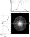
- the associated irradiance distribution graphs of FIG. 2 taken from vertical and horizontal cross sections through the center of the map of the irradiance show that there is poor spatial uniformity of the irradiance distribution in the core of the optical fiber 12 ("core irradiance distribution").
- the large values in the center of the graphs show that there is significantly higher irradiance in the center of the fiber core than near its edges.
- both graphs have two axes: one axis shows width (e.g., diameter) in mm and the other axis shows irradiance in Watt/cm 2 .
- the out-coupled longitudinally radially-symmetric irradiance distribution along the outer surface of irradiance emitting section of the cylindrical diffuser 16 also demonstrates poor spatial uniformity leading to a non-ideal irradiance distribution as shown in FIG. 3 .
- This uneven irradiance distribution is undesirable because the irradiance uniformity would not satisfy the needs of a proper "dosimetry", meaning the correct irradiance in light power/surface area for an optimal medical treatment efficacy.
- the horizontal axis shows the longitudinal length (in mm) used to measure the length 19 of the cylindrical diffuser 16 and the vertical axis shows the out-coupled irradiance at the surface of the cylindrical diffuser 16 measured in Watts/cm 2 at a distance 0.75 mm from the central axis.
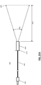
- FIG. 4 is an example for a typical commercially available cylindrical light diffusing device 200 comprising an optical connector 20 connecting to a light source (not shown) on one end, an optical fiber 22 and a cylindrical diffuser 26 on the other end.
- the optical fiber 22 is in light communication with a mode mixer 24 and the cylindrical diffuser 26 causing the cylindrical diffuser 26 to out-couple light in a longitudinally radial-symmetric irradiance distribution 28 across the longitudinal length 29 of the cylindrical diffuser 26.
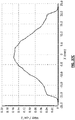
- FIG. 5 shows a map of the irradiance at a vertical cross-section (shown as "21" in FIG. 4 ) through the core of the optical fiber 22 taken just before the optical fiber 22 enters the cylindrical diffuser 26.
- the light source used is a 690 nm laser with 1 Watt launch power and this power was adjusted until the irradiance 28 measured at the center 27 of the longitudinal length of the diffuser 26 was 150 mW/cm 2 . This measurement is taken 0.75 mm from the central axis of the stated location of the diffuser 26.
- the optical fiber 22 from the light source leading up to the cylindrical diffuser 26 (“lead fiber") is 2 meters long.
- the optical fiber 22 has a 700 ⁇ m OD glass core and a 740 ⁇ m OD cladding. During operation, the optical fiber 22 is filled with laser light having an angular distribution of a numerical aperture ("NA") of 0.22. The cross-section 21 was taken after 2 meter lead fiber (22). Unlike FIG. 2 , the associated irradiance distribution graphs shown in FIG.
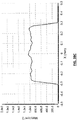
- the out-coupled longitudinally radially-symmetric irradiance distribution along the outer surface of irradiance emitting section of the cylindrical diffuser 26 shows spatial uniformity leading to an optimal "top hat” diffusing irradiance distribution as shown in FIG. 6.
- FIG. 6 shows that the variation of the out-coupled irradiance distribution should be a "top hat" with less than +/- 20% of the average ("I 0 ") optical irradiance for a cylindrical diffuser in terms of the radially emitted irradiance distribution (e.g., optimal diffusing irradiance distribution).
- FIG. 6 shows longitudinal length in mm and the horizontal arrow indicates the length 29 of the cylindrical diffuser 26.
- the vertical axis of FIG. 6 shows the out-coupled irradiance at the surface of the cylindrical diffuser 26 measured in Watts/cm 2 at a distance 0.75 mm from the central axis.
- optimal mode mixing e.g., with an effective mode mixer
- the mode mixer 24 shown in FIG. 4 is created in the optical fiber 22 by a series of five consecutive alternating tight radius bends.
- Another conventional mode mixing method (not shown) is to wrap the optical fiber 22 tightly multiple times around an object (e.g. a mandrel). These popular forms of mode mixing create spatial uniformity at the expense of increased transmission losses, often resulting in the losses of 50% or more. Additionally, these techniques also create stress points within the optical fiber 22.
- an effective mode mixer by itself is insufficient to achieve the "top hat” diffusing irradiance distribution.
- An effective light diffuser or diffusing section is also required.
- the diffuser section commonly uses additional elements and/or processing of the diffuser section in order to achieve the "top hat" diffusing irradiance distribution.
- one conventional method is removing the cladding of the fiber tip 30 (the diffusing section) and etching the exposed fiber core with hydrofluoric acid or grinding it on a polishing apparatus. The resulting conical tip with its frosted appearance is then covered with a protective transparent envelope 32. Referring to FIG.
- a separate diffuser 34 containing scattering medium 36 that is composed of micron-sized titanium oxide (TiO 2 ) particles embedded in clear epoxy or silicone elastomer, which is encased in a protective Teflon sheath 38.
- a reflector 40 attached to a plastic plug 42 is then inserted into the open distal end of the sheath 38.
- the purpose of the coated plug 42 is to reflect any light that survives forward propagation back through the scattering medium 36 where it can be re-distributed, thus improving the uniformity of the emission profile.
- Yet another method of construction can be described as a hybrid of the two previous methods wherein the cladding of an optical fiber is removed mechanically leaving the surface of the core roughened.
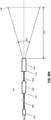
- an exemplary embodiment of a typical frontal (superficial) diffuser 500 is provided with 690 nm light introduced onto an optical fiber 506 (e.g., a cylindrical optical fiber) with a 550 um diameter core via a fiber optic connector 503.
- an optical fiber 506 e.g., a cylindrical optical fiber
- a 1 ⁇ 4 pitch, 1 mm diameter graded index (“GRIN") lens component 504 located at the distal end output face 510 of the optical fiber 506 generates the outcoupled light 502. Since the desired treatment area (i.e., target) 508 has a much larger diameter (e.g. 42 mm) than the diameter of the optical fiber 506 (e.g.
- the effect of the lens component 504, to a first approximation, is to form an image of the output face 510 of the optical fiber 506 onto the target 508 where the target 508 is located at some standoff distance 512 (e.g., 64 mm) away from the lens component 504.
- some standoff distance 512 e.g. 64 mm
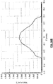
- the spatial irradiance distribution of a cross section along the target 508, as shown in FIG. 37C is closely related to the spatial irradiance distribution along a cross section of 510, as shown in FIG. 37B .
- this exemplary embodiment exhibits low loss (e.g., -0.25 dB), where 1.0 Watt input power is enough to generate the irradiance distribution in FIG. 37C .
- the fiber spatial irradiance distribution at 510 of a cylindrical fiber 506 is typically non-uniform, resulting on a non-uniform target spatial irradiance distribution at the target 508. This is not ideal for PIT and PDT application where a constant, uniform spatial irradiance distribution is required over the whole treatment area target 508.
- the typical prior art addresses the issue of the non-uniform target spatial irradiance distribution at the target 508 as shown in FIG. 37C by including a mode mixing section 520 in the fiber 506 at a predetermined distanced location prior to the lens component 504.
- the effect of the mode mixing section 520 is to convert the non-uniform cross sectional spatial irradiance distribution at 510, as shown in FIG. 38B , to the significantly more uniform cross sectional spatial irradiance distribution at 514, as shown in FIG. 38C . Therefore, as shown in FIG. 38D , the target spatial irradiance distribution created by the lens component 504 at the target 508 will have a spatial irradiance distribution that is also more uniform.
- the typical prior art mode mixing section 520 not only produces a more uniform fiber spatial irradiance distribution but it also creates a more uniform angular intensity distribution at the output of the fiber 506.
- the angular intensity distribution is not as important as the spatial irradiance distribution. This because the image formed by the projection lens 504 is essentially mapping all the light from one location in the fiber 506 to a location on the target 508, regardless of emission angle.
- the mode mixing section 520 found in the prior art can be constructed of a serpentine section of one or more tight radius bends as shown in FIGS. 39A-39B , a coiled section of tight radius loops as shown in FIG. 39C , or a section with multiple turns of a tight radius helix as shown in FIG. 39D .
- Other art-disclosed embodiments of the mode mixing section 520 may also be used (e.g., alternating sections of graded and step index fibers, etc.). However, all these techniques suffer from a significant drawback, they create good mode mixing at the expense of creating high losses in the mode mixing section 520.
- the configuration in FIG. 38A is identical to the configuration in FIG.
- the lens component 504 may be comprised of a combination of one or more of optical elements including spherical, aspherical, graded index and diffractive elements.
- the fiber 506 and lens 504 are often part of a disposable assembly and the lens component 504 tends to have a small diameter.
- the diverging nature of the typical projection lens 504 results in different beam sizes at target position locations 516, 508 and 518 located at stand-off distance 520, 512 and 522 respectively in FIG. 40A .
- the total power in the resulting beam is the same.
- the size of the irradiance distribution on the target locations gets larger with distance while the value of the irradiance drops.
- the present invention provides a light diffusing device 300 having a non-circular core fiber 302 that provides a "top hat" core irradiance distribution (i.e., optimal core irradiance distribution) without the necessity of using a mode mixer (e.g., 24 shown in FIG. 4 ).
- the light diffusing device 300 of the present invention emits irradiance in a radially symmetric longitudinally "top hat” diffusing irradiance distribution (i.e., optimal diffusing irradiance distribution) without the necessity of using the above-described known light diffusers and/or diffusing sections.
- the device 300 further includes a lead-in optical fiber 304 and at least one optical connector 306.
- one end of the lead-in optical fiber 304 is in light communication to a light source (not shown) while the other end of the lead-in optical fiber 304 is in light communication with the proximal end of the non-circular core fiber 302 through the at least one optical connector 306 as shown in FIGS. 9 and 11 .
- the non-circular core fiber 302 further includes a light diffusing section 308 having a diffusing proximal end 310 and a diffusing distal end 312.
- the light diffusing section 308 is located near the distal end of the non-circular core fiber 302.
- the non-circular core fiber 302 may optionally include a light blocking means 314 (e.g., physical cap, coating such as aluminum deposition, or the like) preventing superficial or frontal light emission from the distal end of the non-circular core fiber 302.
- the light blocking means 314 is a mirror that turns light around and reuses it while avoiding over illuminating the treatment area. It provides a highly efficient light diffusing device because only about 6% of the launched light couples back into the lead-in optical fiber 304.
- the lead-in optical fiber 304 is connected to the light source via an additional optical connector 306.
- the lead-in optical fiber 304 can be any conventional optical fiber including but not limited to the optical fiber (12, 22) described above.
- the at least one optical connector 306 connects and allows the lead-in optical fiber 304 to be in light communication with the non-circular core fiber 302 during operation.
- An alternative to the at least one optical connector 306 is a conventional glue joint or fusion joint between the lead-in optical fiber 304 and the non-circular core fiber 302.
- the non-circular core fiber 302 actually also serves as the lead-in optical fiber 304 (resulting in a single optical fiber) and is connected to a light source via the at least one optical connector 306, a glue/fusion joint, or other conventional connection means.
- the at least one optical connector 306 can be any art-disclosed optical connector (e.g., SMA connectors or the like).
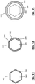
- FIGS. 13-18 each shows a vertical (i.e., latitudinal) cross-sectional view of the non-circular core fiber 302 at location 316, which is right before the diffusing proximal end 310 of the light diffusing section 308 (see FIGS. 9 and 11 ).
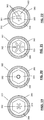
- FIGS. 10 , 12 and 19-22 each shows a vertical cross-sectional view of the diffusing distal end 312 of the light diffusing section 308 as shown in FIGS. 9 and 11 .
- the non-circular core fiber 302 includes a fiber core 350.
- the non-circular core fiber 302 may optionally include a cladding 352 as shown in FIGS. 10 , 12-14 and 16-18 .
- the fiber core 350 has a non-circular geometry such as hexagon (as shown in FIGS. 10 and 12-15 ), square (as shown in FIGS. 16-18 ), rectangle, triangle, octagon, other regular polygons and non-regular polygons. Accordingly, there is a wide range of potential non-circular core shapes that can achieve homogeneous irradiance inside the core. Some shape characteristics make a shape particularly well suited for the present invention. Although radial symmetry is not required, it does provide the benefits of ease of manufacture and promoting radially symmetric output irradiance pattern. The inclusion of inflection points in the cross section profile where the tangent of the shape changes rapidly encourages better mixing by sending adjacent rays in different directions.
- facets also promotes better mixing by avoiding self-focusing behavior. Avoiding re-entrant geometry aides in manufacture and avoids physically weak structures. These shape characteristics combined tend to encourage the use of regular polygon shapes as the basis for the non-circular core geometry. It should also be noted that a core with a helical or twisted shape could also be of interest for generating spatially homogeneous irradiance in the core.
- the cladding 352 may have the same non-circular vertical (i.e., latitudinal) cross sectional geometry as the fiber core 350 (see e.g., FIGS. 12 , 13 , and 16 ).
- the cladding 352 may have a circular exterior surface geometry 354 with an interior surface geometry 356 that has the same general shape as the fiber core 350 (see e.g., FIGS. 10 , 14 , 17 and 18 ).
- the cladding 352 does not exist but is replaced with an enclosed open cavity or environment (e.g., air) 358 between the fiber core 350 and a covering 360 that is concentric with the fiber core 350 and radially envelopes (but does not tightly cladded) the fiber core 350.
- the covering 360 can be any suitable art-disclosed polymeric material (e.g., Pebax®) and is generally circular in shape as shown in FIGS. 11, 12 , 15 , 18-22 .
- the covering 360 offers additional protection for the non-circular core fiber 302.
- the covering 360 can be clear or translucent. If clear, the covering 360 does not provide any light scattering thus no extra losses of light. If translucent, internal scattering by the covering 360 can assist in improving the uniformity of the diffusing irradiance distribution. However, too much internal scattering by the covering 360 can cause excess losses of light due to absorption.
- a vertical cross sectional view of the non-circular core fiber 302 shows its fiber core 350 has a square geometry.
- the interior surface geometry 356 of its cladding 352 matched this square geometry while the exterior surface geometry 354 of its cladding 352 is circular in shape.
- the non-circular core fiber 302 further includes the enclosed open cavity 358, which is sandwiched between the cladding 352 and the covering 360.
- the covering 360 has a circular geometry.
- the fiber core 350 of the non-circular core fiber 302 is constructed out of poly (methyl methacrylate) ("PMMA") with a hexagonal geometry in a circumscribed ⁇ 660 ⁇ m diameter circle.
- PMMA poly (methyl methacrylate)
- the fiber core 350 is clad by the cladding 352 with an interior surface geometry 356 that has the same hexagonal geometry as the fiber core 350.
- the exterior surface geometry 354 of the cladding 352 is circular.
- the cladding 352 is constructed of a silicone with an ⁇ 740 ⁇ m OD.
- the lead-in fiber 304 of the device 300 has a 200 ⁇ m OD glass core and a 230 ⁇ m OD cladding.
- the length of the non-circular core fiber 302 is 30 cm.
- the core optical fiber 302 is filled with laser light having an angular distribution of a NA of 0.22.
- other embodiments could include different materials for both the core and cladding, including utilizing various transparent or translucent glasses and polymers. If the total length of the diffuser is short, then absorbance is not of primary concern, but the materials should not be opaque at the wavelengths of interest. For example, if the diffuser is to be used to provide UV illumination then a silica core light guide is appropriate, whereas use of mid wave IR light would encourage the use of a fluorite or silver halide glass.
- injection moldable polymer materials are appropriate for visible and near IR applications, including but not limited to PMMA, poly carbonate (PC) and polystyrene (PS).
- PC poly carbonate
- PS polystyrene
- Various castable materials including epoxies and silicones are also of interest. In all cases, care should be utilized to ensure the materials could handle the required amount of optical power without ill effects, such as melting or crazing.
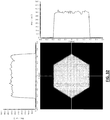
- FIG. 27 shows a map of the irradiance at the vertical cross-section (shown as "316" in FIG. 9 ) through the fiber core 350 taken just before the diffusing proximal end 310.
- the light source used is a 690 nm laser with 0.125 Watt launch power and this power was adjusted until the irradiance measured at the center 307 of the longitudinally length of the light diffusing section 308 was 150 mW/cm 2 . This measurement is taken 0.75 mm from the central axis of the stated location of the light diffusing section 308.
- the total length of optical fiber (combination of the lead-in fiber 304 and the non-circular core fiber 302) from the light source leading up to this location 316 is 2 meter long.
- the associated irradiance distribution graphs shown in FIG. 27 taken from vertical and horizontal cross sections through the center of the map of the irradiance show the same "top hat" core irradiance distribution as the above-discussed conventional cylindrical light diffusing device 200 (shown in FIG. 5 ), which requires a mode mixer (24).
- This "top hat" core irradiance distribution indicates a high degree of uniformity of the irradiance distribution in the fiber core 350 (i.e., optimal core irradiance distribution).
- Topic hat core irradiance distribution and/or optimal core irradiance distribution shall be defined hereinafter in this Specification as having all irradiance of a cross-section of the fiber core 350 to be within at least +/- 20% of the average irradiance of the cross-section of the fiber core 350, indicating a high degree of uniformity of the irradiance distribution in the core of the fiber 22.
- the at least +/-20% value can be further reduced to +/- 15% range, or even +/- 10% range.
- FIG. 30 shows a vertical cross-sectional view of a circular shaped core fiber 301 where the projected path of a propagating skew ray 366 that always stays near the edge of the fiber core 351.
- meridional rays 368 with paths that lie on a plane so that rays that start on the central axis of the light guide always cross back though the central axis of the fiber core 351.
- FIG. 29 which shows a vertical cross-sectional view of a square shaped non-circular core fiber 302 with the projected path of similar propagating rays.
- the skew ray 370 still propagates without crossing the central axis of the fiber core 350, but now its path is such that its energy can at some locations be found near the edges of the fiber core 350 while in other locations it can be found closer the center of the fiber core 350.
- a meridional ray 372 that starts on the central axis of the fiber core 350 can have a path that samples much of the area of the fiber core 350 without ever crossing the axis again.
- the fiber core 350 of FIG. 13 is same as the fiber core 350 shown in FIG. 14 . They both are constructed out of PMMA with a hexagonal geometry in a circumscribed ⁇ 660 ⁇ m diameter circle.
- the non-circular core fiber 302 of FIG. 13 differs from the core fiber of FIG. 14 because the cladding 352 of FIG. 13 has a hexagonal geometry.
- the cladding 352 of FIG. 13 is constructed of a fluorinated polymer in a circumscribed ⁇ 740 um diameter circle.
- the fiber core 350 has the same geometry and dimensions as the fiber core of FIG. 14 except that it is constructed out of polystyrene instead of PMMA.
- the non-circular core fiber 302 of FIG. 15 does not have the cladding 352. Instead, it (302) further includes the enclosed open cavity 358 and the covering 360.
- the covering 360 is constructed of a translucent Pebax® resin with an ⁇ 1000 ⁇ m OD and an ⁇ 900 ⁇ m inner diameter ("ID").
- ID ⁇ 1000 ⁇ m OD
- the trapped air contained in open cavity 358 acts as a cladding to ensure the light is contained within the fiber core 350.
- the exemplary embodiments shown in FIGS. 16-17 use the same fiber core 350 constructed out of PMMA with a 500 ⁇ m x 500 ⁇ m square geometry.
- the non-circular core fiber 302 of FIG. 16 has a cladding 352 constructed out of fluorinated polymer with a 540 ⁇ m x 540 ⁇ m square geometry.
- the non-circular core fiber 302 of FIG. 17 has a different cladding 352 as it has a square interior surface geometry 356 and a circular exterior surface geometry 354.
- the cladding 352 is constructed of a silicone with an ⁇ 740 ⁇ m diameter OD.
- the fiber core 350 has the same geometry and dimensions as the fiber core 350 of FIG. 17 except that it is constructed out of polystyrene instead of PMMA. Both have the same cladding 352.
- the non-circular core fiber 302 of FIG. 18 further includes the enclosed open cavity 358 and the covering 360.
- the covering 360 is constructed of a translucent Pebax® resin with an ⁇ 1000 ⁇ m OD and an ⁇ 900 ⁇ m ID.
- the non-circular core fiber 302 is a combination of the core fiber shown in FIG. 13 plus the enclosed open cavity 358 and the covering 360.
- the covering 360 is constructed of a translucent Pebax® resin with an ⁇ 1000 ⁇ m OD and an ⁇ 900 ⁇ m ID.
- the non-circular core fiber 302 of the present invention with its variety of shapes, materials, cladding (352), and covering (360) can provide "top hat” core irradiance distribution without needing a mode mixer thus providing a less expensive and sturdier light diffusing device (300).
- the non-circular core fiber 302 of the present invention can be used in conjunction with one of the above-described conventional lighting diffusers or diffusing sections to provide "top hat" diffusing irradiance distribution.
- the device 300 In order for the device 300 to provide a "top hat" diffusing irradiance distribution without using such a conventional light diffuser or diffusing section, the device 300 must include internal (i.e., not reaching the exterior surface of the fiber core 350) scattering features 362, preferably inscribed or written by laser, within the light diffusing section 308 as shown in FIGS. 9 and 11 .
- the "top hat" diffusing irradiance distribution is defined in this Specification as having a longitudinal variation of the out-coupled irradiance to be less than +/- 20% of the average ("I 0 ") optical irradiance for a cylindrical diffuser in terms of the radially emitted irradiance distribution (see e.g., FIG. 6 ), indicating a high degree of uniformity.
- the at least +/- 20% value can be further reduced to +/- 15% range, or even +/- 10% range.
- the internal scattering features 362 generally begin at the diffusing proximal end 310 and end at the diffusing distal end 312.
- the features 362 can be in a variety of shapes and patterns as shown in FIGS. 10 , 12 , 19-22 .
- FIGS. 10 , 12 , 19-22 show a vertical (i.e., latitudinal) cross-sectional view of the diffusing distal end 312 of the light diffusing section 308.
- the features 362 can be (i) three cylinders oriented around the central axis of the fiber core 350 at 60° increments as shown in FIGS. 10 , 12 and 19 (ii) a single line of spheres concentric to the central axis of the fiber core 350 as shown in FIG.
- a symmetrical array of elliptical features e.g., features that are elliptical or spherical
- elliptical features e.g., features that are elliptical or spherical
- a pair of parallel cylinders 361 where each cylinder of a pair are located at a predetermined distance from the central axis of the fiber core 350, with subsequent pairs of cylinders that are located at different longitudinal locations along the length of the light diffusing section 308 are oriented at different angles around the central axis of the fiber core 350, (e.g.
- the pair of parallel cylinders 363 are located at a different cross section of the fiber and are clocked at 60° relative to the pair 361). Please note that while the embodiments discussed herein use 60° increments, other predetermined patterns such may also be suitable such as, without limitations, 45°, 72°, 90°, 120°, 180° increments.
- Each scattering feature 362 can be created by a suitable art-disclosed laser.
- a focused, mode-locked 532 nm 10 pico-second laser pulse at 1.5 Watts average power can create the features 362 shown in FIG. 10 , which are comprised of three cylinders, each approximately 27 ⁇ m in diameter and 270 ⁇ m in length oriented around the central axis of the fiber core 350 at 60° increments.
- a series of 520 nm 400 femto-second laser pulses at 2.0 Watts average power focused through an objective lens with a numerical aperture of 0.4 can create the features 362 shown in FIG.
- the scattering characteristics of each of the features 362 are varied by material, geometry and processing.
- the proportion of light scattered per length or per feature 362 must increase as the density of light per length in the light diffusing section 308 decreases due to light being scattered out of the non-circular core fiber 302. This can be achieved by changing the number of features 362 per unit length or the size of the features 362 as a function of length. Depending on the amount of return light acceptable, linear increase in size may suffice but a non-linear increase in size vs length may be preferred. In another exemplary embodiment, the number of features 362 per unit length may increase while the size of the features 362 as a function of length may decrease. It should be noted that it is also possible for one skilled in the art to change the processing parameters in order to change the amount of scattering per feature 362.
- the internal scattering features 362 are distributed in the light diffusing section 308 along the central axis 364 of the non-circular fiber core 350 as shown in FIGS. 9 and 11 , the light propagates down the light diffusing section 308 and there is constant mixing occurring in the light diffusing section 308 itself. As the light in the center of the fiber core 350 encounters the internal scattering features 362 and is scattered out of the light diffusing section 308, the light redistribution ensures the irradiance in the center of the fiber core 350 is replenished.
- the feature 362 can also be longitudinally spaced in a variety of patterns.
- the features 362 can be arranged longitudinally in a uniform linear manner concentric with the central axis 364 of the fiber core 350 as shown in FIG. 23 .
- the features 362 can be arranged longitudinally in a non-uniform linear manner by changing the number of the features 362 per unit length as shown in FIG. 24 . In FIG. 24 , the number of features 362 per unit length increases going from the diffusing proximal end 310 to the diffusing distal end 312 of the light diffusing section 308.
- the number of features 362 per unit length may decrease going from the diffusing proximal end 310 to the diffusing distal end 312 of the light diffusing section 308 but size of the features 362 may increase going from the diffusing proximal end 310 to the diffusing distal end 312 of the light diffusing section 308.
- the features 362 can be arranged longitudinally in a uniform linear manner with a linear increase in size as shown in FIG. 25 .
- the features 362 can be arranged longitudinally in a uniform manner with a non-linear increase in size as shown in FIG. 26 .
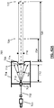
- the present invention provides a frontal light diffusing device 600 including a fiber optic connector 603, a cylindrical optical fiber section 602, a non-circular core fiber section 604, a fiber splice 605 joining the two fiber sections, and a lens component 606.
- the cylindrical optical fiber section 602 is in light communication with the non-circular core fiber section 604, and the non-circular core fiber section 604 is also in light communication with the lens component 606.
- the non-circular core fiber section 604 can have the same characteristics as the above-discussed non-circular core fiber 302 which provides a "top hat" core irradiance distribution (without the necessity of using a mode mixer) except that it does not include the optional light blocking means 314 discussed above.
- the cross section can also vary down the longitudinal length of the non-circular core fiber section 604 to assist in creating a better mixing effect, e.g.
- the core of 604 can have varying amounts of twist (i.e., rotation around the longitudinal axis of the fiber section 604) instead of a straight extrusion, or the non-circular profile of 604 can vary from one shape to another (e.g. hexagonal to square).
- the non-circular core fiber section 604 acts as a spatial mode mixer to cause several internal bounces of the propagating light so that there is little to no loss of propagating light.
- the cylindrical optical fiber section 602 has the non-uniform fiber spatial irradiance distribution of light shown in FIG. 41B as measured at cross section 608.
- the non-circular core fiber section 604 outputs the significantly more uniform mixed fiber spatial irradiance distribution shown FIG. 41C as measured at cross section 610.
- the target spatial irradiance distribution shown in FIG. 41D created by lens component 606 at the target cross section 614 is also more uniform. Accordingly, both the mixed spatial irradiance distribution measured at 610 and the target spatial irradiance distribution measured at 614 have the desired "top hat" spatial irradiance distribution.
- top hat spatial irradiance distribution and/or optimal spatial irradiance distribution shall hereinafter be defined as having variation of the out-coupled spatial irradiance distribution be less than +/- 20% of the average ("I 0 ") optical irradiance for a frontal diffuser in terms of the emitted irradiance distribution, indicating a high degree of uniformity of the spatial irradiance distribution at the relevant location (e.g., at 610 and/or at target 614).
- the at least +/- 20% value can be further reduced to +/- 15% range, or even +/- 10% range.
- the mixing of propagation angles means that some rays of light that did propagate down the fiber core get perturbed into angles that exceed the critical angle of the fiber and are emitted, resulting in transmission loss and other unwanted effects like local heating of the surrounding materials.
- the non-circular core fiber section 604 does not change the angles such that they cannot propagate, they only re-arrange the paths of the rays while preserving the angle of each ray to the optical axis of the non-circular core fiber section 604.
- non-circular core fiber section 604 it is possible to create variations in the shape or size of the non-circular core fiber section 604 down the length of the mixing section so that controlled amounts of angular mixing can be included in the effect of the non-circular core fiber section 604, noting that any increased angular mixing will also be accompanied by incurring corresponding transmission losses.
- the non-circular core fiber section 604 can extend from the light source to the projection lens (e.g., 606) or, as shown in FIG. 41A , a short section 604 can be utilized after a cylindrical fiber section 602 and prior to the lens component 606. Note that if a section of cylindrical fiber 602 is used between the non-circular core fiber section 604 and the lens component 606, care should be utilized that it not be too long (e.g., less than 0.25 meters or the like) or the mixed spatial irradiance distribution measured prior to 606 can become non-uniform again.
- the non-circular core fiber section 604 can be a separate piece of material that is connected using standard fiber optic connectors 605 or can be permanently affixed to one end of the cylindrical fiber section 602 by glue or even melted into place by a fusion bonding technique (e.g., welding or the like). It is also possible to mold or emboss a non-cylindrical section 604 into an otherwise cylindrical section of fiber 602. Care should be taken to engineer the junction between the cylindrical fiber section 602 and the non-circular core fiber section 604 to minimized losses, e.g., matching sizes and maximum propagation angles.
- the non-circular fiber core section 604 is at least 50 mm in length and constructed out of glass with a hexagonal geometry of 600 ⁇ m ID, with a 680 ⁇ m OD cladding.
- the lens component 606 is comprised of a 1 ⁇ 4 pitch, 1 mm diameter GRIN lens.
- This embodiment demonstrates low transmission losses of -0.36 dB.
- the total length of optical fiber (combination of the cylindrical optical fiber section 602 and the non-circular core fiber section 604) from the light source to the projection lens 606 is 2 meter long.
- the cylindrical optical fiber section 602 has the non-uniform fiber spatial irradiance distribution of light shown in FIG. 41B as measured at cross section 608.
- the non-circular core fiber section 604 outputs the significantly more uniform mixed fiber spatial irradiance distribution shown FIG. 41C as measured at cross section 610.
- the target spatial irradiance distribution shown in FIG. 41D created by lens component 606 at the target cross section 614 is also more uniform. Accordingly, both the mixed spatial irradiance distribution measured at 610 and the target spatial irradiance distribution measured at 614 have the desired "top hat" spatial irradiance distribution.
- the prior art frontal illuminators have diverging beams. This forces the operator to hold the illuminator at a very specific standoff from the target zone for the duration of the treatment in order to achieve the desired irradiance levels.
- An ideal frontal illuminator would have the same irradiance on the target regardless of the standoff distance. Additionally, the ideal frontal illuminator would also allow the size and shape of the illumination pattern on the target to easily be adjusted.
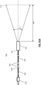
- the present invention provides a frontal light diffusing device 700 that satisfies these goals comprising an optical fiber 702 with a proximal connector 703, a distal termination 705, and a collimation lens assembly 704.
- the optical fiber 702 can be a cylindrical fiber, a non-circular core fiber (e.g., 302, 604), or a combination thereof discussed above.
- the collimation lens assembly 704 includes a collimation lens 706, which can be constructed of a transparent optical material, i.e. glass, crystal, a transparent polymer, or a reflective material.
- the collimation lens 706 can be comprised of a single optical element or a combination of optical elements.
- the collimation lens 706 can have any combination of spherical, aspherical, refractive, diffractive or reflective surfaces and the materials can have a graded index profile.
- the naturally divergent light output 708 of the fiber 702 is allowed to expand until it encounters the collimation lens 706.
- the fiber 702 is located so its output face 710 is approximately at the back focal length 712 of the collimation lens 706.
- a variable aperture 714 is located near or at the output of the collimation lens 704 where it can block portions of the light output 708, producing a light output beam 716 with extent that corresponds to the opening in 714. As shown in FIG.
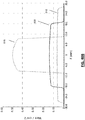
- collimated light output 716 has a "top hat" irradiance distribution as shown in FIG. 42B that is essentially the same magnitude (e.g., less +/- 20% difference in values, less than +/- 15% difference in values, or even +/- 10% difference in values) in (i) the near field (e.g. cross section 720 at a standoff distance of 724), (ii) the far field (e.g. cross section 722 at a standoff distance of 726), and the distance in between the near field and the far field, hereinafter defined as "flat irradiance distribution".
- the near field e.g. cross section 720 at a standoff distance of 724
- the far field e.g. cross section 722 at a standoff distance of 726
- the expanding cone of rays out of the fiber 702 is deliberately allowed to overfill the collimating lens 706.
- the solid line in the plot in FIG. 42B is the irradiance distribution measured at location 718 shown in FIG. 42A .
- the portions of the distribution with high variation are allowed to land on the structure of the collimation lens 704 and are blocked, reflected or absorbed. Only the uniform central portion of the irradiance distribution passes through both the collimation lens 706 and the variable aperture 714 to generate output beam 716, resulting in the flat irradiance distribution 720, shown as a dashed line in FIG. 42B .
- the aperture 714 located on the output side of the collimation lens 704 blocks portions of the light output 708 that are not desired.
- the aperture 714 is an iris that allows the beam size to be varied from 1 mm to 12 mm in diameter.
- the aperture 714 could be configured to produce a square, rectangular, or even a non-symmetric light output.
- the collimated light output 716 after the aperture 714 has very low divergence, so that the light output 718 is approximately the same size in the near field, at location 720 in FIG. 42A as it is in the far field, at location 722 in FIG. 42A .
- this resulting flat irradiance distributions at cross section 720 (shown as a dashed line) and cross section 722 (shown as a dash-dot line) have very close to flat top irradiance distribution and the beam size does not change significantly with distance (hereinafter defined as "flat irradiance distribution").
- the input fiber has a core diameter of 400 um and a clad diameter of 430 um and is filled with 1.01 Watts of 690 nm light having a numerical aperture of 0.29.
- the collimation lens 706 is comprised of a plano-convex lens with a 25 mm diameter and a focal length of 75 mm.
- the amount of excess optical power absorbed by the hand piece when generating a 12 mm diameter beam of 150 mWatt/cm 2 at 720 is less than 0.85 Watts, which is easily dissipated by the body of the hand piece. Referring to FIGS.
- the flat irradiance distribution at cross section 720 is measured at the standoff distance 724 of 100 mm from the aperture 714 and the flat irradiance distribution at cross section 722 is measured at the standoff distance 726 of 200 mm from the aperture 714.
- the performance of this embodiment 700 presents several advantageous characteristics.
- the size and geometry of the light output can be adjusted over a wide range without variation to the irradiance (mWatt/cm 2 ) at the target.
- the irradiance created on the target has very little dependence on the standoff distance between the projector and the target.
- a non-circular core fiber section e.g., 302, 606
- a wider output beam could be obtained.
- a non-circular core input fiber could be used.
- a cylindrical light diffusing device 400 is provided wherein it (400) is exactly the same as the cylindrical light diffusing device 100 discussed above except that it (400) has the non-circular core fiber 302 instead of the conventional circular optical fiber 12 of the device 100.
- the vertical (i.e., latitudinal) cross-sectional view of the non-circular core fiber 302 is the same as the embodiment shown on FIG. 14 .
- FIG. 32 shows the core irradiance distribution at the vertical cross-section (e.g., shown as "11" in FIG. 31 ) through the non-circular core fiber 302 taken just before the cylindrical diffuser 16.
- the associated irradiance distribution graphs shown in FIG. 32 taken from vertical and horizontal cross sections through the center of the map of the irradiance show the same "top hat" core irradiance distribution as the above-discussed conventional cylindrical light diffusing device 200, which requires a mode mixer (24).
- This "top hat” core irradiance distribution indicates a high degree of uniformity of the irradiance distribution in the fiber core 350.
- the device 400 cannot achieve the "top hat” diffusing irradiance distribution as shown in FIGS. 6 , 28 and 35 unless the construction of the cylindrical diffuser 16 is optimized to account for the launch conditions.
- the present invention includes the device 400 with such optimized cylindrical diffuser 16 in order to deliver the "top hat" diffusing irradiance distribution as shown in FIGS. 6 , 28 and 36 .
- a cylindrical light diffusing device is provided.
- This device has the same components as the device 400 discussed above in EXAMPLE I and shown in FIG. 31 except that the cylindrical diffuser 16 is now a conventional circular core optical fiber having a light emitting section containing internal scattering features 362 as shown in FIG. 33.
- FIG. 33 shows a vertical cross sectional view of this circular core fiber's 301 light emitting section having its cladding 352 and its circular fiber core 351, which contains internal scattering features 362.
- this device resulted in the diffusing irradiance distribution shown in FIG. 34 which provides a generally "top hat” diffusing irradiance distribution.
- the irradiance measurement of 150 mW/cm 2 is measured 0.75 mm from the central axis of the stated location of the light diffusing section.
- the diffusing irradiance distribution shown in FIG. 34 is closer to the optimal "top hat" diffusing irradiance distribution shown in FIG.
- top hat diffusing irradiance distribution shall include both the generally “top hat” diffusing irradiance distribution shown in FIG. 34 and the optimal "top hat” diffusing irradiance distribution shown in FIGS. 6 , 28 , and 36 .
- FIG. 34 shows that there is a potential for sub-optimal efficiency and efficacy when using internal scattering features 362 in a circular core optical fiber to create a light diffusing section intended to emit the desired "top hat" diffusing irradiance distribution because as the light propagates forward in the light emitting section, the irradiance in the optical axis of the optical fiber will gradually be depleted as the light encounters subsequent scattering features and leaves the light diffusing section. Since there is no mode mixing within this circular core light diffusing section, the vertical cross-sectional irradiance pattern will be less uniform, with the irradiance higher near the edges of the fiber core and depleted near the center where the scattering features are located.
- the present invention includes the cylindrical light diffusing device presented in this example and its generally “top hat” diffusing irradiance distribution because it is possible this device and its generally “top hat” diffusing irradiance distribution are sufficient for certain applications.
- the device 300 includes the non-circular core fiber 302, the lead-in optical fiber 304, the at least one optical connector 306.
- the lead-in optical fiber 304 is in light communication to (i) a light source (not shown) and (ii) the non-circular core fiber 302 via the at least one optical connector 306.
- the lead-in fiber 304 has a 200 ⁇ m OD glass core and a 230 ⁇ m OD cladding.
- the length of the non-circular core fiber 302 is 30 cm, which distally terminates into the light blocking means 314 made out of a reflecting coating of aluminum deposition.
- the non-circular core fiber 302 is filled with laser light having an angular distribution of a NA of 0.22.
- the fiber core 350 of the non-circular core fiber 302 is constructed out of PMMA with a hexagonal geometry in a circumscribed ⁇ 660 ⁇ m diameter circle.
- the fiber core 350 is cladded by the cladding 352 with an interior surface geometry 356 that has the same hexagonal geometry as the fiber core 350.
- the exterior surface geometry 354 of the cladding 352 is circular.
- the cladding 352 is constructed of a silicone with a ⁇ 740 ⁇ m OD.
- the non-circular core fiber 302 further includes the light diffusing section 308 having the diffusing proximal end 310 and the diffusing distal end 312.
- the light diffusing section 308 is 10.8 mm in longitudinal length and the internal scattering features 362 begin at the diffusing proximal end 310 and ends at the diffusing distal end 312.
- the features 362 are comprised of 27 sets of three cylinders. Each cylinder is approximately 27 ⁇ m in diameter and 270 ⁇ m in length oriented around the central axis 364 at 60° increments as shown in FIGS. 9 and 10 .
- the present invention is not limited to this formula, the size of the features 362, the number of features 362 per unit length of the diffusing section 308, or the amount of scattering per feature 362.
- the present invention includes other suitable spacing's, sizes, numbers of features 362 per unit length, and amounts of scattering per feature 362.
- the following characteristics of the device 300 may be adjusted in order to further optimize its diffusing irradiance distribution: the longitudinal length and diameter of the diffusing section 308, the size and geometry of the fiber core 350 and any cladding 352, the scattering characteristics of the features 362, the maximum angle coming out the of the light source and/or the lead-in fiber 304, and the inclusion of the light blocking means 314 at the distal end of the non-circular core fiber 302.
- This optimization can be performed experimentally or using a ray tracing CAD program.
- the common factor in determining an optimal diffusing irradiance distribution is to engineer a linear increase in the effective scattering per incremental volume, as there is a linear decrease in the light density per incremental volume in the fiber core 350.
- FIG. 27 shows a map of the irradiance at the vertical cross-section (shown as "316" in FIG. 9 ) through the fiber core 350 taken just before the diffusing proximal end 310 for this exemplary embodiment of the device 300.
- the light source used is a 690 nm laser with 0.125 Watt launch power and this power was adjusted until the irradiance measured at the center 307 of the longitudinal length of the light diffusing section 308 was 150 mW/cm 2 . This measurement is taken 0.75 mm from the central axis of the stated location of the light diffusing section 308.
- the total length of optical fiber (combination of the lead-in fiber 304 and the non-circular core fiber 302) from the light source leading up to this location 316 is 2 meters long.
- the non-circular core fiber 302 is filled with laser light having an angular distribution of a NA of 0.22.
- the associated irradiance distribution graphs shown in FIG. 27 taken from vertical and horizontal cross sections through the center of the map of the irradiance show the same "top hat" core irradiance distribution as the above-discussed conventional cylindrical light diffusing device 200 containing a mode mixer 24.
- This "top hat" core irradiance distribution indicates a high degree of uniformity of the irradiance distribution in the fiber core 350 (e.g. optimal core irradiance distribution).
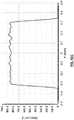
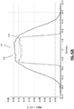
- FIG. 28 shows the out-coupled longitudinally radially-symmetric irradiance distribution along the outer surface of the light diffusing section 308 (e.g., the diffusing irradiance distribution) of this exemplary embodiment of the device 300.
- the diffusing irradiance distribution shows the optimal "top hat" irradiance distribution indicating spatial uniformity of the out-coupled longitudinally radially-symmetric irradiance along the outer surface of the light diffusing section 308.
- the horizontal axis of FIG. 28 shows longitudinal length in mm and the horizontal arrow indicates the longitudinal length of the light diffusing section 308.
- the vertical axis of FIG. 28 shows the out-coupled irradiance at the surface of the light diffusing section 308 measured in Watts/cm 2 at a distance 0.75 mm from the central axis.
- the device 300 includes the non-circular core fiber 302, the lead-in optical fiber 304, the at least one optical connector 306.
- the lead-in optical fiber 304 is in light communication to (i) a light source (not shown) and (ii) the non-circular core fiber 302 via the at least one optical connector 306.
- the lead-in fiber 304 has a 200 ⁇ m OD glass core and a 230 ⁇ m OD cladding.
- the length of the non-circular core fiber 302 is 30 cm, which distally terminates into the light blocking means 314 made out of a reflecting coating of aluminum deposition.
- the non-circular core fiber 302 includes the fiber core 350 constructed out of PMMA with a hexagonal geometry in a circumscribed ⁇ 660 ⁇ m diameter circle.
- the fiber core 350 is cladded by the cladding 352 with an interior surface geometry 356 that is same hexagonal geometry as the fiber core 350.
- the exterior surface geometry 354 of the cladding 352 is circular.
- the cladding 352 is constructed of a polymer with a ⁇ 740 ⁇ m OD.
- the non-circular core fiber 302 further includes the enclosed open cavity 358 and the covering 360.
- the covering 360 is constructed of a translucent Pebax® resin with a ⁇ 1000 ⁇ m OD and a ⁇ 900 ⁇ m ID. The covering is heat sealed at one or both of its ends.
- the non-circular core fiber 302 further includes the light diffusing section 308 having the diffusing proximal end 310 and the diffusing distal end 312.
- the light diffusing section 308 is exactly the same as the light diffusing section 308 of the embodiment described above in Example III including its internal scattering features 362.
- FIG. 35 shows a map of the irradiance at the vertical cross-section (shown as "316" in FIG. 11 ) through the fiber core 350 taken just before the diffusing proximal end 310 for this exemplary embodiment of the device 300.
- the light source used is a 690 nm laser with 0.125 Watt launch power and this power was adjusted until the irradiance measured until the irradiance measured at the center 307 of the longitudinal length of the light diffusing section 308 was 150 mW/cm 2 . This measurement is taken 0.75 mm from the central axis of the stated location of the light diffusion section 308.
- the total length of optical fiber (combination of the lead-in fiber 304 and the non-circular core fiber 302) from the light source leading up to this location 316 is 2 meters long.
- the non-circular core fiber 302 is filled with laser light having an angular distribution of a NA of 0.22.
- the associated irradiance distribution graphs shown in FIG. 35 taken from vertical and horizontal cross sections through the center of the map of the irradiance show the same "top hat" core irradiance distribution as the above-discussed conventional cylindrical light diffusing device 200 with a mode mixer (24).
- This "top hat" core irradiance distribution indicates a high degree of uniformity of the irradiance distribution in the fiber core 350.
- FIG. 36 shows the out-coupled longitudinally radially-symmetric irradiance distribution along the outer surface of the light diffusing section 308 (e.g., the diffusing irradiance distribution) of this exemplary embodiment of the device 300.
- the diffusing irradiance distribution shows the optimal "top hat" irradiance distribution indicating spatial uniformity of the out-coupled longitudinally radially-symmetric irradiance along the outer surface of the light diffusing section 308.
- the horizontal axis of FIG. 36 shows longitudinal length in mm and the horizontal arrow indicates the longitudinal length of the light diffusing section 308.
- the vertical axis of FIG. 36 shows the out-coupled irradiance at the surface of the light diffusing section 308 measured in Watts/cm 2 at a distance 0.75 mm from the central axis.
- the device 300 includes the non-circular core fiber 302, the lead-in optical fiber 304, the at least one optical connector 306.
- the lead-in optical fiber 304 is in light communication to (i) a light source (not shown) and (ii) the non-circular core fiber 302 via the at least one optical connector 306.
- the lead-in fiber 304 has a 200 ⁇ m OD glass core and a 230 ⁇ m OD cladding.
- the length of the non-circular core fiber 302 is 30 cm, which distally terminates into the light blocking means 314 made out of a reflecting coating of aluminum deposition.
- the non-circular core fiber 302 includes the fiber core 350 constructed out of glass with a hexagonal geometry in a circumscribed ⁇ 460 ⁇ m diameter circle.
- the fiber core 350 is cladded by the cladding 352 with an interior surface geometry 356 that is same hexagonal geometry as the fiber core 350.
- the exterior surface geometry 354 of the cladding 352 is circular.
- the cladding 352 is constructed of a glass with a ⁇ 480 ⁇ m OD.
- the non-circular core fiber 302 further includes the enclosed open cavity 358 and the covering 360.
- the covering 360 is constructed of a translucent Pebax® resin with a ⁇ 1000 ⁇ m OD and a ⁇ 800 ⁇ m ID. The covering is heat sealed at one or both of its ends.
- the non-circular core fiber 302 further includes the light diffusing section 308 having the diffusing proximal end 310 and the diffusing distal end 312.
- the light diffusing section 308 is 11.3 mm in longitudinal length and the internal scattering features 362 begin at the diffusing proximal end 310 and ends at the diffusing distal end 312.
- the features 362 are comprised of 37 sets of 6 ellipses. Each ellipse is approximately spherical with a 40 ⁇ m diameter and is located 100 um from the central axis of the fiber core 350 and distributed at 60° increments as shown in FIG. 43 .
- the present invention is not limited to this formula, the size of the features 362, the number of features 362 per unit length of the diffusing section 308, or the amount of scattering per feature 362.
- the present invention includes other suitable spacing's, sizes, numbers of features 362 per unit length, and amounts of scattering per feature 362.
- the light source and the total length are exactly the same as the embodiment described above in Example IV and the map of the irradiance at the vertical cross-section 316 has values that are within +/- 10% to that shown in FIG. 35 .
- the diffusing irradiance distribution shows an optimal "top hat" irradiance distribution that has values that are within +/- 20% as shown in FIG. 36 .
- the present invention provides a frontal light diffusing device 600 includes a fiber optic connector 603, a cylindrical fiber section 602, a non-circular core fiber 604, a pair of optical connectors 605, and a lens component 606.
- the cylindrical fiber section 602 is in light communication to (i) a light source (not shown) via fiber optic connector 603 and (ii) the non-circular core fiber section 604 is also in light communication with the lens component 606.
- the fiber optic connector 603 is SMA style and the cylindrical fiber section 602 has a 200 ⁇ m OD glass core and a 220 ⁇ m OD cladding and a 700 um OD Tefzel jacket.
- the pair of fiber optical connectors 605 are SMA style and the non-circular core fiber 604 has a hexagonal glass core with a circumscribed 460 um diameter and a cylindrical glass core with a 480 um external diameter and is covered by a 1.05 mm diameter Tefzel jacket.
- the lens component 606 is a 0.5 NA, 1 ⁇ 4 pitch GRIN lens with a 0.8 mm OD that is affixed to the distal end of the non-circular core fiber 604 with an optical epoxy.
- the length of the non-circular core fiber is 30 cm and the combined length of the frontal light diffusing device 600 is 2 meters.
- the light source used is a 690 nm laser that couples 2.2 Watts of 0.22 NA launch power into the lead in fiber 602 and this power is adjusted until the irradiance measured at the target 614 with a stand-off 616 of 80 mm is 150 mW/cm 2 with a top hat distribution with a 40 mm internal diameter that has values that are within +/-10% of the FIG 41D .
- the method of the present invention further includes applying a photosensitive drug composition to desired treatment site; placing the device (300, 400) described interstitially inside the desired treatment site and applying light delivered by the device 300 to the treatment site at a wavelength absorbed by the photosensitive drug composition so as to inhibit targeted cells located within the treatment site.
Landscapes
- Physics & Mathematics (AREA)
- Optics & Photonics (AREA)
- Health & Medical Sciences (AREA)
- General Physics & Mathematics (AREA)
- Engineering & Computer Science (AREA)
- Biomedical Technology (AREA)
- Life Sciences & Earth Sciences (AREA)
- Animal Behavior & Ethology (AREA)
- Radiology & Medical Imaging (AREA)
- Nuclear Medicine, Radiotherapy & Molecular Imaging (AREA)
- Pathology (AREA)
- General Health & Medical Sciences (AREA)
- Public Health (AREA)
- Veterinary Medicine (AREA)
- Biophysics (AREA)
- Astronomy & Astrophysics (AREA)
- Light Guides In General And Applications Therefor (AREA)
- Optical Fibers, Optical Fiber Cores, And Optical Fiber Bundles (AREA)
- Optical Couplings Of Light Guides (AREA)
- Radiation-Therapy Devices (AREA)
- Artificial Filaments (AREA)
- Absorbent Articles And Supports Therefor (AREA)
Applications Claiming Priority (4)
| Application Number | Priority Date | Filing Date | Title |
|---|---|---|---|
| US201662412606P | 2016-10-25 | 2016-10-25 | |
| US201762529507P | 2017-07-07 | 2017-07-07 | |
| PCT/US2017/057787 WO2018080952A1 (en) | 2016-10-25 | 2017-10-23 | Light diffusing devices for use in photoimmunotherapy |
| EP17804677.7A EP3532771A1 (de) | 2016-10-25 | 2017-10-23 | Lichtstreuvorrichtungen zur verwendung in der photoimmuntherapie |
Related Parent Applications (1)
| Application Number | Title | Priority Date | Filing Date |
|---|---|---|---|
| EP17804677.7A Division EP3532771A1 (de) | 2016-10-25 | 2017-10-23 | Lichtstreuvorrichtungen zur verwendung in der photoimmuntherapie |
Publications (1)
| Publication Number | Publication Date |
|---|---|
| EP3663816A1 true EP3663816A1 (de) | 2020-06-10 |
Family
ID=60473584
Family Applications (2)
| Application Number | Title | Priority Date | Filing Date |
|---|---|---|---|
| EP19214413.7A Withdrawn EP3663816A1 (de) | 2016-10-25 | 2017-10-23 | Lichtstreuvorrichtungen zur verwendung in der photoimmuntherapie |
| EP17804677.7A Withdrawn EP3532771A1 (de) | 2016-10-25 | 2017-10-23 | Lichtstreuvorrichtungen zur verwendung in der photoimmuntherapie |
Family Applications After (1)
| Application Number | Title | Priority Date | Filing Date |
|---|---|---|---|
| EP17804677.7A Withdrawn EP3532771A1 (de) | 2016-10-25 | 2017-10-23 | Lichtstreuvorrichtungen zur verwendung in der photoimmuntherapie |
Country Status (12)
| Country | Link |
|---|---|
| US (3) | US10527771B2 (de) |
| EP (2) | EP3663816A1 (de) |
| JP (3) | JP6688940B2 (de) |
| KR (3) | KR20200038336A (de) |
| CN (2) | CN111035858B (de) |
| AU (3) | AU2017351052B2 (de) |
| BR (2) | BR122020013058B1 (de) |
| CA (3) | CA3070469C (de) |
| MX (3) | MX376819B (de) |
| RU (2) | RU2741076C2 (de) |
| SG (2) | SG11201903062TA (de) |
| WO (1) | WO2018080952A1 (de) |
Families Citing this family (32)
| Publication number | Priority date | Publication date | Assignee | Title |
|---|---|---|---|---|
| US8524239B2 (en) | 2010-07-09 | 2013-09-03 | The United States of America as represented by the Secrectary, Department of Health and Human Services | Photosensitizing antibody-fluorophore conjugates |
| US10830678B2 (en) | 2014-08-08 | 2020-11-10 | The United States Of America, As Represented By The Secretary, Department Of Health And Human Serv | Photo-controlled removal of targets in vitro and in vivo |
| CN121270700A (zh) | 2015-08-07 | 2026-01-06 | 美国政府(由卫生和人类服务部的部长所代表) | 用于治疗癌症的针对抑制细胞的近红外光免疫疗法(nir-pit) |
| ES2889904T3 (es) | 2015-08-18 | 2022-01-14 | Rakuten Medical Inc | Conjugados de colorante de ftalocianina y su almacenamiento |
| US11154620B2 (en) | 2015-08-18 | 2021-10-26 | Rakuten Medical, Inc. | Compositions, combinations and related methods for photoimmunotherapy |
| CA3070469C (en) * | 2016-10-25 | 2022-06-21 | Rakuten Medical, Inc. | Light diffusing devices for use in photoimmunotherapy |
| US11007011B2 (en) * | 2017-11-10 | 2021-05-18 | Boston Scientific Scimed, Inc. | Medical laser fiber |
| SG11202011538RA (en) | 2018-06-01 | 2020-12-30 | Rakuten Medical Inc | Phthalocyanine dye conjugate compositions |
| JP2022065214A (ja) | 2019-02-28 | 2022-04-27 | テルモ株式会社 | 治療方法および治療システム |
| CN114423453A (zh) | 2019-07-30 | 2022-04-29 | 乐天医药生技股份有限公司 | 使用偶联的抗cd25酞菁和抗pd1的基于光化学的癌症疗法近红外(nir)光免疫疗法(pit) |
| JP7406773B2 (ja) * | 2019-08-30 | 2023-12-28 | タツタ電線株式会社 | 光ファイバ |
| DE102019123448B4 (de) | 2019-09-02 | 2024-01-25 | Schott Ag | Beleuchtungssystem mit einem Lichtleiter und einem Abstrahlelement |
| JP2022546546A (ja) | 2019-09-03 | 2022-11-04 | ラクテン・メディカル,インコーポレイテッド | フタロシアニン色素-ターゲティング分子コンジュゲートを使用する処置のための方法 |
| JPWO2021066012A1 (de) * | 2019-09-30 | 2021-04-08 | ||
| CN115052631A (zh) | 2019-12-06 | 2022-09-13 | 乐天医药生技股份有限公司 | 用于增强免疫及肿瘤治疗的方法 |
| CN113017825A (zh) * | 2019-12-31 | 2021-06-25 | 华科精准(北京)医疗科技有限公司 | 用于激光间质热疗系统的装置 |
| WO2021207691A1 (en) | 2020-04-10 | 2021-10-14 | Rakuten Medical, Inc. | Phthalocyanine dye compounds, conjugates and methods of use thereof |
| EP4160282A4 (de) * | 2020-07-09 | 2024-07-24 | Toray Industries, Inc. | Kunststofflichtfaser, medizinische beleuchtungsvorrichtung, medizinische sensorvorrichtung, medizinische lichttherapeutische vorrichtung und kunststofflichtfaserkabel |
| JP2024505556A (ja) | 2021-02-02 | 2024-02-06 | ラクテン・メディカル,インコーポレイテッド | がん、腫瘍および腫瘍細胞の局所および全身処置のための方法 |
| EP4316339A4 (de) * | 2021-03-30 | 2024-12-18 | Furukawa Electric Co., Ltd. | Strahlungssondensystem und strahlungssonde |
| EP4324120B1 (de) * | 2021-04-13 | 2025-06-11 | Signify Holding B.V. | Optischer detektor |
| US12311195B2 (en) * | 2021-08-03 | 2025-05-27 | Modulight Corporation | Theranostic laser system |
| KR20240056517A (ko) * | 2021-09-17 | 2024-04-30 | 일렉트로 싸이언티픽 인더스트리이즈 인코포레이티드 | 광검출기 상의 레이저 빔의 위치 감도 감소를 위한 컨디셔닝 장치 및 이를 사용하는 방법 |
| DE112022005743T5 (de) * | 2021-12-02 | 2024-09-26 | Furukawa Electric Co., Ltd. | Lichtstreuungsvorrichtung |
| IL289646A (en) * | 2022-01-05 | 2023-08-01 | Steba Biotech S A | System and method for photodynamic therapy |
| AU2023221861A1 (en) | 2022-02-18 | 2024-09-05 | Rakuten Medical, Inc. | Anti-programmed death-ligand 1 (pd-l1) antibody molecules, encoding polynucleotides, and methods of use |
| CN114569749A (zh) * | 2022-03-01 | 2022-06-03 | 广东国志激光技术有限公司 | 一种医用介入式导管的激光消毒杀菌装置 |
| CN114527534B (zh) * | 2022-04-24 | 2022-06-24 | 武汉锐科光纤激光技术股份有限公司 | 光纤剥模器、光纤剥模器制备方法及激光设备 |
| CN114966950A (zh) * | 2022-04-25 | 2022-08-30 | 深圳市雷迈科技有限公司 | 一种医用柱状光纤及其制备方法 |
| EP4390218B1 (de) | 2022-12-23 | 2026-04-08 | biolitec Holding GmbH & Co KG | Starke, ermüdungsbeständige optische faser mit verbesserter seitenbestrahlung |
| US20240280735A1 (en) * | 2023-02-22 | 2024-08-22 | Rayotek Scientific, Inc. | Optical diffuser to improve photon capture for improved photochemical reactions |
| CN119587898B (zh) * | 2025-01-03 | 2025-10-14 | 陕西朔光启复医疗科技有限公司 | 一种柱状匀光激光光纤 |
Citations (6)
| Publication number | Priority date | Publication date | Assignee | Title |
|---|---|---|---|---|
| JPS59137069A (ja) * | 1983-01-27 | 1984-08-06 | 株式会社東芝 | レ−ザ治療装置 |
| US20070147758A1 (en) * | 2005-09-26 | 2007-06-28 | Edmund Optics, Inc. | Light integrator with circular light output |
| WO2010019800A1 (en) * | 2008-08-13 | 2010-02-18 | Nomir Medical Technologies, Inc. | Therapeutic light delivery apparatus, method, and system |
| US8831396B1 (en) * | 2011-10-31 | 2014-09-09 | Nlight Photonics Corporation | Homogenizing optical fiber apparatus and systems employing the same |
| JP2015009031A (ja) * | 2013-07-01 | 2015-01-19 | 飛鳥メディカル株式会社 | レーザー治療器 |
| US20160106504A1 (en) * | 2014-10-08 | 2016-04-21 | Bios S.R.L. | Laser device for dermocosmetic treatments and tracing kit |
Family Cites Families (47)
| Publication number | Priority date | Publication date | Assignee | Title |
|---|---|---|---|---|
| JPS59216164A (ja) * | 1983-05-24 | 1984-12-06 | Canon Inc | 光源装置 |
| US5207673A (en) * | 1989-06-09 | 1993-05-04 | Premier Laser Systems, Inc. | Fiber optic apparatus for use with medical lasers |
| US6270492B1 (en) * | 1994-09-09 | 2001-08-07 | Cardiofocus, Inc. | Phototherapeutic apparatus with diffusive tip assembly |
| EP0781154A2 (de) * | 1994-09-09 | 1997-07-02 | Rare Earth Medical, Inc. | Phototherapeutische vorrichtung |
| JPH09258028A (ja) * | 1996-03-26 | 1997-10-03 | Toray Ind Inc | 側面漏光プラスチック光ファイバ |
| US5978541A (en) | 1996-04-16 | 1999-11-02 | Miravant Systems, Inc. | Custom cylindrical diffusion tips |
| US5751869A (en) * | 1996-08-08 | 1998-05-12 | Cogent Light Technologies, Inc. | Optical system for coupling light from a single fiber optic into a fiber bundle |
| DE19739456B4 (de) * | 1997-09-03 | 2008-01-03 | Trumpf Medizin Systeme Gmbh + Co. Kg | Applikationsvorrichtung für die Behandlung von Körpergewebe mittels Licht |
| WO1999023041A1 (en) * | 1997-10-30 | 1999-05-14 | Miravant Systems, Inc. | Fiber optic diffuser and method of manufacture |
| CA2375267A1 (en) * | 1999-06-18 | 2000-12-28 | Xijia Gu | Optical fiber diffuser |
| US6366719B1 (en) * | 2000-08-17 | 2002-04-02 | Miravant Systems, Inc. | Photodynamic therapy light diffuser |
| US6735367B2 (en) * | 2001-12-28 | 2004-05-11 | David W. Sanso | Illumination light conducting optical-fiber configuration for endoscope cable |
| JP2006507016A (ja) * | 2002-02-05 | 2006-03-02 | ファーマサイクリックス・インコーポレーテッド | 円錐形拡散システムを使用する光送出デバイス、およびその形成方法 |
| US6845193B2 (en) * | 2002-05-21 | 2005-01-18 | Trimedyne, Inc. | Laser channeling devices |
| AU2003298561A1 (en) * | 2002-08-23 | 2004-05-13 | Jonathan S. Dahm | Method and apparatus for using light emitting diodes |
| US8983257B2 (en) * | 2002-08-28 | 2015-03-17 | Nomir Medical Technologies, Inc. | Therapeutic light delivery apparatus, method, and system |
| US20040151008A1 (en) * | 2003-02-03 | 2004-08-05 | Artsyukhovich Alexander N. | Variable spot size illuminators with enhanced homogeneity and parfocality |
| JP2005056608A (ja) | 2003-08-06 | 2005-03-03 | Tokyo Iken Kk | 光照射装置及びこの光照射装置を使用する光線治療器 |
| JP2005087531A (ja) | 2003-09-18 | 2005-04-07 | Seikoh Giken Co Ltd | レーザプローブ |
| JP4559149B2 (ja) | 2004-07-23 | 2010-10-06 | オリンパス株式会社 | 照明光学系、照明光学系を用いた照明装置、及び照明光学系又は照明光学系を用いた照明装置を用いた観察システム |
| US7758224B2 (en) | 2004-10-01 | 2010-07-20 | Nichia Corporation | Light emitting device |
| US7167630B2 (en) * | 2004-11-08 | 2007-01-23 | Kodak Il, Ltd. | Beam shaper and imaging head having beam shapers |
| US7274847B2 (en) * | 2004-11-16 | 2007-09-25 | Biotex, Inc. | Light diffusing tip |
| JP2007102058A (ja) | 2005-10-07 | 2007-04-19 | Kinichi Ogawa | レーザ光の導光構造 |
| US7474820B2 (en) | 2006-04-27 | 2009-01-06 | Invuity, Inc. | Micro-optic adapters and tips for surgical illumination fibers |
| WO2008024397A2 (en) | 2006-08-24 | 2008-02-28 | Ceramoptec Industries, Inc | Medical light diffusers for high power applications and their manufacture |
| DE102006046925A1 (de) | 2006-09-28 | 2008-04-03 | Jenlab Gmbh | Verfahren und Anordnung zur Laser-Endoskopie für die Mikrobearbeitung |
| TWI326773B (en) * | 2006-12-29 | 2010-07-01 | Ind Tech Res Inst | Improved optical fiber and the manufacturing method thereof |
| EP2150194B1 (de) * | 2007-04-27 | 2012-09-12 | Tyco Healthcare Group LP | System zur behandlung hohler anatomischer strukturen |
| JP2009168914A (ja) | 2008-01-11 | 2009-07-30 | Mitsubishi Cable Ind Ltd | 光ファイバ及びその製造方法 |
| US7862219B2 (en) * | 2008-10-22 | 2011-01-04 | Advanced Photodynamic Technologies, Inc. | Optical fiber light diffusing device |
| EP2624777B1 (de) * | 2010-10-07 | 2019-03-20 | Gradiant Research, Llc | Vorrichtung für eine hautkrebs-wärmetherapie |
| US8620125B2 (en) * | 2011-04-29 | 2013-12-31 | Corning Incorporated | Light diffusing fibers and methods for making the same |
| US8805141B2 (en) * | 2011-10-07 | 2014-08-12 | Corning Incorporated | Optical fiber illumination systems and methods |
| US9250390B2 (en) | 2011-12-09 | 2016-02-02 | Lumentum Operations Llc | Varying beam parameter product of a laser beam |
| DE102011122209A1 (de) * | 2011-12-23 | 2013-06-27 | Carl Zeiss Meditec Ag | Vorrichtung zur Homogenisierung eines Laserstrahlprofils |
| JP5612028B2 (ja) * | 2012-07-02 | 2014-10-22 | 富士フイルム株式会社 | 光源装置及び内視鏡システム |
| JP5882864B2 (ja) * | 2012-09-13 | 2016-03-09 | スガ試験機株式会社 | 拡散ヘーズ値測定方法及び測定装置 |
| JP6161693B2 (ja) * | 2013-05-08 | 2017-07-12 | 株式会社島津製作所 | 蛍光測定装置及び蛍光測定方法 |
| JP6282554B2 (ja) | 2014-07-28 | 2018-02-21 | 飛鳥メディカル株式会社 | レーザー治療器 |
| JP6034344B2 (ja) | 2014-08-29 | 2016-11-30 | 株式会社フジクラ | 光ファイバケーブル |
| JP2016067492A (ja) | 2014-09-29 | 2016-05-09 | Meiji Seikaファルマ株式会社 | 光照射器および子宮頚部用光線力学的治療装置 |
| JP2016078043A (ja) | 2014-10-14 | 2016-05-16 | 株式会社アマダホールディングス | レーザ加工機 |
| RU2571322C1 (ru) * | 2014-11-13 | 2015-12-20 | Вячеслав Григорьевич Артюшенко | Устройство для облучения сосудов и полых органов |
| WO2016137933A1 (en) * | 2015-02-23 | 2016-09-01 | Soundcore Technology, Llc. | Medical tool with image enhancing features |
| DE102015119875A1 (de) * | 2015-06-19 | 2016-12-22 | Laser- Und Medizin-Technologie Gmbh, Berlin | Lateral abstrahlende Lichtwellenleiter und Verfahren zur Einbringung von Mikromodifikationen in einen Lichtwellenleiter |
| CA3070469C (en) * | 2016-10-25 | 2022-06-21 | Rakuten Medical, Inc. | Light diffusing devices for use in photoimmunotherapy |
-
2017
- 2017-10-23 CA CA3070469A patent/CA3070469C/en active Active
- 2017-10-23 KR KR1020207009761A patent/KR20200038336A/ko not_active Ceased
- 2017-10-23 CN CN201911310538.1A patent/CN111035858B/zh not_active Expired - Fee Related
- 2017-10-23 WO PCT/US2017/057787 patent/WO2018080952A1/en not_active Ceased
- 2017-10-23 EP EP19214413.7A patent/EP3663816A1/de not_active Withdrawn
- 2017-10-23 MX MX2019015283A patent/MX376819B/es active IP Right Grant
- 2017-10-23 RU RU2019112596A patent/RU2741076C2/ru active
- 2017-10-23 BR BR122020013058-0A patent/BR122020013058B1/pt active IP Right Grant
- 2017-10-23 RU RU2019140000A patent/RU2740793C2/ru active
- 2017-10-23 US US15/790,110 patent/US10527771B2/en active Active
- 2017-10-23 KR KR1020197011851A patent/KR102103127B1/ko not_active Expired - Fee Related
- 2017-10-23 SG SG11201903062TA patent/SG11201903062TA/en unknown
- 2017-10-23 KR KR1020207006249A patent/KR102132145B1/ko active Active
- 2017-10-23 CN CN201780065396.XA patent/CN109863346A/zh active Pending
- 2017-10-23 US US15/790,113 patent/US10295719B2/en active Active
- 2017-10-23 BR BR112019008189A patent/BR112019008189A2/pt not_active Application Discontinuation
- 2017-10-23 MX MX2019015282A patent/MX376820B/es active IP Right Grant
- 2017-10-23 EP EP17804677.7A patent/EP3532771A1/de not_active Withdrawn
- 2017-10-23 AU AU2017351052A patent/AU2017351052B2/en not_active Ceased
- 2017-10-23 MX MX2019004391A patent/MX371235B/es active IP Right Grant
- 2017-10-23 CA CA3042568A patent/CA3042568C/en not_active Expired - Fee Related
- 2017-10-23 SG SG10201910800SA patent/SG10201910800SA/en unknown
- 2017-10-23 JP JP2019521686A patent/JP6688940B2/ja active Active
-
2018
- 2018-04-24 CA CA3066354A patent/CA3066354A1/en not_active Abandoned
-
2019
- 2019-09-03 AU AU2019226155A patent/AU2019226155B2/en not_active Ceased
- 2019-12-03 US US16/701,394 patent/US10908341B2/en active Active
-
2020
- 2020-01-17 JP JP2020005702A patent/JP6829780B2/ja active Active
- 2020-04-06 JP JP2020068054A patent/JP2020114467A/ja active Pending
- 2020-06-22 AU AU2020204136A patent/AU2020204136B2/en not_active Ceased
Patent Citations (6)
| Publication number | Priority date | Publication date | Assignee | Title |
|---|---|---|---|---|
| JPS59137069A (ja) * | 1983-01-27 | 1984-08-06 | 株式会社東芝 | レ−ザ治療装置 |
| US20070147758A1 (en) * | 2005-09-26 | 2007-06-28 | Edmund Optics, Inc. | Light integrator with circular light output |
| WO2010019800A1 (en) * | 2008-08-13 | 2010-02-18 | Nomir Medical Technologies, Inc. | Therapeutic light delivery apparatus, method, and system |
| US8831396B1 (en) * | 2011-10-31 | 2014-09-09 | Nlight Photonics Corporation | Homogenizing optical fiber apparatus and systems employing the same |
| JP2015009031A (ja) * | 2013-07-01 | 2015-01-19 | 飛鳥メディカル株式会社 | レーザー治療器 |
| US20160106504A1 (en) * | 2014-10-08 | 2016-04-21 | Bios S.R.L. | Laser device for dermocosmetic treatments and tracing kit |
Non-Patent Citations (4)
| Title |
|---|
| BOLESH J. SKUTNIK: "Non-circular core, all silica fibers for irradiation and sensing medical applications", PROCEEDINGS OPTICAL DIAGNOSTICS OF LIVING CELLS II, vol. 8576, 20 March 2013 (2013-03-20), US, pages 85760J, XP055437943, ISSN: 0277-786X, ISBN: 978-1-5106-1324-9, DOI: 10.1117/12.2004985 * |
| CHANCLOU P ET AL: "Design and demonstration of a multicore single-mode fiber coupled lens device", OPTICS COMMUNICATIONS, ELSEVIER, AMSTERDAM, NL, vol. 233, no. 4-6, 1 April 2004 (2004-04-01), pages 333 - 339, XP004495395, ISSN: 0030-4018, DOI: 10.1016/J.OPTCOM.2004.01.052 * |
| GRINTECH GMBH: "Gradient Index (GRIN) Lenses", 1 December 2015 (2015-12-01), XP055830340, Retrieved from the Internet <URL:https://www.grintech.de/fileadmin/user_upload/Introduction_GRIN_Lenses.pdf> [retrieved on 20210805] * |
| MARTIN VAN BUREN ET AL: "Foundations for low-loss fiber gradient-index lens pair coupling with the self-imaging mechanism", APPLIED OPTICS, vol. 42, no. 3, 20 January 2003 (2003-01-20), US, pages 550, XP055486666, ISSN: 0003-6935, DOI: 10.1364/AO.42.000550 * |
Also Published As
Similar Documents
| Publication | Publication Date | Title |
|---|---|---|
| AU2020204136B2 (en) | Light diffusing devices for use in photoimmunotherapy | |
| US10416366B2 (en) | Light diffusing devices for use in photoimmunotherapy | |
| EP3635458B1 (de) | Lichtdiffusionsvorrichtungen zur verwendung in der fotoimmuntherapie | |
| NZ764323B2 (en) | Light diffusing devices for use in photoimmunotherapy | |
| NZ760765B2 (en) | Light diffusing devices for use in photoimmunotherapy | |
| HK40017629B (en) | Frontal light diffusing device for photoimmunotherapy | |
| HK40017629A (en) | Frontal light diffusing device for photoimmunotherapy |
Legal Events
| Date | Code | Title | Description |
|---|---|---|---|
| PUAI | Public reference made under article 153(3) epc to a published international application that has entered the european phase |
Free format text: ORIGINAL CODE: 0009012 |
|
| STAA | Information on the status of an ep patent application or granted ep patent |
Free format text: STATUS: THE APPLICATION HAS BEEN PUBLISHED |
|
| AC | Divisional application: reference to earlier application |
Ref document number: 3532771 Country of ref document: EP Kind code of ref document: P |
|
| AK | Designated contracting states |
Kind code of ref document: A1 Designated state(s): AL AT BE BG CH CY CZ DE DK EE ES FI FR GB GR HR HU IE IS IT LI LT LU LV MC MK MT NL NO PL PT RO RS SE SI SK SM TR |
|
| AX | Request for extension of the european patent |
Extension state: BA ME |
|
| STAA | Information on the status of an ep patent application or granted ep patent |
Free format text: STATUS: REQUEST FOR EXAMINATION WAS MADE |
|
| 17P | Request for examination filed |
Effective date: 20200713 |
|
| RBV | Designated contracting states (corrected) |
Designated state(s): AL AT BE BG CH CY CZ DE DK EE ES FI FR GB GR HR HU IE IS IT LI LT LU LV MC MK MT NL NO PL PT RO RS SE SI SK SM TR |
|
| STAA | Information on the status of an ep patent application or granted ep patent |
Free format text: STATUS: EXAMINATION IS IN PROGRESS |
|
| 17Q | First examination report despatched |
Effective date: 20201005 |
|
| STAA | Information on the status of an ep patent application or granted ep patent |
Free format text: STATUS: THE APPLICATION HAS BEEN WITHDRAWN |
|
| 18W | Application withdrawn |
Effective date: 20230321 |