EP3663827A1 - Afficheur tête haute - Google Patents
Afficheur tête haute Download PDFInfo
- Publication number
- EP3663827A1 EP3663827A1 EP18209752.7A EP18209752A EP3663827A1 EP 3663827 A1 EP3663827 A1 EP 3663827A1 EP 18209752 A EP18209752 A EP 18209752A EP 3663827 A1 EP3663827 A1 EP 3663827A1
- Authority
- EP
- European Patent Office
- Prior art keywords
- screen
- display
- heat sink
- base
- housing
- Prior art date
- Legal status (The legal status is an assumption and is not a legal conclusion. Google has not performed a legal analysis and makes no representation as to the accuracy of the status listed.)
- Pending
Links
Images
Classifications
-
- G—PHYSICS
- G02—OPTICS
- G02B—OPTICAL ELEMENTS, SYSTEMS OR APPARATUS
- G02B27/00—Optical systems or apparatus not provided for by any of the groups G02B1/00 - G02B26/00, G02B30/00
- G02B27/01—Head-up displays
- G02B27/0149—Head-up displays characterised by mechanical features
-
- B—PERFORMING OPERATIONS; TRANSPORTING
- B60—VEHICLES IN GENERAL
- B60K—ARRANGEMENT OR MOUNTING OF PROPULSION UNITS OR OF TRANSMISSIONS IN VEHICLES; ARRANGEMENT OR MOUNTING OF PLURAL DIVERSE PRIME-MOVERS IN VEHICLES; AUXILIARY DRIVES FOR VEHICLES; INSTRUMENTATION OR DASHBOARDS FOR VEHICLES; ARRANGEMENTS IN CONNECTION WITH COOLING, AIR INTAKE, GAS EXHAUST OR FUEL SUPPLY OF PROPULSION UNITS IN VEHICLES
- B60K35/00—Instruments specially adapted for vehicles; Arrangement of instruments in or on vehicles
- B60K35/50—Instruments characterised by their means of attachment to or integration in the vehicle
-
- B—PERFORMING OPERATIONS; TRANSPORTING
- B60—VEHICLES IN GENERAL
- B60K—ARRANGEMENT OR MOUNTING OF PROPULSION UNITS OR OF TRANSMISSIONS IN VEHICLES; ARRANGEMENT OR MOUNTING OF PLURAL DIVERSE PRIME-MOVERS IN VEHICLES; AUXILIARY DRIVES FOR VEHICLES; INSTRUMENTATION OR DASHBOARDS FOR VEHICLES; ARRANGEMENTS IN CONNECTION WITH COOLING, AIR INTAKE, GAS EXHAUST OR FUEL SUPPLY OF PROPULSION UNITS IN VEHICLES
- B60K35/00—Instruments specially adapted for vehicles; Arrangement of instruments in or on vehicles
- B60K35/20—Output arrangements, i.e. from vehicle to user, associated with vehicle functions or specially adapted therefor
- B60K35/21—Output arrangements, i.e. from vehicle to user, associated with vehicle functions or specially adapted therefor using visual output, e.g. blinking lights or matrix displays
- B60K35/22—Display screens
-
- B—PERFORMING OPERATIONS; TRANSPORTING
- B60—VEHICLES IN GENERAL
- B60K—ARRANGEMENT OR MOUNTING OF PROPULSION UNITS OR OF TRANSMISSIONS IN VEHICLES; ARRANGEMENT OR MOUNTING OF PLURAL DIVERSE PRIME-MOVERS IN VEHICLES; AUXILIARY DRIVES FOR VEHICLES; INSTRUMENTATION OR DASHBOARDS FOR VEHICLES; ARRANGEMENTS IN CONNECTION WITH COOLING, AIR INTAKE, GAS EXHAUST OR FUEL SUPPLY OF PROPULSION UNITS IN VEHICLES
- B60K35/00—Instruments specially adapted for vehicles; Arrangement of instruments in or on vehicles
- B60K35/20—Output arrangements, i.e. from vehicle to user, associated with vehicle functions or specially adapted therefor
- B60K35/21—Output arrangements, i.e. from vehicle to user, associated with vehicle functions or specially adapted therefor using visual output, e.g. blinking lights or matrix displays
- B60K35/23—Head-up displays [HUD]
- B60K35/231—Head-up displays [HUD] characterised by their arrangement or structure for integration into vehicles
-
- B—PERFORMING OPERATIONS; TRANSPORTING
- B60—VEHICLES IN GENERAL
- B60K—ARRANGEMENT OR MOUNTING OF PROPULSION UNITS OR OF TRANSMISSIONS IN VEHICLES; ARRANGEMENT OR MOUNTING OF PLURAL DIVERSE PRIME-MOVERS IN VEHICLES; AUXILIARY DRIVES FOR VEHICLES; INSTRUMENTATION OR DASHBOARDS FOR VEHICLES; ARRANGEMENTS IN CONNECTION WITH COOLING, AIR INTAKE, GAS EXHAUST OR FUEL SUPPLY OF PROPULSION UNITS IN VEHICLES
- B60K35/00—Instruments specially adapted for vehicles; Arrangement of instruments in or on vehicles
- B60K35/60—Instruments characterised by their location or relative disposition in or on vehicles
-
- G—PHYSICS
- G02—OPTICS
- G02B—OPTICAL ELEMENTS, SYSTEMS OR APPARATUS
- G02B7/00—Mountings, adjusting means, or light-tight connections, for optical elements
- G02B7/008—Mountings, adjusting means, or light-tight connections, for optical elements with means for compensating for changes in temperature or for controlling the temperature; thermal stabilisation
-
- G—PHYSICS
- G02—OPTICS
- G02F—OPTICAL DEVICES OR ARRANGEMENTS FOR THE CONTROL OF LIGHT BY MODIFICATION OF THE OPTICAL PROPERTIES OF THE MEDIA OF THE ELEMENTS INVOLVED THEREIN; NON-LINEAR OPTICS; FREQUENCY-CHANGING OF LIGHT; OPTICAL LOGIC ELEMENTS; OPTICAL ANALOGUE/DIGITAL CONVERTERS
- G02F1/00—Devices or arrangements for the control of the intensity, colour, phase, polarisation or direction of light arriving from an independent light source, e.g. switching, gating or modulating; Non-linear optics
- G02F1/01—Devices or arrangements for the control of the intensity, colour, phase, polarisation or direction of light arriving from an independent light source, e.g. switching, gating or modulating; Non-linear optics for the control of the intensity, phase, polarisation or colour
- G02F1/13—Devices or arrangements for the control of the intensity, colour, phase, polarisation or direction of light arriving from an independent light source, e.g. switching, gating or modulating; Non-linear optics for the control of the intensity, phase, polarisation or colour based on liquid crystals, e.g. single liquid crystal display cells
- G02F1/133—Constructional arrangements; Operation of liquid crystal cells; Circuit arrangements
- G02F1/1333—Constructional arrangements; Manufacturing methods
- G02F1/133382—Heating or cooling of liquid crystal cells other than for activation, e.g. circuits or arrangements for temperature control, stabilisation or uniform distribution over the cell
- G02F1/133385—Heating or cooling of liquid crystal cells other than for activation, e.g. circuits or arrangements for temperature control, stabilisation or uniform distribution over the cell with cooling means, e.g. fans
-
- H—ELECTRICITY
- H04—ELECTRIC COMMUNICATION TECHNIQUE
- H04N—PICTORIAL COMMUNICATION, e.g. TELEVISION
- H04N9/00—Details of colour television systems
- H04N9/12—Picture reproducers
- H04N9/31—Projection devices for colour picture display, e.g. using electronic spatial light modulators [ESLM]
- H04N9/3141—Constructional details thereof
- H04N9/3144—Cooling systems
-
- G—PHYSICS
- G02—OPTICS
- G02B—OPTICAL ELEMENTS, SYSTEMS OR APPARATUS
- G02B27/00—Optical systems or apparatus not provided for by any of the groups G02B1/00 - G02B26/00, G02B30/00
- G02B27/01—Head-up displays
- G02B27/0149—Head-up displays characterised by mechanical features
- G02B2027/0169—Supporting or connecting means other than the external walls
Definitions
- the present invention relates to a head-up display, for example for a motor vehicle.
- a head-up display comprising a housing containing an image generation device comprising a screen and a light source.
- the screen includes a liquid crystal matrix whose transmittance varies in a controlled manner over time.
- the light source is arranged so as to backlight the screen and thus form the aforementioned light beam, which thus propagates beyond said screen.
- This light beam can then be projected, possibly via an optical system, onto a partially transparent blade located in the driver's field of vision.
- the windshield can be used as a partially transparent blade.
- a dedicated combiner can be used, located between the driver and the windshield, as a partially transparent blade.
- the information is perceived in the driver's field of vision as being distant.
- an optical system with a higher magnification factor and therefore more bulky.
- the housing has therefore been enlarged to allow the integration of such an optical system, in particular at the opening through which the optical image is projected onto the partially transparent plate.
- the enlargement of the housing at its outlet has the disadvantage that a greater amount of ambient light enters the housing.
- the constraint of exposure to solar radiation becomes more problematic.
- the optical system focuses the sunlight on the screen of the display, causing significant heating of the latter and, at the same time, of the optical conduit.
- Head-up displays in particular those using the windshield as a partially transparent blade, are therefore simultaneously subjected to two thermal stresses generated on the one hand by natural sunshine and on the other hand by the light source present in the housing . Above a critical temperature inside the housing, the functioning of the screen is altered and the image projected on the partially transparent slide then becomes less visible or more visible.
- the present invention provides a head-up display for a motor vehicle, comprising a heat sink and a housing containing an image generation device comprising a screen and a light source, the screen comprising a frame surrounding a matrix formed elements whose transmittance varies in a controlled manner over time, the light source being arranged so as to illuminate a front face of the screen to form a light beam.
- the housing comprises a wall remote from the image generation device and comprising at least one opening, the heat sink comprising a base superimposed on the frame. of the screen (by being for example in contact with the frame of the screen), the base serving to support at least one tab partially closing said opening.
- a heat sink dissipates the heat generated by the screen.
- a heat sink has a base positioned close to the screen in order to absorb the heat it generates.
- the heat stored by the base is directed to the outside of the housing, via a tab extending from the base to an opening of the optical housing.
- the tongue makes it possible to direct a large part of the heat emitted by the screen to an opening located at a distance from the screen.
- the heat sink according to the invention thus allows more efficient cooling of the screen by mainly dissipating the heat outside the optical unit.
- the invention also allows greater freedom of arrangement of the screen relative to the position of the opening on the optical unit. This is particularly advantageous when the integration constraints do not allow the presence of an opening in the immediate vicinity of the screen.
- the tongue partially closes an opening of the optical housing so as to allow the passage of a natural air flow between the interior and the exterior of the housing.
- This air flow advantageously makes it possible to limit the rise in temperature inside the entire optical unit.
- the tongue of the heat sink and its positioning in an opening of the optical housing allow more efficient cooling of the interior of the optical housing and in particular at its screen.
- the present application also relates to a motor vehicle comprising a head-up display as described above.
- the invention relates to a new type of heat sink, allowing more efficient cooling of a head-up display screen when it is subjected to high thermal stresses.
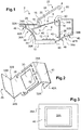
- the figure 1 shows schematically the main components of a head-up display 2 according to the invention, capable of fitting out a motor vehicle.
- the display 2 comprises a housing 4 which contains an image generation device 5 comprising a screen 6 and a light source 8.
- the light source 8 is present here at a bottom 10 of the housing 4.
- the light source comprises a plurality of light-emitting diodes 12 controlled by a control unit not shown.
- the light-emitting diodes 12 are oriented so that their light beams illuminate a front face 14 of the screen 6.
- the light beams mainly backlight a matrix 16 surrounded by a frame 18 of the screen.
- the matrix 16 is a liquid crystal screen comprising a plurality of elements 20 whose transmittance varies in a controlled manner over time (as well as an input polarizer forming the front face 14 of the screen 6 and a outlet forming the rear face 50 of the screen 6).
- the value of the transmittance of each element 20 is controlled by the control unit mentioned above.
- the box 4 can also include an optical system (not shown), such as a deflection mirror, making it possible to modify the properties of the light beam emitted by the screen 6 and transmitted (by the optical system) to a partially transparent blade (for example the vehicle windshield or, alternatively, a dedicated combiner) so as to form a virtual image visible to the driver.
- an optical system such as a deflection mirror, making it possible to modify the properties of the light beam emitted by the screen 6 and transmitted (by the optical system) to a partially transparent blade (for example the vehicle windshield or, alternatively, a dedicated combiner) so as to form a virtual image visible to the driver.
- the box 4 is therefore widened to allow their integration, in particular at the level of an emission opening 22, protected by a window 24, through which the light beam emitted at the outlet of the screen 6 is projected onto the partially transparent blade ( here the windshield).
- the amount of natural light illuminating the screen 6 causes significant heating of the matrix 16, which can damage the latter.
- the invention proposes a new type of head-up display 2, which differs from the state of the art in that it comprises a heat sink 26 of a new kind.
- the Figures 1 to 3 represent a first embodiment of a heat sink 26 according to the invention.
- the heat sink 26 comprises a base 28 superimposed on a part of the screen 6, here on a part of the front face 14 of the screen 6.
- the base 28 covers the entire face of the frame 18 delimiting the contours of the face before 16 of the screen.
- the base 28 includes a skylight 30 centered on the matrix 16.
- the dimensions of the skylight 30 are similar (or, here, slightly greater) than those of the matrix 16. In other words, the dimensions of the skylight 30 are chosen to allow the passage of at least part of the light beam passing through the screen 6 (here the upstream light beam generated by the light source 8).
- the dimensions of the skylight 30 being greater than those of the matrix 16, the skylight 30 allows the passage of the entire light beam.
- the dimensions of the window are smaller than those of the matrix 16, which makes it possible to increase the contact surface between the heat sink 26 and the screen 6; in such a case, the skylight does not allow the entire light beam to pass, but only a part (in substantial practice) thereof.
- the heat sink 26 has two tongues 32A and 32B, extending from the base 28. It should be noted that the invention is not limited to a particular number of tongues.
- the base can include a number of tongues between 1 and 6.
- the tongues 32A and 32B and the base 28 here form a single piece. According to an alternative embodiment not shown, the tongues can be separate parts and held at the base by means of known means.
- a first tongue 32A extends from an edge 34A of the base, to an opening 36A passing through a wall 38A of the housing 4.
- a second tongue 32B extends from an opposite edge 34B of the base, up to an opening 36B passing through another wall 38B of the housing 4.
- Each of the walls 38A, 38B is distant from the image generation device 5, that is to say that the wall concerned extends in all remote point of the image generation device 5.
- Each tab 32A; 32B has intermediate zones (here inflection zones) 40 to allow their distal portion 42A; 42B to be located at an opening 36A; 36B and partially close this opening 36A; 36B. More specifically, the distal part 42A; 42B of each tab 32A; 23B is arranged so as to be flush or substantially flush with the external surface 44 of the housing 4.
- the contours of the openings 36A, 36B and the contours of the distal parts 42A, 42B are thus of complementary shapes.
- inflection zones 40 as intermediate zones (inflection zones having in section non-rectilinear shapes) makes it possible to accommodate within the housing 4 a heat sink 26 having a length (according to this section), and therefore a mass, greater and therefore to improve the heat transfer by conduction and by convection.
- the base 28, the intermediate zone 40 and the distal part 42A is here made in one piece (for example made of metal).
- the dimensions of the distal parts 42A, 42B are here slightly smaller than the dimensions of each opening 36A; 36B, so as to allow the existence of a gap 46 between the edges delimiting each opening 36A; 36B and the edges delimiting the corresponding distal part 42A; 42B of the tabs 32A; 32B. Provision is thus made for the edges delimiting an opening 36A; 36B and the edges delimiting the outline of a tongue 32A; 32B closing said opening 36A; 36B, are separated by a distance allowing the circulation of a natural air flow, but preventing or limiting the introduction of solid or liquid into the housing 4 according to the IP42 standard.
- the value of this distance is equal to or less than 1.2 mm, preferably between 1 mm and 0.6 mm. According to the present example, this distance is equal to 0.8 mm.
- a thermal insulator could be interposed between the edges of the distal portion 42A; 42B of at least one tongue 32A; 32B and the edges of the opening 36A; 36B corresponding so as to seal the housing 4 while avoiding (or at least limiting) the heat transfer between the tongue 32A; 32B concerned and the housing 4.
- each tab 32A; 32B makes it possible to direct or channel a large part of the heat emitted by the screen 6 and transmitted to the base 28, up to an opening 36A, 36B located more or less at a distance from the screen 6.
- the screen 6 can be positioned more freely in the housing 4, independently of the position of the openings 36A and 36B.
- the invention allows greater freedom of shape and dimensions of the housing 4 while allowing better cooling of the screen 6 thanks to the heat sink 26.
- This is particularly advantageous when the shape of the housing is strongly flared downstream of the screen.
- the presence of a gap 46 between the tongue and the edges of the opening 36 advantageously allows the establishment of a natural air flow between the interior and the exterior of the housing 4, to cool all of the elements. contained in said housing. This air flow thus makes it possible to limit the rise in temperature inside the housing 4 in order to preserve the integrity of the electronic components constituting the display 2.
- the heat sink 26 has a thermal conductivity greater than 50 Wm -1 .K -1 , preferably between 200 Wm -1 .K -1 and 260 Wm -1 .K -1 . According to the present example, it is of the order of 230 Wm -1 .K -1 .
- the heat sink 26 has a thickness greater than 1 mm, preferably between 1.5 mm and 2.5 mm. According to present example, it is of the order of 2 mm.
- the density of the heat sink 26 can be between 2,500 kg.m -1 and 3,000 kg.m -1 . According to the present example, it is of the order of 2,700 kg.m -1 .
- the emissivity of the heat sink 26 can be between 0.5 and 0.9, preferably between 0.7 and 0.8. According to the present example, it is of the order of 0.77.
- the heat sink 26 is preferably made from a metallic material, such as for example anodized aluminum, steel, copper or magnesium.
- the base in order to promote efficient transmission of heat between the frame 18 of the screen and the base 28, the base has a flat face opposite the screen 6, the flatness of which is between 0.005 mm.mm -1 and 0.01 mm.mm -1 . According to the present example, it is of the order of 0.007 mm.mm -1 .
- the base 28 can also have a face of complementary shape to the frame 18, when the frame has concave and / or convex zones. In this case, it will be ensured that the variation of the distance between the base and the frame is included in the ranges of values mentioned above.
- a thermal paste can be interposed between the base 28 and the frame 18, in order to ensure better heat transfer between these elements.
- the thermal paste has a thermal conductivity equal to or greater than 3 Wm -1 .K -1 .
- the thickness of the dough can be between 20 ⁇ m and 70 ⁇ m, preferably of the order of 50 ⁇ m.
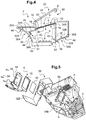
- a translucent plate 48 is interposed between the base 28 of the heat sink 26 and the screen 6.
- This translucent plate 48 is in contact with the heat sink 26, for example at the edges of the skylight 30 formed in the heat sink 26 as explained below, here around the entire periphery of this dormer 30 (over a width of at least 2 mm around the entire periphery of the skylight 30).
- the translucent plate 48 is moreover in contact with the screen 6, precisely the matrix 16 of the screen 6.
- the translucent plate 48 can cover the entire surface of the matrix 16 or only part of it.
- This plate 48 can comprise a polarizing film, composed for example of polymer, capable of absorbing more than 90% of a defined polarity. This polarizing film can then let the light polarized in the direction of the input polarizer of the matrix 16 pass and reflect the light polarized at 90 ° relative to this direction towards the light source 8.
- a polarizing film composed for example of polymer, capable of absorbing more than 90% of a defined polarity. This polarizing film can then let the light polarized in the direction of the input polarizer of the matrix 16 pass and reflect the light polarized at 90 ° relative to this direction towards the light source 8.
- This embodiment advantageously allows, when a reflector 11 is interposed between the light source 8 and the screen 6 (as shown diagrammatically on the figure 4 and visible on the figure 5 ), to recycle the polarized light at 90 ° towards the reflector 11 and thus to reach brightness levels of the matrix 16 which are greater, of the order of 15,000 cd / m 2 up to 50 ° C, for a given supply current level of the light-emitting diodes 12.
- This plate 48 can also include a transparent ceramic plate.
- a ceramic plate may also include a tab closing (at least partially) another opening of the housing 4.
- the transparent ceramic used is for example an aluminum oxide (such as AION, MgAl2O4, Al2O3 or Y3Al5O12).
- Such a ceramic has a thermal conductivity greater than 5 Wm -1 .K -1 , typically between 5 Wm -1 .K -1 and 45 Wm -1 .K -1 . Since ceramic is a good thermal conductor, the use of a ceramic plate in contact with the screen 6 and the heat sink 26 makes it possible to further facilitate the evacuation of the heat (in particular that generated by the screen 6) by the heat sink 26.
- the translucent plate 48 comprises such a ceramic plate and the polarizing film mentioned above.
- the heat sink 26 is mounted (by holding means) on the screen 6 and / or on the housing 4.
- the holding means can be screws 54, glue or the like.
- the base 28 of the heat sink may include passages 52 allowing the passage of fixing screws 54.
- a plate 56 can be superimposed on the base 28 and be fixed to the frame 18 of the screen 6, so that the base 28 is taken in a vice between the plate 56 and the frame 18.
- the plate 56 comprises a skylight 58 so as not to hinder the transmission of the light beam emitted by the screen 6.
- the fixing screws 54 are screwed into an optical conduit 58 present between the light source 8 and the screen 6 This embodiment advantageously makes it possible not to use other means to keep the heat sink 26 fixed relative to the housing 4.
- the image generation device 5 comprises the light source 8, the reflector 11 and the screen 6.
- the heat sink 26 may include fins extending outside the housing 4.
- the fins are for example present at the distal parts 42A, 42B of the heat sink 26.
- the display 2 comprises mechanical means making it possible to establish a forced air flow at the level of the part of the tongue closing an opening of the housing.
- the display 2 comprises a cooling device implementing a thermoelectric effect of the Peltier effect type, at the level of the part of the tongue closing an opening of the housing.
- the housing 4 is made from a metallic material, according to the present example based on magnesium.
- the housing 4 also has slots 60 to allow greater air circulation, in particular at the level of the screen 6 and the light source 8.
- the slots have a width equal to or less than 1 mm in order to comply with the standard IP42.
- the slits are positioned downstream of the screen 6.
- upstream and downstream refer to the direction of propagation of the light beams emitted by the light source 8.
Landscapes
- Engineering & Computer Science (AREA)
- Chemical & Material Sciences (AREA)
- Combustion & Propulsion (AREA)
- Transportation (AREA)
- Mechanical Engineering (AREA)
- Physics & Mathematics (AREA)
- General Physics & Mathematics (AREA)
- Optics & Photonics (AREA)
- Nonlinear Science (AREA)
- Crystallography & Structural Chemistry (AREA)
- Mathematical Physics (AREA)
- Multimedia (AREA)
- Signal Processing (AREA)
- Devices For Indicating Variable Information By Combining Individual Elements (AREA)
- Instrument Panels (AREA)
Abstract
Description
- La présente invention concerne un afficheur tête haute, par exemple pour véhicule automobile.
- Pour le conducteur d'un véhicule automobile, il est confortable de visualiser des informations relatives au fonctionnement du véhicule et/ou à l'état du trafic, sans avoir pour cela à détourner son regard de la chaussée.
- Il est connu pour cela l'utilisation d'un afficheur tête haute comprenant un boîtier renfermant un dispositif de génération d'image comprenant un écran et une source de lumière. L'écran comporte une matrice à cristaux liquides dont la transmittance varie de façon contrôlée dans le temps. La source de lumière est agencée de manière à rétroéclairer l'écran et ainsi former le faisceau lumineux susmentionné, qui se propagea ainsi au-delà dudit écran.
- Ce faisceau lumineux peut alors être projeté, éventuellement par l'intermédiaire d'un système optique, sur une lame partiellement transparente située dans le champ de vision du conducteur.
- Pour ne pas encombrer l'espace situé au-dessus de la planche de bord du véhicule automobile, le pare-brise peut être utilisé en tant que lame partiellement transparente. En variante, on peut utiliser un combineur dédié, situé entre le conducteur et le pare-brise, en tant que lame partiellement transparente.
- Afin d'offrir un confort visuel accru au conducteur, il est préférable que l'information soit perçue dans le champ de vision du conducteur comme étant éloignée. Pour cela, il est nécessaire d'utiliser un système optique avec un facteur d'agrandissement plus important et de ce fait plus encombrant. Le boîtier a donc été élargi pour permettre l'intégration de tel système optique, notamment au niveau de l'ouverture par laquelle l'image optique est projetée sur la lame partiellement transparente.
- L'agrandissement du boîtier au niveau de sa sortie, présente l'inconvénient qu'une plus grande quantité de lumière ambiante pénètre dans le boîtier. Pour certains angles critiques d'ensoleillement, la contrainte d'exposition au rayonnement solaire devient plus problématique. Le système optique focalise la lumière du soleil sur l'écran de l'afficheur, engendrant un échauffement important de ce dernier et, par la même occasion, du conduit optique.
- Les afficheurs tête haute, en particulier ceux utilisant le pare-brise comme lame partiellement transparente, sont donc soumis simultanément à deux contraintes thermiques générées d'une part par l'ensoleillement naturel et d'autre part par la source de lumière présente dans le boîtier. Au-delà d'une température critique à l'intérieur du boîtier, le fonctionnement de l'écran se trouve altéré et l'image projetée sur la lame partiellement transparente devient alors moins visible ou plus visible.
- Il est donc apparu le besoin de trouver un nouveau type de dissipateur thermique, permettant un refroidissement plus efficace de l'écran d'un afficheur tête haute, lorsqu'il est soumis aux contraintes thermiques mentionnées ci-dessus.
- Dans ce contexte, la présente invention propose un afficheur tête haute pour véhicule automobile, comprenant un dissipateur thermique et un boîtier renfermant un dispositif de génération d'image comprenant un écran et une source de lumière, l'écran comportant un cadre entourant une matrice constituée d'éléments dont la transmittance varie de façon contrôlée dans le temps, la source de lumière étant agencée de manière à éclairer une face avant de l'écran pour former un faisceau lumineux.
- L'invention est remarquable en ce que le boîtier comprend une paroi distante du dispositif de génération d'image et comportant au moins une ouverture, le dissipateur thermique comprenant une base superposée au cadre de l'écran (en étant par exemple en contact avec le cadre de l'écran), la base servant de support à au moins une languette obturant partiellement ladite ouverture.
- Le dissipateur thermique permet de dissiper la chaleur générée par l'écran. Selon l'invention, un dissipateur thermique comporte une base positionnée à proximité de l'écran afin d'absorber la chaleur qu'il génère. La chaleur emmagasinée par la base est dirigée jusqu'à l'extérieur du boîtier, par l'intermédiaire d'une languette s'étendant de la base jusqu'à une ouverture du boîtier optique. En d'autres termes, la languette permet de diriger une grande partie de la chaleur émise par l'écran jusqu'à une ouverture située à distance de l'écran.
- Le dissipateur thermique selon l'invention permet ainsi un refroidissement plus efficace de l'écran en évacuant principalement la chaleur à l'extérieur du boîtier optique.
- Selon un autre avantage, l'invention permet également une plus grande liberté d'agencement de l'écran par rapport à la position de l'ouverture sur le boîtier optique. Cela est particulièrement avantageux lorsque les contraintes d'intégration ne permettent pas la présence d'une ouverture à proximité immédiate de l'écran.
- Selon une autre caractéristique de l'invention, la languette obture partiellement une ouverture du boîtier optique de manière à permettre le passage d'un flux d'air naturel entre l'intérieur et l'extérieur du boîtier. Ce flux d'air permet avantageusement de limiter l'élévation de température à l'intérieur de l'ensemble du boîtier optique.
- Ainsi, la languette du dissipateur thermique et son positionnement dans une ouverture du boîtier optique, permettent un refroidissement plus efficace de l'intérieur du boîtier optique et en particulier au niveau de son écran.
- D'autres caractéristiques non limitatives et avantageuses du dispositif conforme à l'invention sont les suivantes :
- Les bords en vis-à-vis, délimitant l'ouverture et la languette, sont écartés d'une distance (non-nulle) égale ou inférieure à 1,2 mm, de préférence comprise entre 1 mm et 0,6 mm ;
- le dissipateur thermique a une conductivité thermique supérieure à la conductivité thermique du cadre de l'écran ;
- le dissipateur thermique a une conductivité thermique supérieure à 50 W.m-1.K-1, de préférence comprise entre 200 W.m-1.K-1 et 260 W.m-1.K-1, de préférence de l'ordre de 230 W.m-1.K-1;
- le dissipateur thermique a une épaisseur supérieure à 1 mm, de préférence comprise entre 1,5 mm et 2,5 mm ;
- le boîtier optique est réalisé à partir de magnésium et/ou le dissipateur thermique est réalisé à partir d'aluminium ;
- la base du dissipateur thermique est placée en vis-à-vis d'une face arrière de l'écran, opposée à la face avant dudit écran ;
- la variation de l'écart, entre la base et le cadre de l'écran, est inférieure à 0,01 mm, de préférence comprise entre 0,009 mm et 0,005 mm, de préférence de l'ordre de 0,007 mm ;
- la base du dissipateur thermique comporte une lucarne en vis-à-vis de la matrice de l'écran ;
- le dissipateur thermique sert de support à une autre languette obturant partiellement un autre passage du boîtier optique ;
- une partie de la languette (par exemple une zone intermédiaire s'étendant entre la base et une partie distale obturant l'ouverture) s'étend à travers un espace libre défini entre le dispositif de génération d'image et le boîtier ;
- le dispositif de génération d'image comprend une plaque en céramique transparente interposée entre l'écran et la base du dissipateur thermique ;
- la plaque en céramique transparente est au contact d'une part de la matrice et d'autre part de la base, ce qui facilite encore l'évacuation de la chaleur générée par l'écran par le dissipateur thermique.
- La présente demande concerne également un véhicule automobile comprenant un afficheur tête haute tel que décrit ci-dessus.
- Bien entendu, les différentes caractéristiques, variantes et formes de réalisation mentionnées ci-dessus peuvent être associées les unes avec les autres selon diverses combinaisons, dans la mesure où elles ne sont pas incompatibles ou exclusives les unes des autres.
- La description qui va suivre en regard des dessins annexés, donnés à titre d'exemples non limitatifs, fera bien comprendre en quoi consiste l'invention et comment elle peut être réalisée. Sur les dessins annexés :
- la
figure 1 illustre une représentation schématique d'une coupe longitudinale d'un afficheur tête haute selon l'invention ; - la
figure 2 illustre une vue en perspective d'un dissipateur thermique contenu dans l'afficheur représenté par lafigure 1 ; - la
figure 3 illustre une vue de face d'une paroi extérieure du boîtier optique représenté par lafigure 1 , comprenant une ouverture partiellement obturée par une extrémité distale du dissipateur thermique représenté par lafigure 2 ; - la
figure 4 illustre une représentation schématique d'une variante de réalisation d'un afficheur représenté par lafigure 1 ; et - la
figure 5 illustre une vue en éclatée d'une variante de réalisation d'un afficheur représenté par lafigure 1 . - Pour rappel, l'invention concerne un nouveau type de dissipateur thermique, permettant un refroidissement plus efficace d'un écran d'afficheur tête haute lorsqu'il est soumis à de fortes contraintes thermiques.
- La
figure 1 représente de façon schématique les composants principaux d'un afficheur 2 tête haute selon l'invention, apte à équiper un véhicule automobile. - L'afficheur 2 comporte un boîtier 4 qui renferme un dispositif de génération d'image 5 comprenant un écran 6 et une source de lumière 8. La source de lumière 8 est présente ici au niveau d'un fond 10 du boîtier 4. Selon le présent exemple, la source de lumière comprend une pluralité de diodes électroluminescentes 12 pilotées par une unité de commande non représentée. Les diodes électroluminescentes 12 sont orientées de sorte que leurs faisceaux lumineux éclairent une face avant 14 de l'écran 6. De préférence, les faisceaux lumineux rétroéclairent majoritairement une matrice 16 entourée par un cadre 18 de l'écran. La matrice 16 est un écran à cristaux liquides comprenant une pluralité d'éléments 20 dont la transmittance varie de façon contrôlée au cours du temps (ainsi qu'un polariseur d'entrée formant la face avant 14 de l'écran 6 et un polariseur de sortie formant la face arrière 50 de l'écran 6). La valeur de la transmittance de chaque élément 20 est pilotée par l'unité de commande mentionnée ci-dessus.
- Le boîtier 4 peut également comporter un système optique (non représenté), tel qu'un miroir de renvoi, permettant de modifier les propriétés du faisceau lumineux émis par l'écran 6 et transmis (par le système optique) vers une lame partiellement transparente (par exemple le pare-brise du véhicule ou, en variante, un combineur dédié) de manière à former une image virtuelle visible par le conducteur.
- Comme mentionné ci-dessus, afin d'offrir un confort visuel accru au conducteur d'un véhicule automobile, on souhaite que l'information soit perçue par le conducteur comme étant distante dans son champ de vision. Pour cela, il est nécessaire d'utiliser un système optique avec un facteur d'agrandissement plus important et donc plus encombrant. Le boîtier 4 est donc élargi pour permettre leur intégration, notamment au niveau d'une ouverture d'émission 22, protégée par une vitre 24, par laquelle le faisceau lumineux émis en sortie de l'écran 6 est projeté sur la lame partiellement transparente (ici le pare-brise). Pour certaines heures d'ensoleillement, la quantité de lumière naturelle éclairant l'écran 6 entraine un échauffement important de la matrice 16, susceptible d'endommager cette dernière. Pour éviter cela, l'invention propose un nouveau type d'afficheur tête haute 2, se distinguant de l'état de la technique en ce qu'il comprend un dissipateur thermique 26 d'un nouveau genre.
- Les
figures 1 à 3 représentent un premier mode de réalisation d'un dissipateur thermique 26 selon l'invention. Le dissipateur thermique 26 comprend une base 28 superposée à une partie de l'écran 6, ici à une partie de la face avant 14 de l'écran 6. De préférence, la base 28 recouvre la totalité de la face du cadre 18 délimitant les contours de la face avant 16 de l'écran. Comme illustré par lafigure 2 , la base 28 comporte une lucarne 30 centrée sur la matrice 16. Les dimensions de la lucarne 30 sont similaires (ou, ici, légèrement supérieures) à celles de la matrice 16. En d'autres termes, les dimensions de la lucarne 30 sont choisies pour permettre le passage d'au moins une partie du faisceau lumineux traversant l'écran 6 (ici du faisceau lumineux amont généré par la source de lumière 8). - Dans l'exemple décrit, les dimensions de la lucarne 30 étant supérieures à celles de la matrice 16, la lucarne 30 permet le passage de l'intégralité du faisceau lumineux. On peut toutefois prévoir en variante que les dimensions de la lucarne soient inférieures à celles de la matrice 16, ce qui permet d'augmenter la surface de contact entre le dissipateur thermique 26 et l'écran 6 ; dans un tel cas, la lucarne ne laisse passer l'intégralité du faisceau lumineux, mais seulement une partie (en pratique substantielle) de celui-ci.
- Le dissipateur thermique 26 comporte deux languettes 32A et 32B, s'étendant à partir de la base 28. Il est à noter que l'invention n'est pas limitée à un nombre particulier de languettes. Par exemple, la base peut comprendre un nombre de languettes compris entre 1 et 6. Les languettes 32A et 32B et la base 28 forment ici une seule et même pièce. Selon une variante de réalisation non représentée, les languettes peuvent être des pièces distinctes et maintenues à la base par l'intermédiaire de moyens connus.
- Comme illustré par les
figures 2 et 3 , une première languette 32A s'étend à partir d'un bord 34A de la base, jusqu'à une ouverture 36A traversant une paroi 38A du boîtier 4. Une deuxième languette 32B s'étend à partir d'un bord 34B opposé de la base, jusqu'à une ouverture 36B traversant une autre paroi 38B du boîtier 4. Chacune des parois 38A, 38B est distante du dispositif de génération d'image 5, c'est-à-dire que la paroi concernée s'étend en tout point à distance du dispositif de génération d'image 5. - Chaque languette 32A ; 32B comporte des zones intermédiaires (ici des zones d'inflexion) 40 pour permettre à leur partie distale 42A ; 42B d'être située au niveau d'une ouverture 36A ; 36B et d'obturer partiellement cette ouverture 36A ; 36B. Plus précisément, la partie distale 42A ; 42B de chaque languette 32A ; 23B est agencée de sorte à affleurer ou sensiblement affleurer la surface externe 44 du boîtier 4. Les contours des ouvertures 36A, 36B et les contours des parties distales 42A, 42B sont ainsi de formes complémentaires.
- Chacune des parois 38A, 38B étant distante du dispositif de génération d'image 5, les zones intermédiaires 40 des languettes 32A, 23B s'étendent chacune dans l'espace libre situé entre le dispositif de génération d'image 5 et le boîtier 4 (c'est-à-dire à travers l'espace libre situé dans le boîtier 4 et entourant le dispositif de génération d'image 5), ce qui facilite la dissipation de chaleur.
- L'utilisation de zones d'inflexion 40 en tant que zones intermédiaires (zones d'inflexion ayant en section des formes non rectilignes) permet de loger au sein du boîtier 4 un dissipateur thermique 26 ayant une longueur (selon cette section), et donc une masse, plus importante et donc d'améliorer le transfert thermique par conduction et par convection.
- Comme déjà indiqué, la base 28, la zone intermédiaire 40 et la partie distale 42A est ici réalisé d'une pièce (par exemple en métal).
- Il est à noter que les dimensions des parties distales 42A, 42B sont ici légèrement inférieures aux dimensions de chaque ouverture 36A ; 36B, de sorte à permettre l'existence d'un interstice 46 entre les bords délimitant chaque ouverture 36A ; 36B et les bords délimitant la partie distale correspondante 42A ; 42B des languettes 32A ; 32B. On prévoit ainsi que les bords délimitant une ouverture 36A ; 36B et les bords délimitant le contour d'une languette 32A ; 32B obturant ladite ouverture 36A ; 36B, soient écartées d'une distance permettant la circulation d'un flux d'air naturel, mais empêchant ou limitant l'introduction de solide ou de liquide dans le boîtier 4 selon la norme IP42. De préférence, la valeur de cette distance est égale ou inférieure à 1,2 mm, de préférence comprise entre 1 mm et 0,6 mm. Selon le présent exemple, cette distance est égale à 0,8 mm.
- En variante, un isolant thermique pourrait être interposé entre les bords de la partie distale 42A ; 42B d'au moins une languette 32A ; 32B et les bords de l'ouverture 36A ; 36B correspondante de manière à assurer l'étanchéité du boîtier 4 tout en évitant (ou du moins en limitant) le transfert thermique entre la languette 32A ; 32B concernée et le boîtier 4.
- De façon avantageuse, chaque languette 32A ; 32B permet de diriger ou de canaliser une grande partie de la chaleur émise par l'écran 6 et transmise à la base 28, jusqu'à une ouverture 36A, 36B située plus ou moins à distance de l'écran 6. De ce fait, l'écran 6 peut être positionné de façon plus libre dans le boîtier 4, indépendamment de la position des ouvertures 36A et 36B. Ainsi, l'invention permet une plus grande liberté de formes et de dimensions du boîtier 4 tout en permettant un meilleur refroidissement de l'écran 6 grâce au dissipateur thermique 26. Cela est particulièrement avantageux lorsque la forme du boîtier est fortement évasée en aval de l'écran. La présence d'un interstice 46 entre la languette et les bords de l'ouverture 36 permet avantageusement l'établissement d'un flux d'air naturel entre l'intérieur et l'extérieur du boîtier 4, pour refroidir l'ensemble des éléments contenus dans ledit boîtier. Ce flux d'air permet ainsi de limiter l'élévation de température à l'intérieur du boîtier 4 afin de préserver l'intégrité des composants électroniques constituant l'afficheur 2.
- Des possibilités de réalisation de certains aspects de l'afficheur tête haute 2 sont présentées ci-après ; ces différentes possibilités peuvent être combinées entre elles pour obtenir d'autres modes de réalisation non explicitement décrits.
- Selon une possibilité de réalisation, le dissipateur thermique 26 a une conductivité thermique supérieure à 50 W.m-1.K-1, de préférence comprise entre 200 W.m-1.K-1 et 260 W.m-1.K-1. Selon le présent exemple, elle est de l'ordre de 230 W.m-1.K-1.
- Par ailleurs, afin de permettre au dissipateur thermique 26 d'avoir une rigidité mécanique suffisante pour éviter sa mise en vibration et l'émission de bruit lors du déplacement du véhicule, le dissipateur thermique a une épaisseur supérieure à 1 mm, de préférence comprise entre 1,5 mm et 2,5 mm. Selon le présent exemple, elle est de l'ordre de 2 mm.
- La masse volumique du dissipateur thermique 26 peut être comprise entre 2 500 kg.m-1 et 3 000 kg.m-1. Selon le présent exemple, elle est de l'ordre de 2 700 kg.m-1.
- L'émissivité du dissipateur thermique 26 peut être comprise entre 0,5 et 0,9, de préférence entre 0,7 et 0,8. Selon le présent exemple, elle est de l'ordre de 0,77.
- Le dissipateur thermique 26 est de préférence réalisé à partir d'un matériau métallique, comme par exemple de l'aluminium anodisé, de l'acier, du cuivre ou du magnésium.
- Selon une possibilité de réalisation, afin de favoriser une transmission efficace de la chaleur entre le cadre 18 de l'écran et la base 28, la base présente une face plate en vis-à-vis de l'écran 6, dont la platitude est comprise entre 0,005 mm.mm-1 et 0,01 mm.mm-1. Selon le présent exemple, elle est de l'ordre de 0,007 mm.mm-1. Bien entendu, la base 28 peut également présenter une face de forme complémentaire au cadre 18, lorsque le cadre comporte des zones concaves et/ou convexes. Dans ce cas, on veillera à ce que la variation de la distance ente la base et le cadre soit comprise dans les plages de valeurs mentionnées ci-dessus.
- Selon une variante de réalisation, une pâte thermique peut être interposée entre la base 28 et le cadre 18, afin d'assurer un meilleur transfert de chaleur entre ces éléments. De préférence, la pâte thermique a une conductivité thermique égale ou supérieure à 3 W.m-1.K-1. L'épaisseur de la pâte peut être comprise entre 20 µm et 70 µm, de préférence de l'ordre de 50 µm.
- Selon une autre possibilité de réalisation illustrée par la
figure 4 , une plaque translucide 48 est interposée entre la base 28 du dissipateur thermique 26 et l'écran 6. Cette plaque translucide 48 est au contact du dissipateur thermique 26, par exemple au niveau des bords de la lucarne 30 formée dans le dissipateur thermique 26 comme expliqué plus bas, ici sur tout le pourtour de cette lucarne 30 (sur une largeur d'au moins 2 mm sur tout le pourtour de la lucarne 30). - La plaque translucide 48 est par ailleurs au contact de l'écran 6, précisément de la matrice 16 de l'écran 6. La plaque translucide 48 peut couvrir toute la surface de la matrice 16 ou seulement une partie de celle-ci.
- Cette plaque 48 peut comprendre un film polarisant, composé par exemple de polymère, apte à absorber plus de 90% d'une polarité définie. Ce film polarisant peut alors laisser passer la lumière polarisée selon la direction du polariseur d'entrée de la matrice 16 et réfléchir vers la source de lumière 8 la lumière polarisée à 90° par rapport à cette direction. Ce mode de réalisation permet avantageusement, lorsqu'un réflecteur 11 est interposé entre la source de lumière 8 et l'écran 6 (comme représenté schématiquement sur la
figure 4 et visible sur lafigure 5 ), de recycler la lumière polarisée à 90° vers le réflecteur 11 et d'atteindre ainsi des niveaux de luminosité de la matrice 16 qui sont plus importants, de l'ordre de 15 000 cd/m2 jusqu'à 50°C, pour un niveau de courant d'alimentation donné des diodes électroluminescentes 12. - Cette plaque 48 peut également comprendre une plaque en céramique transparente. Une telle plaque en céramique peut également comporter une languette obturant (au moins partiellement) une autre ouverture du boîtier 4. La céramique transparente utilisée est par exemple un oxyde d'aluminium (tel que AION, MgAl2O4, Al2O3 ou Y3Al5O12). Une telle céramique a une conductivité thermique supérieure à 5 W.m-1.K-1, typiquement comprise entre 5 W.m-1.K-1 et 45 W.m-1.K-1. La céramique étant un bon conducteur thermique, l'utilisation d'une plaque en céramique au contact de l'écran 6 et du dissipateur thermique 26 permet de faciliter encore l'évacuation de la chaleur (en particulier celle générée par l'écran 6) par le dissipateur thermique 26.
- Selon une possibilité de mise en oeuvre, la plaque translucide 48 comporte une telle plaque en céramique et le film polarisant mentionné ci-dessus.
- Selon une possibilité de réalisation, le dissipateur thermique 26 est monté (par des moyens de maintien) sur l'écran 6 et/ou sur le boîtier 4. Les moyens de maintien peuvent être des vis 54, de la colle ou autres. Comme illustré par la
figure 5 , la base 28 du dissipateur thermique peut comporter des passages 52 permettant le passage de vis 54 de fixation. Selon un mode de réalisation préféré illustré par lafigure 5 , une plaque 56 peut être superposée à la base 28 et être fixée sur le cadre 18 de l'écran 6, de sorte que la base 28 soit prise en étau entre la plaque 56 et le cadre 18. Bien entendu, la plaque 56 comporte une lucarne 58 de sorte à ne pas gêner la transmission du faisceau lumineux émis par l'écran 6. Il est à noter que les vis de fixation 54 sont vissées dans un conduit optique 58 présent entre la source de lumière 8 et l'écran 6. Ce mode de réalisation permet avantageusement de ne pas utiliser d'autres moyens pour maintenir fixe le dissipateur thermique 26 par rapport au boîtier 4. - Comme déjà indiqué, dans le mode de réalisation de la
figure 5 , le dispositif de génération d'image 5 comprend la source de lumière 8, le réflecteur 11 et l'écran 6. - Selon une possibilité de réalisation, le dissipateur thermique 26 peut comporter des ailettes s'étendant à l'extérieur du boîtier 4. Les ailettes sont par exemple présentes au niveau des parties distales 42A, 42B du dissipateur thermique 26.
- Selon une possibilité de réalisation, l'afficheur 2 comporte des moyens mécaniques permettant d'établir un flux d'air forcé au niveau de la partie de la languette obturant une ouverture du boîtier. Selon un autre mode de réalisation, l'afficheur 2 comporte un dispositif de refroidissement mettant en oeuvre un effet thermoélectrique de type effet Peltier, au niveau de la partie de la languette obturant une ouverture du boîtier.
- Selon une autre possibilité de réalisation, le boîtier 4 est réalisé à partir d'un matériau métallique, selon le présent exemple à base de magnésium. Le boîtier 4 comporte également des fentes 60 pour permettre une plus grande circulation d'air, notamment au niveau de l'écran 6 et de la source de lumière 8. Les fentes ont une largeur égale ou inférieure à 1 mm afin de respecter la norme IP42. De préférence, les fentes sont positionnées en aval de l'écran 6. Les termes « amont » et « aval » se réfèrent au sens de propagation des faisceaux lumineux émis par la source de lumière 8.
Claims (14)
- Afficheur (2) tête haute comprenant un dissipateur thermique (26) et un boîtier (4) renfermant un dispositif de génération d'image (5) comprenant un écran (6) et une source de lumière (8), l'écran (6) comportant un cadre (18) entourant une matrice (16) constituée d'éléments (20) dont la transmittance varie de façon contrôlée dans le temps, la source de lumière (8) étant agencée de manière à éclairer une face avant (14) de l'écran (6) pour former un faisceau lumineux, caractérisé en ce que le boîtier (4) comprend une paroi (38A ; 38B) distante du dispositif de génération d'image (5) et comportant au moins une ouverture (36A ; 36B), le dissipateur thermique (26) comprenant une base (28) superposée au cadre de l'écran (6), la base (28) servant de support à au moins une languette (32A ; 32B) obturant partiellement ladite ouverture (36A ; 36B).
- Afficheur (2) selon la revendication précédente, caractérisé en ce que les bords en vis-à-vis, délimitant l'ouverture (36A ; 36B) et la languette (32A ; 32B), sont écartés d'une distance égale ou inférieure à 1,2 mm.
- Afficheur (2) selon l'une des revendications précédentes, caractérisé en ce que le dissipateur thermique (26) a une conductivité thermique supérieure à la conductivité thermique du cadre de l'écran (6).
- Afficheur (2) selon l'une des revendications précédentes, caractérisé en ce que le dissipateur thermique (26) a une conductivité thermique supérieure à 50 W.m-1.K-1.
- Afficheur (2) selon l'une des revendications précédentes, caractérisé en ce que le dissipateur thermique (26) a une épaisseur supérieure à 1 mm.
- Afficheur (2) selon l'une des revendications précédentes, caractérisé en ce que le dissipateur thermique (26) est réalisé à partir d'aluminium.
- Afficheur (2) selon l'une des revendications précédentes, caractérisé en ce que le boîtier optique (4) est réalisé à partir de magnésium.
- Afficheur (2) selon l'une des revendications précédentes, caractérisé en ce que la base (28) du dissipateur thermique (26) est placée en vis-à-vis de la face avant (14) de l'écran (6).
- Afficheur (2) selon l'une des revendications précédentes, caractérisé en ce que la variation de l'écart, entre la base (28) et le cadre de l'écran (6), est inférieure à 0,01 mm.
- Afficheur (2) selon la revendication 8 ou 9, caractérisé en ce que la base (28) du dissipateur thermique (26) comporte une lucarne (30) en vis-à-vis de la matrice de l'écran (6).
- Afficheur (2) selon l'une des revendications précédentes, caractérisé en ce que le dissipateur thermique (26) sert de support à une autre languette (32B) obturant partiellement une autre ouverture (36B) du boîtier optique (4).
- Afficheur (2) selon l'une des revendications précédentes, caractérisé en ce que une partie (40) de la languette (32A ; 32B) s'étend à travers un espace libre défini entre le dispositif de génération d'image (5) et le boîtier (4).
- Afficheur (2) selon l'une des revendications précédentes, caractérisé en ce que le dispositif de génération d'image (5) comprend une plaque (48) en céramique transparente interposée entre l'écran (6) et la base (28) du dissipateur thermique (26).
- Afficheur (2) selon la revendication précédente, caractérisé en ce que la plaque (48) en céramique transparente est au contact d'une part de la matrice (16) et d'autre part de la base (28).
Priority Applications (1)
| Application Number | Priority Date | Filing Date | Title |
|---|---|---|---|
| EP18209752.7A EP3663827A1 (fr) | 2018-12-03 | 2018-12-03 | Afficheur tête haute |
Applications Claiming Priority (1)
| Application Number | Priority Date | Filing Date | Title |
|---|---|---|---|
| EP18209752.7A EP3663827A1 (fr) | 2018-12-03 | 2018-12-03 | Afficheur tête haute |
Publications (1)
| Publication Number | Publication Date |
|---|---|
| EP3663827A1 true EP3663827A1 (fr) | 2020-06-10 |
Family
ID=64572170
Family Applications (1)
| Application Number | Title | Priority Date | Filing Date |
|---|---|---|---|
| EP18209752.7A Pending EP3663827A1 (fr) | 2018-12-03 | 2018-12-03 | Afficheur tête haute |
Country Status (1)
| Country | Link |
|---|---|
| EP (1) | EP3663827A1 (fr) |
Cited By (2)
| Publication number | Priority date | Publication date | Assignee | Title |
|---|---|---|---|---|
| FR3115611A1 (fr) * | 2020-10-26 | 2022-04-29 | Valeo Comfort And Driving Assistance | Dispositif d’assemblage adapté pour assembler un écran avec un élément partiellement transparent et afficheur tête haute comprenant un tel dispositif |
| FR3140680A1 (fr) * | 2022-10-05 | 2024-04-12 | Valeo Comfort And Driving Assistance | Afficheur tête-haute |
Citations (4)
| Publication number | Priority date | Publication date | Assignee | Title |
|---|---|---|---|---|
| JP2007086387A (ja) * | 2005-09-22 | 2007-04-05 | Nippon Seiki Co Ltd | 車両用表示装置 |
| JP2009151249A (ja) * | 2007-12-24 | 2009-07-09 | Nippon Seiki Co Ltd | 液晶表示装置 |
| JP2011158862A (ja) * | 2010-02-04 | 2011-08-18 | Mitsubishi Electric Corp | 投影装置 |
| US20160320691A1 (en) * | 2015-04-30 | 2016-11-03 | Dimitar Andreev | Device for the emission of light, in particular for the generation of an image |
-
2018
- 2018-12-03 EP EP18209752.7A patent/EP3663827A1/fr active Pending
Patent Citations (4)
| Publication number | Priority date | Publication date | Assignee | Title |
|---|---|---|---|---|
| JP2007086387A (ja) * | 2005-09-22 | 2007-04-05 | Nippon Seiki Co Ltd | 車両用表示装置 |
| JP2009151249A (ja) * | 2007-12-24 | 2009-07-09 | Nippon Seiki Co Ltd | 液晶表示装置 |
| JP2011158862A (ja) * | 2010-02-04 | 2011-08-18 | Mitsubishi Electric Corp | 投影装置 |
| US20160320691A1 (en) * | 2015-04-30 | 2016-11-03 | Dimitar Andreev | Device for the emission of light, in particular for the generation of an image |
Cited By (3)
| Publication number | Priority date | Publication date | Assignee | Title |
|---|---|---|---|---|
| FR3115611A1 (fr) * | 2020-10-26 | 2022-04-29 | Valeo Comfort And Driving Assistance | Dispositif d’assemblage adapté pour assembler un écran avec un élément partiellement transparent et afficheur tête haute comprenant un tel dispositif |
| WO2022090233A1 (fr) * | 2020-10-26 | 2022-05-05 | Valeo Comfort And Driving Assistance | Dispositif d'assemblage adapté pour assembler un écran avec un élément partiellement transparent et afficheur tête haute comprenant un tel dispositif |
| FR3140680A1 (fr) * | 2022-10-05 | 2024-04-12 | Valeo Comfort And Driving Assistance | Afficheur tête-haute |
Similar Documents
| Publication | Publication Date | Title |
|---|---|---|
| EP3224669B1 (fr) | Dispositif de rétroéclairage notamment pour afficheur tête haute et afficheur tête haute pour véhicule automobile | |
| EP3479156B1 (fr) | Dispositif de génération d'images comprenant une zone de contact thermique, et afficheur tête haute associé | |
| EP3663827A1 (fr) | Afficheur tête haute | |
| EP3479167B1 (fr) | Ecran à cristaux liquides, dispositif de génération d'image comprenant un tel écran et afficheur tête haute comprenant un tel dispositif | |
| FR3020148B1 (fr) | Systeme de generation d'images pour afficheur et afficheur associe | |
| FR3058236B1 (fr) | Ecran a cristaux liquides, dispositif de generation d'image comprenant un tel ecran et afficheur tete haute comprenant un tel dispositif | |
| EP3491444B1 (fr) | Dispositif de génération d'images et afficheur tête haute associé | |
| EP3440504B1 (fr) | Dispositif de génération d'image, afficheur tête haute comprenant un tel dispositif | |
| EP3631563B1 (fr) | Afficheur tête haute pour véhicule automobile | |
| EP3132304A1 (fr) | Dispositif de rétroéclairage notamment pour afficheur tête haute et afficheur tête haute pour véhicule automobile | |
| EP4639260A1 (fr) | Dispositif de génération d'images et afficheur tête haute comportant un tel dispositif | |
| EP3663834A1 (fr) | Afficheur tête haute pour véhicule automobile comprenant un radiateur pour refroidir un écran rétroéclairé | |
| FR3054329B1 (fr) | Dispositif de generation d'image et afficheur tete haute comprenant un tel dispositif de generation d'image | |
| EP4232866A1 (fr) | Dispositif d'assemblage adapté pour assembler un écran avec un élément partiellement transparent et afficheur tête haute comprenant un tel dispositif | |
| FR3140680A1 (fr) | Afficheur tête-haute | |
| FR3104319A1 (fr) | Dispositif de génération d’image avec un dispositif de refroidissement et afficheur tête haute associé | |
| EP4378162A1 (fr) | Dispositif de generation d'images et afficheur tete haute comportant un tel dispositif | |
| EP3667383A1 (fr) | Afficheur tête haute pour véhicule automobile | |
| FR3066836A1 (fr) | Dispositif de generation d'images pour vehicule automobile et afficheur tete haute associe | |
| EP4423562A1 (fr) | Dispositif de génération d'images | |
| FR3006643A1 (fr) | Dispositif lumineux, notamment de vehicule automobile | |
| FR3102572A1 (fr) | Dispositif de génération d’image et dispositif d’affichage tête haute associé |
Legal Events
| Date | Code | Title | Description |
|---|---|---|---|
| PUAI | Public reference made under article 153(3) epc to a published international application that has entered the european phase |
Free format text: ORIGINAL CODE: 0009012 |
|
| STAA | Information on the status of an ep patent application or granted ep patent |
Free format text: STATUS: THE APPLICATION HAS BEEN PUBLISHED |
|
| AK | Designated contracting states |
Kind code of ref document: A1 Designated state(s): AL AT BE BG CH CY CZ DE DK EE ES FI FR GB GR HR HU IE IS IT LI LT LU LV MC MK MT NL NO PL PT RO RS SE SI SK SM TR |
|
| AX | Request for extension of the european patent |
Extension state: BA ME |
|
| RBV | Designated contracting states (corrected) |
Designated state(s): AL AT BE BG CH CY CZ DE DK EE ES FI FR GB GR HR HU IE IS IT LI LT LU LV MC MK MT NL NO PL PT RO RS SE SI SK SM TR |
|
| RAP3 | Party data changed (applicant data changed or rights of an application transferred) |
Owner name: VALEO COMFORT AND DRIVING ASSISTANCE |
|
| P01 | Opt-out of the competence of the unified patent court (upc) registered |
Effective date: 20230528 |
|
| RAP3 | Party data changed (applicant data changed or rights of an application transferred) |
Owner name: VALEO COMFORT AND DRIVING ASSISTANCE |