EP3663870B1 - Moteur electrique à courant continu a inducteurs de stator asymetriques - Google Patents
Moteur electrique à courant continu a inducteurs de stator asymetriques Download PDFInfo
- Publication number
- EP3663870B1 EP3663870B1 EP18210866.2A EP18210866A EP3663870B1 EP 3663870 B1 EP3663870 B1 EP 3663870B1 EP 18210866 A EP18210866 A EP 18210866A EP 3663870 B1 EP3663870 B1 EP 3663870B1
- Authority
- EP
- European Patent Office
- Prior art keywords
- inductor
- stator
- rotor
- inductors
- motor
- Prior art date
- Legal status (The legal status is an assumption and is not a legal conclusion. Google has not performed a legal analysis and makes no representation as to the accuracy of the status listed.)
- Active
Links
Images

Classifications
-
- H—ELECTRICITY
- H02—GENERATION; CONVERSION OR DISTRIBUTION OF ELECTRIC POWER
- H02P—CONTROL OR REGULATION OF ELECTRIC MOTORS, ELECTRIC GENERATORS OR DYNAMO-ELECTRIC CONVERTERS; CONTROLLING TRANSFORMERS, REACTORS OR CHOKE COILS
- H02P7/00—Arrangements for regulating or controlling the speed or torque of electric DC motors
- H02P7/06—Arrangements for regulating or controlling the speed or torque of electric DC motors for regulating or controlling an individual DC dynamo-electric motor by varying field or armature current
- H02P7/18—Arrangements for regulating or controlling the speed or torque of electric DC motors for regulating or controlling an individual DC dynamo-electric motor by varying field or armature current by master control with auxiliary power
- H02P7/24—Arrangements for regulating or controlling the speed or torque of electric DC motors for regulating or controlling an individual DC dynamo-electric motor by varying field or armature current by master control with auxiliary power using discharge tubes or semiconductor devices
- H02P7/28—Arrangements for regulating or controlling the speed or torque of electric DC motors for regulating or controlling an individual DC dynamo-electric motor by varying field or armature current by master control with auxiliary power using discharge tubes or semiconductor devices using semiconductor devices
- H02P7/285—Arrangements for regulating or controlling the speed or torque of electric DC motors for regulating or controlling an individual DC dynamo-electric motor by varying field or armature current by master control with auxiliary power using discharge tubes or semiconductor devices using semiconductor devices controlling armature supply only
- H02P7/29—Arrangements for regulating or controlling the speed or torque of electric DC motors for regulating or controlling an individual DC dynamo-electric motor by varying field or armature current by master control with auxiliary power using discharge tubes or semiconductor devices using semiconductor devices controlling armature supply only using pulse modulation
- H02P7/291—Arrangements for regulating or controlling the speed or torque of electric DC motors for regulating or controlling an individual DC dynamo-electric motor by varying field or armature current by master control with auxiliary power using discharge tubes or semiconductor devices using semiconductor devices controlling armature supply only using pulse modulation with on-off control between two set points, e.g. controlling by hysteresis
-
- H—ELECTRICITY
- H02—GENERATION; CONVERSION OR DISTRIBUTION OF ELECTRIC POWER
- H02P—CONTROL OR REGULATION OF ELECTRIC MOTORS, ELECTRIC GENERATORS OR DYNAMO-ELECTRIC CONVERTERS; CONTROLLING TRANSFORMERS, REACTORS OR CHOKE COILS
- H02P7/00—Arrangements for regulating or controlling the speed or torque of electric DC motors
- H02P7/06—Arrangements for regulating or controlling the speed or torque of electric DC motors for regulating or controlling an individual DC dynamo-electric motor by varying field or armature current
-
- G—PHYSICS
- G04—HOROLOGY
- G04C—ELECTROMECHANICAL CLOCKS OR WATCHES
- G04C3/00—Electromechanical clocks or watches independent of other time-pieces and in which the movement is maintained by electric means
- G04C3/16—Electromechanical clocks or watches independent of other time-pieces and in which the movement is maintained by electric means incorporating an electro-dynamic continuously rotating motor
-
- H—ELECTRICITY
- H02—GENERATION; CONVERSION OR DISTRIBUTION OF ELECTRIC POWER
- H02K—DYNAMO-ELECTRIC MACHINES
- H02K21/00—Synchronous motors having permanent magnets; Synchronous generators having permanent magnets
- H02K21/12—Synchronous motors having permanent magnets; Synchronous generators having permanent magnets with stationary armatures and rotating magnets
- H02K21/24—Synchronous motors having permanent magnets; Synchronous generators having permanent magnets with stationary armatures and rotating magnets with magnets axially facing the armatures, e.g. hub-type cycle dynamos
-
- H—ELECTRICITY
- H02—GENERATION; CONVERSION OR DISTRIBUTION OF ELECTRIC POWER
- H02K—DYNAMO-ELECTRIC MACHINES
- H02K3/00—Details of windings
- H02K3/04—Windings characterised by the conductor shape, form or construction, e.g. with bar conductors
-
- H—ELECTRICITY
- H02—GENERATION; CONVERSION OR DISTRIBUTION OF ELECTRIC POWER
- H02K—DYNAMO-ELECTRIC MACHINES
- H02K3/00—Details of windings
- H02K3/04—Windings characterised by the conductor shape, form or construction, e.g. with bar conductors
- H02K3/28—Layout of windings or of connections between windings
-
- H—ELECTRICITY
- H02—GENERATION; CONVERSION OR DISTRIBUTION OF ELECTRIC POWER
- H02P—CONTROL OR REGULATION OF ELECTRIC MOTORS, ELECTRIC GENERATORS OR DYNAMO-ELECTRIC CONVERTERS; CONTROLLING TRANSFORMERS, REACTORS OR CHOKE COILS
- H02P29/00—Arrangements for regulating or controlling electric motors, appropriate for both AC and DC motors
- H02P29/60—Controlling or determining the temperature of the motor or of the drive
- H02P29/67—Controlling or determining the motor temperature by back electromotive force [back-EMF] evaluation
-
- H—ELECTRICITY
- H02—GENERATION; CONVERSION OR DISTRIBUTION OF ELECTRIC POWER
- H02K—DYNAMO-ELECTRIC MACHINES
- H02K2213/00—Specific aspects, not otherwise provided for and not covered by codes H02K2201/00 - H02K2211/00
- H02K2213/03—Machines characterised by numerical values, ranges, mathematical expressions or similar information
Definitions
- the present invention relates to a direct current (DC) electric motor comprising two circular coils of relatively small thickness (i.e. disc-shaped coils) as stator inductors.
- the proposed motor may have small dimensions making it suitable for horological applications and more specifically for electromechanical watch movements.
- DC electric motors are well known and have been around for quite a long time. These motors convert electrical energy into mechanical energy for many types of applications. Electromechanical mobile devices, such as electromechanical wristwatches, often comprise a DC motor and are powered by DC sources, such as batteries.
- DC sources such as batteries.
- One example of a DC motor is a permanent magnet DC motor. This kind of DC motor has no brushes and has typically permanent magnets on the rotor.
- the stator comprises coils, which typically do not move. This kind of electric motor allows for smaller design and results in reduced power consumption.
- stepper motors are generally used. Specific commands generate drive electrical pulses, which make the rotor advance step by step.
- Stepper motors are brushless DC motors, which divide a full rotation into a number of equal steps.
- the stator defines stable positions for the rotor with permanent magnets. There are typically two or three stable positions per one full rotation of 360 degrees. To be able to generate the pulses, a sufficient voltage level is needed.
- Voltage supplies used in these motors, especially when used in electromechanical watches typically generate a voltage level between 1.2 V and 1.5 V. Consequently, batteries available for these applications supply a voltage in this range of values.
- Continuous rotation DC electric motors have the advantage over stepper motors that when used in horological applications, the watch hands can be rotated continuously. This makes the operation of these watches similar to mechanical watches. In this manner noise caused by the steps of the rotor, which could be disturbing in particular at night time, can be avoided.
- a DC motor is controlled by a motor drive unit.
- the drive units are typically arranged to alternate the current that travels in the stator coils and thus the direction of the magnetic flux lines which are coupled to the magnet(s) of the rotor.
- An H-bridge circuit is an example implementation of a motor drive unit.
- the term H-bridge is derived from the typical graphical representation of this kind of circuit comprising four switches arranged between a supply voltage node and ground. By opening and closing these switches in a desired manner, a positive or negative voltage can be selectively applied to the inductor circuit of the motor.
- US 6 034 502 A relates to a method for controlling a continuous rotation miniature motor for a time piece including a rotor carrying permanent magnets and a stator carrying at least one coil electrically connected to control and supply means, said permanent magnets being arranged radially on said rotor with respect to said at least one coil so that the rotation of said rotor generates in the coil a variable induced voltage defining an alternating induced voltage curve as a function of time, wherein the rotation of said rotor is maintained by temporally separated voltage pulses provided by said control and supply means said maintenance pulses being supplied in successive half periods of said induced voltage curve before the induced voltage reaches a maximum absolute value in each of said half periods.
- US 4 446 413 A relates to method for reducing the power consumption of a stepping motor of the type having a coil and a rotor magnetically coupled to the coil and rotated in response to driving pulses applied to the coil, comprising the steps of: measuring during each driving pulse the voltage induced in the coil by the rotation of the rotor; measuring the time interval between the beginning of the driving pulse and the moment at which the induced voltage becomes equal to a reference voltage; and, terminating the driving pulse according to said period of time whereby said driving pulses have a duration which relates to a load on said motor.
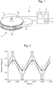
- FIG. 1 An example DC motor arrangement is schematically illustrated in Figure 1 .
- the simplified motor 1 of Figure 1 comprises a rotor 3, with permanent bipolar magnets 3b arranged on two ferromagnetic discs 3a (these magnets having an axial polarisation and alternate polarities), and a stator formed by a first stator inductor A and a second stator inductor B.
- a motor drive or control unit 5 is configured to adjust the current through the coils.
- a digital control unit 7 is in turn configured to control the operation of the motor drive unit based on a detected operation of the rotor. For instance, if the control unit 7 detects that the rotor is spinning too fast, it can order the motor drive unit 5 to slow down the rotor 3.
- the motor drive unit is also provided with a voltage supply unit 9, such as a battery.
- a measurement unit 11 for taking measurements relating to the operation of the motor.
- the resistive heating losses can be reduced if a voltage pulse generated by the motor drive unit for the stator coils is generated when the sum of the induced voltages in the stator coils is at its maximum value.
- a voltage pulse generated by the motor drive unit for the stator coils is generated when the sum of the induced voltages in the stator coils is at its maximum value.
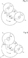
- the dashed line indicates the sum of the induced voltages in the first and second coils A, B, while the dashed step shape indicates the drive voltage pulses generated by the motor drive unit.
- the ideal situation occurs when each drive voltage pulse is centred at an absolute maximum of the sum of the two induced voltages.
- a preferred control method of a motor of the type of Figure 1 consists, within the frame of the present invention, in detecting the crossing of the two induced voltages and in triggering the drive voltage pulses by this crossing detection.
- the generated drive voltage pulses are no longer centred at absolute maxima of the sum of the induced voltages, as illustrated in Figure 3 .
- the difference between the supply voltage and the average of the sum of the induced voltage over the duration of a drive voltage pulse is no longer minimal in the situation of Figure 3 , what increases the power consumption of the motor relatively to the case of Figure 2 because of the resistive heating losses which are greater. This is thus a non-optimal situation.
- a direct current electric motor comprising:
- control unit is arranged to trigger the drive voltage pulses immediately after the detection of an equal induced voltage (i.e. detection of a crossing of the induced voltages in the two stator inductors).
- the at least one of the second inductor parameters comprises at least one structural dimension of the second inductor. Further advantageous variants are defined in dependent claims 3-11.
- the proposed solution has the advantage that the resistive heating losses can be minimised because the crossing point of the two induced voltages is located before the peak of the sum of these two induced voltages and thus the generated pulses are optimally located. In other words, the overall power consumption of the motor is minimised without however compromising the motor performance.
- an electromechanical watch comprising the motor according to the first aspect of the present invention.
- a method of operating a DC electric motor as recited in claim 12. Further preferred embodiments are defined in dependent claims 13, 14.
- the teachings of the present invention are next explained in more detail in the context of the motor of Figure 1 .
- the rotor is arranged to continuously rotate in a first direction but optionally also in a second, opposite direction.
- the first and second stator inductors or coils A, B have a disc-shaped (circular) form with a central through hole (with no magnetic material in it).
- an external diameter of each coil may be between 3 mm and 5 mm, while an internal diameter (of the central hole) may be between 0.5 mm and 1.5 mm.
- the internal diameter corresponds thus to the diameter of the central aperture.
- the inductors are in this example relatively flat and disc-shaped and have a thickness between 0.3 mm and 1 mm.
- the first and second inductors are at an angle ⁇ relative to each other.
- the angle ⁇ is here defined as the angle between a first imaginary line, passing through the axis of rotation of the rotor and the axis of rotation of the first inductor, and a second imaginary line passing through the axis of rotation of the rotor and the centre of the second inductor.
- the angle ⁇ is preferably 104° but it could instead be in an advantageous variant any value between 95° and 115° or more specifically between 100° and 110°.
- the rotor is equipped with six permanent magnets 3b, having an axial polarisation axis and alternate polarities, on each of its two ferromagnetic plates 3a and so that the angle ⁇ is 104°. This leads to an electrical phase difference of 48° between the induced voltages in the inductors.
- the present invention aims to centre drive voltage pulses time wise substantially at the respective centres of absolute maxima of the sum of the induced voltages in the two motor stator inductors by keeping the preferred motor control method characterized by providing drive voltage pulses each after a detection of a crossing of the induced voltages in the two inductors.
- it is searched the minimum between the supply voltage and the sum of the two induced voltages averaged over the pulse duration: min V bat ⁇ V ⁇ ind tot .
- This can be achieved by having asymmetrical induced voltages in the first and second inductors A, B such that each drive voltage pulse can be centred at an absolute maximum of the sum of the induced voltages.
- the present invention proposes a solution in which the two inductors A and B are no longer symmetrical or identical.
- the two inductors A and B are asymmetrical with respect to at least one inductor parameter.
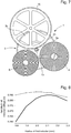
- Figure 5 schematically illustrates a rotor-stator configuration comprising two identical stator inductors. This configuration may be considered to be ideal when the two inductors are identical. However, this situation leads to a situation depicted in Figure 3 , in which the generated voltage pulse is not centred at the maximum of the sum of the induced voltages in the first and second inductors. The following notations are used:
- At least one inductor parameter of at least one of the inductors is modified compared to the situation shown in Figure 5 which defines a starting point for the configuration of the two coils according to the invention.
- the first inductor A has first inductor parameters
- the second inductor B has second inductor parameters.
- At least one of the second inductor parameters is different from at least one corresponding parameter of the first inductor parameters such that in a given rotation direction of the rotor, the rotor faces first the second inductor before facing the first inductor and such that the maximum induced voltage in the first inductor is larger than the maximum induced voltage in the second inductor.
- the measurement unit 11 is arranged to detect time instants when the induced voltage in the first inductor A equals the induced voltage in the second inductor B and to instruct the drive unit 5 accordingly.
- the drive unit 5 is arranged to trigger the voltage pulses after the detection, by the measurement unit, of an equal induced voltage in each of the first and second inductors A, B.
- the first and second inductor parameters comprise at least one of the following parameters: coil wire diameter, number of wire turns, coil thickness, coil external diameter and coil internal diameter (or the central hole), as well as and the coil position (distance of its centre or periphery from the rotation axis of the rotor).
- the inductor diameters may or may not be constant throughout the thickness of the inductor. If the coil's cross section is not substantially circular, the diameter could be replaced for instance with a largest cross-sectional dimension.
- at least one parameter which is according to the invention different between the first inductor A and the second inductor B, may be a given structural dimension of the inductors.
- Figure 6 illustrates a rotor-stator configuration, in which the external radius R A of the first inductor A has been made greater compared to the situation of Figure 5 . Furthermore, the external radius R B of the second inductor B has been made smaller, the first inductor A has been repositioned (the centre moved away from the rotor) and the second inductor B has also been repositioned (the centre moved closer to the rotor) in order to keep the parameters DAB, DAP, DBP and ⁇ substantially constant between the configurations of Figures 5 and 6 . However, it is not necessary to keep all the parameters constant when moving from the configuration of Figure 5 towards an optimal situation according to the invention. In one example configuration, DAB substantially equals DBP, which equals DAP.
- one inductor parameter of one of the inductors is altered, then this may lead to modifying at least one parameter of the other inductor.
- only one inductor parameter of one of the inductors is modified, namely one of the distances D A or D B , when moving from the configuration of Figure 5 towards the ideal situation. This means that the angle ⁇ may be kept constant when moving from the configuration of Figure 5 towards an ideal situation.
- a pinion 13 is provided at the centre of the rotor and occupies a first surface area (circular surface area) with a given diameter.
- the pinion is arranged to mesh with a wheel 15, which occupies a second surface area which is a given angular section of the surface area of the rotor (when seen from above).
- the values of the parameters D AP and D BP are greater than the radius of the pinion and that the angle ⁇ between the two inductors may have a maximal allowed value. Furthermore, a certain minimum distance may be defined between the first and second inductors A, B. Thus, in view of the above, it is possible to set minimum distances between the rotor and the first inductor on the one hand, and between the rotor and the second inductor on the other hand. Furthermore, the angle ⁇ between the two inductors may have a maximal allowed value.
- the radius of the second inductor B is kept constant and is 2.0 mm. It can be noticed that the maximum of that upper curve corresponds to a symmetrical inductor configuration, in which the two inductors have the same dimensions and are positioned at an equal distance from the rotor 3.
- the lower (thick) curve in Figure 8 shows the sum of the induced voltages averaged over the pulse duration as a function of the radius of the first inductor A. It can now be noticed that the maximum value corresponds to an asymmetrical situation, in which the first and second inductors are not identical. In this example, the external radius of the first inductor A is greater than then the external radius of the second inductor B, as also shown in Figure 6 .
- This configuration thus minimises the difference V bat ⁇ V ⁇ ind tot , where V bat is the supply voltage and V ⁇ ind tot is the average value of the sum of the induced voltages in the two inductors over a drive pulse duration.
- the peak induced voltage in the first inductor A was greater than the peak induced voltage in the second inductor B (see Fig. 4 ). Furthermore, in a given normal rotation of the rotor, a given radius reaches first the second inductor B (smaller induced voltage) and after that the first inductor A (greater induced voltage). In other words, in a normal rotation of the rotor, a given magnet of the rotor is first aligned with the second inductor and only after having rotated more (in this example counterclockwise), it becomes aligned with the first inductor.
- the crossing point of the induced voltages would be located timewise after the peak of the sum of the induced voltages. This would mean that the drive pulse to be generated would be located offset with respect to the centre of the peak of the sum of the induced voltages, what is contrary to the present invention.
- the pulse was generated substantially immediately after the crossing of the induced voltages was detected.
- a timer may be used such that the time starts to run when a voltage crossing has been detected and a pulse is triggered once the timer has expired.
- the delay may then be taken into account when designing the inductors. More specifically, the greater the delay, the more the two inductors differ from each other.
Landscapes
- Engineering & Computer Science (AREA)
- Power Engineering (AREA)
- Physics & Mathematics (AREA)
- General Physics & Mathematics (AREA)
- Electromechanical Clocks (AREA)
- Brushless Motors (AREA)
- Control Of Motors That Do Not Use Commutators (AREA)
- Control Of Stepping Motors (AREA)
Claims (14)
- Moteur électrique à courant continu (1) comprenant :• un rotor (3) pourvu d'aimants permanents, le rotor étant agencé pour tourner continuellement dans une direction de rotation déterminée ;• un premier inducteur de stator (A) ayant des premiers paramètres d'inducteur ;• un second inducteur de stator (B) ayant des seconds paramètres d'inducteur ;• une unité d'alimentation en tension (9) pour fournir une alimentation en tension aux premier et second inducteurs de stator (A, B) pour entraîner le rotor (3) ;• une unité de mesure (11) pour détecter des instants auxquels une première tension induite dans le premier inducteur de stator (A) est égale à une seconde tension induite dans le second inducteur de stator (B) ;• une unité de commande (5) pour commander l'application d'impulsions de tension d'entraînement par l'unité d'alimentation en tension (9) aux premier et second inducteurs de stator (A, B),dans lequel le rotor (3) est agencé pour faire face d'abord au second inducteur de stator (B) avant de faire face au premier inducteur de stator (A) lorsqu'il est en rotation dans la direction de rotation déterminée ;
dans lequel au moins l'un des seconds paramètres d'inducteur est différent d'un paramètre correspondant des premiers paramètres d'inducteur de sorte qu'une tension induite maximale dans le premier inducteur de stator (A) soit supérieure à une tension induite maximale dans le second inducteur de stator (B), et dans lequel l'unité de commande (5) est agencée pour déclencher chaque impulsion de tension d'entraînement après une détection, par l'unité de mesure (11), d'une tension induite égale dans chacun des premier et second inducteurs de stator (A, B). - Moteur (1) selon la revendication 1, dans lequel l'unité de commande (5) est agencée pour déclencher les impulsions de tension d'entraînement chacune immédiatement après la détection d'une tension induite égale.
- Moteur (1) selon la revendication 1 ou 2, dans lequel l'au moins un des seconds paramètres d'inducteur comprend au moins une dimension structurelle du second inducteur (B).
- Moteur (1) selon la revendication 1 ou 2, dans lequel les premier et second inducteurs sont chacun formés par une bobine, et dans lequel l'au moins un des seconds paramètres d'inducteur comprend au moins l'un des paramètres suivants : un diamètre de fil de bobine, un nombre de tours de fil, une dimension de bobine et une position de bobine radiale par rapport à un axe de rotation du rotor.
- Moteur (1) selon l'une quelconque des revendications précédentes, dans lequel une première distance définie en tant qu'une distance minimale entre un centre du rotor (3) et un bord extérieur du premier inducteur de stator (A) est sensiblement égale à une deuxième distance définie en tant qu'une distance minimale entre le centre du rotor et un bord extérieur du second inducteur de stator (B).
- Moteur selon la revendication 5, dans lequel la première distance et la deuxième distance sont sensiblement égales ou supérieures à une troisième distance définie en tant qu'une distance entre les périphéries du premier inducteur de stator (A) et du second inducteur de stator (B).
- Moteur (1) selon l'une quelconque des revendications précédentes, dans lequel l'unité de commande (5) est agencée pour appliquer les impulsions de tension d'entraînement de sorte que les impulsions de tension d'entraînement soient sensiblement centrées à un maximum absolu d'une somme des tensions induites dans les premier et second inducteurs (A, B).
- Moteur (1) selon l'une quelconque des revendications précédentes, dans lequel les premier et second inducteurs (A, B) sont à un angle α l'un par rapport à l'autre, l'angle α étant défini en tant que l'angle entre une première ligne imaginaire, passant à travers l'axe de rotation du rotor (3) et le centre du premier inducteur (A), et une seconde ligne imaginaire, passant à travers l'axe de rotation du rotor et le second inducteur (B), et dans lequel l'angle α est entre 95° et 115°.
- Moteur (1) selon l'une quelconque des revendications précédentes, dans lequel les premier et second inducteurs (A, B) sont en forme de disque de sorte que le diamètre externe de chacun des inducteurs soit plus grand que l'épaisseur de chacun des inducteurs (A, B).
- Moteur (1) selon l'une quelconque des revendications précédentes, dans lequel les premier et second inducteurs (A, B) sont raccordés dans une configuration en série au cours des impulsions de tension d'entraînement.
- Montre électromécanique comprenant le moteur (1) selon l'une quelconque des revendications précédentes.
- Procédé de fonctionnement d'un moteur électrique à courant continu (1) comprenant :• un rotor (3) pourvu d'aimants bipolaires permanents, le rotor (3) étant agencé pour tourner continuellement dans une direction de rotation déterminée ;• un premier inducteur de stator (A) ayant des premiers paramètres d'inducteur ;• un second inducteur de stator (B) ayant des seconds paramètres d'inducteur ;• une unité d'alimentation en tension (9) pour fournir une alimentation en tension aux premier et second inducteurs de stator (A, B) pour entraîner le rotor (3) ;• une unité de mesure (11) pour détecter des instants auxquels une première tension induite dans le premier inducteur de stator (A) est égale à une seconde tension induite dans le second inducteur de stator (B) ;• une unité de commande (5) pour commander l'application d'impulsions de tension d'entraînement par l'unité d'alimentation en tension (9) aux premier et second inducteurs de stator,dans lequel la rotation du rotor (3) dans la direction de rotation déterminée est prévue de sorte qu'il fasse face d'abord au second inducteur (B) avant de faire face au premier inducteur (A) ;
dans lequel au moins l'un des seconds paramètres d'inducteur est différent d'un paramètre correspondant des premiers paramètres d'inducteur de sorte qu'une tension induite maximale dans le premier inducteur de stator (A) soit supérieure à une tension induite maximale dans le second inducteur de stator (B) ; et dans lequel l'unité de commande déclenche chaque impulsion de tension d'entraînement après une détection, par l'unité de mesure, d'une tension induite égale dans chacun des premier et second inducteurs de stator (A, B). - Procédé selon la revendication 12, dans lequel les impulsions de tension d'entraînement sont déclenchées immédiatement après la détection d'une tension induite égale.
- Procédé selon la revendication 12 ou 13, dans lequel les impulsions de tension d'entraînement sont appliquées de sorte que ces impulsions de tension d'entraînement soient centrées à un maximum absolu d'une somme des tensions induites dans les premier et second inducteurs (A, B).
Priority Applications (4)
| Application Number | Priority Date | Filing Date | Title |
|---|---|---|---|
| EP18210866.2A EP3663870B1 (fr) | 2018-12-06 | 2018-12-06 | Moteur electrique à courant continu a inducteurs de stator asymetriques |
| US16/671,381 US10972027B2 (en) | 2018-12-06 | 2019-11-01 | DC electric motor with asymmetrical stator inductors |
| JP2019211078A JP6814866B2 (ja) | 2018-12-06 | 2019-11-22 | 非対称固定子誘導子を有するdc電気モータ |
| CN201911233427.5A CN111293935B (zh) | 2018-12-06 | 2019-12-05 | 直流电动机及其操作方法、电子机械手表 |
Applications Claiming Priority (1)
| Application Number | Priority Date | Filing Date | Title |
|---|---|---|---|
| EP18210866.2A EP3663870B1 (fr) | 2018-12-06 | 2018-12-06 | Moteur electrique à courant continu a inducteurs de stator asymetriques |
Publications (2)
| Publication Number | Publication Date |
|---|---|
| EP3663870A1 EP3663870A1 (fr) | 2020-06-10 |
| EP3663870B1 true EP3663870B1 (fr) | 2021-08-11 |
Family
ID=64650311
Family Applications (1)
| Application Number | Title | Priority Date | Filing Date |
|---|---|---|---|
| EP18210866.2A Active EP3663870B1 (fr) | 2018-12-06 | 2018-12-06 | Moteur electrique à courant continu a inducteurs de stator asymetriques |
Country Status (4)
| Country | Link |
|---|---|
| US (1) | US10972027B2 (fr) |
| EP (1) | EP3663870B1 (fr) |
| JP (1) | JP6814866B2 (fr) |
| CN (1) | CN111293935B (fr) |
Families Citing this family (1)
| Publication number | Priority date | Publication date | Assignee | Title |
|---|---|---|---|---|
| EP3964897B1 (fr) * | 2020-09-03 | 2024-07-03 | The Swatch Group Research and Development Ltd | Pièce d'horlogerie comprenant une génératrice et procédé de montage d'une telle piece d'horlogerie |
Family Cites Families (13)
| Publication number | Priority date | Publication date | Assignee | Title |
|---|---|---|---|---|
| CH644989GA3 (fr) | 1981-03-18 | 1984-09-14 | ||
| CH653851GA3 (en) * | 1981-03-18 | 1986-01-31 | Method of measuring voltage induced in the coil of a stepper motor by the rotation of its rotor | |
| JP2545797B2 (ja) * | 1986-05-30 | 1996-10-23 | ソニー株式会社 | ブラシレスモータ装置 |
| JPH0720374B2 (ja) * | 1987-06-01 | 1995-03-06 | 株式会社日立製作所 | インバ−タ制御装置 |
| JP2875529B2 (ja) * | 1987-10-31 | 1999-03-31 | ソニー株式会社 | センサレスブラシレスモータの駆動装置 |
| US6034502A (en) * | 1997-06-24 | 2000-03-07 | Asulab S.A. | Method for controlling a continuous rotation miniature motor |
| EP0887913B1 (fr) * | 1997-06-24 | 2012-02-29 | Asulab S.A. | Procédé de commande d'un micromoteur à rotation continue |
| GB0600837D0 (en) * | 2006-01-14 | 2006-02-22 | Alstom | Stators and electrical machines incorporating such stators |
| US7777436B2 (en) * | 2008-07-14 | 2010-08-17 | The Bergquist Torrington Company | Sensorless drive for unipolar three phase brushless DC motors |
| KR101945888B1 (ko) * | 2011-07-25 | 2019-02-11 | 아스콜 홀딩 에스.알.엘. | 영구 자석 단상 동기 전기 모터 구동 방법 및 이를 구현하는 전자 장치 |
| EP3016266A1 (fr) * | 2014-10-30 | 2016-05-04 | Siemens Schweiz AG | Mécanisme de commande doté d'un moteur à courant continu biphasé sans brosse et utilisation d'un tel moteur à courant continu |
| EP3337031B1 (fr) * | 2016-12-13 | 2020-06-17 | ABB Schweiz AG | Procédé et dispositif de détection de la présence d'un aimant permanent d'un rotor d'une machine synchrone |
| EP3339982B1 (fr) * | 2016-12-23 | 2021-08-25 | The Swatch Group Research and Development Ltd | Régulation par freinage mécanique d'un oscillateur mécanique horloger |
-
2018
- 2018-12-06 EP EP18210866.2A patent/EP3663870B1/fr active Active
-
2019
- 2019-11-01 US US16/671,381 patent/US10972027B2/en active Active
- 2019-11-22 JP JP2019211078A patent/JP6814866B2/ja active Active
- 2019-12-05 CN CN201911233427.5A patent/CN111293935B/zh active Active
Also Published As
| Publication number | Publication date |
|---|---|
| CN111293935A (zh) | 2020-06-16 |
| JP2020092589A (ja) | 2020-06-11 |
| CN111293935B (zh) | 2023-06-09 |
| US20200186064A1 (en) | 2020-06-11 |
| JP6814866B2 (ja) | 2021-01-20 |
| US10972027B2 (en) | 2021-04-06 |
| EP3663870A1 (fr) | 2020-06-10 |
Similar Documents
| Publication | Publication Date | Title |
|---|---|---|
| US9006951B2 (en) | Cogging torque reduction device for electrical machines | |
| JP4350147B2 (ja) | 電気モータ又は発電機 | |
| JP4484922B2 (ja) | 電気モータ又は発電機 | |
| US20190041804A1 (en) | Electronic watch | |
| US20130328510A1 (en) | Motor drive method, motor drive device, and brushless motor | |
| US10972027B2 (en) | DC electric motor with asymmetrical stator inductors | |
| EP1067670B1 (fr) | Méthode de réglage d'un moteur à réluctance commutée et moteur avec un faible courant de pointe | |
| US4985669A (en) | Motor feedback system | |
| JP7128798B2 (ja) | 永久磁石回転子を有する連続回転電機モータ | |
| US11063537B2 (en) | Control method of a direct current electric motor | |
| JP4402713B2 (ja) | 電気モータ又は発電機 | |
| HK40031819A (en) | A dc electric motor and a method for operating the same as well as an electromechanical watch | |
| HK40031819B (en) | A dc electric motor and a method for operating the same as well as an electromechanical watch | |
| US20100270965A1 (en) | Stepping motor control circuit and analog electronic watch | |
| EP3663871B1 (fr) | Unite d'entrainement de moteur d'un moteur electrique a courant continu | |
| JP2012065539A (ja) | ステッピングモータ制御回路及びアナログ電子時計 | |
| US20110260665A1 (en) | Positional recognition using bemf zero crossover recognition of a rotor of an electronically commutated electric machine with two coil sections of different inductances | |
| CN102035451A (zh) | 步进电机控制电路以及模拟电子钟表 | |
| HK40032032A (en) | Continuously rotating electric motor having a permanent magnet rotor | |
| HK40032032B (en) | Continuously rotating electric motor having a permanent magnet rotor | |
| JP2015152513A (ja) | 電子時計 | |
| HK40031294A (en) | Motor drive unit, operating method, and electromechanical watch of a dc electric motor | |
| HK40031294B (en) | Motor drive unit, operating method, and electromechanical watch of a dc electric motor | |
| KR20050072835A (ko) | 발전기의 전기적 출력 조절 방법 및 그 장치 | |
| HK40030030B (en) | Control method of a direct current electric motor |
Legal Events
| Date | Code | Title | Description |
|---|---|---|---|
| PUAI | Public reference made under article 153(3) epc to a published international application that has entered the european phase |
Free format text: ORIGINAL CODE: 0009012 |
|
| STAA | Information on the status of an ep patent application or granted ep patent |
Free format text: STATUS: THE APPLICATION HAS BEEN PUBLISHED |
|
| AK | Designated contracting states |
Kind code of ref document: A1 Designated state(s): AL AT BE BG CH CY CZ DE DK EE ES FI FR GB GR HR HU IE IS IT LI LT LU LV MC MK MT NL NO PL PT RO RS SE SI SK SM TR |
|
| AX | Request for extension of the european patent |
Extension state: BA ME |
|
| STAA | Information on the status of an ep patent application or granted ep patent |
Free format text: STATUS: REQUEST FOR EXAMINATION WAS MADE |
|
| 17P | Request for examination filed |
Effective date: 20201210 |
|
| RBV | Designated contracting states (corrected) |
Designated state(s): AL AT BE BG CH CY CZ DE DK EE ES FI FR GB GR HR HU IE IS IT LI LT LU LV MC MK MT NL NO PL PT RO RS SE SI SK SM TR |
|
| GRAP | Despatch of communication of intention to grant a patent |
Free format text: ORIGINAL CODE: EPIDOSNIGR1 |
|
| STAA | Information on the status of an ep patent application or granted ep patent |
Free format text: STATUS: GRANT OF PATENT IS INTENDED |
|
| INTG | Intention to grant announced |
Effective date: 20210527 |
|
| GRAS | Grant fee paid |
Free format text: ORIGINAL CODE: EPIDOSNIGR3 |
|
| GRAA | (expected) grant |
Free format text: ORIGINAL CODE: 0009210 |
|
| STAA | Information on the status of an ep patent application or granted ep patent |
Free format text: STATUS: THE PATENT HAS BEEN GRANTED |
|
| AK | Designated contracting states |
Kind code of ref document: B1 Designated state(s): AL AT BE BG CH CY CZ DE DK EE ES FI FR GB GR HR HU IE IS IT LI LT LU LV MC MK MT NL NO PL PT RO RS SE SI SK SM TR |
|
| REG | Reference to a national code |
Ref country code: CH Ref legal event code: EP |
|
| REG | Reference to a national code |
Ref country code: DE Ref legal event code: R096 Ref document number: 602018021567 Country of ref document: DE |
|
| REG | Reference to a national code |
Ref country code: IE Ref legal event code: FG4D Ref country code: AT Ref legal event code: REF Ref document number: 1419993 Country of ref document: AT Kind code of ref document: T Effective date: 20210915 |
|
| REG | Reference to a national code |
Ref country code: LT Ref legal event code: MG9D |
|
| REG | Reference to a national code |
Ref country code: NL Ref legal event code: MP Effective date: 20210811 |
|
| REG | Reference to a national code |
Ref country code: AT Ref legal event code: MK05 Ref document number: 1419993 Country of ref document: AT Kind code of ref document: T Effective date: 20210811 |
|
| PG25 | Lapsed in a contracting state [announced via postgrant information from national office to epo] |
Ref country code: SE Free format text: LAPSE BECAUSE OF FAILURE TO SUBMIT A TRANSLATION OF THE DESCRIPTION OR TO PAY THE FEE WITHIN THE PRESCRIBED TIME-LIMIT Effective date: 20210811 Ref country code: RS Free format text: LAPSE BECAUSE OF FAILURE TO SUBMIT A TRANSLATION OF THE DESCRIPTION OR TO PAY THE FEE WITHIN THE PRESCRIBED TIME-LIMIT Effective date: 20210811 Ref country code: HR Free format text: LAPSE BECAUSE OF FAILURE TO SUBMIT A TRANSLATION OF THE DESCRIPTION OR TO PAY THE FEE WITHIN THE PRESCRIBED TIME-LIMIT Effective date: 20210811 Ref country code: ES Free format text: LAPSE BECAUSE OF FAILURE TO SUBMIT A TRANSLATION OF THE DESCRIPTION OR TO PAY THE FEE WITHIN THE PRESCRIBED TIME-LIMIT Effective date: 20210811 Ref country code: FI Free format text: LAPSE BECAUSE OF FAILURE TO SUBMIT A TRANSLATION OF THE DESCRIPTION OR TO PAY THE FEE WITHIN THE PRESCRIBED TIME-LIMIT Effective date: 20210811 Ref country code: BG Free format text: LAPSE BECAUSE OF FAILURE TO SUBMIT A TRANSLATION OF THE DESCRIPTION OR TO PAY THE FEE WITHIN THE PRESCRIBED TIME-LIMIT Effective date: 20211111 Ref country code: AT Free format text: LAPSE BECAUSE OF FAILURE TO SUBMIT A TRANSLATION OF THE DESCRIPTION OR TO PAY THE FEE WITHIN THE PRESCRIBED TIME-LIMIT Effective date: 20210811 Ref country code: LT Free format text: LAPSE BECAUSE OF FAILURE TO SUBMIT A TRANSLATION OF THE DESCRIPTION OR TO PAY THE FEE WITHIN THE PRESCRIBED TIME-LIMIT Effective date: 20210811 Ref country code: NO Free format text: LAPSE BECAUSE OF FAILURE TO SUBMIT A TRANSLATION OF THE DESCRIPTION OR TO PAY THE FEE WITHIN THE PRESCRIBED TIME-LIMIT Effective date: 20211111 Ref country code: PT Free format text: LAPSE BECAUSE OF FAILURE TO SUBMIT A TRANSLATION OF THE DESCRIPTION OR TO PAY THE FEE WITHIN THE PRESCRIBED TIME-LIMIT Effective date: 20211213 |
|
| PG25 | Lapsed in a contracting state [announced via postgrant information from national office to epo] |
Ref country code: PL Free format text: LAPSE BECAUSE OF FAILURE TO SUBMIT A TRANSLATION OF THE DESCRIPTION OR TO PAY THE FEE WITHIN THE PRESCRIBED TIME-LIMIT Effective date: 20210811 Ref country code: LV Free format text: LAPSE BECAUSE OF FAILURE TO SUBMIT A TRANSLATION OF THE DESCRIPTION OR TO PAY THE FEE WITHIN THE PRESCRIBED TIME-LIMIT Effective date: 20210811 Ref country code: GR Free format text: LAPSE BECAUSE OF FAILURE TO SUBMIT A TRANSLATION OF THE DESCRIPTION OR TO PAY THE FEE WITHIN THE PRESCRIBED TIME-LIMIT Effective date: 20211112 |
|
| PG25 | Lapsed in a contracting state [announced via postgrant information from national office to epo] |
Ref country code: NL Free format text: LAPSE BECAUSE OF FAILURE TO SUBMIT A TRANSLATION OF THE DESCRIPTION OR TO PAY THE FEE WITHIN THE PRESCRIBED TIME-LIMIT Effective date: 20210811 |
|
| PG25 | Lapsed in a contracting state [announced via postgrant information from national office to epo] |
Ref country code: DK Free format text: LAPSE BECAUSE OF FAILURE TO SUBMIT A TRANSLATION OF THE DESCRIPTION OR TO PAY THE FEE WITHIN THE PRESCRIBED TIME-LIMIT Effective date: 20210811 |
|
| REG | Reference to a national code |
Ref country code: DE Ref legal event code: R097 Ref document number: 602018021567 Country of ref document: DE |
|
| PG25 | Lapsed in a contracting state [announced via postgrant information from national office to epo] |
Ref country code: SM Free format text: LAPSE BECAUSE OF FAILURE TO SUBMIT A TRANSLATION OF THE DESCRIPTION OR TO PAY THE FEE WITHIN THE PRESCRIBED TIME-LIMIT Effective date: 20210811 Ref country code: SK Free format text: LAPSE BECAUSE OF FAILURE TO SUBMIT A TRANSLATION OF THE DESCRIPTION OR TO PAY THE FEE WITHIN THE PRESCRIBED TIME-LIMIT Effective date: 20210811 Ref country code: RO Free format text: LAPSE BECAUSE OF FAILURE TO SUBMIT A TRANSLATION OF THE DESCRIPTION OR TO PAY THE FEE WITHIN THE PRESCRIBED TIME-LIMIT Effective date: 20210811 Ref country code: EE Free format text: LAPSE BECAUSE OF FAILURE TO SUBMIT A TRANSLATION OF THE DESCRIPTION OR TO PAY THE FEE WITHIN THE PRESCRIBED TIME-LIMIT Effective date: 20210811 Ref country code: CZ Free format text: LAPSE BECAUSE OF FAILURE TO SUBMIT A TRANSLATION OF THE DESCRIPTION OR TO PAY THE FEE WITHIN THE PRESCRIBED TIME-LIMIT Effective date: 20210811 Ref country code: AL Free format text: LAPSE BECAUSE OF FAILURE TO SUBMIT A TRANSLATION OF THE DESCRIPTION OR TO PAY THE FEE WITHIN THE PRESCRIBED TIME-LIMIT Effective date: 20210811 |
|
| PLBE | No opposition filed within time limit |
Free format text: ORIGINAL CODE: 0009261 |
|
| STAA | Information on the status of an ep patent application or granted ep patent |
Free format text: STATUS: NO OPPOSITION FILED WITHIN TIME LIMIT |
|
| 26N | No opposition filed |
Effective date: 20220512 |
|
| PG25 | Lapsed in a contracting state [announced via postgrant information from national office to epo] |
Ref country code: MC Free format text: LAPSE BECAUSE OF FAILURE TO SUBMIT A TRANSLATION OF THE DESCRIPTION OR TO PAY THE FEE WITHIN THE PRESCRIBED TIME-LIMIT Effective date: 20210811 Ref country code: IT Free format text: LAPSE BECAUSE OF FAILURE TO SUBMIT A TRANSLATION OF THE DESCRIPTION OR TO PAY THE FEE WITHIN THE PRESCRIBED TIME-LIMIT Effective date: 20210811 |
|
| PG25 | Lapsed in a contracting state [announced via postgrant information from national office to epo] |
Ref country code: SI Free format text: LAPSE BECAUSE OF FAILURE TO SUBMIT A TRANSLATION OF THE DESCRIPTION OR TO PAY THE FEE WITHIN THE PRESCRIBED TIME-LIMIT Effective date: 20210811 |
|
| REG | Reference to a national code |
Ref country code: BE Ref legal event code: MM Effective date: 20211231 |
|
| PG25 | Lapsed in a contracting state [announced via postgrant information from national office to epo] |
Ref country code: LU Free format text: LAPSE BECAUSE OF NON-PAYMENT OF DUE FEES Effective date: 20211206 Ref country code: IE Free format text: LAPSE BECAUSE OF NON-PAYMENT OF DUE FEES Effective date: 20211206 |
|
| PG25 | Lapsed in a contracting state [announced via postgrant information from national office to epo] |
Ref country code: BE Free format text: LAPSE BECAUSE OF NON-PAYMENT OF DUE FEES Effective date: 20211231 |
|
| PG25 | Lapsed in a contracting state [announced via postgrant information from national office to epo] |
Ref country code: CY Free format text: LAPSE BECAUSE OF FAILURE TO SUBMIT A TRANSLATION OF THE DESCRIPTION OR TO PAY THE FEE WITHIN THE PRESCRIBED TIME-LIMIT Effective date: 20210811 |
|
| P01 | Opt-out of the competence of the unified patent court (upc) registered |
Effective date: 20230615 |
|
| PG25 | Lapsed in a contracting state [announced via postgrant information from national office to epo] |
Ref country code: HU Free format text: LAPSE BECAUSE OF FAILURE TO SUBMIT A TRANSLATION OF THE DESCRIPTION OR TO PAY THE FEE WITHIN THE PRESCRIBED TIME-LIMIT; INVALID AB INITIO Effective date: 20181206 |
|
| GBPC | Gb: european patent ceased through non-payment of renewal fee |
Effective date: 20221206 |
|
| PG25 | Lapsed in a contracting state [announced via postgrant information from national office to epo] |
Ref country code: GB Free format text: LAPSE BECAUSE OF NON-PAYMENT OF DUE FEES Effective date: 20221206 |
|
| PG25 | Lapsed in a contracting state [announced via postgrant information from national office to epo] |
Ref country code: MK Free format text: LAPSE BECAUSE OF FAILURE TO SUBMIT A TRANSLATION OF THE DESCRIPTION OR TO PAY THE FEE WITHIN THE PRESCRIBED TIME-LIMIT Effective date: 20210811 |
|
| PG25 | Lapsed in a contracting state [announced via postgrant information from national office to epo] |
Ref country code: TR Free format text: LAPSE BECAUSE OF FAILURE TO SUBMIT A TRANSLATION OF THE DESCRIPTION OR TO PAY THE FEE WITHIN THE PRESCRIBED TIME-LIMIT Effective date: 20210811 |
|
| PG25 | Lapsed in a contracting state [announced via postgrant information from national office to epo] |
Ref country code: MT Free format text: LAPSE BECAUSE OF FAILURE TO SUBMIT A TRANSLATION OF THE DESCRIPTION OR TO PAY THE FEE WITHIN THE PRESCRIBED TIME-LIMIT Effective date: 20210811 |
|
| REG | Reference to a national code |
Ref country code: CH Ref legal event code: U11 Free format text: ST27 STATUS EVENT CODE: U-0-0-U10-U11 (AS PROVIDED BY THE NATIONAL OFFICE) Effective date: 20260101 |
|
| PGFP | Annual fee paid to national office [announced via postgrant information from national office to epo] |
Ref country code: DE Payment date: 20251126 Year of fee payment: 8 |
|
| PGFP | Annual fee paid to national office [announced via postgrant information from national office to epo] |
Ref country code: FR Payment date: 20251120 Year of fee payment: 8 |
|
| PGFP | Annual fee paid to national office [announced via postgrant information from national office to epo] |
Ref country code: CH Payment date: 20260101 Year of fee payment: 8 |