EP3663889B1 - Élément d'étanchéité pour dispositifs de cuisson commandés par bouton - Google Patents
Élément d'étanchéité pour dispositifs de cuisson commandés par bouton Download PDFInfo
- Publication number
- EP3663889B1 EP3663889B1 EP19207770.9A EP19207770A EP3663889B1 EP 3663889 B1 EP3663889 B1 EP 3663889B1 EP 19207770 A EP19207770 A EP 19207770A EP 3663889 B1 EP3663889 B1 EP 3663889B1
- Authority
- EP
- European Patent Office
- Prior art keywords
- sealing element
- plate
- hole
- upper flange
- button
- Prior art date
- Legal status (The legal status is an assumption and is not a legal conclusion. Google has not performed a legal analysis and makes no representation as to the accuracy of the status listed.)
- Not-in-force
Links
Images


Classifications
-
- G—PHYSICS
- G05—CONTROLLING; REGULATING
- G05G—CONTROL DEVICES OR SYSTEMS INSOFAR AS CHARACTERISED BY MECHANICAL FEATURES ONLY
- G05G25/00—Other details or appurtenances of control mechanisms, e.g. supporting intermediate members elastically
- G05G25/04—Sealing against entry of dust, weather or the like
-
- F—MECHANICAL ENGINEERING; LIGHTING; HEATING; WEAPONS; BLASTING
- F24—HEATING; RANGES; VENTILATING
- F24C—DOMESTIC STOVES OR RANGES ; DETAILS OF DOMESTIC STOVES OR RANGES, OF GENERAL APPLICATION
- F24C3/00—Stoves or ranges for gaseous fuels
- F24C3/12—Arrangement or mounting of control or safety devices
- F24C3/126—Arrangement or mounting of control or safety devices on ranges
-
- F—MECHANICAL ENGINEERING; LIGHTING; HEATING; WEAPONS; BLASTING
- F24—HEATING; RANGES; VENTILATING
- F24C—DOMESTIC STOVES OR RANGES ; DETAILS OF DOMESTIC STOVES OR RANGES, OF GENERAL APPLICATION
- F24C7/00—Stoves or ranges heated by electric energy
- F24C7/08—Arrangement or mounting of control or safety devices
- F24C7/082—Arrangement or mounting of control or safety devices on ranges, e.g. control panels, illumination
Definitions
- the present invention relates to a sealing element which is suitable for use in button-controlled cooking devices, especially cooktops, and provides liquid sealing at openings of control elements which are located on a plate of the cooktop.
- Gas and/or electric heaters are used in cooking devices (especially in cooktops) that are used for cooking foods. Such heaters are controlled by at least one button and, preferably, by a control element which is connected with the button. While using the cooking device, a part or liquid part of the food may spill onto the button from a pan or kitchen utensils as spoons, ladles or plates. In this case, if exposed parts of the hole for accessing the control element that is connected with the button are sealed with a sealing element, parts or liquid parts of the food are prevented from leaking into the product.
- a sealing element according to the invention is suitable to use, in a cooking device comprising at least one plate suitable for positioning a cooking vessel thereon for cooking process; at least one heater providing heat to the cooking vessel for the cooking process; at least one button for controlling the cooking process; and at least one hole provided on the plate for receiving the button; for prevention of leakage of a part and/or liquid part of foods through the hole upon being positioned at the hole, wherein the sealing element comprises at least one body which has at least one opening extending longitudinally therein and at least one wall extending around the opening; at least one upper flange located at a first side of the body so that at least a side of the upper flange is connected with the wall, having at least a first width which extends away from the wall in a horizontal plane, and suitable for being placed on an upper surface of the plate which is provided at a part thereof intersecting with the hole; and at least one lower flange which is suitable for being placed on a lower surface of the plate provided at a part thereof intersecting with the hole, which is located at
- the sealing element according to the present invention With the sealing element according to the present invention, a part and/or liquid part of foods are prevented from leaking through the hole provided on the plate in the button-controlled cooking devices. Thanks to the structure of the sealing element, wear and/or tear risks are minimised during processes of insertion into and removal from the hole which is provided at the plate of the cooktop. Therefore, an easy-to-use, practical and reliable sealing element is achieved.
- An object of the present invention is to provide a sealing element for button-controlled cooking devices, especially for cooktops.
- Another object of the present invention is to provide a sealing element which is located at the plate of the cooking device and provides sealing at the holes in which the button is located.
- a further object of the present invention is to provide a sealing element which is located at the plate of the cooking device and prevents problems as wear or tear during insertion and removal of the button into and from the holes where it is located.
- Yet another object of the present invention is to provide an easy-to-assemble, practical and reliable sealing element.
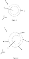
- Sealing element S
- T Body (1) Opening (1a) Upper flange (2) Lower flange (3) First part (3a) Second part (3b) Third part (3c) Wall (4) Protrusion (5)
- Gas and/or electric heaters provided in cooking devices which are used for cooking foods are controlled by at least one button and preferably a control panel which is connected with the button.
- the button is located at the holes so that it is preferably connected with the control panel, wherein the holes are provided on the plate of the cooking device. Exposed parts of the hole in which the button is located are sealed by means of a sealing element to prevent parts or liquid parts of the food from reaching the control panel.
- a sealing element to prevent parts or liquid parts of the food from reaching the control panel.
- the sealing element (S) comprises at least one body (1) which has at least one opening (1a) extending longitudinally therein and having a circular or oval cross sectional area and at least one wall (4) extending around the opening (1a) (e.g.
- At least one upper flange (2) located at a first side of the body (1) so that at least a side of the upper flange (2) is connected with the wall (4), having at least a first width which extends away from the wall (4) in a horizontal plane (e.g.
- the lower flange (3) comprises at least a first part (3a) in the form of an arc section having at least a first width in the horizontal plane (in other words, preferably having an equal width with the upper flange (2)), at least a second part (3b) in the form of an arc section located opposite to the first part (3a) and having at least a second width in the horizontal plane that is larger than the first width, and at least a third part (3c) which couples opposing ends of the first part (3a) and the second part (3b).
- the button in the cooktops which can be controlled by a button, is preferably located at the end parts of the control element which are exposed by the holes provided on the plate (T) of the cooking device such that a distance is provided between the plate (T) of the cooktop and the button, and at least a part of the button extends through the hole into the cooking device.
- the sealing element (S) which is inserted into the holes and preferably produced as a monolithic structure covers the distance between the button and the plate (T) of the cooktop so that the parts or liquid parts of the food are prevented from leaking through the hole and reaching the lower part of the plate (T) (e.g. a control panel provided at this lower part).
- the sealing element (S) is passed through the hole by bending the lower flange (3) preferably from an area where the second part (3b) and the third part (3c) forming the outer wall thereof engages such that the upper flange (2) preferably having a circular cross sectional area (in other words, e.g. in the form of a ring) is at the upper surface of the plate (T) which is provided at a part thereof intersecting with the hole.
- the upper surface of the lower flange (3) is placed at the lower surface of the plate (T) provided at a part intersecting with the hole.
- the lower flange (3) and the upper flange (2) form a channel structure and the parts of the plate (T) intersecting with the hole is fixed in that channel.
- the wall (4) forming the body of the sealing element (S) covers the gap which is to be formed due to the distance between the button and the plate (T) of the cooktop. Therefore, when the parts and/or liquid parts of the food are spilled onto the part where the hole is provided, the parts and/or the liquid parts which have been spilled are effectively prevented from leaking through hole and reaching the lower part of the plate (T). In addition, thanks to such a channel structure, the parts and/or liquid parts of the food are able to be prevented from reaching the lower flange (3) even if the parts and/or liquid parts of the food leak through the upper flange (2).
- the sealing element (S) according to the invention is preferably made of silicon material.
- the lower flange (3) easily stretches when it is bent for inserting the sealing element (S) into the hole provided on the plate (T), and passes through the hole without wearing or tearing.
- the sealing element (S) comprises at least one protrusion (5) which is provided at a side of the outer edge of the upper flange (2) corresponding to the first part (3a) (preferably provided at the middle of the side of the outer edge of the upper flange (2) corresponding to the first side (3a)), which, preferably, has a narrowing structure away from the center of the opening (1a), and which indicates the direction that the lower flange (3) is removed out of the plate (T) (in other words, the direction that indicates the first part (3a) of the lower flange (3)).
- the sealing element (S) is required to be removed out of the hole, the sealing element (S) is removed after being pulled from the side where the protrusion (5) is provided. Therefore, the sealing element (S) is removed out of the hole without being deformed.
- arc section form of the first part (3a) of the sealing element (S) according to the invention has an elliptical section or a circle section form.
- arc section form of the second part (3b) of the sealing element (S) according to the invention has an elliptical section or a circle section form.
- the third part (3c) of the sealing element (S) is a part which has a flat form, which passes along at least one side of the first part (3a) (preferably passing along at least one end of the first side (3a)), and which corresponds to a part remaining in between a point of at least one tangent line where the tangent line contacts the first part (3a) and a point thereof intersecting with an end of the second part (3b) (the end of the second part (3b) is the end which is close to the tangent line or the opposite end thereof where the tangent line passes).
- the lower flange (3) is easily bent by the person who inserts the sealing element (S), thereby achieving a sealing element (S) which can be easily inserted and removed.
- the body (1) may have a cylindrical form in a preferred embodiment of the invention
- the body (1) in another preferred embodiment of the invention, has preferably a truncated cone form whose surface area of the base connected with the upper flange (2) is smaller than the surface are of the other base.
- sealing element (S) With the sealing element (S) according to the present invention, a part and/or liquid part of foods are prevented from leaking through the hole provided on the plate (T) in the button-controlled cooking devices. Thanks to the structure of the sealing element (S), wear and/or tear risks are minimised during processes of insertion into and removal from the hole which is provided at the plate of the cooktop. Therefore, an easy-to-use, practical and reliable sealing element (S) is achieved.
Landscapes
- Engineering & Computer Science (AREA)
- Chemical & Material Sciences (AREA)
- Combustion & Propulsion (AREA)
- Mechanical Engineering (AREA)
- General Engineering & Computer Science (AREA)
- Physics & Mathematics (AREA)
- General Physics & Mathematics (AREA)
- Automation & Control Theory (AREA)
- Cookers (AREA)
- Baking, Grill, Roasting (AREA)
Claims (15)
- Élément d'étanchéité (S) qui est approprié pour une utilisation dans un dispositif de cuisson comprenant au moins une plaque (T) appropriée pour positionner un récipient de cuisson sur celle-ci pour un processus de cuisson ; au moins un dispositif de chauffage fournissant de la chaleur au récipient de cuisson pour le processus de cuisson ; au moins un bouton pour commander le processus de cuisson ; et au moins un trou prévu sur la plaque (T) pour recevoir le bouton ; pour empêcher une fuite d'une partie et/ou d'une partie liquide d'aliments à travers le trou lorsqu'il est positionné au niveau du trou, dans lequel l'élément d'étanchéité (S) comprend- au moins un corps (1) qui présente au moins une ouverture (1a) s'étendant longitudinalement dans celui-ci et au moins une paroi (4) s'étendant autour de l'ouverture (1a) ;- au moins une bride supérieure (2) située sur un premier côté du corps (1) de sorte qu'au moins un côté de la bride supérieure (2) est relié à la paroi (4), ayant au moins une première largeur qui s'étend à partir de la paroi (4) dans un plan horizontal, et appropriée pour être placée sur une surface supérieure de la plaque (T) qui est prévue sur une partie de celle-ci coupant le trou ;l'élément d'étanchéité (S) caractérisé en ce qu'il comprend- au moins une bride inférieure (3) qui est appropriée pour être placée sur une surface inférieure de la plaque (T) prévue au niveau d'une partie de celle-ci coupant le trou, qui est située au niveau du premier côté du corps (1) en dessous de la bride supérieure (2) de sorte qu'au moins un côté de la bride inférieure (2) est relié à la paroi (4), et qui comprend• au moins une première partie (3a) sous la forme d'une section en arc ayant au moins une première largeur dans le plan horizontal,• au moins une deuxième partie (3b) en forme de section en arc située à l'opposé de la première partie (3a) et ayant au moins une deuxième largeur dans le plan horizontal qui est plus grande que la première largeur, et• au moins une troisième partie (3c) qui couple les extrémités opposées de la première partie (3a) et de la deuxième partie (3b).
- Élément d'étanchéité (S) selon la revendication 1, caractérisé en ce qu'il comprend au moins une saillie (5) qui est prévue sur un côté du bord extérieur de la bride supérieure (2) correspondant à la première partie (3a) et indique la direction dans laquelle la bride inférieure (3) est retirée de la plaque (T).
- Élément d'étanchéité (S) selon la revendication 2, caractérisé en ce que la saillie (5) présente une structure de rétrécissement à partir du centre de l'ouverture (1a).
- Élément d'étanchéité (S) selon la revendication 1, caractérisé en ce que la forme de section en arc de la première partie (3a) présente une forme de section elliptique.
- Élément d'étanchéité (S) selon la revendication 1, caractérisé en ce que la forme de section en arc de la première partie (3a) présente une forme de section circulaire.
- Élément d'étanchéité (S) selon la revendication 1, caractérisé en ce que la forme de section en arc de la deuxième partie (3b) présente une forme de section elliptique.
- Élément d'étanchéité (S) selon la revendication 1, caractérisé en ce que la forme de section en arc de la deuxième partie (3b) présente une forme de section circulaire.
- Élément d'étanchéité (S) selon la revendication 1, caractérisé en ce que la troisième partie (3c) est une partie qui présente une forme plate et correspond à une partie restante entre un point d'au moins une ligne tangente où la ligne tangente est en contact avec la première partie (3a) et un point de celle-ci coupant une extrémité de la deuxième partie (3b), dans lequel la ligne tangente passe le long d'au moins un côté de la première partie (3a).
- Élément d'étanchéité (S) selon la revendication 1, caractérisé en ce que le corps (1) présente une forme cylindrique.
- Élément d'étanchéité (S) selon la revendication 1, caractérisé en ce que le corps (1) présente une forme tronconique.
- Élément d'étanchéité (S) selon la revendication 1, caractérisé en ce que le corps (1) présente une forme tronconique dont la superficie de la base reliée à la bride supérieure (2) est inférieure à la superficie de l'autre base.
- Élément d'étanchéité (S) selon la revendication 1, caractérisé en ce que la bride supérieure (2) présente une section transversale circulaire.
- Élément d'étanchéité (S) selon la revendication 1, caractérisé en ce que l'ouverture (1a) présente une section transversale circulaire ou ovale.
- Élément d'étanchéité (S) selon la revendication 1, caractérisé en ce que la première partie (3a) présente une largeur égale à celle de la bride supérieure (2).
- Élément d'étanchéité (S) selon l'une quelconque des revendications précédentes, caractérisé en ce que l'élément d'étanchéité (S) est réalisé en matériau silicone.
Applications Claiming Priority (1)
| Application Number | Priority Date | Filing Date | Title |
|---|---|---|---|
| TR2018/17651A TR201817651A2 (tr) | 2018-11-22 | 2018-11-22 | Düğme kontrollü pişirici cihazlar için bir sızdırmazlık elemanı. |
Publications (2)
| Publication Number | Publication Date |
|---|---|
| EP3663889A1 EP3663889A1 (fr) | 2020-06-10 |
| EP3663889B1 true EP3663889B1 (fr) | 2021-10-13 |
Family
ID=68609867
Family Applications (1)
| Application Number | Title | Priority Date | Filing Date |
|---|---|---|---|
| EP19207770.9A Not-in-force EP3663889B1 (fr) | 2018-11-22 | 2019-11-07 | Élément d'étanchéité pour dispositifs de cuisson commandés par bouton |
Country Status (3)
| Country | Link |
|---|---|
| EP (1) | EP3663889B1 (fr) |
| ES (1) | ES2901397T3 (fr) |
| TR (1) | TR201817651A2 (fr) |
Families Citing this family (1)
| Publication number | Priority date | Publication date | Assignee | Title |
|---|---|---|---|---|
| EP3933272B1 (fr) * | 2020-06-30 | 2023-08-30 | BSH Hausgeräte GmbH | Cuisinière à gaz |
Family Cites Families (2)
| Publication number | Priority date | Publication date | Assignee | Title |
|---|---|---|---|---|
| TR200502100A2 (tr) * | 2005-06-03 | 2007-01-22 | Bsh Ev Aletler� Sanay� Ve T�Caret Anon�M ��Rket�@ | P |
| CN104075357B (zh) * | 2013-03-26 | 2018-01-09 | 博西华电器(江苏)有限公司 | 燃气灶操作装置的防水结构及燃气灶 |
-
2018
- 2018-11-22 TR TR2018/17651A patent/TR201817651A2/tr unknown
-
2019
- 2019-11-07 ES ES19207770T patent/ES2901397T3/es active Active
- 2019-11-07 EP EP19207770.9A patent/EP3663889B1/fr not_active Not-in-force
Also Published As
| Publication number | Publication date |
|---|---|
| EP3663889A1 (fr) | 2020-06-10 |
| TR201817651A2 (tr) | 2020-06-22 |
| ES2901397T3 (es) | 2022-03-22 |
Similar Documents
| Publication | Publication Date | Title |
|---|---|---|
| US8707946B2 (en) | Household appliance, in particular a kitchen range | |
| EP3663889B1 (fr) | Élément d'étanchéité pour dispositifs de cuisson commandés par bouton | |
| US4132239A (en) | Fluid valve for microwave devices | |
| JPH0311373B2 (fr) | ||
| EP3933272B1 (fr) | Cuisinière à gaz | |
| KR200488476Y1 (ko) | 가스레인지용 단열 링 | |
| CN107440528B (zh) | 密封件、盖体和烹饪器具 | |
| US10712015B2 (en) | Grommet for cook top | |
| EP2110608A1 (fr) | Plaque de cuisson et cadre stylique pour plaque de cuisson | |
| EP1683452B1 (fr) | Bouilloire | |
| US2561474A (en) | Coordinated electric heater and thermostat mounting | |
| CN110068028B (zh) | 烹调装置 | |
| CN215686749U (zh) | 盖体及具有其的烹饪器具 | |
| EP2451322B1 (fr) | Autocuiseur pourvu d'un dispositif de sécurité supplémentaire contre le danger d'explosion dû à la surpression | |
| JP4520592B2 (ja) | ガスコンロ | |
| EP3182019B1 (fr) | Appareil de cuisson ayant un élément de couplage | |
| KR102492361B1 (ko) | 전기압력밥솥 | |
| KR101218638B1 (ko) | 전기조리기 및 그의 제조방법 | |
| EP2798276B1 (fr) | Cuisinière | |
| KR20090011933U (ko) | 전자레인지용 조리기 커버구조 | |
| KR200315425Y1 (ko) | 압력솥의 몸체구조 | |
| EP4042072B1 (fr) | Cuisinière à gaz | |
| TR2023010635A1 (tr) | Pi̇şi̇ri̇ci̇ ci̇hazda kullanilmaya uygun bi̇r düğme | |
| CN116802436A (zh) | 具有固定元件的烹饪装置 | |
| KR102059061B1 (ko) | 가스기구의 상판 유닛 |
Legal Events
| Date | Code | Title | Description |
|---|---|---|---|
| PUAI | Public reference made under article 153(3) epc to a published international application that has entered the european phase |
Free format text: ORIGINAL CODE: 0009012 |
|
| STAA | Information on the status of an ep patent application or granted ep patent |
Free format text: STATUS: THE APPLICATION HAS BEEN PUBLISHED |
|
| AK | Designated contracting states |
Kind code of ref document: A1 Designated state(s): AL AT BE BG CH CY CZ DE DK EE ES FI FR GB GR HR HU IE IS IT LI LT LU LV MC MK MT NL NO PL PT RO RS SE SI SK SM TR |
|
| AX | Request for extension of the european patent |
Extension state: BA ME |
|
| STAA | Information on the status of an ep patent application or granted ep patent |
Free format text: STATUS: REQUEST FOR EXAMINATION WAS MADE |
|
| 17P | Request for examination filed |
Effective date: 20201201 |
|
| RBV | Designated contracting states (corrected) |
Designated state(s): AL AT BE BG CH CY CZ DE DK EE ES FI FR GB GR HR HU IE IS IT LI LT LU LV MC MK MT NL NO PL PT RO RS SE SI SK SM TR |
|
| GRAP | Despatch of communication of intention to grant a patent |
Free format text: ORIGINAL CODE: EPIDOSNIGR1 |
|
| STAA | Information on the status of an ep patent application or granted ep patent |
Free format text: STATUS: GRANT OF PATENT IS INTENDED |
|
| INTG | Intention to grant announced |
Effective date: 20210611 |
|
| INTG | Intention to grant announced |
Effective date: 20210618 |
|
| INTG | Intention to grant announced |
Effective date: 20210624 |
|
| GRAS | Grant fee paid |
Free format text: ORIGINAL CODE: EPIDOSNIGR3 |
|
| GRAA | (expected) grant |
Free format text: ORIGINAL CODE: 0009210 |
|
| STAA | Information on the status of an ep patent application or granted ep patent |
Free format text: STATUS: THE PATENT HAS BEEN GRANTED |
|
| AK | Designated contracting states |
Kind code of ref document: B1 Designated state(s): AL AT BE BG CH CY CZ DE DK EE ES FI FR GB GR HR HU IE IS IT LI LT LU LV MC MK MT NL NO PL PT RO RS SE SI SK SM TR |
|
| REG | Reference to a national code |
Ref country code: GB Ref legal event code: FG4D |
|
| REG | Reference to a national code |
Ref country code: CH Ref legal event code: EP |
|
| REG | Reference to a national code |
Ref country code: DE Ref legal event code: R096 Ref document number: 602019008313 Country of ref document: DE |
|
| REG | Reference to a national code |
Ref country code: IE Ref legal event code: FG4D |
|
| REG | Reference to a national code |
Ref country code: AT Ref legal event code: REF Ref document number: 1438638 Country of ref document: AT Kind code of ref document: T Effective date: 20211115 |
|
| REG | Reference to a national code |
Ref country code: LT Ref legal event code: MG9D |
|
| REG | Reference to a national code |
Ref country code: NL Ref legal event code: MP Effective date: 20211013 |
|
| REG | Reference to a national code |
Ref country code: AT Ref legal event code: MK05 Ref document number: 1438638 Country of ref document: AT Kind code of ref document: T Effective date: 20211013 |
|
| REG | Reference to a national code |
Ref country code: ES Ref legal event code: FG2A Ref document number: 2901397 Country of ref document: ES Kind code of ref document: T3 Effective date: 20220322 |
|
| PG25 | Lapsed in a contracting state [announced via postgrant information from national office to epo] |
Ref country code: RS Free format text: LAPSE BECAUSE OF FAILURE TO SUBMIT A TRANSLATION OF THE DESCRIPTION OR TO PAY THE FEE WITHIN THE PRESCRIBED TIME-LIMIT Effective date: 20211013 Ref country code: LT Free format text: LAPSE BECAUSE OF FAILURE TO SUBMIT A TRANSLATION OF THE DESCRIPTION OR TO PAY THE FEE WITHIN THE PRESCRIBED TIME-LIMIT Effective date: 20211013 Ref country code: FI Free format text: LAPSE BECAUSE OF FAILURE TO SUBMIT A TRANSLATION OF THE DESCRIPTION OR TO PAY THE FEE WITHIN THE PRESCRIBED TIME-LIMIT Effective date: 20211013 Ref country code: BG Free format text: LAPSE BECAUSE OF FAILURE TO SUBMIT A TRANSLATION OF THE DESCRIPTION OR TO PAY THE FEE WITHIN THE PRESCRIBED TIME-LIMIT Effective date: 20220113 Ref country code: AT Free format text: LAPSE BECAUSE OF FAILURE TO SUBMIT A TRANSLATION OF THE DESCRIPTION OR TO PAY THE FEE WITHIN THE PRESCRIBED TIME-LIMIT Effective date: 20211013 |
|
| PG25 | Lapsed in a contracting state [announced via postgrant information from national office to epo] |
Ref country code: IS Free format text: LAPSE BECAUSE OF FAILURE TO SUBMIT A TRANSLATION OF THE DESCRIPTION OR TO PAY THE FEE WITHIN THE PRESCRIBED TIME-LIMIT Effective date: 20220213 Ref country code: SE Free format text: LAPSE BECAUSE OF FAILURE TO SUBMIT A TRANSLATION OF THE DESCRIPTION OR TO PAY THE FEE WITHIN THE PRESCRIBED TIME-LIMIT Effective date: 20211013 Ref country code: PT Free format text: LAPSE BECAUSE OF FAILURE TO SUBMIT A TRANSLATION OF THE DESCRIPTION OR TO PAY THE FEE WITHIN THE PRESCRIBED TIME-LIMIT Effective date: 20220214 Ref country code: PL Free format text: LAPSE BECAUSE OF FAILURE TO SUBMIT A TRANSLATION OF THE DESCRIPTION OR TO PAY THE FEE WITHIN THE PRESCRIBED TIME-LIMIT Effective date: 20211013 Ref country code: NO Free format text: LAPSE BECAUSE OF FAILURE TO SUBMIT A TRANSLATION OF THE DESCRIPTION OR TO PAY THE FEE WITHIN THE PRESCRIBED TIME-LIMIT Effective date: 20220113 Ref country code: NL Free format text: LAPSE BECAUSE OF FAILURE TO SUBMIT A TRANSLATION OF THE DESCRIPTION OR TO PAY THE FEE WITHIN THE PRESCRIBED TIME-LIMIT Effective date: 20211013 Ref country code: LV Free format text: LAPSE BECAUSE OF FAILURE TO SUBMIT A TRANSLATION OF THE DESCRIPTION OR TO PAY THE FEE WITHIN THE PRESCRIBED TIME-LIMIT Effective date: 20211013 Ref country code: HR Free format text: LAPSE BECAUSE OF FAILURE TO SUBMIT A TRANSLATION OF THE DESCRIPTION OR TO PAY THE FEE WITHIN THE PRESCRIBED TIME-LIMIT Effective date: 20211013 Ref country code: GR Free format text: LAPSE BECAUSE OF FAILURE TO SUBMIT A TRANSLATION OF THE DESCRIPTION OR TO PAY THE FEE WITHIN THE PRESCRIBED TIME-LIMIT Effective date: 20220114 |
|
| REG | Reference to a national code |
Ref country code: DE Ref legal event code: R119 Ref document number: 602019008313 Country of ref document: DE |
|
| PG25 | Lapsed in a contracting state [announced via postgrant information from national office to epo] |
Ref country code: SM Free format text: LAPSE BECAUSE OF FAILURE TO SUBMIT A TRANSLATION OF THE DESCRIPTION OR TO PAY THE FEE WITHIN THE PRESCRIBED TIME-LIMIT Effective date: 20211013 Ref country code: SK Free format text: LAPSE BECAUSE OF FAILURE TO SUBMIT A TRANSLATION OF THE DESCRIPTION OR TO PAY THE FEE WITHIN THE PRESCRIBED TIME-LIMIT Effective date: 20211013 Ref country code: RO Free format text: LAPSE BECAUSE OF FAILURE TO SUBMIT A TRANSLATION OF THE DESCRIPTION OR TO PAY THE FEE WITHIN THE PRESCRIBED TIME-LIMIT Effective date: 20211013 Ref country code: MC Free format text: LAPSE BECAUSE OF FAILURE TO SUBMIT A TRANSLATION OF THE DESCRIPTION OR TO PAY THE FEE WITHIN THE PRESCRIBED TIME-LIMIT Effective date: 20211013 Ref country code: LU Free format text: LAPSE BECAUSE OF NON-PAYMENT OF DUE FEES Effective date: 20211107 Ref country code: EE Free format text: LAPSE BECAUSE OF FAILURE TO SUBMIT A TRANSLATION OF THE DESCRIPTION OR TO PAY THE FEE WITHIN THE PRESCRIBED TIME-LIMIT Effective date: 20211013 Ref country code: DK Free format text: LAPSE BECAUSE OF FAILURE TO SUBMIT A TRANSLATION OF THE DESCRIPTION OR TO PAY THE FEE WITHIN THE PRESCRIBED TIME-LIMIT Effective date: 20211013 Ref country code: CZ Free format text: LAPSE BECAUSE OF FAILURE TO SUBMIT A TRANSLATION OF THE DESCRIPTION OR TO PAY THE FEE WITHIN THE PRESCRIBED TIME-LIMIT Effective date: 20211013 Ref country code: BE Free format text: LAPSE BECAUSE OF NON-PAYMENT OF DUE FEES Effective date: 20211130 |
|
| REG | Reference to a national code |
Ref country code: BE Ref legal event code: MM Effective date: 20211130 |
|
| PLBE | No opposition filed within time limit |
Free format text: ORIGINAL CODE: 0009261 |
|
| STAA | Information on the status of an ep patent application or granted ep patent |
Free format text: STATUS: NO OPPOSITION FILED WITHIN TIME LIMIT |
|
| 26N | No opposition filed |
Effective date: 20220714 |
|
| PG25 | Lapsed in a contracting state [announced via postgrant information from national office to epo] |
Ref country code: IE Free format text: LAPSE BECAUSE OF NON-PAYMENT OF DUE FEES Effective date: 20211107 Ref country code: DE Free format text: LAPSE BECAUSE OF NON-PAYMENT OF DUE FEES Effective date: 20220601 Ref country code: AL Free format text: LAPSE BECAUSE OF FAILURE TO SUBMIT A TRANSLATION OF THE DESCRIPTION OR TO PAY THE FEE WITHIN THE PRESCRIBED TIME-LIMIT Effective date: 20211013 |
|
| PG25 | Lapsed in a contracting state [announced via postgrant information from national office to epo] |
Ref country code: SI Free format text: LAPSE BECAUSE OF FAILURE TO SUBMIT A TRANSLATION OF THE DESCRIPTION OR TO PAY THE FEE WITHIN THE PRESCRIBED TIME-LIMIT Effective date: 20211013 |
|
| PGFP | Annual fee paid to national office [announced via postgrant information from national office to epo] |
Ref country code: ES Payment date: 20230125 Year of fee payment: 4 |
|
| PG25 | Lapsed in a contracting state [announced via postgrant information from national office to epo] |
Ref country code: CY Free format text: LAPSE BECAUSE OF FAILURE TO SUBMIT A TRANSLATION OF THE DESCRIPTION OR TO PAY THE FEE WITHIN THE PRESCRIBED TIME-LIMIT Effective date: 20211013 |
|
| REG | Reference to a national code |
Ref country code: CH Ref legal event code: PL |
|
| PG25 | Lapsed in a contracting state [announced via postgrant information from national office to epo] |
Ref country code: LI Free format text: LAPSE BECAUSE OF NON-PAYMENT OF DUE FEES Effective date: 20221130 Ref country code: HU Free format text: LAPSE BECAUSE OF FAILURE TO SUBMIT A TRANSLATION OF THE DESCRIPTION OR TO PAY THE FEE WITHIN THE PRESCRIBED TIME-LIMIT; INVALID AB INITIO Effective date: 20191107 Ref country code: CH Free format text: LAPSE BECAUSE OF NON-PAYMENT OF DUE FEES Effective date: 20221130 |
|
| PGFP | Annual fee paid to national office [announced via postgrant information from national office to epo] |
Ref country code: GB Payment date: 20231123 Year of fee payment: 5 |
|
| PGFP | Annual fee paid to national office [announced via postgrant information from national office to epo] |
Ref country code: IT Payment date: 20231124 Year of fee payment: 5 Ref country code: FR Payment date: 20231120 Year of fee payment: 5 |
|
| PG25 | Lapsed in a contracting state [announced via postgrant information from national office to epo] |
Ref country code: MK Free format text: LAPSE BECAUSE OF FAILURE TO SUBMIT A TRANSLATION OF THE DESCRIPTION OR TO PAY THE FEE WITHIN THE PRESCRIBED TIME-LIMIT Effective date: 20211013 |
|
| PG25 | Lapsed in a contracting state [announced via postgrant information from national office to epo] |
Ref country code: MT Free format text: LAPSE BECAUSE OF FAILURE TO SUBMIT A TRANSLATION OF THE DESCRIPTION OR TO PAY THE FEE WITHIN THE PRESCRIBED TIME-LIMIT Effective date: 20211013 |
|
| REG | Reference to a national code |
Ref country code: ES Ref legal event code: FD2A Effective date: 20241230 |
|
| PG25 | Lapsed in a contracting state [announced via postgrant information from national office to epo] |
Ref country code: ES Free format text: LAPSE BECAUSE OF NON-PAYMENT OF DUE FEES Effective date: 20231108 |
|
| PG25 | Lapsed in a contracting state [announced via postgrant information from national office to epo] |
Ref country code: ES Free format text: LAPSE BECAUSE OF NON-PAYMENT OF DUE FEES Effective date: 20231108 |
|
| GBPC | Gb: european patent ceased through non-payment of renewal fee |
Effective date: 20241107 |
|
| PG25 | Lapsed in a contracting state [announced via postgrant information from national office to epo] |
Ref country code: IT Free format text: LAPSE BECAUSE OF NON-PAYMENT OF DUE FEES Effective date: 20241107 |
|
| PG25 | Lapsed in a contracting state [announced via postgrant information from national office to epo] |
Ref country code: GB Free format text: LAPSE BECAUSE OF NON-PAYMENT OF DUE FEES Effective date: 20241107 |
|
| PG25 | Lapsed in a contracting state [announced via postgrant information from national office to epo] |
Ref country code: FR Free format text: LAPSE BECAUSE OF NON-PAYMENT OF DUE FEES Effective date: 20241130 |
|
| PG25 | Lapsed in a contracting state [announced via postgrant information from national office to epo] |
Ref country code: TR Free format text: LAPSE BECAUSE OF FAILURE TO SUBMIT A TRANSLATION OF THE DESCRIPTION OR TO PAY THE FEE WITHIN THE PRESCRIBED TIME-LIMIT Effective date: 20211013 |