EP3663981B1 - Procédé de détection d'empreintes digitales - Google Patents
Procédé de détection d'empreintes digitales Download PDFInfo
- Publication number
- EP3663981B1 EP3663981B1 EP19213847.7A EP19213847A EP3663981B1 EP 3663981 B1 EP3663981 B1 EP 3663981B1 EP 19213847 A EP19213847 A EP 19213847A EP 3663981 B1 EP3663981 B1 EP 3663981B1
- Authority
- EP
- European Patent Office
- Prior art keywords
- image
- finger
- determined
- image capture
- fingerprint
- Prior art date
- Legal status (The legal status is an assumption and is not a legal conclusion. Google has not performed a legal analysis and makes no representation as to the accuracy of the status listed.)
- Active
Links
Images


Classifications
-
- G—PHYSICS
- G06—COMPUTING OR CALCULATING; COUNTING
- G06V—IMAGE OR VIDEO RECOGNITION OR UNDERSTANDING
- G06V40/00—Recognition of biometric, human-related or animal-related patterns in image or video data
- G06V40/10—Human or animal bodies, e.g. vehicle occupants or pedestrians; Body parts, e.g. hands
- G06V40/12—Fingerprints or palmprints
- G06V40/13—Sensors therefor
- G06V40/1312—Sensors therefor direct reading, e.g. contactless acquisition
-
- G—PHYSICS
- G06—COMPUTING OR CALCULATING; COUNTING
- G06V—IMAGE OR VIDEO RECOGNITION OR UNDERSTANDING
- G06V10/00—Arrangements for image or video recognition or understanding
- G06V10/20—Image preprocessing
- G06V10/26—Segmentation of patterns in the image field; Cutting or merging of image elements to establish the pattern region, e.g. clustering-based techniques; Detection of occlusion
-
- G—PHYSICS
- G06—COMPUTING OR CALCULATING; COUNTING
- G06F—ELECTRIC DIGITAL DATA PROCESSING
- G06F18/00—Pattern recognition
- G06F18/20—Analysing
- G06F18/25—Fusion techniques
- G06F18/251—Fusion techniques of input or preprocessed data
-
- G—PHYSICS
- G06—COMPUTING OR CALCULATING; COUNTING
- G06V—IMAGE OR VIDEO RECOGNITION OR UNDERSTANDING
- G06V10/00—Arrangements for image or video recognition or understanding
- G06V10/70—Arrangements for image or video recognition or understanding using pattern recognition or machine learning
- G06V10/77—Processing image or video features in feature spaces; using data integration or data reduction, e.g. principal component analysis [PCA] or independent component analysis [ICA] or self-organising maps [SOM]; Blind source separation
- G06V10/80—Fusion, i.e. combining data from various sources at the sensor level, preprocessing level, feature extraction level or classification level
- G06V10/803—Fusion, i.e. combining data from various sources at the sensor level, preprocessing level, feature extraction level or classification level of input or preprocessed data
-
- G—PHYSICS
- G06—COMPUTING OR CALCULATING; COUNTING
- G06V—IMAGE OR VIDEO RECOGNITION OR UNDERSTANDING
- G06V40/00—Recognition of biometric, human-related or animal-related patterns in image or video data
- G06V40/10—Human or animal bodies, e.g. vehicle occupants or pedestrians; Body parts, e.g. hands
- G06V40/12—Fingerprints or palmprints
- G06V40/1347—Preprocessing; Feature extraction
-
- G—PHYSICS
- G06—COMPUTING OR CALCULATING; COUNTING
- G06V—IMAGE OR VIDEO RECOGNITION OR UNDERSTANDING
- G06V40/00—Recognition of biometric, human-related or animal-related patterns in image or video data
- G06V40/10—Human or animal bodies, e.g. vehicle occupants or pedestrians; Body parts, e.g. hands
- G06V40/12—Fingerprints or palmprints
- G06V40/1347—Preprocessing; Feature extraction
- G06V40/1353—Extracting features related to minutiae or pores
Definitions
- the invention relates to a method for capturing fingerprints with a fingerprint recognition arrangement, in particular a mobile, portable one, comprising an image recording unit according to patent claim 1, a data carrier according to patent claim 11 and a fingerprint recognition arrangement according to patent claim 12.
- Fingerprint recognition systems are biometric technologies that are widely used in a variety of application scenarios.
- the EP 2506189 A2 discloses a method in which a user's handprints and fingerprints are assembled from images of an image stack, with the user moving his hand and images being recorded at different focal depths with an image recording unit.
- a proximity sensing system is used to detect whether the user's hand is within a specified focus distance in order to be able to give the user feedback when his hand is in an acceptable position for taking a picture.
- the WO 2018/031900 A1 discloses a method in which images of the fingers and distance maps of individual regions of interest based on the measured disparities are created with a stereo camera. A scaling, perspective correction or other processing of the regions of interest can be performed based on the distances in these distance maps.
- Known fingerprint recognition systems usually have a contact-based detection via, for example, optical or capacitive sensors. This means that the user who wants to give a fingerprint must place their finger on the sensor or its recording area to capture the fingerprint, which some users find uncomfortable or unhygienic. Problems arise when detecting fingerprints with sensors of this type, since, for example, distortions in the recorded fingerprints can occur due to elastic deformations resulting from the friction between the skin on the fingers and the sensor. Furthermore, fingerprint images created with such sensors can have areas with low contrast, which are caused by the properties of the skin on the fingers or moisture and dirt on the sensor plate.
- a further disadvantage of such contact-based detection methods is that they have to be cleaned regularly in order to prevent latent fingerprints from remaining and to ensure adequate hygienic conditions for the user.
- the object of the invention is therefore to provide a method and a device for detecting fingerprints which have a high recognition accuracy while at the same time avoiding the disadvantages known from the prior art and which make it possible to use fingerprint recognition arrangements with unknown technical specifications .
- the invention solves this problem with a method for capturing fingerprints with an image recording unit, in particular a mobile, portable, fingerprint recognition arrangement according to the preamble of patent claim 1, wherein the image recording unit can be focused on a large number of focal planes, with the characterizing features of patent claim 1 .
- the plane of focus is understood to mean that area relative to an image recording unit in which objects are imaged sharply on the sensor when a specific lens setting is specified. In practice, these are not planes, but only approximately plane areas that are predetermined by the shape of the lens used in each case.
- a focal plane distance value is assigned to each focal plane, which indicates the distance between the lens of the imaging unit and the focal plane.
- the depth of field of an optical system is the length of the z c interval (see 4 ) in which the sufficiently focused objects are located.
- the plane of focus the depth of field of which encloses the determined object distance as closely as possible
- plane of focus which images the area around the determined object distance as sharply as possible.
- non-contact methods for recording fingerprints can increase user acceptance, since any contact with the sensor is avoided and this results in advantages for hygiene or the user's privacy compared to contact-based sensors.
- detection time is shortened by the non-contact method according to the invention, since contact-based sensors have to be cleaned regularly, which is advantageously not the case with non-contact sensors.
- the user's fingerprints are always recorded in sharp focus due to the selection of the sharpness level adapted to the object distance, so that they can easily be used for comparison with, for example, already existing databases with fingerprints created on the basis of contacts.
- the corresponding image resolutions in DPI are accordingly stored in the scaling table for each focus plane distance value, so that the determined image of a finger can be selected according to, for example, the focus plane distance value, the image recording of the finger recognized as optimal, the associated scaling can be selected.
- This allows the image capture to be scaled to a specific DPI value (e.g. 500 DPI).
- a specific DPI value e.g. 500 DPI.
- components for the consumer market can also be used.
- This segmentation and contour tracking on images with reduced resolution ensures that the images of the fingers in the image recording can be quickly separated from the background information, thus ensuring faster further processing.
- a further reduction in the computing effort and time required for capturing fingerprints can be ensured if only the image areas of an image recording are scaled, in which the image of a finger was actually determined.
- step d) the recorded fingerprints are converted into a fingerprint format is made, the fingerprints converted in this way reflecting the images of the papillary ridges of the fingers, in particular in the form of a digital gray color image.
- a “fingerprint” is understood to mean the equivalent of a contact-based fingerprint created from an image recording in the form of a digital image, in particular a digital gray-color image, which only contains the recorded images of the papillary ridges.
- the selection based on at least one of these criteria, preferably several of these criteria, ensures that optimal finger images and/or fingerprints are reliably selected.
- step d) the scaling to a predetermined resolution, in particular to greater than or equal to 500 DPI, is carried out individually for each fingerprint and/or each fingerprint.
- the associated focal plane distance value and the associated configuration for adjusting the lens elements are stored in the focal plane object distance table for each object distance, so that a sharp image of a finger can be generated.
- a data carrier can be provided on which a computer program for carrying out a method according to the invention is stored, particularly when it is executed on a fingerprint recognition system with an image recording unit.
- a fingerprint recognition arrangement designed in this way advantageously records the fingerprints of a user in a contactless manner, so that the user does not need to touch the sensor or the image recording unit to record the fingerprints. This advantageously increases detection accuracy, for example, since no dirt or latent fingerprints remain on the image pickup unit.
- the selection of the focus level adapted to the object distance ensures that the user's fingerprints are always recorded sharply, so that they can easily be used for comparison with existing databases with e.g. B. contact-based fingerprints can be used.
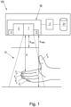
- FIG. 1 shows a fingerprint recognition arrangement 100 according to the invention for carrying out a method according to the invention for capturing fingerprints.
- the fingerprint recognition arrangement 100 comprises a recording arrangement 50 and a processing unit 2 in which data 21 is stored are.
- the recording arrangement 50 comprises an image recording unit 1, a distance sensor 3 and lighting means 4.
- the image recording unit 1 is, for example, a camera whose lens can be focused.
- a liquid lens One form of realization of such a lens is referred to as a liquid lens and is based on the principle of electrowetting, according to which the interface between two liquids changes when a voltage is applied.
- the distance sensor 3 of the recording arrangement 50 can be a time of flight sensor, for example.
- a time-of-flight sensor determines the distance to an object using the transit time method. For this purpose, for example, a light pulse is emitted and the transit time that the light needs to reach the object and back to the sensor is determined. This required travel time is directly proportional to the distance of the object.
- this compact hardware structure is that it can also be built into a mobile device such as a smartphone or tablet, so that no voluminous three-dimensional detection sensors are required.
- a fingerprint recognition arrangement 100 can also be designed to be mobile and portable.
- the image recording unit 1 and the distance sensor 3 are calibrated to each other and the lighting means 4, for example light-emitting diodes, are arranged around the image recording unit 1 in order to ensure sufficient illumination of the detection area 10 of the image recording unit 1.
- the detection range 10 of the image recording unit 1 is limited by the distances d min and d max , the distance d max being chosen such that the required resolution of the fingerprints of z. B. at least 500 DPI is guaranteed and the distance d min is chosen so that four fingers of one hand are still visible in image B at the same time.
- the fingerprint recognition arrangement 100 automatically starts capturing fingerprints as soon as one or more fingers F i ; F 1 , .
- i denotes an index i ⁇ 1,2,...10 ⁇ , which characterizes the respectively recorded or viewed finger (F i ) of the user.
- the thumb F 5 of the user is located outside of the detection area 10 of the image recording unit 1.
- the user's fingers F i , i ⁇ 1,2, . . . 10 ⁇ are uniformly illuminated with different light spectra in the exemplary embodiment shown .
- Illumination means 4 e.g. B. Light-emitting diodes. Due to the high intensity of the light, the nature of the ambient lighting is advantageously irrelevant and the background in a recorded image B is recorded very dark. Furthermore, recording such an image recording B requires only a short exposure time, so that blurriness effects caused by, for example, movement of the fingers F i , i ⁇ 1,2, . . . 10 ⁇ and/or the fingerprint recognition arrangement 100 are reduced or completely avoided.
- a distance measurement is first carried out between the image recording unit 1 and the fingers F i located in the image recording area 10 of the image recording unit 1 and a relevant object distance value d is determined for the relevant finger F i .
- At least one focal plane with a focal plane distance ak is determined, the depth of field of which encloses the determined object distance d as closely as possible or corresponds to it as closely as possible (see Figure 2a ):
- the focal plane distance values a k , k ⁇ 1,...,K ⁇ can lie within a predefined distance value interval around the object distance value d determined in method step b) and in predefined distance value steps from one another be spaced.
- k designates an index k ⁇ 1,...,K ⁇ , which specifies the respective focal plane.
- the respective associated focus plane distance value a k is stored (see Figure 2a ).
- j denotes an index j ⁇ 1,...,M ⁇ , which characterizes the image recording (B j ) considered in each case.
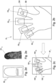
- the focal plane distance value a k is determined in an interval of a predetermined number of z. B. millimeters to the measured object distance value d varies. The width of the distance value interval and the spacing of the distance value steps from one another can be varied as required. In this way, as in Figure 2a shown, a number of M images B j are created and stored with the associated focus plane distance values a k k ⁇ 1,...,K ⁇ .
- the resolution of the recorded image B j is reduced before the scaling, and a reduced image B j j is calculated.
- a segmentation and contour tracing is performed on the reduced image B ⁇ j and the position and/or location of the finger images FB ⁇ i,j of the user's fingers F i in the reduced image B ⁇ j is determined in such a way as is shown in Figure 2c is shown.
- the positions of the associated recorded finger images FB i,j in the created image recording B j which correspond to the finger images FB ⁇ i, j determined in the reduced image B ⁇ j , are then reduced by extrapolating the positions of the finger images FB ⁇ i,j in Image B ⁇ j calculated.
- FIG. 12 shows an example of a captured finger image FB i,j containing background and skin color information.
- the segmentation is based, for example, on the detection of skin color C Stein, C Nickel, and C Busch. Finger photo recognition with smartphone cameras.
- BIOSIG Biometrics Special Interest Group
- pages 1-12, Darmstadt, Germany, Sept 2012 and is simplified by the strong illumination described above.
- various filter masks are combined in the segmentation of a reduced image B ⁇ j and the finger images FB ⁇ i ,j of fingers F i or fingerprints recognizable in the reduced image B ⁇ j are separated from the background information.
- Individual fingers F i or the location and position of their finger images FB ⁇ i,j are recognized, for example, by means of contour tracking and a rectangular-oriented window or limitation BB is defined around the respective finger F i .
- the recorded finger images FB i,j of individual fingers F i can also be determined individually from the individually created image recordings B j .
- the finger images FB i,j can be individually scaled for each finger F i according to the distance value a k , k ⁇ 1, . . . , K ⁇ determined for the finger F i .
- Finger images FB i,j for a number of fingers F i i ⁇ 1,...,10 ⁇ are extracted from each recorded image B j by means of the segmentation described above.
- an example is shown with four fingers F i i ⁇ 1,...,4 ⁇ - four finger images FB 1,j ,..., FB 4,j of fingers F 1 ,..., F 4 , namely des index finger, middle finger, ring finger and little finger, extracted using the segmentation described above.
- the fingerprints FP i,j are extracted from the individual finger images FB i,j of the fingers F i in a further processing step, which is shown, for example, in Liu, Xinwei, et al. "An improved 3-step contactless fingerprint image enhancement approach for minutiae detection.”
- Visual Information Processing EUVIP
- An example of such a fingerprint or fingerprint FP i,j is in Figure 2e shown.
- the contrast of the ridges or papillary ridges is enhanced to improve the quality of the extracted fingerprints, wherein the enhancement of the contrast is enhanced by means of mean-variance, normalization, normalized box filtering and/or morphological operations.
- the distance value ak can be used to select a scaling of the recorded image B j to a predetermined resolution, the scaling in this case being carried out, for example, directly proportional to the distance value ak .
- an image stack is first created from the recorded images B j j ⁇ 1,...,M ⁇ and all finger images FB i,j in the image stack determined and those finger images FB i,j* (j* refers to the optimal image recording B j for the finger F i ) individually determined for each recorded finger F i whose quality is recognized as optimal based on at least one predetermined quality measure.
- the finger images FB i,j of the individual fingers F i are extracted and their quality is evaluated in real time.
- the sharpness of the image is first used as a quality measure for determining the optimal finger images FB i,j* and evaluated individually for each individual finger F i .
- all finger images FB i,j of an image stack are arranged in relative order for each finger F i individually on the basis of their image sharpness.
- the calculation of the image sharpness can be done, for example, as in Eskicioglu, Ahmet M., and Paul S. Fisher. "Image quality measures and their performance.” IEEE Transactions on communications 43.12 (1995): 2959-2965 described, take place and is not regarded as an absolute measure, but is used to create a sequence of the finger images FB i,j .
- the papillary ridge or ridge frequency f is used as a quality measure in addition to the image sharpness, with the papillary ridge frequency f being determined locally in the center of each fingerprint FP i,j .
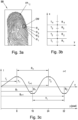
- Figure 3a illustrates the calculation of the ridge frequency f.
- the ridge frequency f is determined locally in at least one rectangular window OW of a fingerprint FP i,j .
- a window OW can also have a square area.
- Figure 3a shows such a window OW in which the fingerprint FP i,j of a detected finger F i with four papillary ridges R 1 , R 2 , R 3 , R 4 can be seen.
- the images of the papillary ridges R 1 , R 2 , R 3 , R 4 are first determined in the window OW using the brightness values recorded with the individual pixels of the image recording unit 1 .
- the center of the window OW is defined as the origin of a two-dimensional coordinate system in the plane of the fingerprint FP i,j or the image area.
- One coordinate axis of the coordinate system is orthogonal to the local direction of the ridges R 1 , R 2 , R 3 , R 4 and the other coordinate axis is parallel to the local direction of the ridges R 1 , R 2 , R 3 , R 4 , as shown in Fig Figure 3b is shown.
- the local ridge frequency f(x,y) is taken at point (x,y) as the inverse of the proportion of ridges per unit length along a segment centered at point (x,y) and orthogonal to the local Direction of the papillary ridges R 1 , R 2 , R 3 , R 4 or ridges set.
- the local ridge direction at position (x,y) is described by the angle ⁇ (x,y).
- the angle ⁇ (x,y) at the position (x,y) in the window OW is defined as the angle between the ridge tangent and the horizontal axis and is determined in the range [0 ... PI[.
- the gradient at point (x,y) is a two-dimensional vector with components ⁇ x and ⁇ y .
- the local ridge frequency f(x,y) at point (x,y) is the inverse of the number of ridges per unit length along a segment centered at (x,y) and orthogonal to the local ridge direction.
- an N ⁇ M pixel window OW is first rotated around ⁇ (x,y) centered at point (x,y), so that the y-axis is parallel to the ridge direction.
- the average length of a ridge valley pair at a resolution of 500 PPI is 8 to 12 pixels, these average lengths are used as thresholds to eliminate fingerprints FP i,j whose average ridge frequency f is significantly different from the average length of a Ridge Valley pair.
- the NFIQ 2.0 value is used as a further quality measure for determining the optimal fingerprints FP i,j for each finger F i .
- NFIQ 2.0 is open source software for evaluating the quality of fingerprint images (see NFIQ 2.0 - NIST fingerprint image quality", National Institute of Standards and Technology, 2016).
- FP i,j is used for all fingerprints NFIQ 2.0 value between 0 and 100 is determined using the distance value a i assigned in the second method step. A fingerprint FP i,j is rejected if the determined NFIQ 2.0 value is below a predetermined threshold value.
- fingerprint FP i,j is recognized as optimal whose papillary ridge frequency f is within the specified frequency interval and which is ranked as relatively sharpest and whose determined NFIQ 2.0 value is above the specified threshold value. This procedure is carried out for each individual finger F i that was recorded by the image recording unit 1, so that an optimal fingerprint FP i ,j* is finally available for each of the recorded fingers F i .
- a one-off calibration can be carried out for each implementation of the recording arrangement 50 .
- the lens elements are configured differently, ie an adjustment of the lens elements z. B. by changing the shape and / or position is made.
- the associated focal plane distance value a k is determined by the image recording unit 1 approaching the calibration pattern and repeated recordings of the calibration pattern are stored with the associated object distances d i . In doing so, the focal plane is traversed.
- a large aperture is selected during calibration and also during later operation in order to ensure a small depth of field, ie a small extension of the sharply imaged area in the object space of the imaging optical system of the image recording unit 1 .
- the depth of field s or the corresponding focal plane with the focal plane distance value a k can be assigned to exactly one distance value d i between the recorded object or finger F and the image recording unit 1 .
- Fingerprints FP i,j in method step d) used the focal plane object distance table. According to the invention, a scaling table is also used, which will be discussed in more detail below.
- G is the object size [mm] and B is the size of the image [mm] given by the imaging unit, d is the object distance [mm] and BW' is the focal length [mm].
- SenRes hor indicates the horizontal pixel resolution of the sensor or the image recording unit 1 .
- DPI is used synonymously with PPI for the resolution or point density.
- a second one-off calibration for the scaling is carried out.
- a calibration pattern with known dimensions is used and the same calibration process as described above is run through.
- the image resolution for example in DPI, is calculated using the known metric values of the calibration pattern. This type of calibration thus enables the conversion of image pixels into metric sizes.
- the determined values are stored in a scaling table.
- the scaling to a specified resolution or point density of greater than or equal to 500 DPI is carried out individually for the fingerprints FB i,j or fingerprints FP i,j in order to achieve a particularly sharp and precise reproduction of the fingerprints or fingerprints FP i,j of the individual fingers F i of the user.
- a registration of those finger images FB i,j or fingerprints FP i,j of a finger F i can optionally be carried out after the scaling in method step c).
- a rectangular boundary BB is defined for each image area, which has, for example, two edges parallel to the longitudinal axis of the finger image FB i,j or fingerprints FP i,j of the finger and two edges parallel to the longitudinal axis of the finger image FB i,j or Fingerprints FP i,j of the finger F i normal edges are determined and a rotation is determined in which the rectangular boundary BB of the image area is smallest, which is finally applied to the respective image area, as shown in Figure 2b is shown schematically.
- the scaling to a specified resolution or point density of greater than or equal to 500 DPI is carried out individually for the fingerprints FB i,j or fingerprints FP i,j in order to achieve a particularly sharp and precise reproduction of the fingerprints or fingerprints FP i,j of the individual fingers F i of the user.
- a registration of those finger images FB i,j or fingerprints FP i,j of a finger F i can optionally be carried out after the scaling in method step c).
- a rectangular boundary BB is defined for each image area, which has, for example, two edges parallel to the longitudinal axis of the finger image FB i,j or fingerprints FP i,j of the finger and two edges parallel to the longitudinal axis of the finger image FB i,j or Fingerprints FP i,j of the finger F i normal edges are determined and a rotation is determined in which the rectangular boundary BB of the image area is smallest, which is finally applied to the respective image area, as shown in Figure 2b is shown schematically.
Landscapes
- Engineering & Computer Science (AREA)
- Theoretical Computer Science (AREA)
- General Physics & Mathematics (AREA)
- Physics & Mathematics (AREA)
- Multimedia (AREA)
- Computer Vision & Pattern Recognition (AREA)
- Human Computer Interaction (AREA)
- Artificial Intelligence (AREA)
- Evolutionary Computation (AREA)
- Databases & Information Systems (AREA)
- Software Systems (AREA)
- Medical Informatics (AREA)
- General Health & Medical Sciences (AREA)
- Computing Systems (AREA)
- Health & Medical Sciences (AREA)
- Data Mining & Analysis (AREA)
- Life Sciences & Earth Sciences (AREA)
- Bioinformatics & Cheminformatics (AREA)
- Bioinformatics & Computational Biology (AREA)
- Evolutionary Biology (AREA)
- General Engineering & Computer Science (AREA)
- Image Input (AREA)
- Collating Specific Patterns (AREA)
Claims (12)
- Procédé de détection d'empreintes digitales avec un dispositif de reconnaissance d'empreinte digitale (100) comprenant une unité d'enregistrement d'image (1), en particulier portable mobile, dans lequel la netteté de l'unité d'enregistrement d'image (1) peut être réglée sur une pluralité de plans de netteté, dans lequela) la distance de l'objet (d) entre l'unité d'enregistrement d'image (1) et un ou plusieurs doigts (Fi) dans la zone de détection (10) de l'unité d'enregistrement d'image (1) est mesurée au moyen d'un capteur de distance (3),b) au moins un plan de netteté avec une valeur de distance de plan de netteté (ak) correspondant à la distance de l'objet (d) calculée est calculé,c) au moins un enregistrement d'image (Bj) d'un ou plusieurs doigts (Fi), qui se trouvent dans la zone de détection (10) de l'unité d'enregistrement d'image (1), est établi avec l'unité d'enregistrement d'image (1) dans le plan de netteté calculé précédemment,d) en raison de la valeur de distance de plan de netteté (ak) du plan de netteté calculé, une mise à l'échelle au moins d'une partie de l'enregistrement d'image (Bj) est entreprise, dans lequel la mise à l'échelle est réalisée à une résolution prédéfinie, en particulier à une densité de points prédéterminée, de préférence indiquée en DPI, caractérisé en ce que- la mise à l'échelle est directement proportionnelle à la valeur de distance de plan de netteté (ak) calculée,- un dispositif de reconnaissance d'empreinte digitale (100), dont la spécification technique, en particulier le paramètre de caméra de l'unité d'enregistrement d'image (1) n'est pas connu au préalable, est utilisé et un tableau de mise à l'échelle est utilisé pour la mise à l'échelle des images de doigt (FBi,j) et/ou des empreintes digitales (FPi,j) dans l'étape d),- pour l'établissement du tableau de mise à l'échelle, un calibrage du dispositif de reconnaissance d'empreinte digitale (100) est réalisé avec un modèle de calibrage avec des dimensions connues, et- en ce que pour une pluralité de configurations de lentille de l'unité d'enregistrement d'image (1) et des plans de netteté afférents respectivement avec leurs valeurs de distance de plan de netteté (ak) respectives respectivement- le modèle de calibrage avec des dimensions connues est déplacé à une distance différente de l'unité d'enregistrement d'image (1) à travers la zone de détection (10) de l'unité d'enregistrement d'image (1),- dans lequel respectivement des enregistrements d'image du modèle de calibrage sont établis et la distance de l'objet (di) afférente est calculée,- dans lequel l'enregistrement d'image est calculé, dont la qualité est reconnue à l'aide d'au moins une mesure de qualité prédéfinie comme optimale, dans lequel en particulier l'enregistrement d'image classée relativement la plus nette est reconnu comme optimal,- dans lequel pour l'enregistrement d'image reconnu comme optimal, un calcul de la résolution d'image, en particulier en DPI, est entrepris sur la base des dimensions connues du modèle de calibrage, et- dans lequel la résolution d'image calculée de cette manière, en particulier en DPI, est enregistrée conjointement avec la distance de l'objet (di*) afférente à l'enregistrement d'image reconnue comme optimal comme valeur de distance de plan de netteté (ak) du plan de netteté respectif dans le tableau de mise à l'échelle.
- Procédé selon la revendication 1, dans lequel avant l'étape d)- au moins une image (B^j) réduite est calculée par la réduction de la résolution d'au moins un enregistrement d'image (Bj) établi à l'étape c),- la position et/ou la couche d'une ou plusieurs images de doigt (FB^i,j) d'un ou plusieurs doigts (Fi) sont calculées dans l'image réduite (B^j) par la segmentation et l'application d'un algorithme de suivi de contour,- dans l'enregistrement d'image (Bj) établi, les positions de l'image de doigt enregistrée ou de plusieurs images de doigt (FBi,j) enregistrées qui correspondent respectivement aux images de doigt (FB^i,j) calculées dans l'image réduite (B^j), sont calculées par extrapolation et- dans l'étape d), les parties ainsi calculées de l'enregistrement d'image (Bj), dans lesquelles l'image de doigt (FBi,j) enregistrée d'un doigt (Fi) a été calculée, sont mises à l'échelle,
dans lequel il est en particulier prévu que les parties de l'enregistrement d'image (Bj), dans lesquelles aucune image de doigt (FBi,j) d'un doigt (Fi) n'a été calculée, sont rejetées. - Procédé selon la revendication 1 ou 2, dans lequel après l'étape d), une conversion des images de doigt (FBi,j) enregistrées est entreprise dans un format d'empreinte digitale, dans lequel les empreintes digitales (FPi,j) ainsi converties reproduisent les images des crêtes papillaires (R1, ..., R4) des doigts (Fi), en particulier sous la forme d'une image de couleur grise numérique.
- Procédé selon l'une quelconque des revendications précédentes, dans lequel entre l'étape c) et l'étape d)- une suite d'enregistrements d'image (Bj) est établie, dans lequel les enregistrements d'image (Bj) sont enregistrés par l'unité d'enregistrement d'image (1) avec différentes valeurs de distance de plan de netteté (ak),- dans lequel les valeurs de distance de plan de netteté (ak) se trouvent dans un intervalle de valeur de distance prédéfini autour de la distance de l'objet (d) calculée dans l'étape a) et sont espacées les unes par rapport aux autres dans des incréments de valeur de distance prédéfinis , et- dans lequel avec chaque enregistrement d'image (Bj), la valeur de distance de plan de netteté (ak) respectivement afférente est enregistrée,- une pile d'image est établie à partir des enregistrements d'image (Bj) établis de la sorte,- les images de doigt (FBi,j) et/ ou empreintes digitales (FPi,j) sont calculées à partir des enregistrements d'image (Bi,j) établis et- l'image de doigt (FBi,j) et/ou l'empreinte digitale (FPi,j) est calculée en particulier individuellement pour chaque doigt (Fi) enregistré, dont la qualité est reconnue à l'aide d'au moins une mesure de qualité prédéfinie comme optimale,- dans lequel il est en particulier prévu que pour la fixation de la mise à l'échelle dans l'étape d), la valeur de distance de plan de netteté (ak) de l'image de doigt (FBi,j*) et/ou empreinte digitale (FPi,j*) reconnue comme optimale est utilisée.
- Procédé selon la revendication 4, dans lequel comme mesure de qualité pour le calcul des images de doigt (FBi,j*) et/ou empreintes digitales (FPi,j*) optimales dans la pile d'image- la netteté d'image est utilisée, dans lequel un classement relatif d'images de doigt (FBi,j) et/ou empreintes d'image (FPi,j) sélectionnées, en particulier toutes, d'une pile d'image est entrepris à l'aide de leur netteté d'image et/ou- la fréquence de crêtes papillaires (f) est utilisée,- dans lequel la fréquence de crêtes papillaires (f) pour chaque image de doigt (FBi,j) et/ou chaque empreinte digitale (FPi,j) est calculée et- dans lequel il est vérifié si la fréquence de crête papillaire (f) calculée pour l'image de doigt (FBi,j) respective et/ou l'empreinte digitale (FPi,j) respective se trouve dans l'intervalle de fréquence prédéfinie et- dans lequel l'image de doigt (FBi,j) respective et l'empreinte digitale (FPi,j) respective est rejetée lorsque la fréquence de crête papillaire calculée (f) se trouve en dehors de l'intervalle de fréquence et/ou- la valeur NFIQ 2.0 est utilisée,- dans lequel pour des images de doigt (FBi,j) et/ou empreintes digitales (FPi,j) sélectionnées, une valeur NFIQ. 2.0 est calculée entre 0 et 100 en utilisant la valeur de distance de plan de netteté (ak) calculée dans l'étape c) et des images de doigt (FBi,j) et/ou empreintes digitales (FPi,j) mises à l'échelle dans l'étape d) et- dans lequel l'image de doigt (FBi,j) et/ou l'empreinte digitale (FPi,j) est rejetée lorsque la valeur NFIQ 2.0 calculée se trouve en dessous d'une valeur seuil prédéfinie.
- Procédé selon la revendication 5, dans lequel la fréquence de crête papillaire (f) est calculée dans au moins une fenêtre (OW) rectangulaire ou carrée dans une image de doigt (FBi,j) et/ou empreinte digitale (FPi,j) d'un doigt (Fi),- dans lequel dans l'image de doigt (FBi,j) et/ou empreinte digitale (FPi,j) les images de crêtes papillaires (R1, ..., R4) sont calculées à l'aide des valeurs de luminosité détectées avec les pixels individuels de l'unité d'enregistrement d'image (1),- dans lequel le centre de la fenêtre (OW) est fixé comme origine d'un système de coordonnées en deux dimensions dans le plan de l'image de doigt (FBi,j) et/ou empreinte digitale (FPi,j), un axe de coordonnées du système de coordonnées est fixé orthogonalement au sens local des crêtes papillaires (R1, ..., R4) et l'autre axe de coordonnées est fixé parallèlement au sens local des crêtes papillaires (R1,..., R4),- le nombre de crêtes papillaires (R1, ..., R4) est calculé dans une longueur d'unité prédéfinie orthogonalement au sens local des crêtes papillaires (R1, ..., R4) dans la fenêtre (OW) à l'aide des valeurs de luminosité, et- la fréquence de crête papillaire (f) est calculée comme l'inverse du nombre de crêtes papillaires (R1, ..., R4) par longueur d'unité prédéfinie orthogonalement au sens local des crêtes papillaires (R1, ..., R4).
- Procédé selon la revendication 5 ou 6, dans lequel pour chaque doigt, l'image de doigt (FBi,j) et/ou l'empreinte digitale (FPi,j) d'une pile d'image est reconnue comme optimale,- dont la fréquence de crêtes papillaires (f) se situe au sein de l'intervalle de fréquence prédéterminé, et/ou- dont le classement est relativement le plus net, et/ou- dont la valeur NFIQ. 2.0 déterminée est supérieure à la valeur seuil prédéterminée.
- Procédé selon la revendication 7, dans lequel à l'étape d), la mise à l'échelle à une résolution prédéfinie, en particulier supérieure ou égale à 500 DPI, est réalisée individuellement pour chaque image de doigt (FBi,j) et/ou chaque empreinte digitale (FPi,j).
- Procédé selon l'une quelconque des revendications précédentes, dans lequel pour la sélection de la valeur de distance de plan de netteté (ak) à l'aide de la distance de l'objet (di) mesurée, un tableau de distance de l'objet de plan de netteté est utilisé,- dans lequel pour déterminer le tableau de distance de l'objet de plan de netteté, un calibrage du dispositif de reconnaissance d'empreintes digitales (100) est réalisé avec un modèle de calibrage,- dans lequel pour une pluralité de configurations de lentille connues de l'unité d'enregistrement d'image (1) et des plans de netteté afférents respectivement avec leurs valeurs de distance de plan de netteté (ak) respectives respectivement- le modèle de calibrage est déplacé à une distance différente de l'unité d'enregistrement d'image (1) à travers la zone de détection (10) de l'unité d'enregistrement d'image (1),
dans lequel respectivement des enregistrements d'image du modèle de calibrage sont réalisés et la distance d'objet (di) correspondante est déterminée,- dans lequel l'enregistrement d'image, dont la qualité est reconnue comme optimale à l'aide d'au moins une mesure de qualité prédéterminée, est déterminé, dans lequel en particulier l'enregistrement d'image classé relativement le plus net est reconnu comme optimal, et- dans lequel la distance de l'objet (di*) afférente à l'enregistrement d'image reconnue comme optimale est enregistrée comme la valeur de distance de plan de netteté (ak) du plan de netteté respectif conjointement avec la configuration de lentille afférente dans le tableau de distance d'objet de plan de netteté. - Procédé selon l'une quelconque des revendications précédentes, dans lequel à la suite de la mise à l'échelle de l'étape d), un enregistrement des images de doigt (FBi,j) et/ou des empreintes digitales (FPi,j) est réalisé, dans lequel- une limitation rectangulaire (BB), en particulier une Bounding Box, de préférence avec deux bords parallèles à l'axe longitudinal de l'image de doigt (FBi,j) ou de l'empreinte digitale (FPi,j) du doigt (Fi) et deux bords perpendiculaires à l'axe longitudinal de l'image de doigt (FBi,j) ou de l'empreinte digitale (FPi,j) du doigt (Fi), est définie pour chaque image de doigt (FBi,j) et/ou chaque empreinte digitale (FPi,j), et- une rotation, pour laquelle la limitation rectangulaire de la zone d'image est la plus petite, est déterminée et appliquée à la limitation (BB) respective, en particulier à la Bounding Box.
- Support de données lisible par ordinateur comprenant des ordres qui, lorsqu'ils sont réalisés par un ordinateur qui est relié à un capteur de distance (3) et une unité d'enregistrement d'image (1), incitent l'ordinateur à réaliser le procédé selon l'une quelconque des revendications 1 à 10.
- Dispositif de reconnaissance d'empreinte digitale (100) pour la détection d'empreintes digitales, en particulier réalisé comme terminal portable mobile, comprenant une unité d'enregistrement d'image (1), dans lequel la netteté de l'unité d'enregistrement d'image (1) peut être réglée sur une pluralité de plans de netteté,- un capteur de distance (3), dans lequel le capteur de distance est prévu pour la détermination de la distance de l'objet (d) entre l'unité d'enregistrement d'image (1) et un ou plusieurs doigts (Fi) dans la zone de détection (10) de l'unité d'enregistrement d'image (1),- une unité de traitement (2) réalisée pour la réalisation d'un procédé selon l'une quelconque des revendications 1 à 10 et/ou contenant un support de données selon la revendication 11.
Applications Claiming Priority (1)
| Application Number | Priority Date | Filing Date | Title |
|---|---|---|---|
| ATA51083/2018A AT521935A1 (de) | 2018-12-05 | 2018-12-05 | Verfahren zur Erfassung von Fingerabdrücken |
Publications (3)
| Publication Number | Publication Date |
|---|---|
| EP3663981A1 EP3663981A1 (fr) | 2020-06-10 |
| EP3663981B1 true EP3663981B1 (fr) | 2023-09-06 |
| EP3663981C0 EP3663981C0 (fr) | 2023-09-06 |
Family
ID=68807998
Family Applications (1)
| Application Number | Title | Priority Date | Filing Date |
|---|---|---|---|
| EP19213847.7A Active EP3663981B1 (fr) | 2018-12-05 | 2019-12-05 | Procédé de détection d'empreintes digitales |
Country Status (2)
| Country | Link |
|---|---|
| EP (1) | EP3663981B1 (fr) |
| AT (1) | AT521935A1 (fr) |
Cited By (1)
| Publication number | Priority date | Publication date | Assignee | Title |
|---|---|---|---|---|
| AT528003B1 (de) * | 2024-06-13 | 2025-09-15 | Ait Austrian Inst Tech Gmbh | Verfahren zur Erfassung von Fingerabdrücken |
Families Citing this family (2)
| Publication number | Priority date | Publication date | Assignee | Title |
|---|---|---|---|---|
| EP4468261A1 (fr) | 2023-05-24 | 2024-11-27 | AIT Austrian Institute of Technology GmbH | Procédé de correction de pose de doigt dans des images d'empreintes digitales en 2d |
| EP4553780A3 (fr) * | 2023-10-19 | 2025-07-16 | Touchless Biometric Systems AG | Appareil de vérification et/ou d'identification biométriques |
Family Cites Families (5)
| Publication number | Priority date | Publication date | Assignee | Title |
|---|---|---|---|---|
| US8600123B2 (en) * | 2010-09-24 | 2013-12-03 | General Electric Company | System and method for contactless multi-fingerprint collection |
| US8971588B2 (en) * | 2011-03-30 | 2015-03-03 | General Electric Company | Apparatus and method for contactless high resolution handprint capture |
| US9734381B2 (en) * | 2014-12-17 | 2017-08-15 | Northrop Grumman Systems Corporation | System and method for extracting two-dimensional fingerprints from high resolution three-dimensional surface data obtained from contactless, stand-off sensors |
| CN109716348B (zh) * | 2016-08-12 | 2024-05-28 | 3M创新有限公司 | 独立地处理多个所关注的区域 |
| KR20260030840A (ko) * | 2016-12-08 | 2026-03-06 | 베라디움 아이피 리미티드 | 모바일 디바이스를 사용하여 캡처된 화상을 사용하여 지문 기반 사용자 인증을 수행하기 위한 시스템 및 방법 |
-
2018
- 2018-12-05 AT ATA51083/2018A patent/AT521935A1/de not_active Application Discontinuation
-
2019
- 2019-12-05 EP EP19213847.7A patent/EP3663981B1/fr active Active
Cited By (3)
| Publication number | Priority date | Publication date | Assignee | Title |
|---|---|---|---|---|
| AT528003B1 (de) * | 2024-06-13 | 2025-09-15 | Ait Austrian Inst Tech Gmbh | Verfahren zur Erfassung von Fingerabdrücken |
| AT528003A4 (de) * | 2024-06-13 | 2025-09-15 | Ait Austrian Inst Tech Gmbh | Verfahren zur Erfassung von Fingerabdrücken |
| WO2025255604A1 (fr) * | 2024-06-13 | 2025-12-18 | Ait Austrian Institute Of Technology Gmbh | Procédé de détection sans contact d'empreintes digitales |
Also Published As
| Publication number | Publication date |
|---|---|
| AT521935A1 (de) | 2020-06-15 |
| EP3663981A1 (fr) | 2020-06-10 |
| EP3663981C0 (fr) | 2023-09-06 |
Similar Documents
| Publication | Publication Date | Title |
|---|---|---|
| DE60307583T2 (de) | Auswertung der Schärfe eines Bildes der Iris eines Auges | |
| DE60213600T2 (de) | Verfahren und gerät zur extraktion eines bedeutsamen gebiets in einem durch überstreichende aufnahme gewonnenen bild einer biologischen oberfläche | |
| DE19614975C2 (de) | Gesichtsbildverarbeitungssystem | |
| DE60130073T2 (de) | Gerät zur Erfassung von Fingerabdruckbildern | |
| EP2584493B1 (fr) | Procédé de distinction entre un visage réel et une représentation bidimensionnelle du visage dans un processus d'enregistrement biométrique | |
| DE4421242B4 (de) | Bilderfassungseinrichtung für ein Identifikationssystem | |
| DE60210348T2 (de) | Bildidentifizierungssystem | |
| DE60213490T2 (de) | Gerät und Verfahren zur Fingerabdruckerkennung | |
| EP1693781B1 (fr) | Procédé et disposition pour l'enregistrement optique de données digitales biométriques | |
| EP3663981B1 (fr) | Procédé de détection d'empreintes digitales | |
| DE102014117102B4 (de) | Spurwechselwarnsystem und Verfahren zum Steuern des Spurwechselwarnsystems | |
| EP3959497B1 (fr) | Procédé et dispositif de mesure de la force de rupture locale ou de la distribution de la force de rupture d'un verre de lunettes | |
| DE102013112040B4 (de) | System und Verfahren zum Auffinden von sattelpunktartigen Strukturen in einem Bild und Bestimmen von Informationen daraus | |
| DE112019004745B4 (de) | Vorrichtung und verfahren zum bestimmen einer profiltiefe | |
| DE102010001331A1 (de) | Iris-Deblurring-Verfahren basierend auf globalen und lokalen Irisbildstatistiken | |
| EP3663976B1 (fr) | Procédé de détection d'empreintes digitales | |
| DE102017220752A1 (de) | Bildverarbeitungsvorrichtung, Bildbverarbeitungsverfahren und Bildverarbeitungsprogramm | |
| EP3730918A1 (fr) | Procédé et dispositif de mesure de la force de rupture locale et / ou de la répartition de la force de rupture d'un verre de lunettes | |
| DE112019004112T5 (de) | System und verfahren zur analyse mikroskopischer bilddaten und zur erzeugung eines annotierten datensatzes zum training der klassifikatoren | |
| DE602004009875T2 (de) | Verfahren zur Bildverarbeitung für Profilbestimmung mittels strukturiertem Lichts | |
| EP3931798B1 (fr) | Estimation du déplacement d'une position d'image | |
| DE102018121317B4 (de) | Verfahren, Vorrichtung und Computerprogramm zur Schätzung einer durch eine Freiraumgeste vermittelten Richtungsinformation zur Bestimmung einer Benutzereingabe an einer Mensch-Maschine-Schnittstelle | |
| WO2018234251A1 (fr) | Procédé et dispositif de détection d'une entrée utilisateur en fonction d'un geste | |
| AT528003B1 (de) | Verfahren zur Erfassung von Fingerabdrücken | |
| EP3142068B1 (fr) | Procede de detection tridimensionnelle d'objets |
Legal Events
| Date | Code | Title | Description |
|---|---|---|---|
| PUAI | Public reference made under article 153(3) epc to a published international application that has entered the european phase |
Free format text: ORIGINAL CODE: 0009012 |
|
| STAA | Information on the status of an ep patent application or granted ep patent |
Free format text: STATUS: THE APPLICATION HAS BEEN PUBLISHED |
|
| AK | Designated contracting states |
Kind code of ref document: A1 Designated state(s): AL AT BE BG CH CY CZ DE DK EE ES FI FR GB GR HR HU IE IS IT LI LT LU LV MC MK MT NL NO PL PT RO RS SE SI SK SM TR |
|
| AX | Request for extension of the european patent |
Extension state: BA ME |
|
| STAA | Information on the status of an ep patent application or granted ep patent |
Free format text: STATUS: REQUEST FOR EXAMINATION WAS MADE |
|
| 17P | Request for examination filed |
Effective date: 20201210 |
|
| RBV | Designated contracting states (corrected) |
Designated state(s): AL AT BE BG CH CY CZ DE DK EE ES FI FR GB GR HR HU IE IS IT LI LT LU LV MC MK MT NL NO PL PT RO RS SE SI SK SM TR |
|
| STAA | Information on the status of an ep patent application or granted ep patent |
Free format text: STATUS: EXAMINATION IS IN PROGRESS |
|
| R17P | Request for examination filed (corrected) |
Effective date: 20201210 |
|
| RIN1 | Information on inventor provided before grant (corrected) |
Inventor name: WEISSENFELD, AXEL Inventor name: ZOUFAL, ANDREAS Inventor name: FERNANDEZ, GUSTAVO Inventor name: CYNIBURK, MICHAEL Inventor name: WEISS, CHRISTOPH Inventor name: VOKO, ERICH Inventor name: STROBL, BERNHARD |
|
| 17Q | First examination report despatched |
Effective date: 20221107 |
|
| REG | Reference to a national code |
Ref country code: DE Ref legal event code: R079 Free format text: PREVIOUS MAIN CLASS: G06K0009340000 Ipc: G06V0040130000 Ref country code: DE Ref legal event code: R079 Ref document number: 502019009240 Country of ref document: DE Free format text: PREVIOUS MAIN CLASS: G06K0009340000 Ipc: G06V0040130000 |
|
| GRAP | Despatch of communication of intention to grant a patent |
Free format text: ORIGINAL CODE: EPIDOSNIGR1 |
|
| STAA | Information on the status of an ep patent application or granted ep patent |
Free format text: STATUS: GRANT OF PATENT IS INTENDED |
|
| RIC1 | Information provided on ipc code assigned before grant |
Ipc: G06F 18/25 20230101ALI20230308BHEP Ipc: G06V 10/80 20220101ALI20230308BHEP Ipc: G06V 40/13 20220101AFI20230308BHEP |
|
| INTG | Intention to grant announced |
Effective date: 20230330 |
|
| GRAS | Grant fee paid |
Free format text: ORIGINAL CODE: EPIDOSNIGR3 |
|
| GRAA | (expected) grant |
Free format text: ORIGINAL CODE: 0009210 |
|
| STAA | Information on the status of an ep patent application or granted ep patent |
Free format text: STATUS: THE PATENT HAS BEEN GRANTED |
|
| AK | Designated contracting states |
Kind code of ref document: B1 Designated state(s): AL AT BE BG CH CY CZ DE DK EE ES FI FR GB GR HR HU IE IS IT LI LT LU LV MC MK MT NL NO PL PT RO RS SE SI SK SM TR |
|
| REG | Reference to a national code |
Ref country code: GB Ref legal event code: FG4D Free format text: NOT ENGLISH |
|
| REG | Reference to a national code |
Ref country code: CH Ref legal event code: EP |
|
| REG | Reference to a national code |
Ref country code: IE Ref legal event code: FG4D Free format text: LANGUAGE OF EP DOCUMENT: GERMAN |
|
| REG | Reference to a national code |
Ref country code: DE Ref legal event code: R096 Ref document number: 502019009240 Country of ref document: DE |
|
| U01 | Request for unitary effect filed |
Effective date: 20230913 |
|
| U07 | Unitary effect registered |
Designated state(s): AT BE BG DE DK EE FI FR IT LT LU LV MT NL PT SE SI Effective date: 20230919 |
|
| PG25 | Lapsed in a contracting state [announced via postgrant information from national office to epo] |
Ref country code: GR Free format text: LAPSE BECAUSE OF FAILURE TO SUBMIT A TRANSLATION OF THE DESCRIPTION OR TO PAY THE FEE WITHIN THE PRESCRIBED TIME-LIMIT Effective date: 20231207 |
|
| U20 | Renewal fee for the european patent with unitary effect paid |
Year of fee payment: 5 Effective date: 20231220 |
|
| PG25 | Lapsed in a contracting state [announced via postgrant information from national office to epo] |
Ref country code: RS Free format text: LAPSE BECAUSE OF FAILURE TO SUBMIT A TRANSLATION OF THE DESCRIPTION OR TO PAY THE FEE WITHIN THE PRESCRIBED TIME-LIMIT Effective date: 20230906 Ref country code: NO Free format text: LAPSE BECAUSE OF FAILURE TO SUBMIT A TRANSLATION OF THE DESCRIPTION OR TO PAY THE FEE WITHIN THE PRESCRIBED TIME-LIMIT Effective date: 20231206 Ref country code: HR Free format text: LAPSE BECAUSE OF FAILURE TO SUBMIT A TRANSLATION OF THE DESCRIPTION OR TO PAY THE FEE WITHIN THE PRESCRIBED TIME-LIMIT Effective date: 20230906 Ref country code: GR Free format text: LAPSE BECAUSE OF FAILURE TO SUBMIT A TRANSLATION OF THE DESCRIPTION OR TO PAY THE FEE WITHIN THE PRESCRIBED TIME-LIMIT Effective date: 20231207 |
|
| PG25 | Lapsed in a contracting state [announced via postgrant information from national office to epo] |
Ref country code: IS Free format text: LAPSE BECAUSE OF FAILURE TO SUBMIT A TRANSLATION OF THE DESCRIPTION OR TO PAY THE FEE WITHIN THE PRESCRIBED TIME-LIMIT Effective date: 20240106 |
|
| PG25 | Lapsed in a contracting state [announced via postgrant information from national office to epo] |
Ref country code: ES Free format text: LAPSE BECAUSE OF FAILURE TO SUBMIT A TRANSLATION OF THE DESCRIPTION OR TO PAY THE FEE WITHIN THE PRESCRIBED TIME-LIMIT Effective date: 20230906 |
|
| PG25 | Lapsed in a contracting state [announced via postgrant information from national office to epo] |
Ref country code: SM Free format text: LAPSE BECAUSE OF FAILURE TO SUBMIT A TRANSLATION OF THE DESCRIPTION OR TO PAY THE FEE WITHIN THE PRESCRIBED TIME-LIMIT Effective date: 20230906 Ref country code: RO Free format text: LAPSE BECAUSE OF FAILURE TO SUBMIT A TRANSLATION OF THE DESCRIPTION OR TO PAY THE FEE WITHIN THE PRESCRIBED TIME-LIMIT Effective date: 20230906 Ref country code: IS Free format text: LAPSE BECAUSE OF FAILURE TO SUBMIT A TRANSLATION OF THE DESCRIPTION OR TO PAY THE FEE WITHIN THE PRESCRIBED TIME-LIMIT Effective date: 20240106 Ref country code: ES Free format text: LAPSE BECAUSE OF FAILURE TO SUBMIT A TRANSLATION OF THE DESCRIPTION OR TO PAY THE FEE WITHIN THE PRESCRIBED TIME-LIMIT Effective date: 20230906 Ref country code: CZ Free format text: LAPSE BECAUSE OF FAILURE TO SUBMIT A TRANSLATION OF THE DESCRIPTION OR TO PAY THE FEE WITHIN THE PRESCRIBED TIME-LIMIT Effective date: 20230906 Ref country code: SK Free format text: LAPSE BECAUSE OF FAILURE TO SUBMIT A TRANSLATION OF THE DESCRIPTION OR TO PAY THE FEE WITHIN THE PRESCRIBED TIME-LIMIT Effective date: 20230906 |
|
| PG25 | Lapsed in a contracting state [announced via postgrant information from national office to epo] |
Ref country code: PL Free format text: LAPSE BECAUSE OF FAILURE TO SUBMIT A TRANSLATION OF THE DESCRIPTION OR TO PAY THE FEE WITHIN THE PRESCRIBED TIME-LIMIT Effective date: 20230906 |
|
| REG | Reference to a national code |
Ref country code: DE Ref legal event code: R097 Ref document number: 502019009240 Country of ref document: DE |
|
| PLBE | No opposition filed within time limit |
Free format text: ORIGINAL CODE: 0009261 |
|
| STAA | Information on the status of an ep patent application or granted ep patent |
Free format text: STATUS: NO OPPOSITION FILED WITHIN TIME LIMIT |
|
| REG | Reference to a national code |
Ref country code: CH Ref legal event code: PL |
|
| 26N | No opposition filed |
Effective date: 20240607 |
|
| PG25 | Lapsed in a contracting state [announced via postgrant information from national office to epo] |
Ref country code: MC Free format text: LAPSE BECAUSE OF FAILURE TO SUBMIT A TRANSLATION OF THE DESCRIPTION OR TO PAY THE FEE WITHIN THE PRESCRIBED TIME-LIMIT Effective date: 20230906 |
|
| GBPC | Gb: european patent ceased through non-payment of renewal fee |
Effective date: 20231206 |
|
| PG25 | Lapsed in a contracting state [announced via postgrant information from national office to epo] |
Ref country code: MC Free format text: LAPSE BECAUSE OF FAILURE TO SUBMIT A TRANSLATION OF THE DESCRIPTION OR TO PAY THE FEE WITHIN THE PRESCRIBED TIME-LIMIT Effective date: 20230906 |
|
| REG | Reference to a national code |
Ref country code: IE Ref legal event code: MM4A |
|
| PG25 | Lapsed in a contracting state [announced via postgrant information from national office to epo] |
Ref country code: IE Free format text: LAPSE BECAUSE OF NON-PAYMENT OF DUE FEES Effective date: 20231205 |
|
| PG25 | Lapsed in a contracting state [announced via postgrant information from national office to epo] |
Ref country code: GB Free format text: LAPSE BECAUSE OF NON-PAYMENT OF DUE FEES Effective date: 20231206 |
|
| PG25 | Lapsed in a contracting state [announced via postgrant information from national office to epo] |
Ref country code: CH Free format text: LAPSE BECAUSE OF NON-PAYMENT OF DUE FEES Effective date: 20231231 |
|
| PG25 | Lapsed in a contracting state [announced via postgrant information from national office to epo] |
Ref country code: IE Free format text: LAPSE BECAUSE OF NON-PAYMENT OF DUE FEES Effective date: 20231205 Ref country code: GB Free format text: LAPSE BECAUSE OF NON-PAYMENT OF DUE FEES Effective date: 20231206 Ref country code: CH Free format text: LAPSE BECAUSE OF NON-PAYMENT OF DUE FEES Effective date: 20231231 |
|
| U20 | Renewal fee for the european patent with unitary effect paid |
Year of fee payment: 6 Effective date: 20241211 |
|
| PG25 | Lapsed in a contracting state [announced via postgrant information from national office to epo] |
Ref country code: CY Free format text: LAPSE BECAUSE OF FAILURE TO SUBMIT A TRANSLATION OF THE DESCRIPTION OR TO PAY THE FEE WITHIN THE PRESCRIBED TIME-LIMIT; INVALID AB INITIO Effective date: 20191205 |
|
| PG25 | Lapsed in a contracting state [announced via postgrant information from national office to epo] |
Ref country code: HU Free format text: LAPSE BECAUSE OF FAILURE TO SUBMIT A TRANSLATION OF THE DESCRIPTION OR TO PAY THE FEE WITHIN THE PRESCRIBED TIME-LIMIT; INVALID AB INITIO Effective date: 20191205 |
|
| PG25 | Lapsed in a contracting state [announced via postgrant information from national office to epo] |
Ref country code: TR Free format text: LAPSE BECAUSE OF FAILURE TO SUBMIT A TRANSLATION OF THE DESCRIPTION OR TO PAY THE FEE WITHIN THE PRESCRIBED TIME-LIMIT Effective date: 20230906 |
|
| U20 | Renewal fee for the european patent with unitary effect paid |
Year of fee payment: 7 Effective date: 20251204 |