EP3664187A1 - Ensemble de cellules de batterie cylindriques à utilisation d'espace et sécurité améliorées et module de batterie le comprenant - Google Patents
Ensemble de cellules de batterie cylindriques à utilisation d'espace et sécurité améliorées et module de batterie le comprenant Download PDFInfo
- Publication number
- EP3664187A1 EP3664187A1 EP18894711.3A EP18894711A EP3664187A1 EP 3664187 A1 EP3664187 A1 EP 3664187A1 EP 18894711 A EP18894711 A EP 18894711A EP 3664187 A1 EP3664187 A1 EP 3664187A1
- Authority
- EP
- European Patent Office
- Prior art keywords
- cylindrical battery
- cell
- cylindrical
- battery cell
- electrode
- Prior art date
- Legal status (The legal status is an assumption and is not a legal conclusion. Google has not performed a legal analysis and makes no representation as to the accuracy of the status listed.)
- Granted
Links
Images


Classifications
-
- H—ELECTRICITY
- H01—ELECTRIC ELEMENTS
- H01M—PROCESSES OR MEANS, e.g. BATTERIES, FOR THE DIRECT CONVERSION OF CHEMICAL ENERGY INTO ELECTRICAL ENERGY
- H01M10/00—Secondary cells; Manufacture thereof
- H01M10/60—Heating or cooling; Temperature control
- H01M10/61—Types of temperature control
- H01M10/613—Cooling or keeping cold
-
- H—ELECTRICITY
- H01—ELECTRIC ELEMENTS
- H01M—PROCESSES OR MEANS, e.g. BATTERIES, FOR THE DIRECT CONVERSION OF CHEMICAL ENERGY INTO ELECTRICAL ENERGY
- H01M10/00—Secondary cells; Manufacture thereof
- H01M10/60—Heating or cooling; Temperature control
- H01M10/62—Heating or cooling; Temperature control specially adapted for specific applications
- H01M10/623—Portable devices, e.g. mobile telephones, cameras or pacemakers
-
- H—ELECTRICITY
- H01—ELECTRIC ELEMENTS
- H01M—PROCESSES OR MEANS, e.g. BATTERIES, FOR THE DIRECT CONVERSION OF CHEMICAL ENERGY INTO ELECTRICAL ENERGY
- H01M10/00—Secondary cells; Manufacture thereof
- H01M10/60—Heating or cooling; Temperature control
- H01M10/64—Heating or cooling; Temperature control characterised by the shape of the cells
- H01M10/643—Cylindrical cells
-
- H—ELECTRICITY
- H01—ELECTRIC ELEMENTS
- H01M—PROCESSES OR MEANS, e.g. BATTERIES, FOR THE DIRECT CONVERSION OF CHEMICAL ENERGY INTO ELECTRICAL ENERGY
- H01M10/00—Secondary cells; Manufacture thereof
- H01M10/60—Heating or cooling; Temperature control
- H01M10/65—Means for temperature control structurally associated with the cells
- H01M10/655—Solid structures for heat exchange or heat conduction
-
- H—ELECTRICITY
- H01—ELECTRIC ELEMENTS
- H01M—PROCESSES OR MEANS, e.g. BATTERIES, FOR THE DIRECT CONVERSION OF CHEMICAL ENERGY INTO ELECTRICAL ENERGY
- H01M10/00—Secondary cells; Manufacture thereof
- H01M10/60—Heating or cooling; Temperature control
- H01M10/65—Means for temperature control structurally associated with the cells
- H01M10/655—Solid structures for heat exchange or heat conduction
- H01M10/6551—Surfaces specially adapted for heat dissipation or radiation, e.g. fins or coatings
-
- H—ELECTRICITY
- H01—ELECTRIC ELEMENTS
- H01M—PROCESSES OR MEANS, e.g. BATTERIES, FOR THE DIRECT CONVERSION OF CHEMICAL ENERGY INTO ELECTRICAL ENERGY
- H01M10/00—Secondary cells; Manufacture thereof
- H01M10/60—Heating or cooling; Temperature control
- H01M10/65—Means for temperature control structurally associated with the cells
- H01M10/655—Solid structures for heat exchange or heat conduction
- H01M10/6554—Rods or plates
-
- H—ELECTRICITY
- H01—ELECTRIC ELEMENTS
- H01M—PROCESSES OR MEANS, e.g. BATTERIES, FOR THE DIRECT CONVERSION OF CHEMICAL ENERGY INTO ELECTRICAL ENERGY
- H01M10/00—Secondary cells; Manufacture thereof
- H01M10/60—Heating or cooling; Temperature control
- H01M10/65—Means for temperature control structurally associated with the cells
- H01M10/655—Solid structures for heat exchange or heat conduction
- H01M10/6556—Solid parts with flow channel passages or pipes for heat exchange
-
- H—ELECTRICITY
- H01—ELECTRIC ELEMENTS
- H01M—PROCESSES OR MEANS, e.g. BATTERIES, FOR THE DIRECT CONVERSION OF CHEMICAL ENERGY INTO ELECTRICAL ENERGY
- H01M50/00—Constructional details or processes of manufacture of the non-active parts of electrochemical cells other than fuel cells, e.g. hybrid cells
- H01M50/20—Mountings; Secondary casings or frames; Racks, modules or packs; Suspension devices; Shock absorbers; Transport or carrying devices; Holders
-
- H—ELECTRICITY
- H01—ELECTRIC ELEMENTS
- H01M—PROCESSES OR MEANS, e.g. BATTERIES, FOR THE DIRECT CONVERSION OF CHEMICAL ENERGY INTO ELECTRICAL ENERGY
- H01M50/00—Constructional details or processes of manufacture of the non-active parts of electrochemical cells other than fuel cells, e.g. hybrid cells
- H01M50/20—Mountings; Secondary casings or frames; Racks, modules or packs; Suspension devices; Shock absorbers; Transport or carrying devices; Holders
- H01M50/204—Racks, modules or packs for multiple batteries or multiple cells
- H01M50/207—Racks, modules or packs for multiple batteries or multiple cells characterised by their shape
- H01M50/213—Racks, modules or packs for multiple batteries or multiple cells characterised by their shape adapted for cells having curved cross-section, e.g. round or elliptic
-
- H—ELECTRICITY
- H01—ELECTRIC ELEMENTS
- H01M—PROCESSES OR MEANS, e.g. BATTERIES, FOR THE DIRECT CONVERSION OF CHEMICAL ENERGY INTO ELECTRICAL ENERGY
- H01M50/00—Constructional details or processes of manufacture of the non-active parts of electrochemical cells other than fuel cells, e.g. hybrid cells
- H01M50/20—Mountings; Secondary casings or frames; Racks, modules or packs; Suspension devices; Shock absorbers; Transport or carrying devices; Holders
- H01M50/218—Mountings; Secondary casings or frames; Racks, modules or packs; Suspension devices; Shock absorbers; Transport or carrying devices; Holders characterised by the material
- H01M50/22—Mountings; Secondary casings or frames; Racks, modules or packs; Suspension devices; Shock absorbers; Transport or carrying devices; Holders characterised by the material of the casings or racks
- H01M50/222—Inorganic material
-
- H—ELECTRICITY
- H01—ELECTRIC ELEMENTS
- H01M—PROCESSES OR MEANS, e.g. BATTERIES, FOR THE DIRECT CONVERSION OF CHEMICAL ENERGY INTO ELECTRICAL ENERGY
- H01M50/00—Constructional details or processes of manufacture of the non-active parts of electrochemical cells other than fuel cells, e.g. hybrid cells
- H01M50/20—Mountings; Secondary casings or frames; Racks, modules or packs; Suspension devices; Shock absorbers; Transport or carrying devices; Holders
- H01M50/258—Modular batteries; Casings provided with means for assembling
-
- H—ELECTRICITY
- H01—ELECTRIC ELEMENTS
- H01M—PROCESSES OR MEANS, e.g. BATTERIES, FOR THE DIRECT CONVERSION OF CHEMICAL ENERGY INTO ELECTRICAL ENERGY
- H01M50/00—Constructional details or processes of manufacture of the non-active parts of electrochemical cells other than fuel cells, e.g. hybrid cells
- H01M50/20—Mountings; Secondary casings or frames; Racks, modules or packs; Suspension devices; Shock absorbers; Transport or carrying devices; Holders
- H01M50/271—Lids or covers for the racks or secondary casings
-
- H—ELECTRICITY
- H01—ELECTRIC ELEMENTS
- H01M—PROCESSES OR MEANS, e.g. BATTERIES, FOR THE DIRECT CONVERSION OF CHEMICAL ENERGY INTO ELECTRICAL ENERGY
- H01M50/00—Constructional details or processes of manufacture of the non-active parts of electrochemical cells other than fuel cells, e.g. hybrid cells
- H01M50/50—Current conducting connections for cells or batteries
- H01M50/502—Interconnectors for connecting terminals of adjacent batteries; Interconnectors for connecting cells outside a battery casing
-
- H—ELECTRICITY
- H01—ELECTRIC ELEMENTS
- H01M—PROCESSES OR MEANS, e.g. BATTERIES, FOR THE DIRECT CONVERSION OF CHEMICAL ENERGY INTO ELECTRICAL ENERGY
- H01M50/00—Constructional details or processes of manufacture of the non-active parts of electrochemical cells other than fuel cells, e.g. hybrid cells
- H01M50/50—Current conducting connections for cells or batteries
- H01M50/502—Interconnectors for connecting terminals of adjacent batteries; Interconnectors for connecting cells outside a battery casing
- H01M50/509—Interconnectors for connecting terminals of adjacent batteries; Interconnectors for connecting cells outside a battery casing characterised by the type of connection, e.g. mixed connections
- H01M50/512—Connection only in parallel
-
- H—ELECTRICITY
- H01—ELECTRIC ELEMENTS
- H01M—PROCESSES OR MEANS, e.g. BATTERIES, FOR THE DIRECT CONVERSION OF CHEMICAL ENERGY INTO ELECTRICAL ENERGY
- H01M2220/00—Batteries for particular applications
- H01M2220/30—Batteries in portable systems, e.g. mobile phone, laptop
-
- Y—GENERAL TAGGING OF NEW TECHNOLOGICAL DEVELOPMENTS; GENERAL TAGGING OF CROSS-SECTIONAL TECHNOLOGIES SPANNING OVER SEVERAL SECTIONS OF THE IPC; TECHNICAL SUBJECTS COVERED BY FORMER USPC CROSS-REFERENCE ART COLLECTIONS [XRACs] AND DIGESTS
- Y02—TECHNOLOGIES OR APPLICATIONS FOR MITIGATION OR ADAPTATION AGAINST CLIMATE CHANGE
- Y02E—REDUCTION OF GREENHOUSE GAS [GHG] EMISSIONS, RELATED TO ENERGY GENERATION, TRANSMISSION OR DISTRIBUTION
- Y02E60/00—Enabling technologies; Technologies with a potential or indirect contribution to GHG emissions mitigation
- Y02E60/10—Energy storage using batteries
Definitions
- the present disclosure relates to a cylindrical battery cell assembly and a battery module including the cylindrical battery cell assembly, and more particularly, to a cell assembly having a group of cylindrical battery cells with high space efficiency and adopting a serial ignition prevention structure, and a battery module including the cylindrical battery cell assembly.
- nickel cadmium batteries or hydrogen ion batteries have been used as secondary batteries.
- lithium secondary batteries have been highly spotlighted due to substantially no memory effect to ensure free charging and discharging, very low self-discharge rate and high energy density, compared to nickel-based secondary batteries.
- the lithium secondary battery mainly uses a lithium-based oxide and a carbonaceous material as a positive electrode active material and a negative electrode active material, respectively.
- the lithium secondary battery includes a secondary battery cell in which a positive electrode plate coated with a positive electrode active material and a negative electrode plate coated with a negative electrode active material are disposed with a separator being interposed therebetween, and an exterior, namely a battery case, for hermetically accommodating the secondary battery cell along with an electrolyte.
- the lithium secondary battery may be classified into a can-type secondary battery and a pouch-type secondary battery depending on the shape of an exterior that accommodates the electrode assembly.
- the can-type secondary battery may be classified into a cylindrical secondary battery and a rectangular secondary battery. Recently, when a middle-sized or large-sized battery module or pack is configured, the pouch-type secondary battery or the cylindrical secondary battery is used most frequently.
- the pouch-type secondary battery is easy to assemble and has a high energy density, but is vulnerable to external shock because of low mechanical rigidity. Meanwhile, the cylindrical secondary battery is excellent in durability against external impact due to excellent mechanical rigidity, but is not easily assembled intensively in a limited space.
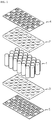
- FIG. 1 is an exploded perspective view showing a conventional battery module having cylindrical secondary batteries.
- a large number of cylindrical secondary batteries 1 are required to meet the required output voltage and charge/discharge capacity, and a frame is used to fix the cylindrical secondary batteries.
- the cylindrical secondary batteries 1 may be mounted and fixed between a top frame 2 and a bottom frame 3, which are provided to be coupled up and down.
- bus bars or metal plates 4, 5 are mounted to the top and bottom ends, respectively, so that the cylindrical secondary batteries may be connected in series and/or in parallel by the bus bars or the metal plates.
- the cylindrical secondary batteries should be arranged so that some cylindrical secondary batteries have positive electrode terminals facing upwards and some cylindrical secondary batteries have negative electrode terminals facing upward. Otherwise, a complicate conductor pattern should be provided on the top bus bar and the bottom bus bar, and the top bus bar and the bottom bus bar should be connected using separate components.
- the number of required cylindrical secondary batteries depends on the capacity and the output of the battery module.
- the frame for integrally fixing the cylindrical secondary batteries is used as in the conventional art, the frame need to be newly designed whenever the capacity of the battery module is changed.
- the cylindrical secondary battery recently has a function of preventing ignition and explosion by interrupting the current and eliminating the internal pressure during abnormal operation of the battery by using a current interruptive device (CID) mounted therein.
- CID current interruptive device
- the conventional battery module does not have any suitable means for preventing this problem.
- the present disclosure is designed to solve the problems of the related art, and therefore the present disclosure is directed to providing a cylindrical battery cell assembly, which has a space-efficient electrical connection structure and a chain ignition preventor and may be manufactured as a bundle unit having a specific capacity.
- the present disclosure is directed to providing a battery module, which may have various sizes and capacities by selectively combining the number of cylindrical battery cell assemblies and connecting them in series or in parallel.
- a cylindrical battery cell assembly comprising: a plurality of cylindrical battery cells each cylindrical battery cell having a first electrode terminal formed at a top end and a second electrode terminal at a bottom end thereof and arranged to stand up so that the electrode terminals having a same polarity face in the same direction; a cell holder configured to confine the plurality of cylindrical battery cells as a bundle unit; a first electrode connection member located at an upper portion of the cell holder to electrically connect the first electrode terminals; and a second electrode connection member configured to electrically connect the second electrode terminals, wherein the second electrode connection member includes: a second connection portion located at a lower portion of the cell holder and disposed to contact the second electrode terminals; and a rod-shaped second terminal portion extending vertically from the second connection portion through an empty space formed inside the cell holder so that a first end of the rod-shaped second terminal portion is disposed above the cell holder.
- the cell holder may include unit cell body covers, each unit cell cover having a cylindrical shape so that the plurality of cylindrical battery cells are inserted therein, respectively, and the unit cell body covers may be arranged in a triangular shape so that circumferential surfaces of neighboring unit cell body covers are attached to each other.
- the unit cell body covers may be provided so that at least three unit cell body covers are integrated, and the empty space is a region surrounded by the at least three unit cell body covers that are in contact with each other.
- the cell holder may further include a cell top cover having first electrode holes for exposing only the first electrode terminals of the plurality of cylindrical battery cells to the outside and provided to be mountable to top ends of the unit cell body covers.
- the unit cell body covers may be shorter than the plurality of cylindrical battery cells so that the plurality of cylindrical battery cells are exposed below the unit cell body covers.
- the cell top cover may further have a second terminal hole through which the first end of the rod-shaped second terminal portion passes.
- the cell holder may be made of mica or synthetic mica.
- the first electrode connection member may include first connection portions having a size corresponding to the first electrode holes and respectively fitted into the first electrode holes to contact the first electrode terminals; a conductor pattern configured to electrically connect the first connection portions; and a first terminal portion having one end protruding on the conductor pattern to the same height as the rod-shaped second terminal portion.
- a battery module comprising the plurality of cylindrical battery cell assemblies described above.
- the cylindrical battery cell assemblies may be arranged in a triangular shape when being viewed from above and closely arranged successively so that neighboring cylindrical battery cell assemblies are in a reversed form.
- the battery module may further comprise an insulation plate having insert holes formed at predetermined positions so that one ends of the first terminal portions and the rod-shaped second terminal portions are inserted therein, the insulation plate being configured to cover an upper portion of the cylindrical cell assemblies; and bus bars configured to selectively connect the first terminal portions and the rod-shaped second terminal portions.
- the battery module may further comprise a heatsink located at a lower portion of the plurality of cylindrical battery cell assemblies to absorb heat of the cylindrical battery cells; and a heat dissipation pad interposed between the cylindrical battery cell assemblies and the heatsink, wherein the heat dissipation pad has an engagement portion provided at an upper surface thereof to be engaged with a bottom portion of the cylindrical battery cell assembly.
- a battery pack comprising at least one battery module described above.
- a cylindrical battery cell assembly which has a space-efficient electrical connection structure and includes cylindrical battery cells having a specific capacity as a bundle unit.
- a battery module in various sizes and capacities by selectively combining the cylindrical battery cell assemblies and connecting them in series and/or in parallel.
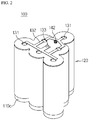
- FIG. 2 is a perspective view showing a cylindrical battery cell assembly according to an embodiment of the present disclosure
- FIG. 3 is an exploded perspective view showing the cylindrical battery cell assembly of FIG. 2 .
- a cylindrical battery cell assembly 100 includes a plurality of cylindrical battery cells 110, a cell holder 120, a first electrode connection member 130, and a second electrode connection member 140.
- the cylindrical battery cell 110 is a kind of can-type secondary battery in which an electrode assembly is embedded in a metal can.
- the metal can may be made of a lightweight conductive metal such as aluminum, stainless steel or alloys thereof.
- the cylindrical battery cell 110 may include a cylindrical battery can 110b, a jelly-roll type electrode assembly accommodated inside the battery can 110b, and a top cap 110a coupled to an upper portion of the battery can 110b.
- the top cap 110a may be connected to a positive electrode plate of the electrode assembly to serve as a positive electrode terminal
- a bottom end of the battery can 110b may be connected to a negative electrode plate of the electrode assembly to serve as a negative electrode terminal.
- the electrode terminals are formed at the top and bottom ends of the cylindrical battery cell 110, respectively.
- the cylindrical battery cells 110 may be disposed to stand up so that the cylindrical battery cells having the same polarity face in the same direction.
- the cylindrical battery cells 110 may all be arranged uniformly to face in one direction so that all positive electrode faces upward and all negative electrode faces downward.
- the arrangement of the cylindrical battery cells 110 may have a triangular form when being viewed from above.
- the cylindrical battery cell assembly 100 may include at least three unit cylindrical battery cells 110.
- six cylindrical battery cells 110 are arranged in a triangular form in total of, but more cylindrical battery cells 110, for example ten or fifteen cylindrical battery cells 110, may also be arranged in a triangular form.
- cylindrical battery cells 110 arranged in a triangular configuration.
- the triangular structure is disclosed as a preferred example, and as an alternative embodiment, the cylindrical battery cells 110 may be arranged in a rectangular or circular configuration when viewed from the top.
- the cell holder 120 is a component for accommodating and fixing the cylindrical battery cells 110 as a bundle unit and preventing the chain explosion of the cylindrical battery cells 110.
- the cell holder 120 of this embodiment includes unit cell body covers 121 and a cell top cover 123.
- the unit cell body covers 121 have a cylindrical shape and may be respectively coupled to the cylindrical battery cells 110 by fitting in a one-to-one relationship.
- the unit cell body covers 121 may be integrally formed in a triangular form so that circumferential surfaces of neighboring unit cell body covers 121 are attached to each other. That is, the unit cell body covers 121 may be designed to be suitable for the arrangement of the cylindrical battery cells 110.
- unit cell body covers 121 are provided as a single body to form a triangular form so that their circumferential surfaces are in contact with each other.
- the six cylindrical battery cells 110 may be inserted into the unit cell body covers 121. In this case, the six cylindrical battery cells 110 are confined in the unit cell body covers 121 to maintain the triangular form.
- the unit cell body cover 121 may be made of mica or synthetic mica. In this case, the unit cell body cover 121 may have sufficient heat resistance and electrical insulation. Thus, since the bodies of the six cylindrical battery cells 110 are covered by the unit cell body covers 121, even if any one of the cylindrical battery cells 110 is ignited or exploded, other cylindrical battery cells 110 may be protected, thereby preventing a chain ignition.
- the cell top cover 123 covers top ends of the cylindrical battery cells 110, namely the top cap region and may be made of mica or synthetic mica, similar to the unit cell body cover 121.
- the cell top cover 123 and the unit cell body cover 121 are separately manufactured and then mutually coupled by a clinching method for individual part production and assembly convenience.
- the cell top cover 123 and the unit cell body cover 121 may also be integrally manufactured.
- the top cap region 110a is likely to break first, and thus the flame is more likely to leak through the top end of the cylindrical battery cell 110 rather than the bottom end thereof.
- the unit cell body 110a and the top end of the cylindrical battery cells 110 are covered with the unit cell body cover 121 and cell top cover 123 to prevent the flame from propagating in an emergency.
- the lower portion of the cylindrical battery cells 110 is relatively unlikely to have a flame leakage, the lower portion is exposed to the outside and used as an area for cooling.
- the unit cell body covers 121 are formed to be slightly shorter than the cylindrical battery cells 110.
- the bottom portion 110c of the cylindrical battery cells 110 may be slightly exposed below the unit cell body covers 121, and the remaining portion may be covered by the cell holder 120.
- the first electrode connection member 130 is located at an upper portion of the unit cell holder 120 to electrically connect first electrode terminals respectively located at the top ends of the cylindrical battery cells 110, and the second electrode connection member 140 electrically connects second electrode terminals respectively located at the bottom ends of the cylindrical battery cells 110.
- the cylindrical battery cells 110 stands upright so that all positive electrode terminals face upward, the positive electrode terminals correspond to the first electrode terminals and the negative electrode terminals correspond to the second electrode terminals.
- the negative electrode terminals may serve as the first electrode terminals and the positive electrode terminals may serve as the second electrode terminals.
- the first electrode means a positive electrode and the second electrode means a negative electrode.
- the first electrode connection member 130 includes a first connection portion 131, a conductor pattern 132, and a first terminal portion 133.
- the first connection portion 131 is a portion that contacts the positive electrode of each cylindrical battery cell 110, namely a portion contacting the protruding region of the top cap 110a.
- the first connection portion 131 may be attached to the top cap 110a by welding.
- the cell top cover 123 further has first electrode holes 124, and the positive electrode terminals of the cylindrical battery cells 110 are respectively positioned below the first electrode holes 124.
- the first connection portion 131 may be formed in a size corresponding to the first electrode hole 124 and may be welded in a state of being inserted into the first electrode hole 124 to contact the positive electrode.
- the conductor pattern 132 is in the form of a thin metal plate intersecting in a plurality of directions and may be provided to electrically connect the first connection portions 131.
- the conductor pattern 132 may be provided to electrically connect the first connection portions 131.
- six first connection portions 131 in total may contact the positive electrode terminals of six cylindrical battery cells 110, and the six first connection portions 131 may be electrically connected with each other by the conductor pattern 132.
- the first terminal portion 133 serves as a positive electrode terminal of the cylindrical battery cells 110 and may have a predetermined thickness on the conductor pattern 132 to protrude upward, opposite to the first connection portion 131.
- the first terminal portion 133 may extend on the conductor pattern 132 to the same height as one end of a rod-shaped second terminal portion 142, explained later.
- the second electrode connection member 140 includes a second connection portion 141 and a rod-shaped second terminal portion 142.
- the second connection portion 141 is located at a lower portion of the cell holder 120 and may have a plate form with an area capable of contacting all of the negative electrode terminals of the cylindrical battery cells 110, respectively.
- the second connection portion 141 of this embodiment is provided in the form of a triangular plate where the bottom centers of the cylindrical battery cells 110 are located at three vertex regions.
- the second connection portion 141 in the form of a triangular plate may electrically connect the cylindrical battery cells 110 placed thereon and simultaneously support the cylindrical battery cells 110 integrally.
- the second connection portion 141 in the form of a triangular plate may be attached to the lower surface of the cylindrical battery cells 110 through a spot welding process.
- the spot welding may be performed at six places where the negative electrode portions of the cylindrical battery cells 110 are respectively in contact with the second connection portion 141.
- the rod-shaped second terminal portion 142 extends vertically from the second connection portion 141 through an empty space 122 formed inside the cell holder 120 so that one end of the rod-shaped second terminal portion 142 is disposed on the cell holder 120.
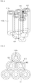
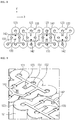
- the unit cell body covers 121 since the unit cell body covers 121 according to the present disclosure have a cylindrical shape and are arranged in a triangular form so that their circumferential surfaces are in contact with each other, it may be found that the empty space 122 is inevitably formed at the inner region of the unit cell body covers 121. That is, the empty space 122 may be specified as an area surrounded by at least three unit cell body covers 121 whose circumferential surfaces are in contact with each other.
- the rod-shaped second terminal portion 142 has a cylindrical shape, for example, to be inserted into the empty space 122, and is disposed inside the unit cell body covers 121.
- the cell top cover 123 further has a second terminal hole 125, one end of the rod-shaped second terminal portion 142 may be exposed above the cell top cover 123 through the second terminal hole 125. At this time, the rod-shaped second terminal portion 142 may extend to the same height as the first terminal portion 133 described above.
- the cylindrical battery cell assembly 100 may be prepared in a more compact design, and its peripheral space may be utilized more efficiently and more freely.
- the rod-shaped second terminal portion 142 may be disposed on the cell top cover 123 at the same height as the first terminal portion 133 to be adjacent thereto to function as a negative electrode terminal of the cylindrical battery cell assembly 100.
- the first terminal portion 133 may be specified as a positive electrode terminal
- the rod-shaped second terminal portion 142 may be specified as a negative electrode terminal. Since the positive electrode terminal and the negative electrode terminal are positioned adjacent to each other in the same direction in the cylindrical battery cell assembly 100 according to the present disclosure, the positive electrode terminal and the negative electrode terminal may be electrically connected to other components very simply.
- the cylindrical battery cell assembly 100 including the cylindrical battery cells 110 having a predetermined capacity and connected in parallel. If the cylindrical battery cell assemblies 100 are used, the battery module 10 may be manufactured in various shapes and sizes while ensuring simple electric connection.
- the battery module 10 including the cylindrical battery cell assemblies 100 described above as one component will be described with reference to FIGS 6 to 9 .
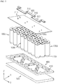
- the battery module 10 may include cylindrical battery cell assemblies 100, an insulation plate 200 covering an upper portion of the cylindrical battery cell assemblies 100, bus bars 300 for electrically connecting the cylindrical battery cell assemblies 100, and a heat dissipation pad 400 and a heatsink 500 for cooling the cylindrical battery cell assemblies 100.
- the number of cylindrical battery cell assemblies 100 may be predetermined according to the capacity and the output required for the battery module 10, and the cylindrical battery cell assemblies 100 may be closely adhered to each other successively inside the battery module 10.
- cylindrical battery cell assemblies 100a, 100b, 100c, 100d may be successively arranged in close contact with each other in the X-axis direction.
- the cylindrical battery cell assemblies 100 are arranged in a triangular form when being viewed from the above, and one cylindrical battery cell assembly 100 may closely contact another neighboring cylindrical battery cell assembly 100 in a symmetric or reverse pattern, successively.
- an additional cylindrical battery cell assembly 100 may be successively provided in the X-axis direction, or in the X-axis direction and in the Y-axis direction, in the same pattern as this embodiment so that the battery module 10 may have various shapes and sizes.
- the positive electrode terminals 133 and the negative electrode terminals 142 of the neighboring cylindrical battery cell assemblies 100 are also disposed reversely with respect to each other.
- the positive electrode terminals 133 and the negative electrode terminals 142 are alternately arranged in two rows along the X-axis direction.
- the bus bars 300 may be mounted in a simple pattern.
- the insulation plate 200 is made of, for example, a material with excellent insulation and heat resistance such as mica and may have a plate form with an area capable of covering the upper portion of the cylindrical battery cell assembly 100.
- the insulation plate 200 has insert holes 210 formed at predetermined positions.
- the positive electrode terminals 133 and the negative electrode terminals 142 of the cylindrical battery cell assemblies 100 are inserted into the insertion holes 210 of the insulation plate 200 and exposed above the insulation plate 200.
- One ends of the positive electrode terminals 133 and the negative electrode terminals 142 exposed above the insulation plate 200 may be welded to the bus bar 300 in a state of being interposed in the terminal connection holes 310 provided at both ends of the bus bar 300.
- a bus bar 300 may be connected to the negative electrode terminal 142 of the second cylindrical battery cell assembly 100b adjacent to the positive electrode terminal 133 of the first cylindrical battery cell assembly 100a in the X-axis direction and be connected to the negative electrode terminal 142 of the third cylindrical battery cell assembly 100c adjacent to the positive electrode terminal 133 of the second cylindrical battery cell assembly 100b in the X-axis direction.
- a bus bar 300 may be connected to the positive electrode terminal 133 of the third cylindrical battery cell assembly 100c and the negative electrode terminal 142 of the fourth cylindrical battery cell assembly 100d.
- the positions of the positive electrode terminal 133 and the negative electrode terminal 142 exposed above the cell top cover 123 may be changed as desired in each cylindrical battery cell assembly 100.
- the two kinds of cylindrical battery cell assemblies 100 having positive electrode terminals 133 and negative electrode terminals 142 located at opposite sides based on the Y-axis direction are used, even though the two kinds of cylindrical battery cell assemblies 100 are arranged so that neighboring cylindrical battery cell assemblies 100 have reverse shapes, the positive electrode terminals 133 and the negative electrode terminals 142 of the cylindrical battery cell assemblies 100 are not arranged reversely with respect to each other.
- the bus bar 300 having a straight form may be used as it is for parallel connection, which makes it easier to mount the bus bar 300.
- the bottom portion 110c of the cylindrical battery cell assembly 100 namely the bottom portions 110c of the cylindrical battery cells 110, may be utilized as an area for cooling.
- the heatsink 500 is disposed at the lower portion of the cylindrical battery cell assembly 100 so that the heat generated from the cylindrical battery cells 110 are emitted to the outside through the heatsink 500.
- the heatsink 500 may be a component that allows a coolant to pass through a flow path therein so that the cylindrical battery cells 110 are indirectly cooled by absorbing the heat of the cylindrical battery cells 110 by means of thermal contact.
- the heat dissipation pad 400 may be further interposed between the cylindrical battery cell assemblies 100 and the heatsink 500.
- the heat dissipation pad 400 may further have an engagement portion 410 formed at an upper surface thereof to be engaged with the bottom portion of the cylindrical battery cell assembly 100 so as to enhance the adhering force.
- the bottom portion 110c of the cylindrical battery cells exposed below the cell holder 120 may be inserted into the engagement portion 410 to be engaged therewith.
- heat dissipation pad 400 If the heat dissipation pad 400 is used, an air layer created by the difference in surface roughness between the cylindrical battery cells 110 and the heatsink 500 may be eliminated, it is possible to improve the heat transfer efficiency and more securely fix the cylindrical battery cell assemblies 100.
- the battery module 10 which has a space-efficient electric connection structure and is safe since it is possible to prevent the occurrence of chain firing of the neighboring cylindrical battery cells 110 even though any one of the cylindrical battery cells 110 is ignited.
- the number of the cylindrical battery cell assemblies 100 may be increased or decreased to manufacture the battery module 10 in various sizes and capacities.
- a battery pack according to the present disclosure may include at least one battery modules 10 of the present disclosure.
- the battery pack according to the present disclosure may further include a pack case for accommodating the battery module 10, and various devices for controlling charge and discharge of the battery module 10 such as a battery management system (BMS), a current sensor, a fuse or the like.
- BMS battery management system
Landscapes
- Chemical & Material Sciences (AREA)
- Chemical Kinetics & Catalysis (AREA)
- Electrochemistry (AREA)
- General Chemical & Material Sciences (AREA)
- Engineering & Computer Science (AREA)
- Manufacturing & Machinery (AREA)
- Inorganic Chemistry (AREA)
- Life Sciences & Earth Sciences (AREA)
- Biophysics (AREA)
- Connection Of Batteries Or Terminals (AREA)
- Battery Mounting, Suspending (AREA)
- Secondary Cells (AREA)
Applications Claiming Priority (2)
| Application Number | Priority Date | Filing Date | Title |
|---|---|---|---|
| KR1020170179817A KR102288405B1 (ko) | 2017-12-26 | 2017-12-26 | 공간 활용성과 안전성이 향상된 원통형 전지셀 조립체 및 이를 포함하는 배터리 모듈 |
| PCT/KR2018/015342 WO2019132291A1 (fr) | 2017-12-26 | 2018-12-05 | Ensemble de cellules de batterie cylindriques à utilisation d'espace et sécurité améliorées et module de batterie le comprenant |
Publications (3)
| Publication Number | Publication Date |
|---|---|
| EP3664187A1 true EP3664187A1 (fr) | 2020-06-10 |
| EP3664187A4 EP3664187A4 (fr) | 2020-10-28 |
| EP3664187B1 EP3664187B1 (fr) | 2022-08-31 |
Family
ID=67067750
Family Applications (1)
| Application Number | Title | Priority Date | Filing Date |
|---|---|---|---|
| EP18894711.3A Active EP3664187B1 (fr) | 2017-12-26 | 2018-12-05 | Ensemble de cellules de batterie cylindriques à utilisation d'espace et sécurité améliorées et module de batterie le comprenant |
Country Status (9)
| Country | Link |
|---|---|
| US (1) | US11139529B2 (fr) |
| EP (1) | EP3664187B1 (fr) |
| JP (1) | JP7045597B2 (fr) |
| KR (1) | KR102288405B1 (fr) |
| CN (1) | CN110710019B (fr) |
| ES (1) | ES2928339T3 (fr) |
| HU (1) | HUE059890T2 (fr) |
| PL (1) | PL3664187T3 (fr) |
| WO (1) | WO2019132291A1 (fr) |
Families Citing this family (33)
| Publication number | Priority date | Publication date | Assignee | Title |
|---|---|---|---|---|
| EP3734708B1 (fr) * | 2017-12-26 | 2024-02-07 | Panasonic Intellectual Property Management Co., Ltd. | Module de piles |
| KR102698844B1 (ko) * | 2018-12-04 | 2024-08-23 | 주식회사 엘지에너지솔루션 | 전지팩 |
| CN112310542B (zh) | 2019-12-27 | 2022-01-11 | 宁德时代新能源科技股份有限公司 | 一种连接组件、电池模块、电池组、装置以及安装方法 |
| KR102809521B1 (ko) | 2020-02-13 | 2025-05-19 | 주식회사 엘지에너지솔루션 | 레일형 소켓이 구비된 전지 모듈 및 이를 포함하는 전지 팩 |
| KR102752085B1 (ko) * | 2020-03-26 | 2025-01-09 | 엘에스머트리얼즈 주식회사 | 울트라 캐패시터 모듈 |
| KR102718016B1 (ko) | 2020-05-07 | 2024-10-15 | 컨템포러리 엠퍼렉스 테크놀로지 (홍콩) 리미티드 | 전지 모듈, 전지 팩, 전지 모듈을 전원으로 사용하는 기기 및 전지 모듈의 제조 방법 |
| KR102859368B1 (ko) | 2020-06-04 | 2025-09-15 | 주식회사 엘지에너지솔루션 | 전도성 접착제가 부가된 연결 부재를 포함하는 원통형 전지모듈 및 이의 제조방법 |
| WO2021256878A1 (fr) * | 2020-06-17 | 2021-12-23 | 주식회사 엘지에너지솔루션 | Module de batterie, bloc-batterie comprenant ce dernier, véhicule, et procédé de fabrication de bloc-batterie |
| KR102809421B1 (ko) * | 2020-06-30 | 2025-05-16 | 주식회사 엘지에너지솔루션 | 배터리 모듈, 그것을 포함하는 배터리 팩, 및 자동차 |
| KR102242906B1 (ko) * | 2020-09-17 | 2021-04-21 | 국방과학연구소 | 열전지, 열전지 모듈 및 열전지 시스템 |
| KR102859092B1 (ko) * | 2020-09-17 | 2025-09-12 | 주식회사 엘지에너지솔루션 | 전지모듈 |
| CA3194251A1 (fr) * | 2020-10-01 | 2022-04-07 | William J. Doak | Attenuation de la propagation d'un emballement thermique dans des blocs-batteries au lithium-ion |
| KR102943040B1 (ko) * | 2020-10-22 | 2026-03-24 | 주식회사 엘지에너지솔루션 | 배터리 팩 및 이의 제조방법 |
| KR102481274B1 (ko) * | 2020-12-28 | 2022-12-26 | 주식회사 유라코퍼레이션 | 배터리 셀 모듈 |
| CA3202317A1 (fr) * | 2021-01-19 | 2022-07-28 | Lg Energy Solution, Ltd. | Batterie, collecteur de courant applique a celle-ci, et bloc-batterie et vehicule les comprenant |
| US12132227B2 (en) | 2021-01-19 | 2024-10-29 | Lg Energy Solution, Ltd. | Battery, and battery pack and vehicle comprising the same |
| KR20220118955A (ko) * | 2021-02-19 | 2022-08-26 | 주식회사 엘지에너지솔루션 | 배터리, 그리고 이를 포함하는 배터리 팩 및 자동차 |
| US12407028B2 (en) | 2021-02-19 | 2025-09-02 | Lg Energy Solution, Ltd. | Electrode assembly, battery, and battery pack and vehicle including the same |
| CN116349066A (zh) * | 2021-02-19 | 2023-06-27 | 株式会社Lg新能源 | 电池、以及电池组和包括该电池组的车辆 |
| JP7721647B2 (ja) * | 2021-02-19 | 2025-08-12 | エルジー エナジー ソリューション リミテッド | バッテリー、それを含むバッテリーパック及び自動車 |
| US20220376339A1 (en) * | 2021-05-24 | 2022-11-24 | Samsung Sdi Co., Ltd. | Battery pack |
| US11990594B2 (en) | 2021-06-21 | 2024-05-21 | Rivian Ip Holdings, Llc | Cell module barrier sheets for thermal propagation resistance |
| CA3233777A1 (fr) * | 2021-10-11 | 2023-04-20 | Vu Phan | Module de batterie |
| US12463283B2 (en) * | 2021-10-12 | 2025-11-04 | Lg Energy Solution, Ltd. | Battery pack and vehicle including the same |
| HUE071772T2 (hu) | 2021-10-14 | 2025-09-28 | Lg Energy Solution Ltd | Akkumulátor, az arra alkalmazott áramgyûjtõ lemez, valamint az azt tartalmazó akkumulátorcsomag és jármû |
| JP7685293B2 (ja) * | 2021-12-28 | 2025-05-29 | リベスト インコーポレイテッド | バッテリの外装材にパターンを形成する装置及び方法 |
| DE102022127517A1 (de) * | 2022-10-19 | 2024-04-25 | Alfred Kärcher SE & Co. KG | Elektrische Energiespeichervorrichtung und Elektrogerätesystem |
| CN116345072B (zh) * | 2023-04-28 | 2026-02-27 | 合肥国轩高科动力能源有限公司 | 一种双卷芯圆柱锂电池结构 |
| CN220699521U (zh) | 2023-05-19 | 2024-04-02 | 米沃奇电动工具公司 | 动力工具 |
| WO2025114885A1 (fr) * | 2023-12-01 | 2025-06-05 | SES (Shanghai) Co., Ltd. | Système et procédé permettant d'agencer des éléments de batterie sur la base de groupements de nombres premiers d'éléments raccordées en parallèle |
| KR20250151824A (ko) | 2024-04-15 | 2025-10-22 | 주식회사 세미콘테스트 | 원통형 배터리 조립체 |
| CN118398983B (zh) * | 2024-06-25 | 2024-09-03 | 山东嘉泰能源集团有限公司 | 一种便于装配的镍氢电池组 |
| KR20260013554A (ko) * | 2024-07-22 | 2026-01-29 | 주식회사 엘지에너지솔루션 | 배터리 어셈블리 |
Family Cites Families (31)
| Publication number | Priority date | Publication date | Assignee | Title |
|---|---|---|---|---|
| JP2823613B2 (ja) * | 1989-12-05 | 1998-11-11 | 日本碍子株式会社 | 円筒型ナトリウム―硫黄電池スタック |
| JP2003217560A (ja) | 2002-01-21 | 2003-07-31 | Japan Storage Battery Co Ltd | 円筒型組電池 |
| JP2008218210A (ja) * | 2007-03-05 | 2008-09-18 | Lenovo Singapore Pte Ltd | 電池パックおよび携帯式電子機器 |
| JP5241182B2 (ja) * | 2007-09-11 | 2013-07-17 | 三洋電機株式会社 | 組電池 |
| KR100938896B1 (ko) * | 2007-10-26 | 2010-01-27 | 삼성에스디아이 주식회사 | 배터리 팩 |
| JP2009211908A (ja) * | 2008-03-04 | 2009-09-17 | Panasonic Corp | 電池およびそれを用いた電池パック |
| BRPI0911250A2 (pt) * | 2008-04-14 | 2015-10-06 | A123 Systems Inc | design de módulo de bateria alojado de voltagem flexível |
| DE102009033076B4 (de) * | 2009-07-03 | 2019-06-27 | Volkswagen Ag | Verfahren zur Anordnung von zylinderförmigen Batteriezellen zu einem Batteriemodul für ein Fahrzeug sowie entsprechend ausgestaltete(s) Batteriemodul, Batteriemodulanordnung und Fahrzeug |
| US8730085B2 (en) | 2010-08-26 | 2014-05-20 | Lawrence Livermore National Security, Llc | Spot restoration for GPR image post-processing |
| CA2873057C (fr) | 2011-05-09 | 2020-02-25 | University Of South Florida | Utilisation d'esters de cetone dans la prevention de la toxicite de l'oxygene sur le systeme nerveux central |
| JPWO2012164837A1 (ja) * | 2011-05-31 | 2015-02-23 | パナソニック株式会社 | 電源装置 |
| JP2014170613A (ja) | 2011-06-28 | 2014-09-18 | Panasonic Corp | 電池モジュール |
| JP5824612B2 (ja) | 2011-07-29 | 2015-11-25 | パナソニックIpマネジメント株式会社 | 電池モジュール |
| JP5803513B2 (ja) * | 2011-09-29 | 2015-11-04 | ソニー株式会社 | 電池パック、蓄電システム、電子機器および電動車両 |
| JP5979508B2 (ja) * | 2011-11-30 | 2016-08-24 | パナソニックIpマネジメント株式会社 | 電池パック |
| US9054367B2 (en) * | 2012-02-01 | 2015-06-09 | Samsung Sdi Co., Ltd. | Rechargeable battery assembly and pack including the same |
| WO2014083600A1 (fr) | 2012-11-30 | 2014-06-05 | トヨタ自動車株式会社 | Appareil de stockage d'énergie électrique |
| US9853276B2 (en) | 2013-01-11 | 2017-12-26 | Panasonic Intellectual Property Management Co., Ltd. | Battery pack |
| US20140234683A1 (en) * | 2013-02-19 | 2014-08-21 | Faster Faster, Inc. | Thermal Insulation of Battery Cells |
| KR101678532B1 (ko) * | 2013-02-21 | 2016-11-22 | 삼성에스디아이 주식회사 | 배터리 모듈 |
| DE102013207536B4 (de) * | 2013-04-25 | 2019-02-07 | Lisa Dräxlmaier GmbH | Zellblock mit Zellfixierung für eine Batterie und Verfahren zum Bestücken eines Zellblocks |
| CA2947765A1 (fr) | 2014-05-21 | 2015-11-26 | Thermal Ceramics, Inc. | Materiaux d'isolation passive |
| TW201633585A (zh) | 2014-12-15 | 2016-09-16 | A123系統有限責任公司 | 電池總成、電池系統以及車輛電池 |
| KR101797693B1 (ko) * | 2014-12-26 | 2017-11-15 | 주식회사 엘지화학 | 밀착 절곡부가 형성되어 있는 전지셀 접속부재를 사용하여 제조되는 전지팩 |
| JP6248972B2 (ja) * | 2015-03-23 | 2017-12-20 | トヨタ自動車株式会社 | 電池パック |
| WO2017088996A1 (fr) * | 2015-11-24 | 2017-06-01 | Nordfels Gmbh | Barre conductrice et module de batterie pourvu d'une telle barre conductrice |
| CN105514312A (zh) * | 2015-12-08 | 2016-04-20 | 合普新能源科技有限公司 | 一种车用锂离子电池模块及其半成品模块 |
| KR102459622B1 (ko) * | 2015-12-29 | 2022-10-27 | 삼성에스디아이 주식회사 | 배터리 팩 |
| CN205609697U (zh) | 2016-03-22 | 2016-09-28 | 深圳市沃特玛电池有限公司 | 电池组 |
| JP6769176B2 (ja) | 2016-08-30 | 2020-10-14 | トヨタ自動車株式会社 | 電池モジュール |
| CN107170935A (zh) * | 2017-06-30 | 2017-09-15 | 格林美(武汉)新能源汽车服务有限公司 | 防火阻燃动力电池模块 |
-
2017
- 2017-12-26 KR KR1020170179817A patent/KR102288405B1/ko active Active
-
2018
- 2018-12-05 HU HUE18894711A patent/HUE059890T2/hu unknown
- 2018-12-05 WO PCT/KR2018/015342 patent/WO2019132291A1/fr not_active Ceased
- 2018-12-05 EP EP18894711.3A patent/EP3664187B1/fr active Active
- 2018-12-05 PL PL18894711.3T patent/PL3664187T3/pl unknown
- 2018-12-05 US US16/619,407 patent/US11139529B2/en active Active
- 2018-12-05 CN CN201880036407.6A patent/CN110710019B/zh active Active
- 2018-12-05 JP JP2019566790A patent/JP7045597B2/ja active Active
- 2018-12-05 ES ES18894711T patent/ES2928339T3/es active Active
Also Published As
| Publication number | Publication date |
|---|---|
| US11139529B2 (en) | 2021-10-05 |
| CN110710019A (zh) | 2020-01-17 |
| CN110710019B (zh) | 2022-12-23 |
| KR102288405B1 (ko) | 2021-08-09 |
| JP2020522850A (ja) | 2020-07-30 |
| HUE059890T2 (hu) | 2023-01-28 |
| ES2928339T3 (es) | 2022-11-17 |
| JP7045597B2 (ja) | 2022-04-01 |
| KR20190078094A (ko) | 2019-07-04 |
| PL3664187T3 (pl) | 2022-10-31 |
| EP3664187B1 (fr) | 2022-08-31 |
| US20200127249A1 (en) | 2020-04-23 |
| WO2019132291A1 (fr) | 2019-07-04 |
| EP3664187A4 (fr) | 2020-10-28 |
Similar Documents
| Publication | Publication Date | Title |
|---|---|---|
| US11139529B2 (en) | Cylindrical battery cell assembly with improved space utilization and safety, and battery module comprising same | |
| US11462799B2 (en) | Battery module having gas discharge structure | |
| US12525682B2 (en) | Battery module including flame-retardant sheet, and battery rack and energy storage system including the same | |
| US20230246262A1 (en) | Battery module and battery pack comprising same | |
| ES2482114T3 (es) | Procedimiento para la preparación de un módulo de bateria secundaria | |
| EP3671945B1 (fr) | Bloc-batterie | |
| EP2482361B1 (fr) | Bloc batterie | |
| US11424502B2 (en) | Battery pack | |
| CN108604653A (zh) | 电池组 | |
| KR20190087744A (ko) | 방열 및 연쇄발화 방지 구조를 구비한 멀티 레이어 원통형 전지모듈 및 이를 포함하는 전지팩 | |
| US12183952B2 (en) | Battery pack with enhanced structure for preventing short circuit and shock | |
| WO2013021573A1 (fr) | Bloc de batteries et module de batteries le contenant | |
| KR102587699B1 (ko) | 배터리 팩 | |
| JP5929731B2 (ja) | 蓄電装置及び接続部材 | |
| US20180323412A1 (en) | Battery module, and battery pack and vehicle comprising same | |
| KR20220151560A (ko) | 버스바 어셈블리, 이를 포함하는 배터리 팩 및 자동차 | |
| EP4432446A1 (fr) | Module de batterie et bloc-batterie le comprenant et véhicule le comprenant | |
| KR20240099037A (ko) | 배터리 모듈 및 이를 포함하는 배터리 팩 | |
| KR20150134836A (ko) | 관통구가 형성된 pcb를 포함하는 전지팩 | |
| CN118202514A (zh) | 电池模块以及包括该电池模块的电池组和车辆 | |
| KR20240080355A (ko) | 배터리 패키지 |
Legal Events
| Date | Code | Title | Description |
|---|---|---|---|
| STAA | Information on the status of an ep patent application or granted ep patent |
Free format text: STATUS: THE INTERNATIONAL PUBLICATION HAS BEEN MADE |
|
| PUAI | Public reference made under article 153(3) epc to a published international application that has entered the european phase |
Free format text: ORIGINAL CODE: 0009012 |
|
| STAA | Information on the status of an ep patent application or granted ep patent |
Free format text: STATUS: REQUEST FOR EXAMINATION WAS MADE |
|
| 17P | Request for examination filed |
Effective date: 20200303 |
|
| AK | Designated contracting states |
Kind code of ref document: A1 Designated state(s): AL AT BE BG CH CY CZ DE DK EE ES FI FR GB GR HR HU IE IS IT LI LT LU LV MC MK MT NL NO PL PT RO RS SE SI SK SM TR |
|
| AX | Request for extension of the european patent |
Extension state: BA ME |
|
| A4 | Supplementary search report drawn up and despatched |
Effective date: 20200925 |
|
| RIC1 | Information provided on ipc code assigned before grant |
Ipc: H01M 10/655 20140101ALI20200921BHEP Ipc: H01M 2/10 20060101AFI20200921BHEP Ipc: H01M 10/6551 20140101ALI20200921BHEP Ipc: H01M 2/20 20060101ALI20200921BHEP Ipc: H01M 10/643 20140101ALI20200921BHEP |
|
| DAV | Request for validation of the european patent (deleted) | ||
| DAX | Request for extension of the european patent (deleted) | ||
| STAA | Information on the status of an ep patent application or granted ep patent |
Free format text: STATUS: EXAMINATION IS IN PROGRESS |
|
| 17Q | First examination report despatched |
Effective date: 20210426 |
|
| RAP1 | Party data changed (applicant data changed or rights of an application transferred) |
Owner name: LG ENERGY SOLUTION LTD. |
|
| REG | Reference to a national code |
Ref country code: DE Ref legal event code: R079 Ref document number: 602018040178 Country of ref document: DE Free format text: PREVIOUS MAIN CLASS: H01M0002100000 Ipc: H01M0050258000 |
|
| RAP3 | Party data changed (applicant data changed or rights of an application transferred) |
Owner name: LG ENERGY SOLUTION, LTD. |
|
| RIC1 | Information provided on ipc code assigned before grant |
Ipc: H01M 50/502 20210101ALI20220318BHEP Ipc: H01M 10/613 20140101ALI20220318BHEP Ipc: H01M 50/213 20210101ALI20220318BHEP Ipc: H01M 50/258 20210101AFI20220318BHEP |
|
| GRAP | Despatch of communication of intention to grant a patent |
Free format text: ORIGINAL CODE: EPIDOSNIGR1 |
|
| STAA | Information on the status of an ep patent application or granted ep patent |
Free format text: STATUS: GRANT OF PATENT IS INTENDED |
|
| INTG | Intention to grant announced |
Effective date: 20220523 |
|
| GRAS | Grant fee paid |
Free format text: ORIGINAL CODE: EPIDOSNIGR3 |
|
| GRAA | (expected) grant |
Free format text: ORIGINAL CODE: 0009210 |
|
| STAA | Information on the status of an ep patent application or granted ep patent |
Free format text: STATUS: THE PATENT HAS BEEN GRANTED |
|
| AK | Designated contracting states |
Kind code of ref document: B1 Designated state(s): AL AT BE BG CH CY CZ DE DK EE ES FI FR GB GR HR HU IE IS IT LI LT LU LV MC MK MT NL NO PL PT RO RS SE SI SK SM TR |
|
| REG | Reference to a national code |
Ref country code: CH Ref legal event code: EP Ref country code: GB Ref legal event code: FG4D |
|
| REG | Reference to a national code |
Ref country code: AT Ref legal event code: REF Ref document number: 1515968 Country of ref document: AT Kind code of ref document: T Effective date: 20220915 |
|
| REG | Reference to a national code |
Ref country code: DE Ref legal event code: R096 Ref document number: 602018040178 Country of ref document: DE |
|
| REG | Reference to a national code |
Ref country code: IE Ref legal event code: FG4D |
|
| REG | Reference to a national code |
Ref country code: SE Ref legal event code: TRGR |
|
| REG | Reference to a national code |
Ref country code: ES Ref legal event code: FG2A Ref document number: 2928339 Country of ref document: ES Kind code of ref document: T3 Effective date: 20221117 |
|
| REG | Reference to a national code |
Ref country code: LT Ref legal event code: MG9D |
|
| REG | Reference to a national code |
Ref country code: NL Ref legal event code: MP Effective date: 20220831 |
|
| REG | Reference to a national code |
Ref country code: HU Ref legal event code: AG4A Ref document number: E059890 Country of ref document: HU |
|
| PG25 | Lapsed in a contracting state [announced via postgrant information from national office to epo] |
Ref country code: RS Free format text: LAPSE BECAUSE OF FAILURE TO SUBMIT A TRANSLATION OF THE DESCRIPTION OR TO PAY THE FEE WITHIN THE PRESCRIBED TIME-LIMIT Effective date: 20220831 Ref country code: NO Free format text: LAPSE BECAUSE OF FAILURE TO SUBMIT A TRANSLATION OF THE DESCRIPTION OR TO PAY THE FEE WITHIN THE PRESCRIBED TIME-LIMIT Effective date: 20221130 Ref country code: LV Free format text: LAPSE BECAUSE OF FAILURE TO SUBMIT A TRANSLATION OF THE DESCRIPTION OR TO PAY THE FEE WITHIN THE PRESCRIBED TIME-LIMIT Effective date: 20220831 Ref country code: LT Free format text: LAPSE BECAUSE OF FAILURE TO SUBMIT A TRANSLATION OF THE DESCRIPTION OR TO PAY THE FEE WITHIN THE PRESCRIBED TIME-LIMIT Effective date: 20220831 Ref country code: FI Free format text: LAPSE BECAUSE OF FAILURE TO SUBMIT A TRANSLATION OF THE DESCRIPTION OR TO PAY THE FEE WITHIN THE PRESCRIBED TIME-LIMIT Effective date: 20220831 |
|
| REG | Reference to a national code |
Ref country code: AT Ref legal event code: MK05 Ref document number: 1515968 Country of ref document: AT Kind code of ref document: T Effective date: 20220831 |
|
| PG25 | Lapsed in a contracting state [announced via postgrant information from national office to epo] |
Ref country code: IS Free format text: LAPSE BECAUSE OF FAILURE TO SUBMIT A TRANSLATION OF THE DESCRIPTION OR TO PAY THE FEE WITHIN THE PRESCRIBED TIME-LIMIT Effective date: 20221231 Ref country code: HR Free format text: LAPSE BECAUSE OF FAILURE TO SUBMIT A TRANSLATION OF THE DESCRIPTION OR TO PAY THE FEE WITHIN THE PRESCRIBED TIME-LIMIT Effective date: 20220831 Ref country code: GR Free format text: LAPSE BECAUSE OF FAILURE TO SUBMIT A TRANSLATION OF THE DESCRIPTION OR TO PAY THE FEE WITHIN THE PRESCRIBED TIME-LIMIT Effective date: 20221201 |
|
| PG25 | Lapsed in a contracting state [announced via postgrant information from national office to epo] |
Ref country code: SM Free format text: LAPSE BECAUSE OF FAILURE TO SUBMIT A TRANSLATION OF THE DESCRIPTION OR TO PAY THE FEE WITHIN THE PRESCRIBED TIME-LIMIT Effective date: 20220831 Ref country code: RO Free format text: LAPSE BECAUSE OF FAILURE TO SUBMIT A TRANSLATION OF THE DESCRIPTION OR TO PAY THE FEE WITHIN THE PRESCRIBED TIME-LIMIT Effective date: 20220831 Ref country code: PT Free format text: LAPSE BECAUSE OF FAILURE TO SUBMIT A TRANSLATION OF THE DESCRIPTION OR TO PAY THE FEE WITHIN THE PRESCRIBED TIME-LIMIT Effective date: 20230102 Ref country code: DK Free format text: LAPSE BECAUSE OF FAILURE TO SUBMIT A TRANSLATION OF THE DESCRIPTION OR TO PAY THE FEE WITHIN THE PRESCRIBED TIME-LIMIT Effective date: 20220831 Ref country code: CZ Free format text: LAPSE BECAUSE OF FAILURE TO SUBMIT A TRANSLATION OF THE DESCRIPTION OR TO PAY THE FEE WITHIN THE PRESCRIBED TIME-LIMIT Effective date: 20220831 Ref country code: AT Free format text: LAPSE BECAUSE OF FAILURE TO SUBMIT A TRANSLATION OF THE DESCRIPTION OR TO PAY THE FEE WITHIN THE PRESCRIBED TIME-LIMIT Effective date: 20220831 |
|
| PG25 | Lapsed in a contracting state [announced via postgrant information from national office to epo] |
Ref country code: SK Free format text: LAPSE BECAUSE OF FAILURE TO SUBMIT A TRANSLATION OF THE DESCRIPTION OR TO PAY THE FEE WITHIN THE PRESCRIBED TIME-LIMIT Effective date: 20220831 Ref country code: EE Free format text: LAPSE BECAUSE OF FAILURE TO SUBMIT A TRANSLATION OF THE DESCRIPTION OR TO PAY THE FEE WITHIN THE PRESCRIBED TIME-LIMIT Effective date: 20220831 |
|
| REG | Reference to a national code |
Ref country code: DE Ref legal event code: R097 Ref document number: 602018040178 Country of ref document: DE |
|
| P01 | Opt-out of the competence of the unified patent court (upc) registered |
Effective date: 20230512 |
|
| PG25 | Lapsed in a contracting state [announced via postgrant information from national office to epo] |
Ref country code: NL Free format text: LAPSE BECAUSE OF FAILURE TO SUBMIT A TRANSLATION OF THE DESCRIPTION OR TO PAY THE FEE WITHIN THE PRESCRIBED TIME-LIMIT Effective date: 20220831 Ref country code: AL Free format text: LAPSE BECAUSE OF FAILURE TO SUBMIT A TRANSLATION OF THE DESCRIPTION OR TO PAY THE FEE WITHIN THE PRESCRIBED TIME-LIMIT Effective date: 20220831 |
|
| PLBE | No opposition filed within time limit |
Free format text: ORIGINAL CODE: 0009261 |
|
| STAA | Information on the status of an ep patent application or granted ep patent |
Free format text: STATUS: NO OPPOSITION FILED WITHIN TIME LIMIT |
|
| REG | Reference to a national code |
Ref country code: CH Ref legal event code: PL |
|
| 26N | No opposition filed |
Effective date: 20230601 |
|
| REG | Reference to a national code |
Ref country code: BE Ref legal event code: MM Effective date: 20221231 |
|
| PG25 | Lapsed in a contracting state [announced via postgrant information from national office to epo] |
Ref country code: SI Free format text: LAPSE BECAUSE OF FAILURE TO SUBMIT A TRANSLATION OF THE DESCRIPTION OR TO PAY THE FEE WITHIN THE PRESCRIBED TIME-LIMIT Effective date: 20220831 Ref country code: LU Free format text: LAPSE BECAUSE OF NON-PAYMENT OF DUE FEES Effective date: 20221205 |
|
| PG25 | Lapsed in a contracting state [announced via postgrant information from national office to epo] |
Ref country code: LI Free format text: LAPSE BECAUSE OF NON-PAYMENT OF DUE FEES Effective date: 20221231 Ref country code: IE Free format text: LAPSE BECAUSE OF NON-PAYMENT OF DUE FEES Effective date: 20221205 Ref country code: CH Free format text: LAPSE BECAUSE OF NON-PAYMENT OF DUE FEES Effective date: 20221231 |
|
| PG25 | Lapsed in a contracting state [announced via postgrant information from national office to epo] |
Ref country code: BE Free format text: LAPSE BECAUSE OF NON-PAYMENT OF DUE FEES Effective date: 20221231 |
|
| PG25 | Lapsed in a contracting state [announced via postgrant information from national office to epo] |
Ref country code: CY Free format text: LAPSE BECAUSE OF FAILURE TO SUBMIT A TRANSLATION OF THE DESCRIPTION OR TO PAY THE FEE WITHIN THE PRESCRIBED TIME-LIMIT Effective date: 20220831 |
|
| PG25 | Lapsed in a contracting state [announced via postgrant information from national office to epo] |
Ref country code: MK Free format text: LAPSE BECAUSE OF FAILURE TO SUBMIT A TRANSLATION OF THE DESCRIPTION OR TO PAY THE FEE WITHIN THE PRESCRIBED TIME-LIMIT Effective date: 20220831 Ref country code: IT Free format text: LAPSE BECAUSE OF FAILURE TO SUBMIT A TRANSLATION OF THE DESCRIPTION OR TO PAY THE FEE WITHIN THE PRESCRIBED TIME-LIMIT Effective date: 20220831 |
|
| PG25 | Lapsed in a contracting state [announced via postgrant information from national office to epo] |
Ref country code: MC Free format text: LAPSE BECAUSE OF FAILURE TO SUBMIT A TRANSLATION OF THE DESCRIPTION OR TO PAY THE FEE WITHIN THE PRESCRIBED TIME-LIMIT Effective date: 20220831 |
|
| PG25 | Lapsed in a contracting state [announced via postgrant information from national office to epo] |
Ref country code: MC Free format text: LAPSE BECAUSE OF FAILURE TO SUBMIT A TRANSLATION OF THE DESCRIPTION OR TO PAY THE FEE WITHIN THE PRESCRIBED TIME-LIMIT Effective date: 20220831 |
|
| PG25 | Lapsed in a contracting state [announced via postgrant information from national office to epo] |
Ref country code: BG Free format text: LAPSE BECAUSE OF FAILURE TO SUBMIT A TRANSLATION OF THE DESCRIPTION OR TO PAY THE FEE WITHIN THE PRESCRIBED TIME-LIMIT Effective date: 20220831 |
|
| PG25 | Lapsed in a contracting state [announced via postgrant information from national office to epo] |
Ref country code: MT Free format text: LAPSE BECAUSE OF FAILURE TO SUBMIT A TRANSLATION OF THE DESCRIPTION OR TO PAY THE FEE WITHIN THE PRESCRIBED TIME-LIMIT Effective date: 20220831 |
|
| PG25 | Lapsed in a contracting state [announced via postgrant information from national office to epo] |
Ref country code: TR Free format text: LAPSE BECAUSE OF FAILURE TO SUBMIT A TRANSLATION OF THE DESCRIPTION OR TO PAY THE FEE WITHIN THE PRESCRIBED TIME-LIMIT Effective date: 20220831 |
|
| PGFP | Annual fee paid to national office [announced via postgrant information from national office to epo] |
Ref country code: DE Payment date: 20251120 Year of fee payment: 8 |
|
| PGFP | Annual fee paid to national office [announced via postgrant information from national office to epo] |
Ref country code: GB Payment date: 20251120 Year of fee payment: 8 |
|
| PGFP | Annual fee paid to national office [announced via postgrant information from national office to epo] |
Ref country code: HU Payment date: 20251216 Year of fee payment: 8 Ref country code: FR Payment date: 20251125 Year of fee payment: 8 |
|
| PGFP | Annual fee paid to national office [announced via postgrant information from national office to epo] |
Ref country code: SE Payment date: 20251121 Year of fee payment: 8 |
|
| PGFP | Annual fee paid to national office [announced via postgrant information from national office to epo] |
Ref country code: PL Payment date: 20251124 Year of fee payment: 8 |
|
| PGFP | Annual fee paid to national office [announced via postgrant information from national office to epo] |
Ref country code: ES Payment date: 20260122 Year of fee payment: 8 |