EP3664242A1 - Planification de fonctionnement prédictive dans un micro-réseau à échange de performance entre le micro-réseau et un réseau électrique principal - Google Patents
Planification de fonctionnement prédictive dans un micro-réseau à échange de performance entre le micro-réseau et un réseau électrique principal Download PDFInfo
- Publication number
- EP3664242A1 EP3664242A1 EP18209863.2A EP18209863A EP3664242A1 EP 3664242 A1 EP3664242 A1 EP 3664242A1 EP 18209863 A EP18209863 A EP 18209863A EP 3664242 A1 EP3664242 A1 EP 3664242A1
- Authority
- EP
- European Patent Office
- Prior art keywords
- power
- time intervals
- power exchange
- network
- optimization
- Prior art date
- Legal status (The legal status is an assumption and is not a legal conclusion. Google has not performed a legal analysis and makes no representation as to the accuracy of the status listed.)
- Granted
Links
Images


Classifications
-
- H—ELECTRICITY
- H02—GENERATION; CONVERSION OR DISTRIBUTION OF ELECTRIC POWER
- H02J—ELECTRIC POWER NETWORKS; CIRCUIT ARRANGEMENTS OR SYSTEMS FOR SUPPLYING OR DISTRIBUTING ELECTRIC POWER; SYSTEMS FOR STORING ELECTRIC ENERGY
- H02J3/00—Circuit arrangements for AC mains or AC distribution networks
- H02J3/04—Arrangements for connecting networks of the same frequency but supplied from different sources
- H02J3/06—Controlling the transfer of power between connected networks; Controlling load sharing between connected networks
-
- G—PHYSICS
- G05—CONTROLLING; REGULATING
- G05B—CONTROL OR REGULATING SYSTEMS IN GENERAL; FUNCTIONAL ELEMENTS OF SUCH SYSTEMS; MONITORING OR TESTING ARRANGEMENTS FOR SUCH SYSTEMS OR ELEMENTS
- G05B13/00—Adaptive control systems, i.e. systems automatically adjusting themselves to have a performance which is optimum according to some preassigned criterion
- G05B13/02—Adaptive control systems, i.e. systems automatically adjusting themselves to have a performance which is optimum according to some preassigned criterion electric
- G05B13/0205—Adaptive control systems, i.e. systems automatically adjusting themselves to have a performance which is optimum according to some preassigned criterion electric not using a model or a simulator of the controlled system
- G05B13/021—Adaptive control systems, i.e. systems automatically adjusting themselves to have a performance which is optimum according to some preassigned criterion electric not using a model or a simulator of the controlled system in which a variable is automatically adjusted to optimise the performance
-
- G—PHYSICS
- G06—COMPUTING OR CALCULATING; COUNTING
- G06F—ELECTRIC DIGITAL DATA PROCESSING
- G06F1/00—Details not covered by groups G06F3/00 - G06F13/00 and G06F21/00
- G06F1/26—Power supply means, e.g. regulation thereof
- G06F1/30—Means for acting in the event of power-supply failure or interruption, e.g. power-supply fluctuations
-
- G—PHYSICS
- G06—COMPUTING OR CALCULATING; COUNTING
- G06Q—INFORMATION AND COMMUNICATION TECHNOLOGY [ICT] SPECIALLY ADAPTED FOR ADMINISTRATIVE, COMMERCIAL, FINANCIAL, MANAGERIAL OR SUPERVISORY PURPOSES; SYSTEMS OR METHODS SPECIALLY ADAPTED FOR ADMINISTRATIVE, COMMERCIAL, FINANCIAL, MANAGERIAL OR SUPERVISORY PURPOSES, NOT OTHERWISE PROVIDED FOR
- G06Q10/00—Administration; Management
- G06Q10/04—Forecasting or optimisation specially adapted for administrative or management purposes, e.g. linear programming or "cutting stock problem"
-
- G—PHYSICS
- G06—COMPUTING OR CALCULATING; COUNTING
- G06Q—INFORMATION AND COMMUNICATION TECHNOLOGY [ICT] SPECIALLY ADAPTED FOR ADMINISTRATIVE, COMMERCIAL, FINANCIAL, MANAGERIAL OR SUPERVISORY PURPOSES; SYSTEMS OR METHODS SPECIALLY ADAPTED FOR ADMINISTRATIVE, COMMERCIAL, FINANCIAL, MANAGERIAL OR SUPERVISORY PURPOSES, NOT OTHERWISE PROVIDED FOR
- G06Q50/00—Information and communication technology [ICT] specially adapted for implementation of business processes of specific business sectors, e.g. utilities or tourism
- G06Q50/06—Energy or water supply
-
- H—ELECTRICITY
- H02—GENERATION; CONVERSION OR DISTRIBUTION OF ELECTRIC POWER
- H02J—ELECTRIC POWER NETWORKS; CIRCUIT ARRANGEMENTS OR SYSTEMS FOR SUPPLYING OR DISTRIBUTING ELECTRIC POWER; SYSTEMS FOR STORING ELECTRIC ENERGY
- H02J2103/00—Details of circuit arrangements for mains or AC distribution networks
- H02J2103/30—Simulating, planning, modelling, reliability check or computer assisted design [CAD] of electric power networks
-
- H—ELECTRICITY
- H02—GENERATION; CONVERSION OR DISTRIBUTION OF ELECTRIC POWER
- H02J—ELECTRIC POWER NETWORKS; CIRCUIT ARRANGEMENTS OR SYSTEMS FOR SUPPLYING OR DISTRIBUTING ELECTRIC POWER; SYSTEMS FOR STORING ELECTRIC ENERGY
- H02J3/00—Circuit arrangements for AC mains or AC distribution networks
- H02J3/003—Load forecast, e.g. methods or systems for forecasting future load demand
-
- Y—GENERAL TAGGING OF NEW TECHNOLOGICAL DEVELOPMENTS; GENERAL TAGGING OF CROSS-SECTIONAL TECHNOLOGIES SPANNING OVER SEVERAL SECTIONS OF THE IPC; TECHNICAL SUBJECTS COVERED BY FORMER USPC CROSS-REFERENCE ART COLLECTIONS [XRACs] AND DIGESTS
- Y04—INFORMATION OR COMMUNICATION TECHNOLOGIES HAVING AN IMPACT ON OTHER TECHNOLOGY AREAS
- Y04S—SYSTEMS INTEGRATING TECHNOLOGIES RELATED TO POWER NETWORK OPERATION, COMMUNICATION OR INFORMATION TECHNOLOGIES FOR IMPROVING THE ELECTRICAL POWER GENERATION, TRANSMISSION, DISTRIBUTION, MANAGEMENT OR USAGE, i.e. SMART GRIDS
- Y04S10/00—Systems supporting electrical power generation, transmission or distribution
- Y04S10/50—Systems or methods supporting the power network operation or management, involving a certain degree of interaction with the load-side end user applications
Definitions
- Various examples of the invention generally relate to predictive operational planning in a micro network, the micro network having a connection to a main power network.
- Various examples of the invention relate in particular to predictive operational planning, so that this provides for an exchange of power between the micro network and a main power network.
- Microgrids describe a localized group of power sources and consumers. Microgrids can include conventional power sources and regenerative power sources.
- the micro network typically has a limited expansion in comparison to main power networks. Typical consumers in a micro network are, for example: residential buildings; Car batteries; Industrial plants; Machinery; etc. Typical power sources are for example: photovoltaic systems; Diesel generators; Wind turbines; etc.
- a micro network can be used, for example, in an apartment block, a shared apartment, a military base, a research station or the like. Micro networks can be used, for example, for the self-sufficient energy supply of industrial plants or islands.
- a micro network can be connected to a main power network via a connection.
- a connection of the micro network to the main power network By providing a connection of the micro network to the main power network, a particularly flexible operation of the micro network can be made possible. Protection against failure can also be made possible by accessing the power supply from the main power network. The operation of the main power grid can be stabilized and supported.
- balancing service or ancillary services or frequency-response service or reserve service can be used to perform a power exchange between the micro network and the main power network.
- the operator of the micro network can oblige the operator of the main power network to provide a certain amount of power and / or to consume a certain amount of power in predetermined periods. As a result, peaks in consumption or generation can be cushioned in the main power grid. The operation of the main power network can be supported.
- a method for predictive operational planning in a micro network includes a connection to a main power network.
- the method comprises performing a discrete-time optimization of a target function for a planning interval.
- the planning interval includes several time intervals.
- the optimization is also carried out taking into account a boundary condition.
- the target function and / or the boundary condition is determined as a function of several states.
- the time intervals are included classified according to the multiple states.
- the states are selected from the following group: (i) standby for power exchange; (ii) exchange of services requested; and ( iii ) active exchange of services.
- the method also includes performing operational planning based on a result of the optimization.
- the operational planning provides for an exchange of services between the micro network and the main power network via the connection.
- the group from which the states are selected can further include: (iv) regeneration and (v) switched off.
- One device is set up for predictive operational planning in a micro network with connection to a main power network.
- the device is set up to carry out the following steps: performing a discrete-time optimization of a target function for a planning interval comprising a plurality of time intervals and taking into account a boundary condition, the target function and / or the boundary condition depending on several states according to which the time intervals are classified, is determined, the states being selected from the following group: (i) standby for power exchange, (ii) power exchange requested and (iii) active power exchange; and carrying out the operational planning based on a result of the optimization, the operational planning providing for an exchange of power between the micro network and the main power network via the connection.
- a computer program or a computer program product or a computer-readable storage medium comprises program code.
- the program code can be loaded and executed by a processor. When the program code is executed by the processor, this causes the processor to carry out a predictive operational planning procedure in a micro network connected to a main power network.
- the method comprises performing a discrete-time optimization of a target function for a planning interval.
- the planning interval comprises several time intervals. Performing the Discrete-time optimization takes into account a boundary condition.
- the target function and / or the boundary condition are determined as a function of several states.
- the time intervals are classified according to several states. The states are selected from the following group: (i) standby for service exchange, (ii) service exchange requested, and (iii) active service exchange.
- the method also includes performing operational planning based on the result of the optimization.
- the operational planning provides for an exchange of services between the micro network and the main power network via the connection.
- one or more nodes of a micro network can be controlled according to a corresponding operating plan. For example, the consumption, the output, the operating frequency, etc. could be controlled accordingly.
- the operating plan could alternatively or additionally also determine an architecture of the micro network, i.e. e.g. an interconnection of nodes etc.
- the operating plan can define one or more such parameters in a time-resolved manner for a planning interval.
- the microgrid can have a large number of current consumers and current sources.
- the microgrid could have one or more of the following nodes: photovoltaic system; Battery energy storage; Diesel generator; Wind turbine; electrical device such as machines, heaters, etc.
- the micro network can in particular have a connection to a main power network.
- the operator of the micro network can be different from the operator of the main power network.
- Different planning entities can be used to operate the micro network and the main power network. Different operating plans can be used.
- the operational planning can provide for an exchange of services between the micro network and the main power network.
- performing the operational planning may include: sending and / or receiving control signals to and / or from one or more nodes of the micro-network, the control signals characterizing the electrical operation of the nodes.
- the control signals could be used to control power consumption and / or power output of the various nodes.
- the optimization it would be possible for the optimization to be carried out in a time-discrete manner. H. taking into account a number of discrete time intervals. Typical time intervals that can be taken into account in the optimization can have a duration in the range from a few 10 seconds to minutes, for example.
- the optimization is carried out prospectively for the planning interval, starting in the actual time.
- the optimization would be possible for the optimization to be carried out on a rolling basis.
- a sliding window approach can be used, in which the optimization is carried out repeatedly in several iterations in succession, the respective planning interval starting at the respective actual time and thus being shifted forward in time from iteration to iteration becomes.
- the planning interval can include a number of time intervals, for example 1,000 or 10,000 or more time intervals.
- the planning interval can be in the range of hours or days.
- MILP optimization integer linear programming optimization
- an integer square could also be used Optimization can be carried out. By using an integer optimization it can be achieved that the optimization can be carried out particularly resource-efficiently and quickly.
- binary state variables can be defined, for example, which assume the value 1 or the value 0, depending on whether a certain criterion is met or not.
- an exchange of power between the micro network and the main power network via a corresponding connection is taken into account in connection with the implementation of the optimization.
- the exchange of power can mean that electrical energy is transferred from the main power network to the micro network in one or more corresponding time intervals (power consumption) and / or electrical power is transferred from the micro network to the main power network in one or more further time intervals (power output).
- power consumption time intervals
- power output electrical power is transferred from the micro network to the main power network in one or more further time intervals
- the prewarning time denotes a period between the receipt of a control signal, which is indicative of a requested power exchange, and the actual activation of the power exchange with energy transmission. Further examples are based on the finding that after the energy exchange between the micro network and the main power network has been carried out - that is to say after the power exchange has ended - there can be a recovery time which can be used to put the system back into one bring desired state (stabilized state). Before the regeneration time is completed, an active performance exchange can be avoided.
- the techniques described here enable different types of power exchange to be configured with a uniform set of parameters related to optimization.
- the techniques described here are not restricted to individual energy storage units, such as, for example, only to batteries, compare " A MILP model for optimizing multi-service portfolios of distributed energy storage, R. Moreno, R. Moreira, G. Strbac, Applied Energy 137, p. 554-566, 2015 "
- this is achieved by classifying the time intervals of the discrete-time optimization in one of several system modes or states is reached.
- the states can be selected from the following group: (i) standby for power exchange and (ii) power exchange requested and (iii) active power exchange.
- the target function and / or the boundary condition of the optimization can therefore be adapted depending on the respective classified states of the corresponding time intervals. This means, for example, that a first time interval with a first state (for example (i) standby for power exchange) has a different boundary condition and / or target function than a second interval (for example with state (ii) power exchange requested).
- the boundary condition it would be possible for the boundary condition to define the build-up of a power reserve for one or more nodes of the micro-network in time intervals with state (i) standby for power exchange.
- a reserve concept to be implemented that is tailored to the exchange of services.
- a positive reserve could be provided by building the power reserve in one or more energy sources as nodes of the micro network, i.e. for example, batteries could be charged or diesel power generators started up with a certain latency period.
- a negative power reserve namely in connection with one or more energy consumers of the micro network. I.e. it would be possible, for example, that the energy consumption of certain loads could be reduced so that the energy consumption could be increased to a maximum in the short term, if necessary in connection with the exchange of services.
- the boundary condition of the optimization in time intervals with state (iii) active power exchange takes into account a predetermined value for the power exchange, and additionally also takes into account a positive tolerance and / or negative tolerance for the predetermined value.
- Fig. 1 schematically illustrates a micro network 100 with a number of nodes 101-106.
- the nodes 101-106 are connected by lines, the arrangement of the nodes in the micro network 100 determining an architecture of the micro network 100.
- the micro network 100 also has another node 110, which models a connection of the micro network 100 to a main power network 120.
- a power exchange 121 between the micro network 100 and the main power network 120 can be implemented via the connection 110, ie an electrical energy flow can be implemented.
- the individual operation of the various nodes 101-106 can be controlled as part of the operational planning of the micro network 100.
- the architecture of the micro network 100 could also be configured.
- Fig. 2 schematically illustrates a device 500 that can be used to perform operational planning for the operation of a micro network - for example, the micro network 100 Fig. 1 - perform.
- the device 500 includes a processor 501.
- the processor could be implemented as an FPGA or ASIC or a microprocessor or CPU.
- the device 500 also includes a memory 502, for example a non-volatile and / or a volatile memory.
- memory 502 could be designed as RAM memory.
- the memory 502 could be designed as a magnetic hard disk or flash memory.
- program code it may be possible for program code to be stored in the memory 502 and to be loaded and executed by the processor 501.
- the processor 501 can also use a communication interface 503 to transmit control signals 510 to one or more of the nodes 101-106, 110 of the micro network 100 change. This allows the operation of nodes 101-106, 110 to be controlled. For example, it would also be possible for a flexible interconnection of the connections and lines between the different nodes 101-106, 110 of the micro-network 100 to be controlled via corresponding control signals 502.
- processor 501 executes the program code loaded from memory 502, this may cause processor 501 to perform certain techniques, as described in detail below.
- These techniques may include, for example: performing operational planning for a micro network; Performing an optimization, in particular an integer linear optimization, taking into account boundary conditions; Setting the target function and / or the boundary condition of the optimization, taking into account one or more states, according to which time intervals the discrete-time optimization can be classified; Etc.
- processor 501 by loading the program code from memory 502 is in connection with the flowchart in FIG Fig. 3 described.
- Fig. 3 schematically illustrates a method according to various examples.
- Fig. 3 is a flow chart.
- the procedure in Fig. 3 be executed by a device which contains a processor and a memory with corresponding program code (compare device 500 Fig. 2 ).
- the procedure according to Fig. 3 is used for the operational planning of a micro network, such as the micro network 100 Fig. 1 .
- a discrete-time optimization of a target function for a planning interval is carried out in block 1001.
- the planning interval can extend from the actual time into the future.
- predictive operational planning is made possible in block 1002, because certain control parameters of the various nodes of the micro-network can be controlled on the basis of a result of the optimization from block 1001 and are therefore predictive it can be predicted how the operation of the micro network changes over time.
- the operational planning is carried out.
- the result of the optimization from block 1001 is taken into account.
- the operational planning can e.g. determining an operational plan.
- Fig. 4 illustrates aspects related to performing discrete-time optimization for a planning interval 290 that includes multiple time intervals 291-299. The optimization is carried out at time 289 and prospectively for the subsequent planning interval 290.
- Fig. 4 Illustrated in particular Fig. 4 different states 200-203 in which the different time intervals 291-299 are classified. While in the example the Fig. 4 a number of four states 200-203 is shown, it would be possible in other examples to use a larger or smaller number of states and in particular it would also be possible to conditions other than those in Fig. 4 illustrated to use.
- the various states 200-203 are associated with the power exchange 121 between the micro power network 100 and the main power network 120.
- the target function and / or the boundary condition of the optimization is adapted. This adjustment takes place, for example, with regard to the preparation, activation and deactivation of the service exchange.
- the state 200 classifies such time intervals 291-292, 299 in which a power exchange 121 with the main power network 120 is excluded. That is, the power exchange 121 is suppressed here, for example.
- This exclusion can be based on a priori knowledge. For example, the exclusion could be contractually determined between an operator of the micro network 101 and an operator of the main power network 120. This means that in the corresponding time intervals 291-292, 299 with the state 200, there is no need to reckon with an energy exchange taking place.
- state 201 can be referred to as (i) standby for power exchange.
- the state 201 can denote a situation in which a power exchange 121 with the main power grid 120 is fundamentally possible on the basis of a priori knowledge, but does not necessarily have to be activated.
- State 202 designates such time intervals (in Fig. 4 none of the time intervals 291-299 is classified in state 202) in which the activation of the power exchange 121 was specifically requested, for example by one Main grid operator node 120. State 202 can thus be referred to as: (ii) service exchange requested.
- state 203 denotes such time intervals (in the example of FIG Fig. 4 none of the time intervals 291-299 is classified in state 203) in which the power exchange 121 is activated, ie energy is exchanged between the micro network 100 and the main power network 120. State 203 can thus be referred to as: (iii) active power exchange.
- a reserve concept is implemented in order to be able to react to such a short-term request for activating the service exchange 121 in comparison with the duration of the planning interval 290.
- this is achieved in that the boundary condition of the discrete-time optimization in the time intervals 293-298 with state 201 provides for the establishment or provision of a power reserve.
- Appropriate techniques are related to Fig. 5 described.
- Fig. 5 illustrates aspects related to the boundary condition 250 of discrete-time optimization. Correlated in particular Fig. 5 With Fig. 4. Fig. 5 illustrates the choice of the boundary condition 250, so that a power reserve 251 in the time intervals 293-298 with the state 201 (cf. Fig. 3 ) is defined.
- Fig. 5 illustrates in particular the size of the power reserve 251 as a function of time or as a function of time intervals 291-299.
- the boundary condition 250 of the discrete-time optimization is selected such that the power reserve 251 takes a greater value with the state 201 during the time intervals 293-298 than the power reserve 251 with the state 200 in the time intervals 291, 292, 299.
- the power reserve 251 can either be defined positively or also defined negatively. This means that, as part of the operational planning of the micro network, 100 energy sources and / or energy consumers can be controlled to provide a positive power reserve or a negative power reserve.
- Fig. 6 illustrates aspects related to discrete-time optimization. Illustrated in particular Fig. 6 Aspects related to states 200-203. Fig. 6 is especially with Figs. 4 and 5 associated. Fig. 6 corresponds to performing the discrete-time optimization again in response to receiving a control signal 310, for example from a control node of the main power network 120. The optimization is carried out again at a later time 288.
- the control signal 310 is indicative of the requested power exchange 121. This means that the power exchange 121 is to be specifically activated. This requires an adaptation of the operational planning of the micro power network 100, which is why performing the optimization again as a function of the control signals 310 is triggered.
- the time intervals 294, 295 are in particular reclassified from state 201 (cf. Fig. 4 ) to state 202.
- State 202 corresponds to (ii) power exchange requested, as already described above.
- the Fig. 6 also the time intervals 296, 297 from state 201 (cf. Fig. 4 ) reclassified to state 203.
- the state 203 corresponds to (iii) active power exchange, ie here there is an actual exchange of energy between the micro network 100 and the main power network 120.
- the reclassified time intervals 294-297 are shown in FIG Fig. 6 highlighted by hatching.
- This reclassification can mean that the objective function and / or the boundary condition of the optimization is changed in the corresponding time intervals 294-297.
- Fig. 7 illustrates aspects related to the boundary condition 250 of discrete-time optimization. Illustrated in particular Fig. 7 a power reserve 251 in which one or more nodes 101-106 of the micro-network 100 is held. Correlated Fig. 7 With Fig. 6 .
- Fig. 7 illustrates aspects related to the boundary condition 250 of discrete-time optimization. Illustrated in particular Fig. 7 a power reserve 251 in which one or more nodes 101-106 of the micro-network 100 is held.
- the boundary condition 250 implements a further increase in the power reserves 251 during the time intervals 294, 295 with state 202 (a time period 240 can accordingly be specified for state 202), so that subsequently in state time 296, 297 with state 203 Power exchange 121 can reduce these power reserves 251.
- the boundary condition 250 in the time intervals 296, 297 enables the power reserve 251 to be reduced for carrying out the power exchange 121.
- the boundary condition 250 depends on the state 201-203 of the time intervals 294-297.
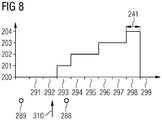
- Fig. 8 illustrates aspects related to discrete-time optimization. Illustrated in particular Fig. 8 different states 200-204 into which 291-299 can be classified for the different time intervals. The example corresponds to the Fig. 8 basically the example of Fig. 6 . However, in the example the Fig. 8 there is another state 204, where state 204 can be referred to as (iv) regeneration. During regeneration, the boundary condition 250 can be selected such that the power reserve 251 is restored in the corresponding time interval 298 before the power exchange 121 is reactivated (the power exchange 121 is reactivated in FIG Fig. 8 not shown).
- time period 241 of the time intervals 298 to be used to restore the power reserve 251 following the time intervals 296-297 with state 203 are provided, for example independence from agreements between the operators of the microcurrent network 100 and the main power network 120.
- an excessive depletion of the power reserve 251 can be avoided.
- Another strategy for avoiding excessive reduction of the power reserve 251 can also be achieved by taking into account a positive and / or negative tolerance 260 in connection with the power exchange 121 (cf. Fig. 7 where the corresponding tolerances in the time intervals 296, 297 in connection with the reduction of the power reserve 251 are illustrated).
- These tolerances 260 can relate, for example, to a predetermined value for the power exchange 121.
- the power exchange 121 between the microcurrent network 100 and the main power network 120 can be taken into account by taking into account various states 200-204.
- the target function and / or the boundary condition of the optimization can be adapted accordingly.
- An exemplary concrete implementation of such an adaptation of the boundary condition of the optimization is described below, the optimization being carried out as an integer linear optimization.
- the objective function of the optimization can take account of corresponding sales or operating parameters that can be achieved by using the power exchange 121.
- the target function can differentiate, for example, whether there is a concrete activation of the power exchange 121 by means of a corresponding control signal 310 or time intervals 296, 297 with state 203, or the basic possibility of the power exchange 121 in a standby state 201.
- the Objective function that affect the service exchange 121 it would also be possible to take into account further or different variables.
- the inequalities (1) - (7) of the boundary conditions of the optimization in state 203 can thus model the control of the micro-network 100 when the power exchange 121 is specifically activated.
- These boundary conditions can be integrated in other optimizations, for example in techniques as described in " Optimal operational planning for PV-Wind-Diesel-Battery Microgrid, GG Moshi, C. Bovo, and A. Berizzi, IEEE Eindhoven PowerTech, 2015 "are described.
- control signal 310 is received in connection with re-performing optimization at time 288).
- Typical contracts for control reserve power can then be used to specify how quickly the microcurrent network 100 must be ready to activate the power exchange 121, ie how quickly a subscriber must be ready to actually deliver or take up power to the main power network 120 after the control signal 310 has been received.
- a corresponding predetermined period of time 240 (compare Fig. 6 ) can be taken into account as a predetermined time period for the time intervals 294, 295 in state 202 within the framework of the boundary condition.
- a backup concept can be implemented.
- the micro-network 100 builds up a power reserve 251 at time intervals 293-298 with standby state 201 (ie basic offering of the power exchange 121) (cf. Fig. 5 ). This can prepare for the actual activation of the power exchange 121.
- a power reserve 251 for the time intervals 293-298 in state 201 can be integrated in particular into existing power reserve concepts by conventional optimizations. Components that provide energy, such as a battery or a running diesel generator, can make a positive contribution to the power reserve 251; while power delivered to consumers, for example, may require a certain amount of negative power reserve 251.
- a certain amount of energy can also be taken into account for the power exchange 121. In this way it can be ensured that the micro network 100 can react if the power exchange is specifically activated by means of the control signal 310.
- the boundary condition used in the optimization can, for example, have the following form, with OR req ( K ) or OR del ( K ) the power reserve required or made available of a 101-106 K node. How this is designed differs depending on the type of component: ⁇ Knot K , deliver the OR OR del K t n - ⁇ Knot K , need the OR OR req K t n ⁇ 0
- Efficiency increase the willingness to deliver or take up control power at the main network connection enables the operators of micro networks to increase the efficiency in the operation of the micro network.
- the main power grid can be stabilized. Power peaks can be cushioned. Cooperation between the operational planning of the main electricity network and the micro network is possible.
- the techniques described here supplement programs for the operational planning of microgrids, which are based in particular on integer linear optimizations.
- the techniques described here are well suited for complex, but runtime-critical applications with planning optimization at runtime.
- the integration of the service exchange can be particularly simple and without increased complexity by taking into account the expansion of conventional boundary conditions and / or target functions.
Landscapes
- Engineering & Computer Science (AREA)
- General Physics & Mathematics (AREA)
- Theoretical Computer Science (AREA)
- Business, Economics & Management (AREA)
- Physics & Mathematics (AREA)
- Strategic Management (AREA)
- Human Resources & Organizations (AREA)
- Economics (AREA)
- Power Engineering (AREA)
- Game Theory and Decision Science (AREA)
- Marketing (AREA)
- Software Systems (AREA)
- Development Economics (AREA)
- Medical Informatics (AREA)
- Evolutionary Computation (AREA)
- Computer Vision & Pattern Recognition (AREA)
- Artificial Intelligence (AREA)
- Entrepreneurship & Innovation (AREA)
- Automation & Control Theory (AREA)
- Operations Research (AREA)
- Quality & Reliability (AREA)
- Tourism & Hospitality (AREA)
- General Business, Economics & Management (AREA)
- Health & Medical Sciences (AREA)
- General Engineering & Computer Science (AREA)
- Supply And Distribution Of Alternating Current (AREA)
- Control Of Eletrric Generators (AREA)
- Feedback Control In General (AREA)
Priority Applications (3)
| Application Number | Priority Date | Filing Date | Title |
|---|---|---|---|
| EP18209863.2A EP3664242B1 (fr) | 2018-12-03 | 2018-12-03 | Planification de fonctionnement prédictive dans un micro-réseau à échange de performance entre le micro-réseau et un réseau électrique principal |
| ES18209863T ES2931500T3 (es) | 2018-12-03 | 2018-12-03 | Planificación operativa predictiva en una microrred con intercambio de potencia entre la microrred y una red eléctrica principal |
| US16/698,069 US11334033B2 (en) | 2018-12-03 | 2019-11-27 | Predictive operational planning in a microgrid with power exchange between the microgrid and a primary grid |
Applications Claiming Priority (1)
| Application Number | Priority Date | Filing Date | Title |
|---|---|---|---|
| EP18209863.2A EP3664242B1 (fr) | 2018-12-03 | 2018-12-03 | Planification de fonctionnement prédictive dans un micro-réseau à échange de performance entre le micro-réseau et un réseau électrique principal |
Publications (2)
| Publication Number | Publication Date |
|---|---|
| EP3664242A1 true EP3664242A1 (fr) | 2020-06-10 |
| EP3664242B1 EP3664242B1 (fr) | 2022-10-26 |
Family
ID=64572231
Family Applications (1)
| Application Number | Title | Priority Date | Filing Date |
|---|---|---|---|
| EP18209863.2A Not-in-force EP3664242B1 (fr) | 2018-12-03 | 2018-12-03 | Planification de fonctionnement prédictive dans un micro-réseau à échange de performance entre le micro-réseau et un réseau électrique principal |
Country Status (3)
| Country | Link |
|---|---|
| US (1) | US11334033B2 (fr) |
| EP (1) | EP3664242B1 (fr) |
| ES (1) | ES2931500T3 (fr) |
Families Citing this family (2)
| Publication number | Priority date | Publication date | Assignee | Title |
|---|---|---|---|---|
| EP3664243B1 (fr) * | 2018-12-04 | 2022-04-13 | Siemens Aktiengesellschaft | Planification de fonctionnement prédictive dans un micro-réseau en fonction des fenêtres temporelles de charge élevé d'un réseau électrique principal |
| CN116522584B (zh) * | 2023-03-07 | 2023-10-27 | 北京智中能源科技发展有限公司 | 一种配电网供电爬坡能力最大化计算的优化方法 |
Citations (3)
| Publication number | Priority date | Publication date | Assignee | Title |
|---|---|---|---|---|
| US20150039145A1 (en) * | 2013-07-31 | 2015-02-05 | Abb Technology Ag | Microgrid Energy Management System and Method for Controlling Operation of a Microgrid |
| DE102015206510A1 (de) * | 2015-04-13 | 2016-10-13 | Siemens Aktiengesellschaft | Koordination eines Leistungsaustauschs zwischen einem Verbraucher und einem Versorgungsnetz unter Verwendung von Energiebedarfs-/Energieerzeugungsprognosen |
| US20180173171A1 (en) * | 2015-06-12 | 2018-06-21 | United Technologies Corporation | Microgrid system and controller |
Family Cites Families (18)
| Publication number | Priority date | Publication date | Assignee | Title |
|---|---|---|---|---|
| DE10044169A1 (de) | 2000-09-07 | 2002-03-21 | Daimler Chrysler Ag | Verfahren zur zerstörungsfreien Wandstärkenprüfung |
| DE10331419A1 (de) | 2002-07-12 | 2004-01-22 | Mycrona Gesellschaft für innovative Messtechnik mbH | Verfahren und Vorrichtung zur Bestimmung der Ist-Position einer Struktur eines Untersuchungsobjektes |
| US20060288756A1 (en) | 2003-02-21 | 2006-12-28 | De Meurechy Guido D K | Method and apparatus for scanning corrosion and surface defects |
| EP1559500B1 (fr) | 2004-01-29 | 2011-08-17 | Siemens Aktiengesellschaft | Procédé et dispositif d'usinage mécanique d'un composant creux |
| DE102005042270B4 (de) | 2005-09-06 | 2015-11-19 | MTU Aero Engines AG | Verfahren zum Fertigen von Bohrungen und Fertigungsanordnung hierfür |
| DE102006022104B4 (de) | 2006-05-11 | 2012-09-06 | Fraunhofer-Gesellschaft zur Förderung der angewandten Forschung e.V. | Vorrichtung zur dreidimensionalen Vermessung eines Festkörpers |
| DE102007021809A1 (de) | 2007-04-20 | 2008-10-23 | Werth Messtechnik Gmbh | Verfahren und Vorrichtung zum dimensionellen Messen mit Koordinatenmessgeräten |
| DE102008016026A1 (de) | 2008-03-28 | 2009-10-01 | Mtu Aero Engines Gmbh | Verfahren und Vorrichtung zum Vermessen wenigstens einer Bohrung in zumindest einer ersten Oberfläche eines Bauteils |
| DE102008020948A1 (de) | 2008-04-25 | 2009-11-26 | Fraunhofer-Gesellschaft zur Förderung der angewandten Forschung e.V. | Röntgencomputertomograph und Verfahren zur Untersuchung eines Bauteils mittels Röntgencomputertomographie |
| DE102008048963B4 (de) | 2008-09-25 | 2011-08-25 | Technische Universität Braunschweig Carolo-Wilhelmina, 38106 | 3D-Geometrie-Erfassungsverfahren und -vorrichtung |
| DE102011056421A1 (de) | 2011-12-14 | 2013-06-20 | V&M Deutschland Gmbh | Verfahren zur Überwachung des Fertigungsprozesses von warmgefertigten Rohren aus Stahl |
| US9563215B2 (en) * | 2012-07-14 | 2017-02-07 | Causam Energy, Inc. | Method and apparatus for actively managing electric power supply for an electric power grid |
| DE102013104490A1 (de) | 2013-01-25 | 2014-07-31 | Werth Messtechnik Gmbh | Verfahren und Vorrichtung zur Bestimmung der Geometrie von Strukturen mittels Computertomografie |
| DE102014202021A1 (de) | 2014-02-05 | 2015-08-06 | Mahle International Gmbh | Verfahren zur Messung einer Wandstärke bei Hohlventilen |
| DE102014205420A1 (de) | 2014-03-24 | 2015-09-24 | Siemens Aktiengesellschaft | Verfahren und System zur Bestimmung der Wanddicke eines Bauteils |
| US10444806B2 (en) * | 2015-09-24 | 2019-10-15 | Causam Energy, Inc. | Systems and methods for aggregation and integration of distributed grid elements inputs for providing an interactive electric power grid geographic visualization |
| DE102016200779A1 (de) | 2016-01-21 | 2017-07-27 | MTU Aero Engines AG | Untersuchungsverfahren für ein zu wartendes hohles Bauteil einer Strömungsmaschine |
| CN106532715B (zh) * | 2016-12-30 | 2019-04-09 | 东南大学 | 一种基于非线性状态观测器的微电网分散式电压控制方法 |
-
2018
- 2018-12-03 EP EP18209863.2A patent/EP3664242B1/fr not_active Not-in-force
- 2018-12-03 ES ES18209863T patent/ES2931500T3/es active Active
-
2019
- 2019-11-27 US US16/698,069 patent/US11334033B2/en active Active
Patent Citations (3)
| Publication number | Priority date | Publication date | Assignee | Title |
|---|---|---|---|---|
| US20150039145A1 (en) * | 2013-07-31 | 2015-02-05 | Abb Technology Ag | Microgrid Energy Management System and Method for Controlling Operation of a Microgrid |
| DE102015206510A1 (de) * | 2015-04-13 | 2016-10-13 | Siemens Aktiengesellschaft | Koordination eines Leistungsaustauschs zwischen einem Verbraucher und einem Versorgungsnetz unter Verwendung von Energiebedarfs-/Energieerzeugungsprognosen |
| US20180173171A1 (en) * | 2015-06-12 | 2018-06-21 | United Technologies Corporation | Microgrid system and controller |
Non-Patent Citations (4)
| Title |
|---|
| BASIR KHAN M REYASUDIN ET AL: "Multi-agent based distributed control architecture for microgrid energy management and optimization", ENERGY CONVERSION AND MANAGEMENT, ELSEVIER SCIENCE PUBLISHERS, OXFORD, GB, vol. 112, 25 January 2016 (2016-01-25), pages 288 - 307, XP029406786, ISSN: 0196-8904, DOI: 10.1016/J.ENCONMAN.2016.01.011 * |
| G. G. MOSHI; C. BOVO; A. BERIZZI: "Optimal Operational Planning for PV-Wind-Diesel-Battery Microgrid", IEEE EINDHOVEN POWERTECH, 2015 |
| MOSHI GODFREY GLADSON ET AL: "Optimal operational planning for PV-Wind-Diesel-battery microgrid", 2015 IEEE EINDHOVEN POWERTECH, IEEE, 29 June 2015 (2015-06-29), pages 1 - 6, XP033215532, DOI: 10.1109/PTC.2015.7232461 * |
| R. MORENO; R. MOREIRA; G. STRBAC: "A MILP model for optimising multi-service portfolios of distributed energy storage", APPLIED ENERGY, vol. 137, 2015, pages 554 - 566, XP029098546, DOI: doi:10.1016/j.apenergy.2014.08.080 |
Also Published As
| Publication number | Publication date |
|---|---|
| US20200174429A1 (en) | 2020-06-04 |
| ES2931500T3 (es) | 2022-12-30 |
| EP3664242B1 (fr) | 2022-10-26 |
| US11334033B2 (en) | 2022-05-17 |
Similar Documents
| Publication | Publication Date | Title |
|---|---|---|
| EP3707798B1 (fr) | Methode pour controler le transfert de puissance electrique et reseau electrique | |
| DE102016214332B4 (de) | Aggregierte und optimierte virtuelles-kraftwerk-steuerung | |
| WO2012149965A1 (fr) | Procédé et dispositif de fourniture d'énergie électrique | |
| DE102014206381A1 (de) | Ladesystem für Elektro-Fahrzeuge | |
| EP2726317A1 (fr) | Fourniture d'énergie électrique | |
| DE102010006527A1 (de) | Anpassen von Lastprofilen und/oder Einspeiseprofilen | |
| DE102018202755A1 (de) | Verfahren und Steuervorrichtung zum Anpassen eines elektrischen Leistungsangebots an einen elektrischen Leistungsbedarf in einem elektrischen Netzwerk | |
| EP3063713A1 (fr) | Optimisation de la distribution de l'énergie électrique | |
| EP4070426A1 (fr) | Procédé d'exploitation de centre de données dans un réseau électrique et centre de données pour la mise en oeuvre d'un tel procédé | |
| WO2024022696A1 (fr) | Charge d'un véhicule électrique à un point de charge d'une maison | |
| DE102009035853A1 (de) | Verfahren zum Betreiben von elektrischen und/oder elektromechanischen Systemen | |
| EP3664242B1 (fr) | Planification de fonctionnement prédictive dans un micro-réseau à échange de performance entre le micro-réseau et un réseau électrique principal | |
| WO2021037553A1 (fr) | Procédé de stabilisation d'une grille d'énergie électrique | |
| EP3382841B1 (fr) | Utilisation hybride d'accumulateurs d'énergie | |
| WO2014048463A1 (fr) | Dispositif équipé d'une batterie tampon stationnaire pour le chargement d'un accumulateur d'énergie électrique et procédé | |
| EP3759785A1 (fr) | Procédé de régulation en temps réel d'un système d'alimentation et de distribution d'énergie | |
| EP3664243B1 (fr) | Planification de fonctionnement prédictive dans un micro-réseau en fonction des fenêtres temporelles de charge élevé d'un réseau électrique principal | |
| EP3042433B1 (fr) | Procédé et dispositif permettant la gestion optimale pour un système d'accumulation d'un système photovoltaïque | |
| DE102019121990A1 (de) | Verfahren zur Modellierung einer oder mehrerer Energiewandlungsanlagen in einem Energiemanagementsystem | |
| WO2020200588A1 (fr) | Procédé de gestion d'énergie assisté par ordinateur et système de gestion d'énergie | |
| DE102023002489A1 (de) | Wetterdatenbasiertes prädiktives Management einer Elektrofahrzeug-Ladeanlage | |
| WO2023247246A1 (fr) | Procédé et dispositif de détermination d'une séquence de récupération de réserves de fonctionnement à partir d'une pluralité d'installations pour fournir une réserve de fonctionnement totale | |
| EP3072202B1 (fr) | Procédé et dispositif permettant la gestion à rendement contrôlé d'un système d'accumulation pour un système photovoltaïque | |
| DE102024139556B3 (de) | Fahrzeugsystem zum verbessern von zeitschätzungen zum laden einer batterie in einem fahrzeug | |
| EP3560056B1 (fr) | Mémoire centrale et technique de commande à gestion d'énergie |
Legal Events
| Date | Code | Title | Description |
|---|---|---|---|
| PUAI | Public reference made under article 153(3) epc to a published international application that has entered the european phase |
Free format text: ORIGINAL CODE: 0009012 |
|
| STAA | Information on the status of an ep patent application or granted ep patent |
Free format text: STATUS: THE APPLICATION HAS BEEN PUBLISHED |
|
| AK | Designated contracting states |
Kind code of ref document: A1 Designated state(s): AL AT BE BG CH CY CZ DE DK EE ES FI FR GB GR HR HU IE IS IT LI LT LU LV MC MK MT NL NO PL PT RO RS SE SI SK SM TR |
|
| AX | Request for extension of the european patent |
Extension state: BA ME |
|
| STAA | Information on the status of an ep patent application or granted ep patent |
Free format text: STATUS: REQUEST FOR EXAMINATION WAS MADE |
|
| 17P | Request for examination filed |
Effective date: 20200619 |
|
| RBV | Designated contracting states (corrected) |
Designated state(s): AL AT BE BG CH CY CZ DE DK EE ES FI FR GB GR HR HU IE IS IT LI LT LU LV MC MK MT NL NO PL PT RO RS SE SI SK SM TR |
|
| STAA | Information on the status of an ep patent application or granted ep patent |
Free format text: STATUS: EXAMINATION IS IN PROGRESS |
|
| 17Q | First examination report despatched |
Effective date: 20210618 |
|
| GRAP | Despatch of communication of intention to grant a patent |
Free format text: ORIGINAL CODE: EPIDOSNIGR1 |
|
| STAA | Information on the status of an ep patent application or granted ep patent |
Free format text: STATUS: GRANT OF PATENT IS INTENDED |
|
| INTG | Intention to grant announced |
Effective date: 20220516 |
|
| GRAS | Grant fee paid |
Free format text: ORIGINAL CODE: EPIDOSNIGR3 |
|
| GRAA | (expected) grant |
Free format text: ORIGINAL CODE: 0009210 |
|
| STAA | Information on the status of an ep patent application or granted ep patent |
Free format text: STATUS: THE PATENT HAS BEEN GRANTED |
|
| AK | Designated contracting states |
Kind code of ref document: B1 Designated state(s): AL AT BE BG CH CY CZ DE DK EE ES FI FR GB GR HR HU IE IS IT LI LT LU LV MC MK MT NL NO PL PT RO RS SE SI SK SM TR |
|
| REG | Reference to a national code |
Ref country code: GB Ref legal event code: FG4D Free format text: NOT ENGLISH |
|
| REG | Reference to a national code |
Ref country code: CH Ref legal event code: EP |
|
| REG | Reference to a national code |
Ref country code: DE Ref legal event code: R096 Ref document number: 502018010907 Country of ref document: DE |
|
| REG | Reference to a national code |
Ref country code: AT Ref legal event code: REF Ref document number: 1527767 Country of ref document: AT Kind code of ref document: T Effective date: 20221115 |
|
| REG | Reference to a national code |
Ref country code: IE Ref legal event code: FG4D Free format text: LANGUAGE OF EP DOCUMENT: GERMAN |
|
| REG | Reference to a national code |
Ref country code: ES Ref legal event code: FG2A Ref document number: 2931500 Country of ref document: ES Kind code of ref document: T3 Effective date: 20221230 |
|
| REG | Reference to a national code |
Ref country code: LT Ref legal event code: MG9D |
|
| REG | Reference to a national code |
Ref country code: NL Ref legal event code: MP Effective date: 20221026 |
|
| PG25 | Lapsed in a contracting state [announced via postgrant information from national office to epo] |
Ref country code: NL Free format text: LAPSE BECAUSE OF FAILURE TO SUBMIT A TRANSLATION OF THE DESCRIPTION OR TO PAY THE FEE WITHIN THE PRESCRIBED TIME-LIMIT Effective date: 20221026 |
|
| PG25 | Lapsed in a contracting state [announced via postgrant information from national office to epo] |
Ref country code: SE Free format text: LAPSE BECAUSE OF FAILURE TO SUBMIT A TRANSLATION OF THE DESCRIPTION OR TO PAY THE FEE WITHIN THE PRESCRIBED TIME-LIMIT Effective date: 20221026 Ref country code: PT Free format text: LAPSE BECAUSE OF FAILURE TO SUBMIT A TRANSLATION OF THE DESCRIPTION OR TO PAY THE FEE WITHIN THE PRESCRIBED TIME-LIMIT Effective date: 20230227 Ref country code: NO Free format text: LAPSE BECAUSE OF FAILURE TO SUBMIT A TRANSLATION OF THE DESCRIPTION OR TO PAY THE FEE WITHIN THE PRESCRIBED TIME-LIMIT Effective date: 20230126 Ref country code: LT Free format text: LAPSE BECAUSE OF FAILURE TO SUBMIT A TRANSLATION OF THE DESCRIPTION OR TO PAY THE FEE WITHIN THE PRESCRIBED TIME-LIMIT Effective date: 20221026 Ref country code: FI Free format text: LAPSE BECAUSE OF FAILURE TO SUBMIT A TRANSLATION OF THE DESCRIPTION OR TO PAY THE FEE WITHIN THE PRESCRIBED TIME-LIMIT Effective date: 20221026 |
|
| PGFP | Annual fee paid to national office [announced via postgrant information from national office to epo] |
Ref country code: ES Payment date: 20230327 Year of fee payment: 5 |
|
| PG25 | Lapsed in a contracting state [announced via postgrant information from national office to epo] |
Ref country code: RS Free format text: LAPSE BECAUSE OF FAILURE TO SUBMIT A TRANSLATION OF THE DESCRIPTION OR TO PAY THE FEE WITHIN THE PRESCRIBED TIME-LIMIT Effective date: 20221026 Ref country code: PL Free format text: LAPSE BECAUSE OF FAILURE TO SUBMIT A TRANSLATION OF THE DESCRIPTION OR TO PAY THE FEE WITHIN THE PRESCRIBED TIME-LIMIT Effective date: 20221026 Ref country code: LV Free format text: LAPSE BECAUSE OF FAILURE TO SUBMIT A TRANSLATION OF THE DESCRIPTION OR TO PAY THE FEE WITHIN THE PRESCRIBED TIME-LIMIT Effective date: 20221026 Ref country code: IS Free format text: LAPSE BECAUSE OF FAILURE TO SUBMIT A TRANSLATION OF THE DESCRIPTION OR TO PAY THE FEE WITHIN THE PRESCRIBED TIME-LIMIT Effective date: 20230226 Ref country code: HR Free format text: LAPSE BECAUSE OF FAILURE TO SUBMIT A TRANSLATION OF THE DESCRIPTION OR TO PAY THE FEE WITHIN THE PRESCRIBED TIME-LIMIT Effective date: 20221026 Ref country code: GR Free format text: LAPSE BECAUSE OF FAILURE TO SUBMIT A TRANSLATION OF THE DESCRIPTION OR TO PAY THE FEE WITHIN THE PRESCRIBED TIME-LIMIT Effective date: 20230127 |
|
| PGFP | Annual fee paid to national office [announced via postgrant information from national office to epo] |
Ref country code: IT Payment date: 20221227 Year of fee payment: 5 Ref country code: GB Payment date: 20230103 Year of fee payment: 5 Ref country code: DE Payment date: 20230217 Year of fee payment: 5 |
|
| REG | Reference to a national code |
Ref country code: DE Ref legal event code: R097 Ref document number: 502018010907 Country of ref document: DE |
|
| PG25 | Lapsed in a contracting state [announced via postgrant information from national office to epo] |
Ref country code: SM Free format text: LAPSE BECAUSE OF FAILURE TO SUBMIT A TRANSLATION OF THE DESCRIPTION OR TO PAY THE FEE WITHIN THE PRESCRIBED TIME-LIMIT Effective date: 20221026 Ref country code: RO Free format text: LAPSE BECAUSE OF FAILURE TO SUBMIT A TRANSLATION OF THE DESCRIPTION OR TO PAY THE FEE WITHIN THE PRESCRIBED TIME-LIMIT Effective date: 20221026 Ref country code: EE Free format text: LAPSE BECAUSE OF FAILURE TO SUBMIT A TRANSLATION OF THE DESCRIPTION OR TO PAY THE FEE WITHIN THE PRESCRIBED TIME-LIMIT Effective date: 20221026 Ref country code: DK Free format text: LAPSE BECAUSE OF FAILURE TO SUBMIT A TRANSLATION OF THE DESCRIPTION OR TO PAY THE FEE WITHIN THE PRESCRIBED TIME-LIMIT Effective date: 20221026 Ref country code: CZ Free format text: LAPSE BECAUSE OF FAILURE TO SUBMIT A TRANSLATION OF THE DESCRIPTION OR TO PAY THE FEE WITHIN THE PRESCRIBED TIME-LIMIT Effective date: 20221026 |
|
| REG | Reference to a national code |
Ref country code: CH Ref legal event code: PL |
|
| REG | Reference to a national code |
Ref country code: BE Ref legal event code: MM Effective date: 20221231 |
|
| PG25 | Lapsed in a contracting state [announced via postgrant information from national office to epo] |
Ref country code: SK Free format text: LAPSE BECAUSE OF FAILURE TO SUBMIT A TRANSLATION OF THE DESCRIPTION OR TO PAY THE FEE WITHIN THE PRESCRIBED TIME-LIMIT Effective date: 20221026 Ref country code: LU Free format text: LAPSE BECAUSE OF NON-PAYMENT OF DUE FEES Effective date: 20221203 Ref country code: AL Free format text: LAPSE BECAUSE OF FAILURE TO SUBMIT A TRANSLATION OF THE DESCRIPTION OR TO PAY THE FEE WITHIN THE PRESCRIBED TIME-LIMIT Effective date: 20221026 |
|
| PLBE | No opposition filed within time limit |
Free format text: ORIGINAL CODE: 0009261 |
|
| STAA | Information on the status of an ep patent application or granted ep patent |
Free format text: STATUS: NO OPPOSITION FILED WITHIN TIME LIMIT |
|
| 26N | No opposition filed |
Effective date: 20230727 |
|
| PG25 | Lapsed in a contracting state [announced via postgrant information from national office to epo] |
Ref country code: LI Free format text: LAPSE BECAUSE OF NON-PAYMENT OF DUE FEES Effective date: 20221231 Ref country code: IE Free format text: LAPSE BECAUSE OF NON-PAYMENT OF DUE FEES Effective date: 20221203 Ref country code: CH Free format text: LAPSE BECAUSE OF NON-PAYMENT OF DUE FEES Effective date: 20221231 |
|
| PG25 | Lapsed in a contracting state [announced via postgrant information from national office to epo] |
Ref country code: SI Free format text: LAPSE BECAUSE OF FAILURE TO SUBMIT A TRANSLATION OF THE DESCRIPTION OR TO PAY THE FEE WITHIN THE PRESCRIBED TIME-LIMIT Effective date: 20221026 Ref country code: FR Free format text: LAPSE BECAUSE OF NON-PAYMENT OF DUE FEES Effective date: 20221226 Ref country code: BE Free format text: LAPSE BECAUSE OF NON-PAYMENT OF DUE FEES Effective date: 20221231 |
|
| PG25 | Lapsed in a contracting state [announced via postgrant information from national office to epo] |
Ref country code: HU Free format text: LAPSE BECAUSE OF FAILURE TO SUBMIT A TRANSLATION OF THE DESCRIPTION OR TO PAY THE FEE WITHIN THE PRESCRIBED TIME-LIMIT; INVALID AB INITIO Effective date: 20181203 |
|
| PG25 | Lapsed in a contracting state [announced via postgrant information from national office to epo] |
Ref country code: CY Free format text: LAPSE BECAUSE OF FAILURE TO SUBMIT A TRANSLATION OF THE DESCRIPTION OR TO PAY THE FEE WITHIN THE PRESCRIBED TIME-LIMIT Effective date: 20221026 |
|
| PG25 | Lapsed in a contracting state [announced via postgrant information from national office to epo] |
Ref country code: MK Free format text: LAPSE BECAUSE OF FAILURE TO SUBMIT A TRANSLATION OF THE DESCRIPTION OR TO PAY THE FEE WITHIN THE PRESCRIBED TIME-LIMIT Effective date: 20221026 |
|
| PG25 | Lapsed in a contracting state [announced via postgrant information from national office to epo] |
Ref country code: MC Free format text: LAPSE BECAUSE OF FAILURE TO SUBMIT A TRANSLATION OF THE DESCRIPTION OR TO PAY THE FEE WITHIN THE PRESCRIBED TIME-LIMIT Effective date: 20221026 |
|
| PG25 | Lapsed in a contracting state [announced via postgrant information from national office to epo] |
Ref country code: MC Free format text: LAPSE BECAUSE OF FAILURE TO SUBMIT A TRANSLATION OF THE DESCRIPTION OR TO PAY THE FEE WITHIN THE PRESCRIBED TIME-LIMIT Effective date: 20221026 |
|
| REG | Reference to a national code |
Ref country code: DE Ref legal event code: R119 Ref document number: 502018010907 Country of ref document: DE |
|
| PG25 | Lapsed in a contracting state [announced via postgrant information from national office to epo] |
Ref country code: BG Free format text: LAPSE BECAUSE OF FAILURE TO SUBMIT A TRANSLATION OF THE DESCRIPTION OR TO PAY THE FEE WITHIN THE PRESCRIBED TIME-LIMIT Effective date: 20221026 |
|
| GBPC | Gb: european patent ceased through non-payment of renewal fee |
Effective date: 20231203 |
|
| PG25 | Lapsed in a contracting state [announced via postgrant information from national office to epo] |
Ref country code: MT Free format text: LAPSE BECAUSE OF FAILURE TO SUBMIT A TRANSLATION OF THE DESCRIPTION OR TO PAY THE FEE WITHIN THE PRESCRIBED TIME-LIMIT Effective date: 20221026 |
|
| PG25 | Lapsed in a contracting state [announced via postgrant information from national office to epo] |
Ref country code: DE Free format text: LAPSE BECAUSE OF NON-PAYMENT OF DUE FEES Effective date: 20240702 |
|
| PG25 | Lapsed in a contracting state [announced via postgrant information from national office to epo] |
Ref country code: GB Free format text: LAPSE BECAUSE OF NON-PAYMENT OF DUE FEES Effective date: 20231203 |
|
| PG25 | Lapsed in a contracting state [announced via postgrant information from national office to epo] |
Ref country code: GB Free format text: LAPSE BECAUSE OF NON-PAYMENT OF DUE FEES Effective date: 20231203 Ref country code: DE Free format text: LAPSE BECAUSE OF NON-PAYMENT OF DUE FEES Effective date: 20240702 |
|
| REG | Reference to a national code |
Ref country code: ES Ref legal event code: FD2A Effective date: 20250124 |
|
| REG | Reference to a national code |
Ref country code: AT Ref legal event code: MM01 Ref document number: 1527767 Country of ref document: AT Kind code of ref document: T Effective date: 20231203 |
|
| PG25 | Lapsed in a contracting state [announced via postgrant information from national office to epo] |
Ref country code: ES Free format text: LAPSE BECAUSE OF NON-PAYMENT OF DUE FEES Effective date: 20231204 |
|
| PG25 | Lapsed in a contracting state [announced via postgrant information from national office to epo] |
Ref country code: AT Free format text: LAPSE BECAUSE OF NON-PAYMENT OF DUE FEES Effective date: 20231203 |
|
| PG25 | Lapsed in a contracting state [announced via postgrant information from national office to epo] |
Ref country code: IT Free format text: LAPSE BECAUSE OF NON-PAYMENT OF DUE FEES Effective date: 20231203 |
|
| PG25 | Lapsed in a contracting state [announced via postgrant information from national office to epo] |
Ref country code: TR Free format text: LAPSE BECAUSE OF FAILURE TO SUBMIT A TRANSLATION OF THE DESCRIPTION OR TO PAY THE FEE WITHIN THE PRESCRIBED TIME-LIMIT Effective date: 20221026 |
|
| PGFP | Annual fee paid to national office [announced via postgrant information from national office to epo] |
Ref country code: AT Payment date: 20260410 Year of fee payment: 5 |