EP3664263A1 - Vorrichtung zum halten eines rotorkerns sowie vorrichtung und verfahren zur herstellung eines magneteingebetteten kerns - Google Patents
Vorrichtung zum halten eines rotorkerns sowie vorrichtung und verfahren zur herstellung eines magneteingebetteten kerns Download PDFInfo
- Publication number
- EP3664263A1 EP3664263A1 EP18899035.2A EP18899035A EP3664263A1 EP 3664263 A1 EP3664263 A1 EP 3664263A1 EP 18899035 A EP18899035 A EP 18899035A EP 3664263 A1 EP3664263 A1 EP 3664263A1
- Authority
- EP
- European Patent Office
- Prior art keywords
- plate
- rotor core
- resin
- magnet insertion
- insertion hole
- Prior art date
- Legal status (The legal status is an assumption and is not a legal conclusion. Google has not performed a legal analysis and makes no representation as to the accuracy of the status listed.)
- Granted
Links
Images



Classifications
-
- H—ELECTRICITY
- H02—GENERATION; CONVERSION OR DISTRIBUTION OF ELECTRIC POWER
- H02K—DYNAMO-ELECTRIC MACHINES
- H02K15/00—Processes or apparatus specially adapted for manufacturing, assembling, maintaining or repairing of dynamo-electric machines
-
- H—ELECTRICITY
- H02—GENERATION; CONVERSION OR DISTRIBUTION OF ELECTRIC POWER
- H02K—DYNAMO-ELECTRIC MACHINES
- H02K15/00—Processes or apparatus specially adapted for manufacturing, assembling, maintaining or repairing of dynamo-electric machines
- H02K15/02—Processes or apparatus specially adapted for manufacturing, assembling, maintaining or repairing of dynamo-electric machines of stator or rotor bodies
- H02K15/03—Processes or apparatus specially adapted for manufacturing, assembling, maintaining or repairing of dynamo-electric machines of stator or rotor bodies having permanent magnets
-
- B—PERFORMING OPERATIONS; TRANSPORTING
- B29—WORKING OF PLASTICS; WORKING OF SUBSTANCES IN A PLASTIC STATE IN GENERAL
- B29C—SHAPING OR JOINING OF PLASTICS; SHAPING OF MATERIAL IN A PLASTIC STATE, NOT OTHERWISE PROVIDED FOR; AFTER-TREATMENT OF THE SHAPED PRODUCTS, e.g. REPAIRING
- B29C45/00—Injection moulding, i.e. forcing the required volume of moulding material through a nozzle into a closed mould; Apparatus therefor
- B29C45/14—Injection moulding, i.e. forcing the required volume of moulding material through a nozzle into a closed mould; Apparatus therefor incorporating preformed parts or layers, e.g. injection moulding around inserts or for coating articles
- B29C45/14065—Positioning or centering articles in the mould
-
- H—ELECTRICITY
- H02—GENERATION; CONVERSION OR DISTRIBUTION OF ELECTRIC POWER
- H02K—DYNAMO-ELECTRIC MACHINES
- H02K1/00—Details of the magnetic circuit
- H02K1/06—Details of the magnetic circuit characterised by the shape, form or construction
- H02K1/22—Rotating parts of the magnetic circuit
- H02K1/28—Means for mounting or fastening rotating magnetic parts on to, or to, the rotor structures
-
- H—ELECTRICITY
- H02—GENERATION; CONVERSION OR DISTRIBUTION OF ELECTRIC POWER
- H02K—DYNAMO-ELECTRIC MACHINES
- H02K15/00—Processes or apparatus specially adapted for manufacturing, assembling, maintaining or repairing of dynamo-electric machines
- H02K15/02—Processes or apparatus specially adapted for manufacturing, assembling, maintaining or repairing of dynamo-electric machines of stator or rotor bodies
-
- H—ELECTRICITY
- H02—GENERATION; CONVERSION OR DISTRIBUTION OF ELECTRIC POWER
- H02K—DYNAMO-ELECTRIC MACHINES
- H02K15/00—Processes or apparatus specially adapted for manufacturing, assembling, maintaining or repairing of dynamo-electric machines
- H02K15/12—Impregnating, moulding insulation, heating or drying of windings, stators, rotors or machines
-
- B—PERFORMING OPERATIONS; TRANSPORTING
- B29—WORKING OF PLASTICS; WORKING OF SUBSTANCES IN A PLASTIC STATE IN GENERAL
- B29L—INDEXING SCHEME ASSOCIATED WITH SUBCLASS B29C, RELATING TO PARTICULAR ARTICLES
- B29L2031/00—Other particular articles
- B29L2031/748—Machines or parts thereof not otherwise provided for
- B29L2031/7498—Rotors
-
- H—ELECTRICITY
- H02—GENERATION; CONVERSION OR DISTRIBUTION OF ELECTRIC POWER
- H02K—DYNAMO-ELECTRIC MACHINES
- H02K1/00—Details of the magnetic circuit
- H02K1/06—Details of the magnetic circuit characterised by the shape, form or construction
- H02K1/22—Rotating parts of the magnetic circuit
- H02K1/27—Rotor cores with permanent magnets
- H02K1/2706—Inner rotors
- H02K1/272—Inner rotors the magnetisation axis of the magnets being perpendicular to the rotor axis
- H02K1/274—Inner rotors the magnetisation axis of the magnets being perpendicular to the rotor axis the rotor consisting of two or more circumferentially positioned magnets
- H02K1/2753—Inner rotors the magnetisation axis of the magnets being perpendicular to the rotor axis the rotor consisting of two or more circumferentially positioned magnets the rotor consisting of magnets or groups of magnets arranged with alternating polarity
- H02K1/276—Magnets embedded in the magnetic core, e.g. interior permanent magnets [IPM]
-
- Y—GENERAL TAGGING OF NEW TECHNOLOGICAL DEVELOPMENTS; GENERAL TAGGING OF CROSS-SECTIONAL TECHNOLOGIES SPANNING OVER SEVERAL SECTIONS OF THE IPC; TECHNICAL SUBJECTS COVERED BY FORMER USPC CROSS-REFERENCE ART COLLECTIONS [XRACs] AND DIGESTS
- Y10—TECHNICAL SUBJECTS COVERED BY FORMER USPC
- Y10T—TECHNICAL SUBJECTS COVERED BY FORMER US CLASSIFICATION
- Y10T29/00—Metal working
- Y10T29/53—Means to assemble or disassemble
- Y10T29/5313—Means to assemble electrical device
-
- Y—GENERAL TAGGING OF NEW TECHNOLOGICAL DEVELOPMENTS; GENERAL TAGGING OF CROSS-SECTIONAL TECHNOLOGIES SPANNING OVER SEVERAL SECTIONS OF THE IPC; TECHNICAL SUBJECTS COVERED BY FORMER USPC CROSS-REFERENCE ART COLLECTIONS [XRACs] AND DIGESTS
- Y10—TECHNICAL SUBJECTS COVERED BY FORMER USPC
- Y10T—TECHNICAL SUBJECTS COVERED BY FORMER US CLASSIFICATION
- Y10T29/00—Metal working
- Y10T29/53—Means to assemble or disassemble
- Y10T29/5313—Means to assemble electrical device
- Y10T29/53143—Motor or generator
Definitions
- the present invention relates to a rotor core retaining jig, a manufacturing device and a manufacturing method for a magnet embedded core.
- a magnet embedded core used in rotating electric machinery such as an electric motor
- a magnet embedded core including a rotor core provided with a magnet insertion hole forming a through hole defining openings on both ends in an axial direction, a magnet disposed in the magnet insertion hole, and resin filling the magnet insertion hole, such that the magnet is fixed to the rotor core by the resin.
- a manufacturing device for a magnet embedded core of this kind there is known a manufacturing device including an upper die and a lower die for pressurizing the rotor core in the axial direction, an intermediate die having a gate configured to communicate with one opening of the magnet insertion hole and arranged to be located between the upper die and the rotor core or between the lower die and the rotor core, wherein a resin pot is provided in the upper die or the lower die, such that in a state where the other opening of the magnet insertion hole is closed by the upper die, the lower die, or the like, molten resin in the resin pot is pressurized to fill the resin into the magnet insertion hole from the resin pot via the gate (for example, see Patent Documents 1 to 3).
- both the force pressing the upper die or the lower die against the end surface of the rotor core and the force pressing the rotor core against the intermediate die are determined by the pressurizing force by the upper die and the lower die, and thus, the pressing forces cannot be determined individually.
- the axial compressive force that acts on the rotor core may become unnecessarily large, so that deformation such as a warp may be caused in the rotor core to deteriorate the quality of the magnet embedded core.
- the present invention has been made in view of such prior art problems, and an object of the present invention is to prevent the axial compressive force that acts on the rotor core from becoming unnecessarily large and to enable a high-quality magnet embedded core to be manufactured efficiently.
- a rotor core retaining jig for manufacturing a magnet embedded core is a retaining jig for a rotor core including a magnet insertion hole forming a through hole defining openings on both end surfaces in an axial direction, comprising: a first plate configured to contact against one of the end surfaces of the rotor core and including a gate configured to communicate with the corresponding opening of the magnet insertion hole; a second plate configured to oppose another of the end surfaces of the rotor core; a closure member coupled to the second plate via a compression spring member and configured to be capable of closing the opening of the magnet insertion hole on the other of the end surfaces; and a coupling member that couples the first plate and the second plate to each other such that the closure member closes the opening and a spring force of the compression spring member becomes a prescribed value.
- the rotor core retaining jig of the aforementioned embodiment is used to retain a rotor core including multiple magnet insertion holes, and the closure member is divided into multiple closure members each corresponding to at least one of the magnet insertion holes, and the compression spring is provided for each closure member.
- the coupling member comprises a rod portion and a pair of flange portions provided on either end of the rod portion, and the first plate and the second plate include cutout portions each opening at an outer edge of the corresponding plate and defining a shoulder portion against which the corresponding flange portion contacts.
- a manufacturing device of a magnet embedded core is a manufacturing device for a magnet embedded core comprising a rotor core provided with a magnet insertion hole forming a through hole defining openings on end surfaces in an axial direction, a magnet disposed in the magnet insertion hole, and resin filling the magnet insertion hole, the manufacturing device comprising: the rotor core retaining jig according to the aforementioned embodiment; a first member contacting against the first plate of the rotor core retaining jig and provided with a resin pot configured to communicate with the gate; a second member opposing the first member via the rotor core retaining jig and relatively movable toward and away from the first member; a resin introducing device for introducing molten resin from the resin pot into the magnet insertion hole via the gate; and a pressing member located between the second member and the first plate to press the first plate against the first member by a pressurizing force transmitted from the second member to the first plate.
- the pressing member consists of a rod-like member having a base end fixed to the second member and a free end capable of contacting against the first plate.
- the pressing of the first plate by the pressing member can be performed easily and reliably.
- the pressing member consists of a rod-like member having a base end fixed to the first plate and a free end capable of contacting against the second member.
- the pressing of the first plate by the pressing member can be performed easily and reliably, and the first plate can be made compact.
- a manufacturing method of a magnet embedded core is a manufacturing method for a magnet embedded core comprising a rotor core provided with a magnet insertion hole forming a through hole defining openings on both end surfaces in an axial direction, a magnet disposed in the magnet insertion hole, and resin filling the magnet insertion hole, the manufacturing method comprising: a rotor core placing step of placing the rotor core on the first plate of the rotor core retaining jig according to the aforementioned embodiment such that the magnet insertion hole is aligned with the gate; a plate placing step of placing the second plate on the rotor core to close the opening of the magnet insertion hole with the closure member; a plate coupling step of coupling the first plate and the second plate to each other with the coupling member, with the rotor core being sandwiched by the first plate and the second plate; a jig placing step of placing the rotor core retaining jig on a first member provided with a resin pot such that the
- the manufacturing method for the magnet embedded core of the aforementioned embodiment preferably comprises, prior to the plate placing step, a resin inserting step of inserting solid resin into the resin pot, and the resin introducing step comprises a melting step of causing the solid resin inserted into the resin pot to melt in the resin pot and a pressurizing step of pressurizing the molten resin to introduce the molten resin into the magnet insertion hole.
- the magnet embedded core 1 is a component part of rotating machinery such as an electric motor, and includes a rotor core 2.
- the rotor core 2 consists of a laminated iron core formed by laminating a plurality of electromagnetic steel sheets and joining the electromagnetic steel sheets together by using a known joining method (such as crimping, laser welding, gluing, etc.).
- the rotor core 2 is substantially annular in shape in plan view, and is centrally provided with a shaft hole 3 extending therethrough in an axial direction.
- the rotor core 2 is formed with a plurality of magnet insertion holes 4 each defining a substantially rectangular space.
- the magnet insertion holes 4 extend through the rotor core 2 in the axial direction, and each open out at both of the end surfaces of the rotor core 2.
- the magnet insertion holes 4 are formed in four locations that are circumferentially arranged at a regular interval.
- the magnet insertion holes 4 are not limited to this embodiment, but can be arranged in any other different way with regard to shape, number and arrangement.
- a substantially rectangular parallelepiped shaped magnet 5 is received in each magnet insertion hole 4.
- Each magnet 5 may consist of, for example, a ferrite-based sintered magnet or a permanent magnet (with or without magnetization) such as a neodymium magnet.
- the dimensions of each magnet 5 are slightly smaller than the corresponding dimensions of the magnet insertion hole 4.
- This gap is filled with resin 6 which fixes the magnet 5 to the rotor core 2.
- the resin 6 may consist of thermosetting resin such as epoxy resin.
- the magnet 5 in each magnet insertion hole 4 is inwardly offset (or offset toward the center of the rotor core 2) so that the outer surface of the magnet 5 on the inner side thereof contacts against the inner surface of the magnet insertion hole 4 opposing it.
- the magnets 5 are uniformly arranged in regard to the radial positioning thereof. This, in cooperation with the magnet insertion holes 4 arranged at regular intervals in regard to the circumferential positioning thereof with respect to the rotor core 2, prevents the magnets 5 from causing any rotational imbalance of the rotor core 2.
- the magnets 5 may also be offset in the opposite radial direction from that shown in Figure 1 (or offset away from the center of the rotor core 2).
- the rotor core retaining jig 10 includes a lower first plate 12 and an upper second plate 14a that oppose each other.
- the first plate 12 is formed of a gate plate 16 and a cull plate 18 each consisting of a rectangular flat plate and overlapping each other.
- the gate plate 16 and the cull plate 18 may be detachably unified by bolts (not shown).
- the gate plate 16 has a top surface 16A configured to contact against a lower end surface 2A of the rotor core 2 and gates 20 configured to individually communicate with lower openings 4A of the respective magnet insertion holes 4.
- the cull plate 18 is disposed under the gate plate 16 and has cull openings 22 configured to communicate with the respective gates 20 and resin pots 80 of a later-described magnet embedded core manufacturing device 60.
- the second plate 14 is constituted of a rectangular flat plate, and opposes an upper end surface 2B of the rotor core 2.
- the second plate 14 supports closure members 26 for the respective magnet insertion holes 4 by associated bolts 24 in a suspended manner so as to be movable vertically.
- Each closure member 26 includes a bottom surface 26A having an area larger than that of the upper opening 4B of the magnet insertion hole 4 and capable of contacting against the upper end surface 2B of the rotor core 2.
- the lower limit position of each closure member 26 is determined by contacting of a head 24A of the associated bolt 24 against a shoulder-shaped bottom of an associated bolt through hole 14A formed in the second plate 14.
- a compression coil spring 28 is attached between the second plate 14 and each closure member 26.
- the compression coil spring 28 is individually provided for each closure member 26, and urges the closure member 26 toward the first plate 12.
- the closure members 26 and the compression coil springs 28 are provided for the respective magnet insertion holes 4. It is to be noted that, as shown in Figure 4 , each closure member 26 is supported by two bolts 24, and the compression coil springs 28 are provided such that two compression coil springs 28 are provided in parallel for each closure member 26.
- the first plate 12 is larger in size than the second plate 14, and includes a rectangular frame-shaped projecting portion 17 that projects outward from an outer edge of the second plate 14 in plan view.
- the first plate 12 and the second plate 14 are coupled to each other by coupling members 30 in four positions at front and rear on left and right sides in a state where the rotor core 2 is sandwiched between the first plate 12 and the closure members 26.
- Each coupling member 30 includes a rod portion 30A and a pair of flange portions 30B, 30C respectively provided at lower and upper ends of the rod portion 30A.
- the first plate 12 and the second plate 14 are formed with cutout portions 32, 34 each extending linearly in the left and right direction and opening at left or right outer edge of the associated plates 12, 14.
- the cutout portions 32, 34 are provided to be aligned vertically in four positions at front and rear on left and right sides, and as shown in enlarged partial perspective views (A) and (B) in Figure 3 , respectively include recessed grooves 32A, 34A which the flange portions 30B, 30C can engage, and slit-shaped openings 32B, 34B formed in the bottoms of the recessed grooves 32A, 34A such that the rod portion 30A can pass therethrough, and the flange portions 30B, 30C contact against shoulder portions 32C, 34C defined by parts of the recessed grooves 32A, 34A remaining on both sides of the openings 32B, 34B.
- each coupling member 30 couples the first plate 12 and the second plate 14 to each other such that a spring force of the compression coil spring 28 becomes a prescribed value.
- each closure member 26 is pressed against the upper end surface 2B of the rotor core 2 by the spring force of the compression coil spring 28 and closes the upper opening 4B of the corresponding magnet insertion hole 4.
- the flange portions 30B, 30C are entirely received in the recessed grooves 32A, 34A, and do not protrude below the first plate 12 and above the second plate 14.
- the rotor core 2 can be set in the rotor core retaining jig 10 by use of a core setting device 40 shown in Figure 5 .
- the core setting device 40 includes a flat plate-shaped base 42, a flat plate-shaped top member 46 disposed above the base 42 to oppose the same by multiple post members 44 extending upright from the base 42, a hydraulic pressurizing device (cylinder-piston device) 48 mounted on the bottom surface of the top member 46, and a flat plate-shaped pressurizing plate 52 mounted on a piston rod 50 of the pressurizing device 48.
- the first plate 12 is placed on the base 42, the magnets 5 are inserted into the respective magnet insertion holes 4, and then, the second plate 14 is placed on the rotor core 2 such that each closure member 26 is aligned with the associated magnet insertion hole 4.
- the pressurizing device 48 is driven to press the pressurizing plate 52 against the second plate 14 to thereby cause compressive deformation in each compression coil spring 28.
- the flange portions 30B, 30C of the coupling members 30 are inserted into the corresponding cutout portions 32, 34 from both left and right sides.
- the spring force of the compression coil spring 28 causes the flange portions 30B, 30C to be pressed against the shoulder portions 32C, 34C.
- the first plate 12 and the second plate 14 are coupled to each other by the coupling members 30, with the spring force of each compression coil spring 28 having the prescribed value.
- the rotor core 2 can be treated, together with the rotor core retaining jig 10, as a sub-assembly in that the opening 4B of each magnet insertion hole 4 is closed by the corresponding closure member 26 with a pressing force resulting from the spring force of the compression coil spring 28.
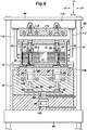
- the magnet embedded core manufacturing device 60 includes multiple post members 62 that extend vertically, a fixed platen 64 fixed to upper ends of the post members 62, and a movable platen 66 that is movable vertically and guided by the post members 62.
- the movable platen 66 is driven in the vertical direction by a drive device (not shown) using hydraulic pressure or the like, and can move toward and away from the fixed platen 64.
- a first member 70 is mounted on the movable platen 66.
- the first member 70 is constituted of an assembly in which a lower member 72, an intermediate member 74, and an upper member 76 are stacked.
- the upper member 76 is formed with multiple resin pots 80 corresponding to the respective magnet insertion holes 4 of the rotor core 2. Each resin pot 80 opens in the top surface of the upper member 76 to communicate with the corresponding cull opening 22.
- the intermediate member 74 is formed with plunger chambers 82 and push rod chambers 84 communicating with the associated resin pots 80.
- each plunger chamber 82 is provided with a plunger 86 to be vertically movable and each push rod chamber 84 is provided with a push rod 88 to be vertically movable.
- the resin pots 80, the plunger chambers 82, and the cull openings 22 are bores having the same inner diameter, and each plunger 86 can move into the corresponding cull opening 22 from the corresponding plunger chamber 82.
- Solid resin 6 having a block shape is placed on the plunger 86 in each resin pot 80.
- Each push rod 88 contacts against the corresponding plunger 86 at an upper end thereof to move the plunger 86 upward.
- Each push rod 88 has a pressure receiving flange 90 at a lower end thereof, and a hydraulic pressure of hydraulic oil in a manifold oil passage 92 formed in the intermediate member 74 is applied on each pressure receiving flange 90.
- the lower member 72 is formed with a cylinder chamber 94.
- the cylinder chamber 94 is provided with a piston 96 so as to be movable vertically.
- the piston 96 defines an upper oil chamber 98 on an upper side thereof such that the upper oil chamber 98 communicates with the manifold oil passage 92, and defines a lower oil chamber 100 on an underside thereof.
- the upper oil chamber 98 and the lower oil chamber 100 are connected to a hydraulic pressure source (not shown) by oil passages 102, 104 and the like formed in the lower member 72.
- a heater 106 for heating the first member 70 is embedded.
- Ejection rods 108 that can protrude above the top surface of the upper member 76 are provided in the first member 70.
- the ejection rods 108 are caused to protrude above the top surface of the upper member 76 by a drive device (not shown) such as an air cylinder, a hydraulic cylinder, servo, etc. or descending movement of the movable platen 66.
- a second member 110 is mounted to a lower part of the fixed platen 64.
- the second member 110 opposes the first member 70 via the rotor core retaining jig 10 on the first member 70, and is relatively movable toward and away from the first member 70 as the movable platen 66 is movable toward and away from the fixed platen 64.
- Base ends 112A of multiple pressing members 112 each consisting of a rod-like member are fixed to the second member 110.
- Each pressing member 112 extends downward from the base end 112A, is positioned between the second member 110 and the first plate 12, and includes a free end 112B that is capable of contacting against the top surface 16A of the gate plate 16 of the first plate 12.
- each pressing member 112 contacts against the top surface 16A of the projecting portion 17 of the gate plate 16 when the movable platen 66 is moved upward, and presses the first plate 12 against the first member 70 with the pressurizing force transmitted from the second member 110 to the first plate 12.
- the force for pressing the first plate 12 against the first member 70 is determined by the lifting force (die clamping force) of the movable platen 66 separately from the force for pressing the closure members 26 against the rotor core 2, and the connection between the cull openings 22 and the resin pots 80 can be achieved without a gap under the force pressing the first plate 12 against the first member 70.
- the second member 110 supports a heater block 116 by use of suspension bolts 114 so as to be movable vertically relative to the second member 110.
- the heater block 116 is provided with heaters 118 embedded therein. As shown in Figure 7 , when the movable platen 66 is lifted, the heater block 116 contacts against the second plate 14 and heats the resin 6 via the rotor core retaining jig 10.
- the solid resin 6 in each resin pot 80 is molten when heated by the heater 106 or the like.
- a hydraulic pressure is supplied from the hydraulic pressure source (not shown) to the lower oil chamber 100, and the piston 96 is moved upward so that the pressure is distributed evenly to the pressure receiving flanges 90 and the push rods 88 with the hydraulic oil in the manifold oil passage 92 serving as a pressure medium.
- the plungers 86 are lifted, and the molten resin 6 in each resin pot 80 passes through the corresponding cull opening 22 and gate 20 to be press-fed into the corresponding magnet insertion hole 4 and fill the same.
- the force pressing the first plate 12 against the first member 70 can be independently set to an appropriate value without excess or insufficiency by adjusting the lifting force of the movable platen 66, the connection between the cull openings 22 and the resin pots 80 can be achieved under an appropriate pressing force that presses the first plate 12 against the first member 70.
- the force pressing the closure members 26 against the rotor core 2 can be independently set to an appropriate value without excess or insufficiency, separately from the force pressing the first plate 12 against the first member 70.
- the closure of the openings 4B of the magnet insertion holes 4 and the connection between the openings 4A of the magnet insertion holes 4 and the gates 20 can be achieved with an appropriate value of the force pressing the closure members 26 against the rotor core 2.
- the rotor core 2 is removed together with the rotor core retaining jig 10 subsequent to lifting of the ejection rods 108 to lift the rotor core retaining jig 10 above the first member 70, as shown in Figure 9 .
- the manufacturing method for the magnet embedded core 1 includes, in summary, a rotor core placing step of placing the rotor core 2 on the first plate 12 of the rotor core retaining jig 10 such that the magnet insertion holes 4 are aligned with the gates 20, a plate placing step of placing the second plate 14 of the rotor core retaining jig 10 on the rotor core 2 to close the openings 4B of the magnet insertion holes 4 with the closure members 26, a plate coupling step of coupling the first plate 12 and the second plate 14 to each other with the coupling members 30, with the rotor core 2 being sandwiched by the first plate 12 and the second plate 14, a jig placing step of placing the rotor core retaining jig 10 on the first member 70 provided with the resin pots 80 such that the gates 20 communicate with the resin pots 80, a plate pressing step of pressing the first plate 12 against the first member 70 using the pressing members 112 provided between the first member 70 and the second
- the manufacturing method further includes, prior to the plate placing step, a resin inserting step of inserting the solid resin 6 into the resin pots 80, and the resin introducing step includes a melting step of causing the solid resin inserted into the resin pots 80 to melt in the resin pots 80 and a pressurizing step of pressurizing the molten resin 6 to introduce (press-feed) the molten resin into the magnet insertion holes 4.
- the force pressing the first plate 12 against the first member 70 and the force pressing the closure members 26 against the rotor core 2 can be set individually, and occurrence of burrs can be suppressed without causing deformation such as a warp in the rotor core 2.
- the use of the solid resin 6 can reduce wasteful consumption of the resin 6.
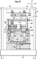
- FIG. 10 and 11 Another embodiment of the magnet embedded core manufacturing device 60 is described with reference to Figures 10 and 11 . It is to be noted that in Figures 10 and 11 , the parts corresponding to those in Figures 4 and 6 are denoted by the same reference signs as those in Figures 4 and 6 , and the description thereof is omitted.
- each pressing member 120 consisting of a rod-like member has a base end 120A fixed to the first plate 12 by means of a screw 122 and a free end 120B extending through a through hole 36 formed in the second plate 14 of the rotor core retaining jig 10 so as to be capable of contacting against a bottom surface 110A of the second member 110.
- the magnet embedded core manufacturing device 60 may be arranged upside down.
- the gate plate 16 and the cull plate 18 may be configured by a single plate-shaped member.
- the solid resin used in the present invention does not have to be in the form of blocks, and may be in the forms of pellet, powder or granule.
- the resin exemplarily consisted of thermosetting resin, but the present invention is not limited to this, and thermoplastic resin may also be used.
- thermoplastic resin is used, the curing step is performed as a cooling step, instead of the thermal curing step used for the thermosetting resin.
- the magnet 5 in each magnet insertion hole 4 was exemplarity offset in the inward direction.
- the position of the magnet 5 in each magnet insertion hole 4 can be freely changed.
- the closure members 26 do not necessarily have to be provided corresponding to the respective magnet insertion holes 4, and may be divided corresponding to respective sets of adjoining multiple magnet insertion holes 4 or corresponding to respective sets of magnet insertion holes 4 that correspond to magnetic poles, and the compression coil springs 28 may be provided corresponding to the respective closure members 26.
- the closure member 26 may be divided into multiple closure members each corresponding to at least one magnet insertion hole 4, and the compression springs 28 may be provided corresponding to the respective closure members 26.
- the arrangement and number of the coupling members 30 may be other than those shown in the foregoing embodiments.
- the driving of the push rods 88, the pistons 96, etc. does not have to be performed using hydraulic pressure, and may be performed electrically using an electromagnetic mechanism, etc.
- Each magnet 5 may be placed centrally in the corresponding magnet insertion hole 4 in plan view. Also, the entire device may be arranged upside down.
- constituent element of the manufacturing method for the magnet embedded core of the present invention shown in the foregoing embodiments are not entirely essential, but may be suitably omitted or substituted without departing from the scope of the present invention.
Landscapes
- Engineering & Computer Science (AREA)
- Power Engineering (AREA)
- Manufacturing & Machinery (AREA)
- Mechanical Engineering (AREA)
- Permanent Field Magnets Of Synchronous Machinery (AREA)
- Manufacture Of Motors, Generators (AREA)
Applications Claiming Priority (1)
| Application Number | Priority Date | Filing Date | Title |
|---|---|---|---|
| PCT/JP2018/037977 WO2020075275A1 (ja) | 2018-10-11 | 2018-10-11 | ロータコア保持治具、磁石埋込み型コアの製造装置及び製造方法 |
Publications (3)
| Publication Number | Publication Date |
|---|---|
| EP3664263A1 true EP3664263A1 (de) | 2020-06-10 |
| EP3664263A4 EP3664263A4 (de) | 2020-06-10 |
| EP3664263B1 EP3664263B1 (de) | 2021-11-24 |
Family
ID=66934436
Family Applications (2)
| Application Number | Title | Priority Date | Filing Date |
|---|---|---|---|
| EP18899035.2A Active EP3664263B1 (de) | 2018-10-11 | 2018-10-11 | Vorrichtung zum halten eines rotorkerns sowie vorrichtung und verfahren zur herstellung eines magneteingebetteten kerns |
| EP19871196.2A Active EP3787162B1 (de) | 2018-10-11 | 2019-03-12 | Einstellvorrichtung für rotorkernhaltewerkzeug |
Family Applications After (1)
| Application Number | Title | Priority Date | Filing Date |
|---|---|---|---|
| EP19871196.2A Active EP3787162B1 (de) | 2018-10-11 | 2019-03-12 | Einstellvorrichtung für rotorkernhaltewerkzeug |
Country Status (6)
| Country | Link |
|---|---|
| US (3) | US11532973B2 (de) |
| EP (2) | EP3664263B1 (de) |
| JP (5) | JP6533635B1 (de) |
| CN (3) | CN110754031B (de) |
| DE (1) | DE112019001984T5 (de) |
| WO (3) | WO2020075275A1 (de) |
Cited By (1)
| Publication number | Priority date | Publication date | Assignee | Title |
|---|---|---|---|---|
| EP4521607A3 (de) * | 2020-08-31 | 2025-07-16 | General Electric Company | Magnetkernmontagewerkzeuge sowie systeme und verfahren zur montage einer magnetkernanordnung |
Families Citing this family (28)
| Publication number | Priority date | Publication date | Assignee | Title |
|---|---|---|---|---|
| WO2020075275A1 (ja) * | 2018-10-11 | 2020-04-16 | 黒田精工株式会社 | ロータコア保持治具、磁石埋込み型コアの製造装置及び製造方法 |
| EP3952075B1 (de) | 2019-03-28 | 2025-12-03 | Aisin Corporation | Verfahren zur herstellung eines motorkerns |
| WO2021065614A1 (ja) | 2019-09-30 | 2021-04-08 | アイシン・エィ・ダブリュ株式会社 | ロータコアの製造方法およびロータコアの製造システム |
| US12132361B2 (en) | 2019-09-30 | 2024-10-29 | Aisin Corporation | Rotor core manufacturing method and rotor core manufacturing system |
| JP7395916B2 (ja) * | 2019-09-30 | 2023-12-12 | 株式会社アイシン | ロータコアの製造方法およびロータコアの製造装置 |
| JP7375475B2 (ja) * | 2019-10-31 | 2023-11-08 | 株式会社アイシン | ロータの製造方法 |
| CN112018977B (zh) * | 2020-08-04 | 2025-06-17 | 浙江联宜电机有限公司 | 机壳与磁瓦粘合辅助装置 |
| JP7493469B2 (ja) * | 2021-01-29 | 2024-05-31 | 株式会社三井ハイテック | 回転電機のコア部製造方法及びコア部製造装置 |
| CN112975314B (zh) * | 2021-02-05 | 2023-02-10 | 扬州京柏自动化科技有限公司 | 磁铁组装设备 |
| JP7447856B2 (ja) * | 2021-03-30 | 2024-03-12 | ニデック株式会社 | Ipmモータ用ロータの製造方法及びipmモータ用ロータ製造装置 |
| NL2028010B1 (en) * | 2021-04-19 | 2022-10-31 | Boschman Tech Bv | Rotor Core Manufacturing Method, and rotor core molding system therefore |
| KR102713946B1 (ko) * | 2021-08-30 | 2024-10-07 | 주식회사 비엠씨 | 모터의 적층 코어의 마그네트 고정용 사출 성형 장치 |
| KR102686250B1 (ko) * | 2021-09-06 | 2024-07-18 | 주식회사 비엠씨 | 로터 코어 제조 장치 |
| KR102686251B1 (ko) * | 2021-09-06 | 2024-07-18 | 주식회사 비엠씨 | 로터 코어의 마그넷 몰딩 장치 |
| KR102804896B1 (ko) * | 2021-09-13 | 2025-05-08 | 대원강업주식회사 | 모터코어의 제조장치 |
| KR102804897B1 (ko) * | 2021-09-13 | 2025-05-08 | 대원강업주식회사 | 모터코어의 제조장치 |
| CN114204761B (zh) * | 2021-11-11 | 2023-09-01 | 中船重工电机科技股份有限公司 | 轮缘推进器上的永磁电机转子磁钢的便捷表贴方法 |
| CN114123685B (zh) * | 2022-01-24 | 2022-04-19 | 新乡职业技术学院 | 一种机电一体化电机安装辅助装置 |
| US20250205946A1 (en) * | 2022-03-31 | 2025-06-26 | Nhk Spring Co., Ltd. | Motor core manufacturing device and motor core manufacturing method |
| CN115635268B (zh) * | 2022-09-28 | 2026-02-06 | 华南智能机器人创新研究院 | 一种磁钢上料机构及转子磁钢装配机 |
| WO2024128230A1 (ja) * | 2022-12-12 | 2024-06-20 | 日本発條株式会社 | モータコアの製造装置及びモータコアの製造方法 |
| EP4439944A1 (de) * | 2023-03-02 | 2024-10-02 | Grob-Werke GmbH & Co. KG | Blechpaket-werkstückträger sowie verwendungen desselben in einer harzversiegelungsvorrichtung und einem harzversiegelungsverfahren |
| WO2024204064A1 (ja) * | 2023-03-24 | 2024-10-03 | 日本発條株式会社 | モータコアの製造装置及びモータコアの製造方法 |
| CN117564663B (zh) * | 2024-01-15 | 2024-04-05 | 恒景泰(深圳)科技有限公司 | 一种电磁铁自动化装配装置 |
| WO2025206065A1 (ja) * | 2024-03-28 | 2025-10-02 | 日本発條株式会社 | パレット部材及びモータの製造方法 |
| WO2026074628A1 (ja) * | 2024-10-02 | 2026-04-09 | Astemo株式会社 | 回転電機 |
| CN119030248B (zh) * | 2024-10-29 | 2025-02-07 | 常州三协电机股份有限公司 | 一种电机位置磁环快速定位装置 |
| CN121649724A (zh) * | 2026-02-06 | 2026-03-13 | 宁波恒宏磁业有限公司 | 一种无线充电座定位磁铁组件的磁铁安装装置 |
Family Cites Families (35)
| Publication number | Priority date | Publication date | Assignee | Title |
|---|---|---|---|---|
| JPS6225843A (ja) * | 1985-07-25 | 1987-02-03 | Matsushita Electric Works Ltd | ロ−タ−の製造方法 |
| US7275299B2 (en) * | 2002-07-30 | 2007-10-02 | Aisin Aw Co., Ltd. | Motor manufacturing process |
| CN1707914A (zh) * | 2004-06-09 | 2005-12-14 | 乐金电子(天津)电器有限公司 | 感应电动机的旋转轴及其组装方法 |
| JPWO2006022392A1 (ja) | 2004-08-25 | 2008-05-08 | 株式会社ミツバ | フライホイールに形成された突起のシェービング装置および突起のシェービング方法 |
| JP2006211865A (ja) * | 2005-01-31 | 2006-08-10 | Mitsui High Tec Inc | 回転子積層鉄心の製造装置及びその製造方法 |
| JP2007159342A (ja) | 2005-12-08 | 2007-06-21 | Fanuc Ltd | 電動機のロータの作製に使用される型 |
| WO2012026003A1 (ja) * | 2010-08-25 | 2012-03-01 | トヨタ自動車株式会社 | 回転子 |
| JP5805385B2 (ja) * | 2010-12-14 | 2015-11-04 | 株式会社三井ハイテック | 積層鉄心の製造方法 |
| JP5681027B2 (ja) * | 2011-04-12 | 2015-03-04 | 株式会社三井ハイテック | 積層鉄心の製造方法 |
| JP5794848B2 (ja) * | 2011-07-19 | 2015-10-14 | 株式会社三井ハイテック | 積層鉄心の製造方法 |
| HUE054387T2 (hu) * | 2011-11-29 | 2021-09-28 | Sumitomo Bakelite Co | Gyantakompozíció rögzítés céljára, rotor, személygépkocsi, és eljárás rotor elõállítására |
| JP5855515B2 (ja) * | 2012-04-03 | 2016-02-09 | 株式会社三井ハイテック | 回転子積層鉄心の製造方法 |
| JP6013683B2 (ja) * | 2012-05-22 | 2016-10-25 | 株式会社三井ハイテック | 積層鉄心の製造方法及び装置 |
| JP5496255B2 (ja) * | 2012-05-31 | 2014-05-21 | 三菱電機株式会社 | 磁石式回転電機の回転子の製造方法およびその製造装置 |
| JP5998733B2 (ja) * | 2012-08-08 | 2016-09-28 | アイシン・エィ・ダブリュ株式会社 | 回転電機用ロータの樹脂充填装置 |
| JP6028469B2 (ja) | 2012-08-31 | 2016-11-16 | アピックヤマダ株式会社 | モールド金型及びモータコアの樹脂モールド方法 |
| JP6037270B2 (ja) | 2012-10-09 | 2016-12-07 | アピックヤマダ株式会社 | モータコアの樹脂モールド方法 |
| JP5981295B2 (ja) * | 2012-10-12 | 2016-08-31 | 株式会社三井ハイテック | 積層鉄心の樹脂封止方法 |
| JP5984092B2 (ja) * | 2012-10-25 | 2016-09-06 | アピックヤマダ株式会社 | モールド金型及びモータコアの樹脂モールド方法 |
| JP6040508B2 (ja) | 2012-10-31 | 2016-12-07 | アピックヤマダ株式会社 | 樹脂モールド装置及びモータコアの樹脂モールド方法 |
| JP6449530B2 (ja) * | 2013-01-15 | 2019-01-09 | 株式会社三井ハイテック | 回転子積層鉄心の製造方法 |
| EP2961040B1 (de) * | 2013-02-20 | 2019-05-08 | Mitsubishi Electric Corporation | Elektromotor mit eingebetteten permanentmagneten |
| JP6322924B2 (ja) | 2013-08-08 | 2018-05-16 | 日産自動車株式会社 | 回転電機用ロータとその製造方法 |
| JPWO2015053368A1 (ja) * | 2013-10-11 | 2017-03-09 | アピックヤマダ株式会社 | 樹脂モールド装置及びモータコアの樹脂モールド方法 |
| JP6069250B2 (ja) * | 2014-03-28 | 2017-02-01 | 本田技研工業株式会社 | ロータ製造装置およびロータ製造方法 |
| JP6322519B2 (ja) * | 2014-08-19 | 2018-05-09 | 株式会社三井ハイテック | モータコアの樹脂封止方法及びこれに用いる装置 |
| WO2016147211A1 (ja) * | 2015-03-13 | 2016-09-22 | 黒田精工株式会社 | 磁石埋め込み型コアの樹脂充填方法および樹脂充填装置 |
| JP6572623B2 (ja) * | 2015-05-14 | 2019-09-11 | アイシン・エィ・ダブリュ株式会社 | 樹脂充填方法 |
| US11201526B2 (en) * | 2016-04-13 | 2021-12-14 | Kuroda Precision Industries Ltd. | Resin sealing device and resin sealing method for manufacturing magnet embedded core |
| EP3444927B1 (de) * | 2016-04-13 | 2024-04-10 | Kuroda Precision Industries Ltd. | Verfahren zur herstellung eines eingebettete magneten umfassenden, laminierten eisenkerns für einen rotor or stator |
| JP6410776B2 (ja) * | 2016-10-06 | 2018-10-24 | 本田技研工業株式会社 | ロータ製造方法 |
| JP6180607B2 (ja) | 2016-10-20 | 2017-08-16 | アピックヤマダ株式会社 | 樹脂モールド装置及びモータコアの樹脂モールド方法 |
| JP6597594B2 (ja) | 2016-12-27 | 2019-10-30 | トヨタ自動車株式会社 | 回転子製造装置 |
| CN207124538U (zh) * | 2017-07-15 | 2018-03-20 | 江阴江信电机材料有限公司 | 一种内置转子铁芯片的叠装夹具 |
| WO2020075275A1 (ja) * | 2018-10-11 | 2020-04-16 | 黒田精工株式会社 | ロータコア保持治具、磁石埋込み型コアの製造装置及び製造方法 |
-
2018
- 2018-10-11 WO PCT/JP2018/037977 patent/WO2020075275A1/ja not_active Ceased
- 2018-10-11 US US16/478,650 patent/US11532973B2/en active Active
- 2018-10-11 JP JP2019515378A patent/JP6533635B1/ja active Active
- 2018-10-11 CN CN201880017134.0A patent/CN110754031B/zh active Active
- 2018-10-11 EP EP18899035.2A patent/EP3664263B1/de active Active
-
2019
- 2019-03-12 CN CN201980036388.1A patent/CN112204863B/zh active Active
- 2019-03-12 US US15/734,250 patent/US11264872B2/en active Active
- 2019-03-12 EP EP19871196.2A patent/EP3787162B1/de active Active
- 2019-03-12 WO PCT/JP2019/009998 patent/WO2020075323A1/ja not_active Ceased
- 2019-03-12 JP JP2020549936A patent/JP7202391B2/ja active Active
- 2019-03-22 DE DE112019001984.8T patent/DE112019001984T5/de active Pending
- 2019-03-22 WO PCT/JP2019/012041 patent/WO2020075324A1/ja not_active Ceased
- 2019-03-22 US US17/049,137 patent/US11258340B2/en active Active
- 2019-03-22 JP JP2020549937A patent/JP7212695B2/ja active Active
- 2019-03-22 CN CN201980029056.0A patent/CN112055934A/zh active Pending
-
2022
- 2022-12-23 JP JP2022206832A patent/JP7405940B2/ja active Active
-
2023
- 2023-12-14 JP JP2023210840A patent/JP7606587B2/ja active Active
Cited By (1)
| Publication number | Priority date | Publication date | Assignee | Title |
|---|---|---|---|---|
| EP4521607A3 (de) * | 2020-08-31 | 2025-07-16 | General Electric Company | Magnetkernmontagewerkzeuge sowie systeme und verfahren zur montage einer magnetkernanordnung |
Also Published As
| Publication number | Publication date |
|---|---|
| US20210242756A1 (en) | 2021-08-05 |
| WO2020075275A1 (ja) | 2020-04-16 |
| JP2024015401A (ja) | 2024-02-01 |
| CN110754031B (zh) | 2021-05-11 |
| EP3787162A1 (de) | 2021-03-03 |
| JP7202391B2 (ja) | 2023-01-11 |
| JP2023024709A (ja) | 2023-02-16 |
| CN110754031A (zh) | 2020-02-04 |
| EP3787162A4 (de) | 2022-01-19 |
| EP3787162B1 (de) | 2026-01-07 |
| WO2020075323A1 (ja) | 2020-04-16 |
| US20210234440A1 (en) | 2021-07-29 |
| WO2020075324A1 (ja) | 2020-04-16 |
| CN112055934A (zh) | 2020-12-08 |
| CN112204863A (zh) | 2021-01-08 |
| JP6533635B1 (ja) | 2019-06-19 |
| CN112204863B (zh) | 2024-12-31 |
| EP3664263B1 (de) | 2021-11-24 |
| US11258340B2 (en) | 2022-02-22 |
| US11264872B2 (en) | 2022-03-01 |
| JP7212695B2 (ja) | 2023-01-25 |
| JPWO2020075324A1 (ja) | 2021-09-02 |
| JPWO2020075275A1 (ja) | 2021-02-15 |
| EP3664263A4 (de) | 2020-06-10 |
| US11532973B2 (en) | 2022-12-20 |
| DE112019001984T5 (de) | 2020-12-31 |
| US20210194338A1 (en) | 2021-06-24 |
| JPWO2020075323A1 (ja) | 2021-09-02 |
| JP7405940B2 (ja) | 2023-12-26 |
| JP7606587B2 (ja) | 2024-12-25 |
Similar Documents
| Publication | Publication Date | Title |
|---|---|---|
| EP3664263B1 (de) | Vorrichtung zum halten eines rotorkerns sowie vorrichtung und verfahren zur herstellung eines magneteingebetteten kerns | |
| US11201527B2 (en) | Device, method, and jig for manufacturing magnet embedded core | |
| EP3444928B1 (de) | Harzdichtungsvorrichtung und harzdichtungsverfahren für einen inneren magnetkern | |
| US9819251B2 (en) | Resin sealing method of motor core | |
| US11588384B2 (en) | Device and method for manufacturing magnet embedded core | |
| CN101379682A (zh) | 转子制造方法 | |
| US11356003B2 (en) | Manufacturing device for magnet embedded core | |
| JP2006197693A (ja) | 回転子積層鉄心の製造装置及び製造方法 | |
| KR20220049224A (ko) | 로터 코어의 마그네트를 수지로 몰딩하기 위한 장치 | |
| KR102780105B1 (ko) | 적층코어의 제조방법 | |
| JP5357217B2 (ja) | 回転子積層鉄心の製造方法 |
Legal Events
| Date | Code | Title | Description |
|---|---|---|---|
| STAA | Information on the status of an ep patent application or granted ep patent |
Free format text: STATUS: UNKNOWN |
|
| STAA | Information on the status of an ep patent application or granted ep patent |
Free format text: STATUS: THE INTERNATIONAL PUBLICATION HAS BEEN MADE |
|
| PUAI | Public reference made under article 153(3) epc to a published international application that has entered the european phase |
Free format text: ORIGINAL CODE: 0009012 |
|
| STAA | Information on the status of an ep patent application or granted ep patent |
Free format text: STATUS: REQUEST FOR EXAMINATION WAS MADE |
|
| STAA | Information on the status of an ep patent application or granted ep patent |
Free format text: STATUS: EXAMINATION IS IN PROGRESS |
|
| 17P | Request for examination filed |
Effective date: 20190719 |
|
| A4 | Supplementary search report drawn up and despatched |
Effective date: 20200210 |
|
| AK | Designated contracting states |
Kind code of ref document: A1 Designated state(s): AL AT BE BG CH CY CZ DE DK EE ES FI FR GB GR HR HU IE IS IT LI LT LU LV MC MK MT NL NO PL PT RO RS SE SI SK SM TR |
|
| AX | Request for extension of the european patent |
Extension state: BA ME |
|
| 17Q | First examination report despatched |
Effective date: 20200605 |
|
| 17Q | First examination report despatched |
Effective date: 20200616 |
|
| GRAP | Despatch of communication of intention to grant a patent |
Free format text: ORIGINAL CODE: EPIDOSNIGR1 |
|
| STAA | Information on the status of an ep patent application or granted ep patent |
Free format text: STATUS: GRANT OF PATENT IS INTENDED |
|
| RIC1 | Information provided on ipc code assigned before grant |
Ipc: H02K 15/03 20060101AFI20210517BHEP Ipc: H02K 1/27 20060101ALN20210517BHEP |
|
| DAV | Request for validation of the european patent (deleted) | ||
| DAX | Request for extension of the european patent (deleted) | ||
| INTG | Intention to grant announced |
Effective date: 20210609 |
|
| GRAS | Grant fee paid |
Free format text: ORIGINAL CODE: EPIDOSNIGR3 |
|
| GRAA | (expected) grant |
Free format text: ORIGINAL CODE: 0009210 |
|
| STAA | Information on the status of an ep patent application or granted ep patent |
Free format text: STATUS: THE PATENT HAS BEEN GRANTED |
|
| AK | Designated contracting states |
Kind code of ref document: B1 Designated state(s): AL AT BE BG CH CY CZ DE DK EE ES FI FR GB GR HR HU IE IS IT LI LT LU LV MC MK MT NL NO PL PT RO RS SE SI SK SM TR |
|
| REG | Reference to a national code |
Ref country code: GB Ref legal event code: FG4D |
|
| REG | Reference to a national code |
Ref country code: AT Ref legal event code: REF Ref document number: 1450621 Country of ref document: AT Kind code of ref document: T Effective date: 20211215 |
|
| REG | Reference to a national code |
Ref country code: DE Ref legal event code: R096 Ref document number: 602018027316 Country of ref document: DE |
|
| REG | Reference to a national code |
Ref country code: IE Ref legal event code: FG4D |
|
| REG | Reference to a national code |
Ref country code: LT Ref legal event code: MG9D |
|
| REG | Reference to a national code |
Ref country code: NL Ref legal event code: MP Effective date: 20211124 |
|
| REG | Reference to a national code |
Ref country code: AT Ref legal event code: MK05 Ref document number: 1450621 Country of ref document: AT Kind code of ref document: T Effective date: 20211124 |
|
| PG25 | Lapsed in a contracting state [announced via postgrant information from national office to epo] |
Ref country code: RS Free format text: LAPSE BECAUSE OF FAILURE TO SUBMIT A TRANSLATION OF THE DESCRIPTION OR TO PAY THE FEE WITHIN THE PRESCRIBED TIME-LIMIT Effective date: 20211124 Ref country code: LT Free format text: LAPSE BECAUSE OF FAILURE TO SUBMIT A TRANSLATION OF THE DESCRIPTION OR TO PAY THE FEE WITHIN THE PRESCRIBED TIME-LIMIT Effective date: 20211124 Ref country code: FI Free format text: LAPSE BECAUSE OF FAILURE TO SUBMIT A TRANSLATION OF THE DESCRIPTION OR TO PAY THE FEE WITHIN THE PRESCRIBED TIME-LIMIT Effective date: 20211124 Ref country code: BG Free format text: LAPSE BECAUSE OF FAILURE TO SUBMIT A TRANSLATION OF THE DESCRIPTION OR TO PAY THE FEE WITHIN THE PRESCRIBED TIME-LIMIT Effective date: 20220224 Ref country code: AT Free format text: LAPSE BECAUSE OF FAILURE TO SUBMIT A TRANSLATION OF THE DESCRIPTION OR TO PAY THE FEE WITHIN THE PRESCRIBED TIME-LIMIT Effective date: 20211124 |
|
| PG25 | Lapsed in a contracting state [announced via postgrant information from national office to epo] |
Ref country code: IS Free format text: LAPSE BECAUSE OF FAILURE TO SUBMIT A TRANSLATION OF THE DESCRIPTION OR TO PAY THE FEE WITHIN THE PRESCRIBED TIME-LIMIT Effective date: 20220324 Ref country code: SE Free format text: LAPSE BECAUSE OF FAILURE TO SUBMIT A TRANSLATION OF THE DESCRIPTION OR TO PAY THE FEE WITHIN THE PRESCRIBED TIME-LIMIT Effective date: 20211124 Ref country code: PT Free format text: LAPSE BECAUSE OF FAILURE TO SUBMIT A TRANSLATION OF THE DESCRIPTION OR TO PAY THE FEE WITHIN THE PRESCRIBED TIME-LIMIT Effective date: 20220324 Ref country code: PL Free format text: LAPSE BECAUSE OF FAILURE TO SUBMIT A TRANSLATION OF THE DESCRIPTION OR TO PAY THE FEE WITHIN THE PRESCRIBED TIME-LIMIT Effective date: 20211124 Ref country code: NO Free format text: LAPSE BECAUSE OF FAILURE TO SUBMIT A TRANSLATION OF THE DESCRIPTION OR TO PAY THE FEE WITHIN THE PRESCRIBED TIME-LIMIT Effective date: 20220224 Ref country code: NL Free format text: LAPSE BECAUSE OF FAILURE TO SUBMIT A TRANSLATION OF THE DESCRIPTION OR TO PAY THE FEE WITHIN THE PRESCRIBED TIME-LIMIT Effective date: 20211124 Ref country code: LV Free format text: LAPSE BECAUSE OF FAILURE TO SUBMIT A TRANSLATION OF THE DESCRIPTION OR TO PAY THE FEE WITHIN THE PRESCRIBED TIME-LIMIT Effective date: 20211124 Ref country code: HR Free format text: LAPSE BECAUSE OF FAILURE TO SUBMIT A TRANSLATION OF THE DESCRIPTION OR TO PAY THE FEE WITHIN THE PRESCRIBED TIME-LIMIT Effective date: 20211124 Ref country code: GR Free format text: LAPSE BECAUSE OF FAILURE TO SUBMIT A TRANSLATION OF THE DESCRIPTION OR TO PAY THE FEE WITHIN THE PRESCRIBED TIME-LIMIT Effective date: 20220225 Ref country code: ES Free format text: LAPSE BECAUSE OF FAILURE TO SUBMIT A TRANSLATION OF THE DESCRIPTION OR TO PAY THE FEE WITHIN THE PRESCRIBED TIME-LIMIT Effective date: 20211124 |
|
| PG25 | Lapsed in a contracting state [announced via postgrant information from national office to epo] |
Ref country code: SM Free format text: LAPSE BECAUSE OF FAILURE TO SUBMIT A TRANSLATION OF THE DESCRIPTION OR TO PAY THE FEE WITHIN THE PRESCRIBED TIME-LIMIT Effective date: 20211124 Ref country code: SK Free format text: LAPSE BECAUSE OF FAILURE TO SUBMIT A TRANSLATION OF THE DESCRIPTION OR TO PAY THE FEE WITHIN THE PRESCRIBED TIME-LIMIT Effective date: 20211124 Ref country code: RO Free format text: LAPSE BECAUSE OF FAILURE TO SUBMIT A TRANSLATION OF THE DESCRIPTION OR TO PAY THE FEE WITHIN THE PRESCRIBED TIME-LIMIT Effective date: 20211124 Ref country code: EE Free format text: LAPSE BECAUSE OF FAILURE TO SUBMIT A TRANSLATION OF THE DESCRIPTION OR TO PAY THE FEE WITHIN THE PRESCRIBED TIME-LIMIT Effective date: 20211124 Ref country code: DK Free format text: LAPSE BECAUSE OF FAILURE TO SUBMIT A TRANSLATION OF THE DESCRIPTION OR TO PAY THE FEE WITHIN THE PRESCRIBED TIME-LIMIT Effective date: 20211124 Ref country code: CZ Free format text: LAPSE BECAUSE OF FAILURE TO SUBMIT A TRANSLATION OF THE DESCRIPTION OR TO PAY THE FEE WITHIN THE PRESCRIBED TIME-LIMIT Effective date: 20211124 |
|
| REG | Reference to a national code |
Ref country code: DE Ref legal event code: R097 Ref document number: 602018027316 Country of ref document: DE |
|
| PLBE | No opposition filed within time limit |
Free format text: ORIGINAL CODE: 0009261 |
|
| STAA | Information on the status of an ep patent application or granted ep patent |
Free format text: STATUS: NO OPPOSITION FILED WITHIN TIME LIMIT |
|
| PG25 | Lapsed in a contracting state [announced via postgrant information from national office to epo] |
Ref country code: AL Free format text: LAPSE BECAUSE OF FAILURE TO SUBMIT A TRANSLATION OF THE DESCRIPTION OR TO PAY THE FEE WITHIN THE PRESCRIBED TIME-LIMIT Effective date: 20211124 |
|
| 26N | No opposition filed |
Effective date: 20220825 |
|
| PG25 | Lapsed in a contracting state [announced via postgrant information from national office to epo] |
Ref country code: SI Free format text: LAPSE BECAUSE OF FAILURE TO SUBMIT A TRANSLATION OF THE DESCRIPTION OR TO PAY THE FEE WITHIN THE PRESCRIBED TIME-LIMIT Effective date: 20211124 |
|
| PG25 | Lapsed in a contracting state [announced via postgrant information from national office to epo] |
Ref country code: MC Free format text: LAPSE BECAUSE OF FAILURE TO SUBMIT A TRANSLATION OF THE DESCRIPTION OR TO PAY THE FEE WITHIN THE PRESCRIBED TIME-LIMIT Effective date: 20211124 |
|
| REG | Reference to a national code |
Ref country code: CH Ref legal event code: PL |
|
| REG | Reference to a national code |
Ref country code: BE Ref legal event code: MM Effective date: 20221031 |
|
| PG25 | Lapsed in a contracting state [announced via postgrant information from national office to epo] |
Ref country code: LU Free format text: LAPSE BECAUSE OF NON-PAYMENT OF DUE FEES Effective date: 20221011 |
|
| P01 | Opt-out of the competence of the unified patent court (upc) registered |
Effective date: 20230605 |
|
| PG25 | Lapsed in a contracting state [announced via postgrant information from national office to epo] |
Ref country code: LI Free format text: LAPSE BECAUSE OF NON-PAYMENT OF DUE FEES Effective date: 20221031 Ref country code: CH Free format text: LAPSE BECAUSE OF NON-PAYMENT OF DUE FEES Effective date: 20221031 |
|
| PG25 | Lapsed in a contracting state [announced via postgrant information from national office to epo] |
Ref country code: BE Free format text: LAPSE BECAUSE OF NON-PAYMENT OF DUE FEES Effective date: 20221031 |
|
| PG25 | Lapsed in a contracting state [announced via postgrant information from national office to epo] |
Ref country code: IE Free format text: LAPSE BECAUSE OF NON-PAYMENT OF DUE FEES Effective date: 20221011 |
|
| PG25 | Lapsed in a contracting state [announced via postgrant information from national office to epo] |
Ref country code: HU Free format text: LAPSE BECAUSE OF FAILURE TO SUBMIT A TRANSLATION OF THE DESCRIPTION OR TO PAY THE FEE WITHIN THE PRESCRIBED TIME-LIMIT; INVALID AB INITIO Effective date: 20181011 |
|
| PG25 | Lapsed in a contracting state [announced via postgrant information from national office to epo] |
Ref country code: CY Free format text: LAPSE BECAUSE OF FAILURE TO SUBMIT A TRANSLATION OF THE DESCRIPTION OR TO PAY THE FEE WITHIN THE PRESCRIBED TIME-LIMIT Effective date: 20211124 |
|
| PG25 | Lapsed in a contracting state [announced via postgrant information from national office to epo] |
Ref country code: MK Free format text: LAPSE BECAUSE OF FAILURE TO SUBMIT A TRANSLATION OF THE DESCRIPTION OR TO PAY THE FEE WITHIN THE PRESCRIBED TIME-LIMIT Effective date: 20211124 |
|
| PG25 | Lapsed in a contracting state [announced via postgrant information from national office to epo] |
Ref country code: TR Free format text: LAPSE BECAUSE OF FAILURE TO SUBMIT A TRANSLATION OF THE DESCRIPTION OR TO PAY THE FEE WITHIN THE PRESCRIBED TIME-LIMIT Effective date: 20211124 |
|
| PG25 | Lapsed in a contracting state [announced via postgrant information from national office to epo] |
Ref country code: MT Free format text: LAPSE BECAUSE OF FAILURE TO SUBMIT A TRANSLATION OF THE DESCRIPTION OR TO PAY THE FEE WITHIN THE PRESCRIBED TIME-LIMIT Effective date: 20211124 |
|
| PGFP | Annual fee paid to national office [announced via postgrant information from national office to epo] |
Ref country code: IT Payment date: 20250922 Year of fee payment: 8 |
|
| PGFP | Annual fee paid to national office [announced via postgrant information from national office to epo] |
Ref country code: GB Payment date: 20250828 Year of fee payment: 8 |
|
| PGFP | Annual fee paid to national office [announced via postgrant information from national office to epo] |
Ref country code: FR Payment date: 20250908 Year of fee payment: 8 |
|
| PGFP | Annual fee paid to national office [announced via postgrant information from national office to epo] |
Ref country code: DE Payment date: 20250902 Year of fee payment: 8 |
|
| REG | Reference to a national code |
Ref country code: DE Ref legal event code: R082 Ref document number: 602018027316 Country of ref document: DE Representative=s name: PUSCHMANN BORCHERT KAISER KLETTNER PATENTANWAE, DE Ref country code: DE Ref legal event code: R082 Ref document number: 602018027316 Country of ref document: DE Representative=s name: PATCARE PATENTANWAELTE PARTNERSCHAFT MBB, DE |