EP3664433A1 - Dispositif de traitement d'informations, procédé de traitement d'informations, programme, et objectif interchangeable - Google Patents
Dispositif de traitement d'informations, procédé de traitement d'informations, programme, et objectif interchangeable Download PDFInfo
- Publication number
- EP3664433A1 EP3664433A1 EP18863036.2A EP18863036A EP3664433A1 EP 3664433 A1 EP3664433 A1 EP 3664433A1 EP 18863036 A EP18863036 A EP 18863036A EP 3664433 A1 EP3664433 A1 EP 3664433A1
- Authority
- EP
- European Patent Office
- Prior art keywords
- facet
- image
- images
- lenses
- lens
- Prior art date
- Legal status (The legal status is an assumption and is not a legal conclusion. Google has not performed a legal analysis and makes no representation as to the accuracy of the status listed.)
- Withdrawn
Links
Images


Classifications
-
- H—ELECTRICITY
- H04—ELECTRIC COMMUNICATION TECHNIQUE
- H04N—PICTORIAL COMMUNICATION, e.g. TELEVISION
- H04N23/00—Cameras or camera modules comprising electronic image sensors; Control thereof
- H04N23/70—Circuitry for compensating brightness variation in the scene
- H04N23/72—Combination of two or more compensation controls
-
- G—PHYSICS
- G03—PHOTOGRAPHY; CINEMATOGRAPHY; ANALOGOUS TECHNIQUES USING WAVES OTHER THAN OPTICAL WAVES; ELECTROGRAPHY; HOLOGRAPHY
- G03B—APPARATUS OR ARRANGEMENTS FOR TAKING PHOTOGRAPHS OR FOR PROJECTING OR VIEWING THEM; APPARATUS OR ARRANGEMENTS EMPLOYING ANALOGOUS TECHNIQUES USING WAVES OTHER THAN OPTICAL WAVES; ACCESSORIES THEREFOR
- G03B19/00—Cameras
- G03B19/02—Still-picture cameras
- G03B19/04—Roll-film cameras
- G03B19/07—Roll-film cameras having more than one objective
-
- G—PHYSICS
- G03—PHOTOGRAPHY; CINEMATOGRAPHY; ANALOGOUS TECHNIQUES USING WAVES OTHER THAN OPTICAL WAVES; ELECTROGRAPHY; HOLOGRAPHY
- G03B—APPARATUS OR ARRANGEMENTS FOR TAKING PHOTOGRAPHS OR FOR PROJECTING OR VIEWING THEM; APPARATUS OR ARRANGEMENTS EMPLOYING ANALOGOUS TECHNIQUES USING WAVES OTHER THAN OPTICAL WAVES; ACCESSORIES THEREFOR
- G03B7/00—Control of exposure by setting shutters, diaphragms or filters, separately or conjointly
- G03B7/08—Control effected solely on the basis of the response, to the intensity of the light received by the camera, of a built-in light-sensitive device
- G03B7/091—Digital circuits
-
- G—PHYSICS
- G03—PHOTOGRAPHY; CINEMATOGRAPHY; ANALOGOUS TECHNIQUES USING WAVES OTHER THAN OPTICAL WAVES; ELECTROGRAPHY; HOLOGRAPHY
- G03B—APPARATUS OR ARRANGEMENTS FOR TAKING PHOTOGRAPHS OR FOR PROJECTING OR VIEWING THEM; APPARATUS OR ARRANGEMENTS EMPLOYING ANALOGOUS TECHNIQUES USING WAVES OTHER THAN OPTICAL WAVES; ACCESSORIES THEREFOR
- G03B7/00—Control of exposure by setting shutters, diaphragms or filters, separately or conjointly
- G03B7/20—Control of exposure by setting shutters, diaphragms or filters, separately or conjointly in accordance with change of lens
-
- H—ELECTRICITY
- H04—ELECTRIC COMMUNICATION TECHNIQUE
- H04N—PICTORIAL COMMUNICATION, e.g. TELEVISION
- H04N23/00—Cameras or camera modules comprising electronic image sensors; Control thereof
- H04N23/50—Constructional details
- H04N23/55—Optical parts specially adapted for electronic image sensors; Mounting thereof
-
- H—ELECTRICITY
- H04—ELECTRIC COMMUNICATION TECHNIQUE
- H04N—PICTORIAL COMMUNICATION, e.g. TELEVISION
- H04N23/00—Cameras or camera modules comprising electronic image sensors; Control thereof
- H04N23/60—Control of cameras or camera modules
-
- H—ELECTRICITY
- H04—ELECTRIC COMMUNICATION TECHNIQUE
- H04N—PICTORIAL COMMUNICATION, e.g. TELEVISION
- H04N23/00—Cameras or camera modules comprising electronic image sensors; Control thereof
- H04N23/60—Control of cameras or camera modules
- H04N23/67—Focus control based on electronic image sensor signals
-
- H—ELECTRICITY
- H04—ELECTRIC COMMUNICATION TECHNIQUE
- H04N—PICTORIAL COMMUNICATION, e.g. TELEVISION
- H04N5/00—Details of television systems
- H04N5/76—Television signal recording
Definitions
- the present technology relates to an information processing apparatus, an information processing method, a program, and an interchangeable lens.
- the present technology relates to an information processing apparatus, an information processing method, a program, and an interchangeable lens that make it possible to easily obtain images of a plurality of viewpoints, for example.
- NPL 1 describes a refocusing method that uses a camera array including 100 cameras.
- NPL 1 Bennett Wilburn et al. "High Performance Imaging Using Large Camera Arrays"
- Images of a plurality of viewpoints are necessary for performing specific image processing such as the refocusing.
- the present technology has been made in view of the above described situations.
- the present technology makes it possible to easily obtain the images of the plurality of viewpoints.
- An information processing apparatus or a program is an information processing apparatus including: a communication section that receives region specification information for specifying respective regions of a plurality of facet images corresponding to pictures formed of respective light beams collected through a plurality of facet lenses, the respective regions being included in an image captured by one image sensor in a case where a camera body including the image sensor is equipped with an interchangeable lens including the plurality of facet lenses disposed in a manner that the plurality of facet lenses does not overlap each other in an optical axis direction; and a region specification section that specifies the regions of the plurality of facet images respectively corresponding to the plurality of facet lenses in the captured image, on the basis of the region specification information, or a program that causes a computer to function as such an information processing apparatus.
- An information processing method is an information processing method performed by the information processing apparatus, the method including: receiving region specification information for specifying respective regions of a plurality of facet images corresponding to pictures formed of respective light beams collected through a plurality of facet lenses, the respective regions being included in an image captured by one image sensor in a case where a camera body including the image sensor is equipped with an interchangeable lens including the plurality of facet lenses disposed in a manner that the plurality of facet lenses does not overlap each other in an optical axis direction; and specifying the regions of the plurality of facet images respectively corresponding to the plurality of facet lenses in the captured image, on the basis of the region specification information.
- the information processing apparatus, the information processing method, and the program according to the present technology receives region specification information for specifying respective regions of a plurality of facet images corresponding to pictures formed of respective light beams collected through a plurality of facet lenses, the respective regions being included in an image captured by one image sensor in a case where a camera body including the image sensor is equipped with an interchangeable lens including the plurality of facet lenses disposed in a manner that the plurality of facet lenses does not overlap each other in an optical axis direction.
- the regions of the plurality of facet images respectively corresponding to the plurality of facet lenses in the captured image is specified on the basis of the region specification information.
- An interchangeable lens is an interchangeable lens including: a plurality of facet lenses disposed in a manner that the plurality of facet lenses does not overlap each other in an optical axis direction; a storage that stores region specification information for specifying respective regions of a plurality of facet images corresponding to pictures formed of respective light beams collected through the plurality of facet lenses, the respective regions being included in an image captured by one image sensor in a case where the interchangeable lens is mounted on a camera body including the image sensor; and a communication section that transmits the region specification information to an outside.
- the interchangeable lens according to the present technology includes a plurality of facet lenses disposed in a manner that the plurality of facet lenses does not overlap each other in an optical axis direction, and stores region specification information for specifying respective regions of a plurality of facet images corresponding to pictures formed of respective light beams collected through the plurality of facet lenses, the respective regions being included in an image captured by one image sensor in a case where the interchangeable lens is mounted on a camera body including the image sensor.
- the region specification information is transmitted to an outside.
- the information processing apparatus may be an independent apparatus or may be an internal block included in an apparatus.
- FIG. 1 is a perspective view illustrating a configuration example of an embodiment of a camera system to which the present technology is applied.
- the camera system includes a camera body 10 and a multi-eye interchangeable lens 20.
- the multi-eye interchangeable lens 20 is attachable and detachable to and from the camera body 10.
- the camera body 10 includes a camera mount 11.
- the multi-eye interchangeable lens 20 is mounted on the camera body 10 by attaching (a lens mount 22 of) the multi-eye interchangeable lens 20 to the camera mount 11. It is to be noted that a general interchangeable lens other than the multi-eye interchangeable lens 20 is also attachable and detachable to and from the camera body 10.
- the camera body 10 includes an image sensor 51 incorporated therein.
- the image sensor 51 is a complementary metal-oxide-semiconductor (CMOS) image sensor, for example.
- CMOS complementary metal-oxide-semiconductor
- the image sensor 51 captures an image by receiving light beams collected through the multi-eye interchangeable lens 20 or another interchangeable lens mounted on (the camera mount 11 of) the camera body 10 and carrying out photoelectric conversion.
- the image captured by the image sensor 51 is also referred to as a captured image.
- the multi-eye interchangeable lens 20 includes a lens barrel 21 and a lens mount 22.
- a plurality of lenses which are four facet lenses 311, 312, 313, and 314 are disposed in the lens barrel 21 in a manner that the four facet lenses do not overlap each other in an optical axis direction (when viewed from the optical axis direction).
- the four facet lenses 31 1 to 31 4 are disposed at positions of vertices of a rhombus on a two-dimensional plane (parallel to a light receiving surface (an imaging surface) of the image sensor 51) that is perpendicular to the optical axis in the lens barrel 21.
- the facet lenses 311 to 314 collect light beams from a subject on the image sensor 51 of the camera body 10 when the multi-eye interchangeable lens 20 is mounted on the camera body 10.
- the camera body 10 is a so-called single-chip camera including one image sensor 51.
- the camera body 10 it is also possible to use a so-called three-chip camera including a plurality of image sensors, that is, three image sensors for red, green, and blue (RGB), for example.
- the facet lenses 31 1 to 31 4 collect light beams on each of the three image sensors.
- the lens mount 22 is attached to the camera mount 11 of the camera body 10.
- the multi-eye interchangeable lens 20 is equipped with the four facet lenses 311 to 314.
- the number of facet lenses included in the multi-eye interchangeable lens 20 is not limited to four. Any number of facet lenses, such as two, three, five, or more facet lenses may be adopted as long as the number of facet lenses is two or more.
- the plurality facet lenses included in the multi-eye interchangeable lens 20 are disposed at positions of vertices of the rhombus. However, it is also possible to dispose the facet lenses at any position on a two-dimensional plane.
- the plurality of facet lenses included in the multi-eye interchangeable lens 20 it is possible to adopt a plurality of lenses having focal lengths, f-numbers, and other specifications that are different from each other. However, for ease of explanation, a plurality of lenses with the same specifications are adopted here.
- the four facet lenses 31 1 to 31 4 are disposed in a manner that optical axes of the respective facet lenses 31 1 to 31 4 are perpendicular to a light receiving surface of the image sensor 51 when the multi-eye interchangeable lens 20 is mounted on the camera body 10.
- the image sensor 51 captures images corresponding to pictures formed on the light receiving surface of the image sensor 51 by using respective light beams collected through the four facet lenses 31 1 to 31 4 .
- images captured by the one image sensor 51 include four facet images respectively corresponding to the four facet lenses 31 1 to 31 4 (images corresponding to pictures formed by light beams collected through the respective facet lenses 311 to 31 4 ).
- the facet image corresponding to the facet lens 31 i is an image captured by using the position of the facet lens 31 i as a viewpoint. Therefore, the four facet images corresponding to the respective facet lenses 311 to 314 are images captured from different viewpoints.
- FIG. 2 is a rear view illustrating a configuration example of a rear surface of the camera body 10.
- a surface on which the multi-eye interchangeable lens 20 is mounted that is, a surface with the camera mount 11 is regarded as a front surface of the camera body 10.
- the rear surface of the camera body 10 is equipped with a display 54 implemented by a liquid crystal panel, an organic electro-luminescence (EL) panel, or the like, for example.
- the display 54 displays information such as a so-called through image, a menu, or settings for the camera body 10.
- FIG. 3 is a block diagram illustrating an electrical configuration example of the camera system illustrated in FIG. 1 .
- the multi-eye interchangeable lens 20 includes a storage 41 and a communication section 42.
- the storage 41 stores lens information that is information regarding the multi-eye interchangeable lens 20.
- the lens information includes region specification information for specifying respective regions of facet images corresponding to the respective facet lenses 31 1 to 31 4 , the respective regions being included in an image captured by the (one) image sensor 51 in a case where the multi-eye interchangeable lens 20 is mounted on the camera body 10.
- the region information is, for example, information indicating sizes and positions of the facet images included in the captured image, such as coordinates of upper left points (pixels) and lower right points of the facet images included in the captured image, coordinates of predetermined points like the upper left points of the facet images included in the captured image, or sizes (for example, horizontal and vertical sizes) of the facet images.
- the region specification information it is also possible to adopt information (hereinafter, referred to as non-region information) that makes it possible to specify the regions of the respective facet images in the captured image, in addition to the region information.
- the non-region information includes, for example, diameters of respective effective image circles of the facet lenses 31 1 to 31 4 , center positions of the effective image circles, and the like.
- a lens ID of the multi-eye interchangeable lens 20 as the non-region information in a case where the unique lens identification (ID) is allocated to the multi-eye interchangeable lens 20 and a database in which lens IDs are associated with pieces of region information regarding multi-eye interchangeable lenses 20 specified on the basis of the lens IDs is prepared. In this case, it is possible to acquire a piece of the region information regarding the multi-eye interchangeable lens 20 associated with the lens ID by searching the database by using the lens ID as a keyword.
- the communication section 42 communicate with a communication section 57 to be described later of the camera body 10, in a wired or wireless manner. It is to be noted that the communication section 42 additionally makes it possible to communicate with another external device such as a server on the Internet or a personal computer (PC) on a wired or wireless local area network (LAN) by using any communication scheme as necessary.
- a server on the Internet or a personal computer (PC) on a wired or wireless local area network (LAN) by using any communication scheme as necessary.
- PC personal computer
- the communication section 42 communicates with the communication section 57 of the camera body 10, and transmits the lens information stored in the storage 41 to the communication section 57.
- the camera body 10 includes the image sensor 51, a region specification section 52, an image processor 53, the display 54, a storage 55, a controller 56, and the communication section 57.
- the image sensor 51 is a CMOS image sensor.
- the light receiving surface of the image sensor 51 is irradiated with light beams collected through the respective facet lenses 31 1 to 31 4 of the multi-eye interchangeable lens 20 mounted on the camera body 10.
- the image sensor 51 receives the light beams collected through the respective facet lenses 31 1 to 31 4 and carries out the photoelectric conversion. This makes it possible to capture an image including facet images corresponding to the respective facet lenses 31 1 to 31 4 (facet images corresponding to pictures formed by the light beams collected through the respective facet lenses 31 1 to 31 4 ), and supply the captured image to the region specification section 52.
- the region specification section 52 is supplied with the captured image from the image sensor 51, and supplied with the lens information from the communication section 57.
- the lens information has been received by the communication section 57 from the multi-eye interchangeable lens 20.
- the region specification section 52 specifies the regions of the facet images corresponding to the respective facet lenses 31 1 to 31 4 , the regions being included in the captured image supplied from the image sensor 51, and outputs region specification result information indicating results of the region specification.
- the region specification section 52 makes it possible to output, for example, a set of the captured image and the region information indicating the regions of the respective facet images included in the captured image, as the region specification result information.
- the region specification section 52 makes it possible to extract (cut out) the respective facet images from the captured image, and output the respective facet images as the region specification result information.
- the region specification section 52 outputs the respective facet images (here, the respective facet images corresponding to the facet lenses 311 to 314) extracted from the captured image, as the region specification result information.
- the facet images corresponding to the respective facet lenses 31 1 to 31 4 outputted from the region specification section 52 are supplied to the image processor 53 and the controller 56.
- the image processor 53 uses the facet images corresponding to the respective facet lenses 31 1 to 31 4 supplied from the region specification section 52, that is, facet images captured by using the positions of the respective facet lenses 311 to 314 as different viewpoints, performs image processing such as refocusing for generating (reconstituting) an image that focuses on, for example, any subject, and supplies the display 54 and the storage 55 with a process result image obtained as a result of the image processing.
- the display 54 displays, for example, the process result image or the like supplied from the image processor 53 as the through image.
- the storage 55 is implemented by a memory card (not illustrated) or the like.
- the storage 55 stores the process result image supplied from the image processor 53 in response to user operation or the like, for example.
- the controller 56 performs various kinds of control over the camera body 10 and the multi-eye interchangeable lens 20 mounted on the camera body 10. For example, the controller 56 controls exposure and focus by using the facet images supplied from the region specification section 52, and achieves auto exposure (AE) and autofocus (AF).
- AE auto exposure
- AF autofocus
- the communication section 57 communicates with the communication section 42 or the like of the multi-eye interchangeable lens 20 in a wired/wireless manner. It is to be noted that the communication section 57 additionally makes it possible to communicate with another external device such as the server on the Internet or the PC on the wired or wireless LAN by using any communication scheme as necessary.
- the communication section 57 communicates with the communication section 42 of the multi-eye interchangeable lens 20, receives the lens information regarding the multi-eye interchangeable lens 20 transmitted from the communication section 42, and supplies the lens information to the region specification section 52.
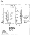
- FIG. 4 is a diagram for describing an overview of image capturing using the multi-eye interchangeable lens 20.
- the image sensor 51 of the camera body 10 equipped with the multi-eye interchangeable lens 20 captures an image including facet images corresponding to pictures formed of light beams collected through the respective facet lenses 31 i .
- a direction from the rear surface side to the front surface side of the camera body 10 is referred to as a z direction (axis), and a direction from left to right obtained when the camera body 10 is facing the z direction is referred to as an x direction, and a direction from bottom to top is referred to as a y direction.
- the left side and the right side of a subject shown in an image are conformed to the left side and the right side of the subject in a real space
- the left sides and the right sides of the facet lenses 31 i are conformed to the left sides and the right sides of the facet images corresponding to the facet lenses 31 i in the captured image. Therefore, hereinafter, positions on the captured image, positions of the facet lenses 31 i , and the left side and the right side of the subject or the like are described on the basis of a state of facing the z direction, that is, an image capturing direction from the rear surface side of the camera body 10 to the subject to be captured an image of, unless otherwise specified.
- FIG. 5 is a diagram illustrating an example of arrangement of the facet lenses 31 1 to 31 4 in the multi-eye interchangeable lens 20 and an image captured by using the multi-eye interchangeable lens 20.
- FIG. 5A is a rear view illustrating the example of arrangement of the facet lenses 31 1 to 31 4 in the multi-eye interchangeable lens 20.
- the facet lenses 31 1 to 31 4 are disposed at positions of vertices of the rhombus on the two-dimensional plane parallel to the light receiving surface of the image sensor 51.
- the facet lens 31 2 is disposed on the right side of the facet lens 31 1 , in FIG. 5 .
- the facet lens 31 3 is disposed on the lower left side of the facet lens 31 1
- the facet lens 31 4 is disposed on the lower right side of the facet lens 31 1 .
- FIG. 5B illustrates an example of an image captured by the image sensor 51 of the camera body 10 equipped with the multi-eye interchangeable lens 20 in which the facet lenses 31 1 to 31 4 are disposed as illustrated in FIG. 5A .
- the image captured by the image sensor 51 of the camera body 10 equipped with the multi-eye interchangeable lens 20 including the plurality of facet lenses 31 1 to 31 4 includes, in addition to a region irradiated with only a light beam passed through a certain facet lens 31 i , an overlapping light receiving region and a non-light receiving region.
- the overlapping light receiving region is a region in the captured image irradiated with both a light beam passed through a certain facet lens 31 i and a light beam passed through another facet lens 31 j .
- the non-light receiving region is a region in the captured image that is not irradiated with any light beams passed through the respective facet lenses 311 to 314.
- the region specification section 52 ( FIG. 3 ) specifies, as a region of a facet image E#i corresponding to a facet lens 31 i , on the basis of the region specification information included in the lens information, a rectangular region of a predetermined size that is centered on (a position corresponding to) an optical axis of the facet lens 31 i among regions corresponding to the facet lenses 31 i in the captured image irradiated with only the light beams passed through the respective facet lenses 31i.
- the facet image E#i corresponding to the facet lens 31 i to be an image that only includes, within a picture formed of a light beam collected through the facet lens 31 i , only a portion that does not overlap other picture formed of a light beam collected through another facet lens 31 j .
- the facet image E#i corresponding to the facet lens 31 i is an image captured by using the position of the facet lens 31 i as a viewpoint in a way similar to an image captured from the position of the facet lens 31 i by using an independent camera.
- FIG. 6 is a flowchart for describing an example of a region specification process performed by the region specification section 52 illustrated in FIG. 3 to specify respective regions of facet images E#i in the captured image.
- Step S11 the region specification section 52 acquires the lens information supplied from the communication section 57, and the process proceeds to Step S12.
- the communication section 57 communicates with the communication section 42 of the multi-eye interchangeable lens 20, receives the lens information regarding the multi-eye interchangeable lens 20 transmitted from the communication section 42, and supplies the lens information to the region specification section 52.
- the region specification section 52 acquires the lens information supplied from the communication section 57.
- Step S12 the region specification section 52 specifies respective regions of facet images E1, E2, E3, and E4 corresponding to the facet lenses 31 1 to 31 4 in the captured image supplied from the image sensor 51, on the basis of the region specification information included in the lens information acquired from the communication section 57, and the process proceeds to Step S13.
- Step S13 the region specification section 52 extracts the facet images E1 to E4 from the captured image, outputs the facet images E1 to E4 as the region specification result information, and ends the process.
- the region specification section 52 makes it possible to output a set of the captured image and the region information indicating the regions of the respective facet images E#i in the captured image as the region specification result information, instead of the facet images E1 to E4.
- the multi-eye interchangeable lens 20 includes the facet lenses 31 1 to 31 4 disposed in a manner that the facet lenses 31 1 to 31 4 do not overlap each other in the optical axis direction (when viewed from the optical axis direction), and transmits the lens information including the region specification information to the camera body 10 serving as the external device, for example.
- the camera body 10 receives the lens information and specifies the regions of the facet images E1 to E4 corresponding to the respective facet lenses 31 1 to 31 4 in the captured image, on the basis of the region specification information included in the lens information. This makes it possible to easily obtain the images of the plurality of viewpoints, that is, the facet images E1 to E4 captured by using the positions of the respective facet lenses 31 1 to 31 4 as the viewpoints.
- FIG. 7 illustrates a display example of through images displayed on the display 54 illustrated in FIG. 3 .
- FIG. 7A illustrates a first display example of the through image.
- the through image it is possible to adopt the image captured by the image sensor 51 as illustrated in FIG. 7A .
- the image processor 53 acquires the image captured by the image sensor 51 from the region specification section 52, supplies the image to the display 54, and causes the image to be displayed.
- FIG. 7B illustrates a second display example of the through image.
- the through image it is possible to adopt one facet image E#i as illustrated in FIG. 7B .
- the image processor 53 selects the one facet image E#i from among the facet images E1 to E4 supplied from the region specification section 52, supplies the one facet image E#i to the display 54, and causes the one facet image E#i to be displayed.
- the one facet image E#i is adopted as the through image
- the through image it is also possible to adopt an image obtained through the refocusing performed by the image processor 53.
- FIG. 8 is a cross-sectional view illustrating an overview of a first optical configuration example of the multi-eye interchangeable lens 20.
- the multi-eye interchangeable lens 20 is assumed to include the three facet lenses 311 to 313, and the three facet lenses 311 to 313 are assumed to be disposed in line in the horizontal direction (the x direction) in a manner that they do not overlap each other when viewed from the optical axis direction (the x direction).
- the multi-eye interchangeable lens 20 does not include an optical component that limits light beams passed through the facet lenses 31 i , a relatively wide range of the light receiving surface of the image sensor 51 is irradiated with the light beams passed through the facet lenses 31 i as illustrated in FIG. 8 .
- the light receiving surface of the image sensor 51 is irradiated with a light beam passed through the facet lens 311 and a light beam passed through the facet lens 312 in a manner that portions of the light beams overlap each other.
- the overlapping light receiving region is formed in the captured image.
- the facet lenses 31 2 and 31 3 that are adjacent to each other.
- the light beam passed through the facet lens 312 that is adjacent to the facet lenses 311 and 313 overlaps the light beam passed through the facet lens 311, and overlaps the light beam passed through the facet lens 313.
- a region in the captured image that may be the region of the facet image E2 corresponding to the facet lens 31 2 and that is irradiated with only the light beam passed through the facet lens 312 becomes smaller than the cases of the facet lenses 31 1 and 31 3 .
- the size of the facet image E2 corresponding to the facet lens 312 is small.
- the sizes of the facet images E1 and E2 also become smaller in a case where the sizes of the facet images E1 to E3 corresponding to the respective facet lenses 31 1 to 31 3 are the same.
- FIG. 9 is a cross-sectional view illustrating an overview of a second optical configuration example of the multi-eye interchangeable lens 20.
- the multi-eye interchangeable lens 20 is also assumed to include the three facet lenses 31 1 to 31 3 , and the three facet lenses 31 1 to 31 3 are assumed to be disposed in line in the horizontal direction in a manner that they do not overlap each other in the optical axis direction in a way similar to the case illustrated in FIG. 8 .
- the multi-eye interchangeable lens 20 includes a diaphragm 71 that limits light beams reaching the image sensor 51 from the respective facet lenses 31 i , as regards the facet lenses 31 1 to 31 3 .
- the diaphragm 71 has circular apertures that limit light beams from the facet lenses 31 i in a manner that a light beam collected through one facet lens 31 i among the facet lenses 311 to 313 does not overlap a light beam collected through another facet lens 31 j among the facet lenses 31 1 to 31 3 .
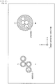
- FIG. 10 is a rear view illustrating an overview of configuration examples of the diaphragms 71 in a case where the multi-eye interchangeable lens 20 includes the four facet lenses 31 1 to 31 4 as illustrated in FIG. 5 .
- FIG. 10A illustrates a first configuration example of the diaphragm 71.
- FIG. 10B illustrates a second configuration example of the diaphragm 71.
- the diaphragm 71 it is possible to adopt one diaphragm that has respective apertures corresponding to the four facet lenses 31 1 to 31 4 and that is installed on one plate, and it is possible to dispose the diaphragm on the rear surfaces of the facet lenses 31 1 to 31 4 .
- FIG. 11 is a perspective view illustrating another configuration example of the multi-eye interchangeable lens 20 including the diaphragm 71.
- the multi-eye interchangeable lens 20 includes five facet lenses 31 1 to 31 5 , and the five facet lenses 31 1 to 31 5 are disposed on a two-dimensional plane in a manner that they do not overlap each other in the optical axis direction.
- the five facet lenses 311 to 31s are disposed such that, for example, the facet lens 311 that is one of the five facet lenses 311 to 31s is disposed as the center and the four other facet lenses 312 to 31s are disposed as vertices of a rectangle surrounding the facet lens 311.
- the diaphragm 71 is disposed on the rear surface side of the facet lenses 31 1 to 31 5 . It is possible to store the diaphragm 71 in the lens barrel 21 of the multi-eye interchangeable lens 20, for example. However, FIG. 11 illustrates the state where the diaphragm 71 is apart from the multi-eye interchangeable lens 20 for facilitating visualization of FIG. 11 .
- rectangular apertures are adopted as the apertures of the diaphragm 71.
- the rectangular apertures are adopted as the apertures of the diaphragm 71, it is possible to limit a region in the light receiving surface of the image sensor 51 irradiated with light passed through a facet lens 31 i , to a rectangular region F.
- each of the facet lenses 31 i of the multi-eye interchangeable lens 20 may be equipped with a lens hood 23 that blocks a portion of the light incident on the facet lens 31 i .
- the lens hood 23 may be fixed to the multi-eye interchangeable lens 20, and may be attachable and detachable to and from the multi-eye interchangeable lens 20.
- FIG. 12 is a flowchart for describing an example of a process (an exposure control process) of exposure control performed by the controller 56 illustrated in FIG. 3 .
- An exposure control method includes a method including: determining a brightness evaluation value that evaluates brightness of the captured image using an image captured by the image sensor 51 ( FIG. 3 ); and controlling exposure time (shutter speed), apertures of the diaphragm, gain (analog gain) of A/D conversion performed on pixel signals by the image sensor 51, and the like in accordance with the bright evaluation value in a manner that the captured image does not include so-called blown-out highlights and achieves appropriate predetermined brightness.
- the image captured by the image sensor 51 may possibly include the non-light receiving region and the overlapping light receiving region as described with reference to FIG. 5 .
- the controller 56 determines a brightness evaluation value and controls exposure by using (an image in a region of) the facet image E#i instead of the captured image (itself).
- the multi-eye interchangeable lens 20 is assumed to include the four facet lenses 311 to 314 and the region specification section 52 is assumed to obtain the four facet images E1 to E4 as illustrated in FIG. 5 .
- the image sensor 51 periodically captures an image and supplies the captured image to the region specification section 52, and the region specification section 52 extracts the four facet images E1 to E4 from the image captured by the image sensor 51.
- Step S21 the controller 56 acquires the four facet images E1 to E4 from the region specification section 52, and the process proceeds to Step S22.
- Step S22 the controller 56 calculates brightness evaluation values that evaluates brightness (evaluation values that evaluates current exposure states) of the facet images E1 to E4 by using some or all of the four facet images E1 to E4, that is, one, two, or more of the four facet images E1 to E4. Subsequently, the process proceeds to Step S23.
- Step S23 the controller 56 controls exposure, that is, exposure time, the diaphragm, and gain in accordance with the brightness evaluation values, and the process proceeds to Step S24.
- Step S24 the controller 56 determines whether to end the AE exposure control.
- Step S24 In a case where the controller 56 determines not to end the exposure control in Step S24, the process returns to Step S21, and similar processes are repeated thereafter.
- Step S24 the exposure control process ends.
- the brightness evaluation values are calculated by using some or all of the facet images E1 to E4. This makes it possible to obtain the brightness evaluation values that are not affected by the non-light receiving region or the overlapping light receiving region, and this makes it possible to appropriately control exposure in accordance with the brightness evaluation values.
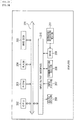
- FIG. 13 is a block diagram illustrating a functional configuration example of sections that perform the refocusing in the image processor 53 illustrated in FIG. 3 .
- the region specification section 52 supplies the facet images E1 to E4 corresponding to the facet lenses 31 1 to 31 4 to the image processor 53.
- the facet images E1 to E4 that correspond to the facet lenses 31 1 to 31 4 and that are supplied from the region specification section 52 to the image processor 53 are images captured by using the positions of the respective facet lenses 31 1 to 31 4 as viewpoints in a way similar to images captured by the independent cameras from positions of the respective facet lenses 31 1 to 31 4 .
- the facet images E1 to E4 are images of different viewpoints.
- the image processor 53 includes a parallax information generator 81, an interpolator 82, a light collection processor 83, and a parameter setting section 84.
- the region specification section 52 supplies the image processor 53 with the facet images E#i of the plurality of viewpoints, which are the images of the plurality of viewpoints.
- the viewpoints regarding the facet images E#i are positions of the facet lenses 31 i .
- the facet images E#i are supplied to the parallax information generator 81 and the interpolator 82.
- the parallax information generator 81 determines parallax information by using the facet images E#i of the plurality of viewpoints supplied from the region specification section 52, and supplies the parallax information to the interpolator 82 and the light collection processor 83.
- the parallax information generator 81 performs a process of determining the parallax information between the respective facet images E#i and other facet images E#j supplied from the region specification section 52, as image processing of the facet images E#i of the plurality of viewpoints.
- the parallax information generator 81 generates a map in which pieces of the parallax information are registered in association with, for example, respective (positions of) pixels in the facet images, and supplies the map to the interpolator 82 and the light collection processor 83.
- the parallax information it is possible to adopt disparity that represents parallax by using the number of pixels, or any information such as a distance in a depth direction corresponding to the parallax or the like, which is convertable into the parallax.
- the disparity is adopted as the parallax information, and the parallax information generator 81 generates a disparity map in which the disparity is registered, as the map in which the parallax information is registered.
- the interpolator 82 uses the plurality of facet images E#i supplied from the region specification section 52 and the disparity map generated by the parallax information generator 81, and generates, through interpolation, images that would be captured from viewpoints other than the viewpoints of the facet images E#i, that is, the positions of the facet lenses 31 i .
- the interpolator 82 uses a plurality of points having substantially equal intervals within a region surrounded straight lines each connecting the viewpoints of the facet images E#i, that is, the positions of the facet lenses 31 i .
- the interpolator 82 generates images of the viewpoints for the interpolation (images that may be captured from the viewpoints for the interpolation) through interpolation.
- the interpolator 82 also makes it possible to generate images of viewpoints for interpolation, as the viewpoints for the interpolation, by using points outside the region surrounded with straight lines each connecting the positions of the facet lenses 3 1 i .
- the interpolator 82 supplies the facet images E#i and the images of the viewpoints for the interpolation, to the light collection processor 83.
- interpolation images the images generated by the interpolator 82 through the interpolation using the facet images are also referred to as interpolation images.
- viewpoint images a set of the facet images E#i and the interpolation images of the viewpoints for the interpolation that have been supplied from the interpolator 82 to the light collection processor 83 is referred to as viewpoint images.
- the interpolator 82 It is possible to consider the interpolation performed by the interpolator 82 as a process of generating viewpoint images of more viewpoints from the facet images E#i of the plurality of viewpoints. It is possible to treat the process of generating the viewpoint images of more viewpoints as a process of reproducing light beams incident from real-space points in the real space.
- the light collection processor 83 uses the viewpoint images of the plurality of viewpoints supplied from the interpolator 82, and performs the light collection process that is image processing corresponding to collecting light beams from a subject and that have been passed through an optical system such as lenses in a real camera on the image sensor or a film and forming pictures of the subject.
- refocusing for generating (reconstituting) an image that focuses on any subject is performed.
- the refocusing is performed by using the disparity map obtained from the parallax information generator 81 and a light collection parameter obtained from the parameter setting section 84.
- the image obtained through the light collection process performed by the light collection processor 83 is outputted as a process result image (to the display 54 and the storage 55 ( FIG. 3 )).
- the parameter setting section 84 sets pixels of one facet image E#i (such as the facet image E1) at a position in designated by user operation performed on an operation section (not illustrated), a predetermined application, or the like, as focus target pixels to be brought into focus (or showing the subject), and supplies the focus target pixels as light collection parameters to the light collection processor 83.
- FIG. 14 is a flowchart for describing an example of image processing performed by the image processor 53 illustrated in FIG. 13 .
- the parallax information generator 81 and the interpolator 82 are supplied with the facet images E#i of the plurality of viewpoints, which are images of the plurality of viewpoints supplied from the region specification section 52.
- Step S51 the parallax information generator 81 in the image processor 53 uses the facet images E#i of the plurality of viewpoints supplied from the region specification section 52, and performs a parallax information generation process of determining parallax information and generating a disparity map on which the parallax information is registered.
- the parallax information generator 81 supplies the interpolator 82 and the light collection processor 83 with the disparity map obtained though the parallax information generation process, and the process proceeds from Step S51 to Step S52.
- Step S52 the interpolator 82 uses the facet images E#i of the plurality of viewpoints supplied from the region specification section 52 and the disparity map generated by the parallax information generator 81, and performs an interpolation process of generating interpolation images of a plurality of viewpoints for interpolation other than the viewpoints of the facet images E#i.
- the interpolator 82 supplies the light collection processor 83 with the facet images E#i of the plurality of viewpoints supplied from the region specification section 52 and the interpolation images of the plurality of viewpoints for the interpolation obtained through the interpolation process, and the process proceeds from Step S52 to Step S53.
- Step S53 the parameter setting section 84 performs a setting process of setting pixels of one viewpoint image (such as the facet image E1) at a position designated by user operation or the like as the focus target pixels to be brought into focus.
- one viewpoint image such as the facet image E1
- the parameter setting section 84 supplies the light collection processor 83 with (information regarding) the focus target pixels obtained through the setting process, as the light collection parameters. Next, the process proceeds from Step S53 to Step S54.
- the focus target pixels are set in accordance with the designation from the user as described above.
- step S54 the light collection processor 83 performs a light collection process corresponding to collection of light beams from the subject onto a virtual sensor (not illustrated) by using the viewpoint images of the plurality of viewpoints supplied from the interpolator 82, the disparity map supplied from the parallax information generator 81, and the focus target pixels serving as the light collection parameters supplied from the parameter setting section 84. Subsequently, the image processing performed by the image processor 53 ends.
- the light collection processor 83 supplies the display 54 with the process result image obtained as a result of the light collection process.
- the virtual sensor that collects the light beams in the light collection process is actually memory (not illustrated), for example.
- pixel values of the viewpoint images of the plurality of viewpoints are integrated in (storage values of) the memory serving as the virtual sensor, as luminance of the light beams collected onto the virtual sensor.
- pixel values of the image obtained through collection of the light beams are determined.
- a reference shift amount BV (described later), which is a pixel shift amount for performing pixel shift on the pixels of the viewpoint images of the plurality of viewpoints.
- the (pixel values of the) pixels of the viewpoint images of the plurality of viewpoints are subjected to the pixel shift in accordance with the reference shift amount BV, and are then integrated.
- each pixel value of a process result image focused on an in-focus point in the real space is determined, and the process result image is generated.
- the in-focus point is a real-space point in the real space at which an image is brought into focus.
- an in-focus plane that is a plane formed of a group of the in-focus points is set by using focus target pixels serving as the light collection parameters supplied from the parameter setting section 84.
- the image processor 53 may include only the light collection processor 83.
- the light collection processor 83 performs the light collection process by using the facet images E#i captured by the region specification section 52 without any interpolation image, it is possible to configure the image processor 53 that does not include the interpolator 82.
- the light collection process is performed by using the interpolation images in addition to the facet images E#i, it is possible to suppress generation of ringing regarding an unfocused subject in the process result image.
- the image processor 53 that does not include the parallax information generator 81.
- the light collection processor 83 sets the in-focus plane in accordance with a predetermined rule, it is possible to configure the image processor 53 that does not include the parameter setting section 84.
- FIG. 15 is a rear view illustrating another configuration example of the multi-eye interchangeable lens 20.
- the multi-eye interchangeable lens 20 includes seven facet lenses 31 1 to 31 7 , and the seven facet lenses 31 1 to 31 7 are disposed on a two-dimensional plane in a manner that they do not overlap each other in the optical axis direction.
- the seven facet lenses 31 1 to 31 7 are disposed in a manner that one of the seven facet lenses 31 1 to 31 7 , for example, facet lens 311, is set as the center and the six other facet lenses 31 2 to 31 7 are disposed around the facet lens 31 1 , the facet lenses 31 2 to 31 7 serving as vertices of a regular hexagon.
- the multi-eye interchangeable lens 20 includes the seven facet lenses 31 1 to 31 7 as illustrated in FIG. 15 is described.
- facet images E#i of a plurality of viewpoints supplied from the region specification section ( FIG. 3 ) to the parallax information generator 81 and the interpolator 82 of the image processor 53 are facet images E1 to E7 of seven viewpoints corresponding to the seven facet lenses 31 1 to 31 7 .
- FIG. 16 is a diagram for describing an example in which the interpolator 82 illustrated in FIG. 13 generates an interpolation image.
- the interpolator 82 sequentially selects pixels of the interpolation image, each as an interpolation target pixel for interpolation.
- the interpolator 82 further selects, as a pixel value calculation image to be used for calculating a pixel value of the interpolation target pixel, all of the facet images E1 to E7 of the seven viewpoints or facet images E#i of some (a plurality of) viewpoints close to the viewpoint of the interpolation image.
- the interpolator 82 uses the disparity map supplied from the parallax information generator 81 and the viewpoint of the interpolation image, and determines a corresponding pixel corresponding to the interpolation target pixel (a pixel in which a spatial point is shown, which is the same point as a spatial point that would be shown on the interpolation target pixel if the imaging is performed from the viewpoint of the interpolation image) from the respective facet images E#i of the plurality of viewpoints selected as the pixel value calculation images.
- the interpolator 82 then weights the pixel values of the corresponding pixels in the facet images E#i of the plurality of viewpoints, and determines a resultant weighted value as the pixel value of the interpolation target pixel.
- the weight used for weighting the pixel value of the corresponding pixel it is possible to adopt a value that is inversely proportional to a distance between the viewpoints of the facet images E#i serving as the pixel value calculation images including the corresponding pixels and the viewpoint of the interpolation image including the interpolation target pixel.
- FIG. 17 is a diagram for describing an example in which the parallax information generator 81 illustrated in FIG. 13 generates a disparity map.
- FIG. 17 illustrates an example of the facet images E1 to E7 corresponding to the facet lenses 31 1 to 31 7 of the region specification section 52.
- the facet images E1 to E7 each show a predetermined object obj as a foreground in front of a predetermined background. Because the facet images E1 to E7 have different viewpoints, for example, the positions (the positions in the facet images) of the objects obj shown in the respective facet images E2 to E7 differ from the position of the object obj shown in the facet image E1 by the amounts corresponding to the differences in the viewpoints.
- the viewpoint (position) of the facet lens 31 i that is, the viewpoint of the viewpoint of the facet image E#i corresponding to the facet lens 31 i is referred to as vp#i.
- the parallax information generator 81 sets the facet image E1 as an image of interest E1 to which attention is paid.
- the parallax information generator 81 sequentially selects pixels in the image of interest E1, each as a pixel of interest to which attention is paid, and detects a corresponding pixel (corresponding point) corresponding to the pixel of interest from each of other facet images E2 to E7.
- Examples of a method of detecting the corresponding pixel corresponding to the pixel of interest in the image of interest E1 from each of the facet images E2 to E7 include a method that uses a principle of triangulation, such as stereo matching or multi-baseline stereo.
- a vector representing positional shift of the corresponding pixel in a facet image E#i from the pixel of interest in the image of interest E1 is referred to as a disparity vector v#i, 1.
- the parallax information generator 81 determines disparity vectors v2, 1 to v7, 1 with regard to the respective facet images E2 to E7. The parallax information generator 81 then takes a majority vote on magnitudes of the disparity vectors v2, 1 to v7, 1, for example, and determines the magnitude of the disparity vector v#i, 1 that is selected by the majority vote as magnitude of disparity of (the position of) the pixel of interest.
- the region specification section 52 obtains vectors that differ in orientation but are equal in magnitude as the disparity vectors v2, 1 to v7, 1, when the real-space point shown in the pixel of interest in the image of interest E1 is also shown in each of the facet images E2 to E7.
- the disparity vectors v2, 1 to v7, 1 in this case are vectors that are equal in magnitude and are in directions opposite to the directions of the viewpoints vp2 to vp7 of the other facet images E2 to E7 relative to the viewpoint vp1 of the image of interest E1.
- an image with occlusion that is, an image in which the real-space point shown in the pixel of interest in the image of interest E1 is hidden behind the foreground.
- a disparity vector v#i, 1 is determined, which has a different magnitude from disparity vectors v#j, 1 of the facet images E#j showing the real-space point shown in the pixel of interest of the image of interest E1.
- the parallax information generator 81 takes a majority vote on magnitudes of the disparity vectors v2, 1 to v7, 1, and determines the magnitude of the disparity vector v#i, 1, which is selected by the majority vote, as magnitude of disparity of the pixel of interest.
- the three disparity vectors v2, 1, v3, 1, and v7, 1 are vectors of the same magnitude. Meanwhile, there are no disparity vectors of the same magnitude among the disparity vectors v4, 1, v5, 1, and v6, 1.
- the magnitude of the three disparity vectors v2, 1, v3, 1, and v7, 1 are determined as the magnitude of the disparity of the pixel of interest.
- the parallax information generator 81 sequentially selects pixels in the image of interest E1, each as a pixel of interest, and determines the magnitude of the disparity.
- the parallax information generator 81 then generates, as a disparity map, a map in which magnitudes of disparities of the pixels of the image of interest E1 are registered in association with the positions (xy coordinates) of the respective pixels.
- the disparity map is a map (table) in which the positions of the pixels are associated with the magnitudes of the disparities of the pixels.
- the majority vote is taken on the disparity vectors after the magnitudes of the disparity vectors are adjusted on the basis of the positional relationship between the viewpoint vp#i of a facet image E#i and viewpoints vp#j of facet images E#j other than the facet image E#i (a positional relationship between the facet lenses 31 i and 31 j ) (a distance between the viewpoint vp#i and the viewpoint vp#j).
- a disparity vector obtained between the image of interest E5 and the facet image E2 is twice greater than a disparity vector obtained between the image of interest E5 and the facet image E1.
- a baseline length that is a distance between the optical axis of the facet lens 31s which has obtained the image of interest E5 and the optical axis of the facet lens 311 which has obtained the facet image E1 is the distance B
- a baseline length between the facet lens 31s which has obtained the image of interest E5 and the facet lens 31 2 which has obtained the facet image E2 is a distance 2B.
- the distance B which is the baseline length between the facet lens 311 and another facet lens 31 i , for example, is referred to as a reference baseline length, which is a criteria for determining a disparity.
- the majority vote on disparity vectors is taken after the magnitudes of the disparity vectors are adjusted in a manner that the baseline lengths is converted into the reference baseline length B.
- the magnitude of the disparity vector obtained between the image of interest E5 and the facet image E1 is adjusted to a magnitude that is one time greater.
- the magnitude of the disparity vector obtained between the image of interest E5 and the facet image E2 is adjusted to a magnification that is 1/2 greater, 1/2 being a value of a ratio of the reference baseline length B to the baseline length 2B between the facet lens 31 5 and the facet lens 31 2 .
- the magnitude of the disparity vector obtained between the image of interest E5 and another facet image E#i is adjusted to a magnitude multiplied by a ratio of the reference baseline length B to a baseline length between the facet lens 31s and the facet lens 31 i .
- a majority vote is then taken on the disparity vectors by using the disparity vectors subjected to the magnitude adjustment.
- the parallax information generator 81 determines a disparity of (each of the pixels of) a facet image E#i with precision of the pixels of the facet image, for example. Further, it is also possible to determine the disparity of the facet image E#i with precision that is equal to or lower than pixels having a higher precision than the pixels of the facet image E#i (for example, the precision of sub pixels such as 1/4 pixels).
- the disparity with the precision that is equal to or lower than the pixels may be used as it is in a process using disparities, or the disparity with the precision that is equal to or lower than the pixels may be used after being converted into integers through rounding down, rounding up, or rounding off.
- magnitudes of disparities registered on the disparity map are hereinafter also referred to as registered disparities.
- the registered disparities are equal to x components of disparities between respective pixels in the facet image E1 and the facet image E5 of the viewpoint that is on the left side of the facet image E1 (vectors representing pixel shift from pixels in the facet image E1 to corresponding pixels in the facet image E5, the corresponding pixels corresponding to the pixels in the facet image E1).
- FIG. 18 is a diagram for describing an overview of the refocusing performed by the light collection processor 83 illustrated in FIG. 13 through the light collection process.
- three images are used in FIG. 18 as viewpoint images of a plurality of viewpoints for the light collection process.
- the three images are the facet image E1, the facet image E2 of the viewpoint that is on the right side of the facet image E1, and the facet image E5 of the viewpoint that is on the left side of the facet image E1.
- FIG. 18 two objects obj1 and obj2 are shown in the facet images E1, E2, and E5.
- the object obj1 is located on a near side
- the object obj2 is located on a far side.
- refocusing is performed to focus on (or put a focus on) the object obj1, and an image viewed from the viewpoint of the facet image E1 is obtained as a process result image after the refocusing.
- DP1 represents a disparity between the pixels showing the object obj1 in the facet image E1 and the viewpoint of the process result image (here, the viewpoint of the facet image E1).
- DP2 represents a disparity between the pixels showing the object obj1 in the facet image E2 and the viewpoint of the process result image
- DP5 represents a disparity between the pixels showing the object obj1 in the facet image E5 and the viewpoint of the process result image.
- the viewpoint of the process result image is the same as the viewpoint of the facet image E1 in FIG. 18 . Therefore, the disparity DP1 between the pixels showing the object obj1 in the facet image E1 and the viewpoint of the process result image is (0, 0).
- pixel shift is performed on the facet images E1, E2, and E5 in accordance with the disparities DP1, DP2, and DP5, and the facet images E1, E2, and E5 subjected to the pixel shift are integrated. This makes it possible to obtain the process result image in which the object obj1 is brought into focus.
- the pixel shift is performed on the facet images E1, E2, and E5 to cancel the respective disparities DP1, DP2, and DP5 (the pixel shift is performed in the opposite directions from the disparities DP1, DP2, and DP5).
- the positions of the pixels showing the object obj1 become identical among the facet images E1, E2, and E5 subjected to the pixel shift.
- the viewpoint of the process result image is the viewpoint of the facet image E1 and the disparity DP1 is (0, 0) as described above, it is not substantially necessary to perform the pixel shift on the facet image E1 here.
- the pixels of viewpoint images of the plurality of viewpoints are subjected to the pixel shift to cancel the disparities between the focus target pixels showing the focus target and the viewpoint of the process result image (here, the viewpoint of the facet image E1). Subsequently, the pixels subjected to the pixel shift are integrated as described above. Thus, the image in which the focus target is refocused is obtained as the process result image.
- FIG. 19 is a diagram for describing an example of disparity conversion.
- the registration disparities registered on the disparity map are identical to the x components of the disparities between the pixels of the facet image E1 and the respective pixels of the facet image E5 of the viewpoint that is on the left side of the facet image E1, outside a region with occlusion.
- disparities of the focus target pixels between the viewpoint image of the viewpoint of interest and the process result image that is, disparities of the focus target pixels between, for example, the viewpoint image of the viewpoint of interest and the facet image E1 are necessary for the pixel shift of the viewpoint image of the viewpoint of interest in the refocusing.
- the direction to the viewpoint of interest from the viewpoint of the facet image E1 which is the viewpoint of the process result image, is indicated by a counterclockwise angle with 0 radian about the x axis.
- the facet lens 312 is located at a distance corresponding to the reference baseline length B in a +x direction from the viewpoint of the facet image E1, which is the viewpoint of the process result image.
- a direction from the viewpoint of the facet image E1, which is the viewpoint of the process result image, to the viewpoint of the facet image E2 corresponding to the facet lens 31 2 is 0 radian.
- the facet lens 313 is located at a distance corresponding to the reference baseline length B in a ⁇ /3 direction from the viewpoint of the facet image E1, which is the viewpoint of the process result image.
- a direction from the viewpoint of the facet image E1, which is the viewpoint of the process result image, to the viewpoint of the facet image E3 corresponding to the facet lens 31 3 is ⁇ /3 radians.
- an interpolation image obtained by the interpolator 82 as an image captured by a virtual lens located at a viewpoint vp of the interpolation image.
- the viewpoint vp of the image captured by the virtual lens is assumed to be located at a distance L in a direction of an angle ⁇ (radian) from the viewpoint of the facet image E1, which is the viewpoint of the process result image.
- a disparity DP of focus target pixels between the facet image E1 and the viewpoint image of the viewpoint vp is determined as, (-(L/B) ⁇ RD ⁇ cos ⁇ , -(L/B) ⁇ RD ⁇ sin ⁇ ), on the basis of the registered disparity RD of the focus target pixels, while taking into account the angle ⁇ , which is the direction of the viewpoint vp.
- Determining the disparity of pixels between the facet image E1 and the viewpoint image of the viewpoint of interest on the basis of a registered disparity RD while taking into account the direction of the viewpoint of interest as described above, that is, converting the registered disparity RD into the disparity of the pixels between the facet image E1 (the process result image) and the viewpoint image of the viewpoint of interest, is also referred to as the disparity conversion.
- the disparities of the focus target pixels between the facet image E1 and the viewpoint images of respective viewpoints are determined on the basis of the registered disparities RD regarding the focus target pixels through the disparity conversion, and the pixel shift is performed on the viewpoint images of the respective viewpoints to cancel the disparities of the focus target pixels.
- the pixel shift is performed on the viewpoint images to cancel the disparities of the focus target pixels between the viewpoint images. Shift amounts of this pixel shift are also referred to as focus shift amounts.
- a viewpoint of an i-th viewpoint image among the viewpoint images of the plurality of viewpoints obtained by the interpolator 82 is also referred to as a viewpoint vp#i, in the description below.
- the focus shift amount of the viewpoint image of the viewpoint vp#i is also referred to as a focus shift amount SV#i.
- the disparity conversion it is possible to determine (a vector serving as) a disparity (-(L/B) ⁇ RD ⁇ cos ⁇ , -(L/B) ⁇ RD ⁇ sin ⁇ ), on the basis of the registered disparity RD, as described above.
- the disparity conversion as arithmetic operation of multiplying the registered disparity RD by each of -(L/B) ⁇ cos ⁇ and -(L/B) ⁇ sin ⁇ , arithmetic operation of multiplying the registered disparity RD ⁇ -1 by each of (L/B) ⁇ cos ⁇ and (L/B) ⁇ sin ⁇ , or the like, for example.
- the disparity conversion is regarded as the arithmetic operation of multiplying the registered disparity RD ⁇ -1 by each of (L/B) ⁇ cos ⁇ and (L/B) ⁇ sin ⁇ , for example.
- a value to be subjected to the disparity conversion which is the registered disparity RD ⁇ - 1 here, is a criteria value for determining the focus shift amounts of the viewpoint images of the respective viewpoints, and is hereinafter also referred to as the reference shift amount BV.
- the focus shift amount is uniquely decided through the disparity conversion of the reference shift amount BV. Accordingly, the pixel shift amounts for performing the pixel shift on the pixels of the viewpoint images of the respective viewpoints in the refocusing are substantially set depending on the setting of the reference shift amount BV.
- the reference shift amount BV used for focusing on the focus target pixels which is the registered disparity RD of the focus target pixels ⁇ -1, is equal to the x component of the disparity of the focus target pixels with respect to the facet image E2.
- FIG. 20 is a flowchart for describing an example of the light collection process for the refocusing.
- Step S71 the light collection processor 83 acquires (information regarding) the focus target pixels serving as the light collection parameters from the parameter setting section 84, and the process proceeds to Step S72.
- the facet image E1 or the like among the facet images E1 to E7 corresponding to the facet lenses 31 1 to 31 7 is displayed on the display 54.
- the parameter setting section 84 sets pixels at the position designated by the user as the focus target pixels, and supplies the light collection processor 83 with (information indicating) the focus target pixels as a light collection parameter.
- step S71 the light collection processor 83 acquires the focus target pixels supplied from the parameter setting section 84 as described above.
- step S72 the light collection processor 83 acquires the registered disparities RD of the focus target pixels registered in the disparity map supplied from the parallax information generator 81.
- the light collection processor 83 sets the reference shift amounts BV in accordance with the registered disparities RD of the focus target pixels.
- the light collection processor 83 sets the registered disparities RD of the focus target pixels ⁇ -1 as the reference shift amounts BV, for example.
- the process proceeds from Step S72 to Step S73.
- step S73 the light collection processor 83 sets, as a process result image, an image corresponding to one of the viewpoint images of the plurality of viewpoints supplied from the interpolator 82, such as an image corresponding to the facet image E1, that is, an image that has the same size as the facet image E1 when viewed from the viewpoint of the facet image E1, and that has initial values of 0 as the pixel values.
- the light collection processor 83 decides, as a pixel of interest, one of pixels that have not been decided as the pixel of interest among pixels in the process target image.
- Step S74 the process proceeds from Step S73 to Step S74.
- step S74 the light collection processor 83 decides, as the viewpoint of interest vp#i, a viewpoint vp#i that has not been decided as the viewpoint of interest (with respect to the pixel of interest) among the viewpoints of the viewpoint images supplied from the interpolator 82.
- the process proceeds to Step S75.
- step S75 the light collection processor 83 determines the focus shift amounts SV#i of respective pixels in the viewpoint image of the viewpoint of interest vp#i, from the reference shift amounts BV.
- the focus shift amounts SV#i are necessary for focusing on the focus target pixels (for putting a focus on a subject shown in the focus target pixels).
- the light collection processor 83 performs the disparity conversion on the reference shift amounts BV while taking into account a direction to the viewpoint of interest vp#i from the viewpoint of the facet image E1, which is the viewpoint of the process result image, and acquires the values (vectors) obtained as a result of the disparity conversion as the focus shift amounts SV#i of the respective pixels of the viewpoint image of the viewpoint of interest vp#i.
- Step S75 the process proceeds from Step S75 to Step S76.
- the light collection processor 83 then performs the pixel shift on the respective pixels in the viewpoint image of the viewpoint of interest vp#i in accordance with the focus shift amounts SV#i, and integrates the pixel value of the pixel at the position of the pixel of interest in the viewpoint image subjected to the pixel shift, with a pixel value of the pixel of interest.
- the light collection processor 83 integrates the pixel value of the pixel at a distance corresponding to the vector (for example, the focus shift amount SV#i ⁇ -1 in this case) corresponding to the focus shift amount SV#i from the position of the pixel of interest among the pixels in the viewpoint image of the viewpoint of interest vp#i, with the pixel value of the pixel of interest.
- Step S76 the process proceeds from Step S76 to Step S77, and the light collection processor 83 determines whether all the viewpoints of the viewpoint images supplied from the interpolator 82 have been set as the viewpoint of interest.
- step S77 In a case where it is determined in step S77 that not all the viewpoints of the viewpoint images supplied from the interpolator 82 have been set as the viewpoint of interest, the process returns to Step S74, and similar processes are repeated thereafter.
- Step S77 in a case where it is determined in step S77 that all the viewpoints of the viewpoint images supplied from the interpolator 82 have been set as the viewpoints of interest, the process proceeds to Step S78.
- step S78 the light collection processor 83 determines whether all of the pixels in the process result image have been set as the pixels of interest.
- step S78 In a case where it is determined in step S78 that not all of the pixels in the process result image have been set as the pixel of interest, the process returns to step S73, and the light collection processor 83 newly decides, as the pixel of interest, one of the pixels that have not been decided as the pixel of interest among the pixels in the process result image, as described above. After that, a process similar to the above is repeated.
- the light collection processor 83 outputs the process result image, and ends the light collection process.
- a plane in which the distance in the depth direction in the real space is constant (does not vary) is set as an in-focus plane, and a process result image focused on a subject located on the in-focus plane (or in the vicinity of the in-focus plane) is generated by using the viewpoint images of the plurality of viewpoints.
- the reference shift amounts BV are set in accordance with the registered disparities RD of the respective focus target pixels, but do not vary in accordance with the pixels of interest or the viewpoint of interest vp#i. Therefore, in the light collection process illustrated in FIG. 20 , the reference shift amounts BV are set regardless of the pixels of interest or the viewpoint of interest vp#i.
- the focus shift amounts SV#i vary with the viewpoint of interest vp#i and the reference shift amount BV.
- the reference shift amounts BV do not vary in accordance with the pixels of interest or the viewpoint of interest vp#i in the light collection process illustrated in FIG. 20 .
- the focus shift amounts SV#i vary with the viewpoint of interest vp#i, but do not vary with the pixel of interest.
- the focus shift amounts SV#i are the same value for respective pixels in a viewpoint image of one viewpoint, regardless of the pixel of interest.
- step S75 for determining the focus shift amounts SV#i forms a loop (the loop from step S73 to step S78) of repeatedly calculating the focus shift amounts SV#i for the same viewpoint vp#i regarding different pixels of interest.
- the focus shift amounts SV#i are the same value for the respective pixels of the viewpoint image of one viewpoint, regardless of the pixel of interest.
- step S75 it is sufficient to perform the process in step S75 for determining the focus shift amounts SV#i only once for one viewpoint.
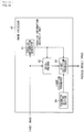
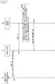
- FIG. 21 is a diagram for describing an example of a process of acquiring region information that indicates a region of a facet image by using a server.
- lens IDs of the multi-eye interchangeable lenses 20 are adopted as the region specification information, and a database is prepared in which lens IDs are associated with pieces of region information regarding multi-eye interchangeable lenses 20 specified on the basis of the lens IDs.
- the communication section 42 of the multi-eye interchangeable lens 20 transmits the lens ID to the camera body 10 as the region specification information stored in the storage 41, in Step S81.
- the communication section 57 of the camera body 10 receives the lens ID of the multi-eye interchangeable lens 20, and transmits the lens ID to, for example, a server 90 on a cloud in Step S91.
- the server 90 receives the lens ID from the camera body 10, searches the database (DB) by using the lens ID as a keyword, and acquires region information indicating the region of the facet image in the image captured by using the multi-eye interchangeable lens 20 specified on the basis of the lens ID, in Step S101.
- Step S102 the server 90 transmits the region information searched from the database, to the camera body 10.
- the communication section 57 of the camera body 10 receives the region information from the server 90 and supplies the region information to the region specification section 52.
- the region specification section 52 specifies a region indicated by the region information supplied from the server 90 as the region of the facet image in the captured image, and extracts the facet image from the captured image.
- the lens ID is transmitted from the multi-eye interchangeable lens 20 to the server 90 via the camera body 10.
- the camera body 10 transmits the captured image to the server 90 together with the lens ID.
- the server 90 it is possible for the server 90 to extract the facet image from the image captured by the camera body 10 in accordance with the region information obtained through the searching that uses the lens ID as the keyword, and transmit the extracted facet image to the camera body 10.
- the camera body 10 that does not include the image processor 53, and it is also possible for the camera body 10 to transmit the captured image or the facet image to the server 90.
- the server 90 it is possible for the server 90 to extract the facet image from the captured image as necessary, and performs image processing similar to the image processing performed by the image processor 53 by using the facet image extracted from the captured image or the facet image transmitted from the camera body 10.
- the server 90 it is possible for the server 90 to transmit a process result image obtained through the image processing, to the camera body 10 or the like.
- FIG. 22 is a diagram for describing details of the exposure control.
- the camera system that controls exposure is assumed to be a single lens camera system, for ease of explanation.
- an evaluation area which is an area to be used for calculating a brightness evaluation value, is set in the captured image as illustrated in FIG. 22 .
- the evaluation area is set to the whole captured image.
- an integrated value of Y signals (luminance signals) of pixels in the evaluation area in the captured image is calculated as the brightness evaluation value. Subsequently, exposure time, the diaphragm, and gain are controlled in accordance with the brightness evaluation value and a preset goal value of the brightness evaluation value.
- FIG. 23 is a block diagram illustrating a configuration example of a camera system having an AE function.
- the camera system includes a lens 111, an image sensor 112, camera signal process large-scale integration (LSI) 113, and a central processing unit (CPU) 114.
- LSI camera signal process large-scale integration
- CPU central processing unit
- the lens 111 collects light from a subject on the image sensor 112.
- the image sensor 112 performs photoelectric conversion on the light passed through the lens 111, and outputs an image captured as a result of the photoelectric conversion, to the camera signal process LSI 113.
- the image sensor 112 includes a color filter with a Bayer arrangement, for example.
- Each of pixels in the captured image outputted from the image sensor 112 includes only any one of a red (R) signal, a green (G) signal, and a blue (B) signal as a pixel value in accordance with the position of the pixel.
- the camera signal process LSI 113 demosaics (interpolates) the image captured by the image sensor 112, and generates the captured image in which the pixels have respective pixel values of the R signal, the G signal, or the B signal (the captured image includes respective planes of the R signal, the G signal, and the B signal).
- the CPU 114 sets the evaluation area, and instructs the camera signal process LSI 113 to generate an evaluation area signal indicating the evaluation area.
- the camera signal process LSI 113 follows the instruction from the CPU 114 and generates the evaluation area signal indicating the evaluation area.
- the camera signal process LSI 113 determines the brightness evaluation value by integrating (performing integration of) Y signals of pixels in the evaluation area (S) in the captured image indicated by the evaluation area signal, and supplies the brightness evaluation value to the CPU 114.
- the CPU 114 calculates a combination of gain and exposure time (shutter speed) of the image sensor 112, for example, in accordance with the brightness evaluation value supplied from the camera signal process LSI 113 and the preset goal value, in a manner that the brightness evaluation value becomes identical to the goal value.
- the Y signals of the captured image as (values proportional to) a product of luminance of the subject, the exposure time of the image sensor 112, and the gain.
- the number of the combinations of the exposure time and the gain for matching the brightness evaluation value, which is the integrated value of the Y signals, and the goal value is infinite.
- the CPU 114 selects a combination of exposure time and gain, which is estimated to be appropriate to a situation, from among the infinite number of combinations of the exposure time and the gain.
- the CPU 114 sets the combination of exposure time and gain, which is estimated to be appropriate, in the image sensor 112. This controls exposure, that is, the exposure time and the gain, and achieves the AE.
- controller 56 ( FIG. 3 ) to perform an exposure control process in a way similar to the camera system illustrated in FIG. 23 .
- FIG. 24 is a block diagram illustrating a configuration example of an embodiment of a computer into which the program for performing the above described series of processes is installed.
- a removable recording medium 211 may be provided as so-called packaged software.
- the removable recording medium 211 may be a flexible disk, a compact disc read only memory (CD-ROM), a magneto-optical (MO) disk, a digital versatile disc (DVD), a magnetic disk, semiconductor memory, or the like, for example.
- the computer includes a central processing unit (CPU) 202, and an input/output interface 210 is coupled to the CPU 202 via a bus 201.
- CPU central processing unit
- the CPU 202 executes the program stored in the read only memory (ROM) 203 in accordance with the instruction.
- the CPU 202 loads the program stored in the hard disk 205 into random access memory (RAM) 204, and executes the program.
- the CPU 202 performs the processes according to the above described flowcharts, or performs the processes by using the above-described structural elements illustrated in the block diagrams.
- the CPU 202 then outputs a result of the process from an output section 206 or transmit the result of the process from a communication section 208 via the input/output interface 210, for example, and records the result of the process on the hard disk 205, as necessary.
- the input section 207 is implemented by a keyboard, a mouse, a microphone, or the like.
- the output section 206 is implemented by a liquid crystal display (LCD), a speaker, or the like.
- processes executed by the computer in accordance with the program may not necessarily be executed chronologically in the order described as a flowchart.
- the processes executed by the computer in accordance with the program also include processes executed in parallel or individually (for example, parallel processes or processes by objects).
- the program may be executed by a single computer (processor), or may be executed in a distributive manner by a plurality of computers. Further, the program may be transferred to a remote computer, and be executed therein.
- the system means an assembly of a plurality of structural elements (apparatuses, modules (parts), and the like), and not all the structural elements have to be provided in the same housing.
- a plurality of apparatuses that are housed in different housings and are coupled to one another via a network is a system, and a single apparatus including a plurality of modules housed in a single housing is also a system.
- the present technology may take a cloud computing configuration in which a plurality of apparatuses shares a function via a network and collaborate in performing a process.
Landscapes
- Engineering & Computer Science (AREA)
- Multimedia (AREA)
- Signal Processing (AREA)
- Physics & Mathematics (AREA)
- General Physics & Mathematics (AREA)
- Studio Devices (AREA)
- Structure And Mechanism Of Cameras (AREA)
- Cameras In General (AREA)
Applications Claiming Priority (2)
| Application Number | Priority Date | Filing Date | Title |
|---|---|---|---|
| JP2017186334 | 2017-09-27 | ||
| PCT/JP2018/033917 WO2019065260A1 (fr) | 2017-09-27 | 2018-09-13 | Dispositif de traitement d'informations, procédé de traitement d'informations, programme, et objectif interchangeable |
Publications (2)
| Publication Number | Publication Date |
|---|---|
| EP3664433A1 true EP3664433A1 (fr) | 2020-06-10 |
| EP3664433A4 EP3664433A4 (fr) | 2021-01-20 |
Family
ID=65901786
Family Applications (1)
| Application Number | Title | Priority Date | Filing Date |
|---|---|---|---|
| EP18863036.2A Withdrawn EP3664433A4 (fr) | 2017-09-27 | 2018-09-13 | Dispositif de traitement d'informations, procédé de traitement d'informations, programme, et objectif interchangeable |
Country Status (5)
| Country | Link |
|---|---|
| US (1) | US20210377432A1 (fr) |
| EP (1) | EP3664433A4 (fr) |
| JP (1) | JPWO2019065260A1 (fr) |
| CN (1) | CN111108742A (fr) |
| WO (1) | WO2019065260A1 (fr) |
Families Citing this family (8)
| Publication number | Priority date | Publication date | Assignee | Title |
|---|---|---|---|---|
| JP7378920B2 (ja) * | 2018-10-16 | 2023-11-14 | キヤノン株式会社 | 光学装置及びそれを備える撮像システム |
| US20230016712A1 (en) * | 2019-12-20 | 2023-01-19 | Sony Group Corporation | Imaging device, information processing method, and program |
| WO2021124941A1 (fr) * | 2019-12-20 | 2021-06-24 | ソニーグループ株式会社 | Dispositif d'imagerie, procédé de traitement d'informations, programme, et lentille amovible |
| US20220408021A1 (en) * | 2019-12-20 | 2022-12-22 | Sony Group Corporation | Information processing device and method, imaging apparatus and method, program, and interchangeable lens |
| US11381730B2 (en) * | 2020-06-25 | 2022-07-05 | Qualcomm Incorporated | Feature-based image autofocus |
| JP7646446B2 (ja) * | 2021-05-13 | 2025-03-17 | キヤノン株式会社 | 画像処理方法、画像処理装置、プログラム、学習済みモデルの製造方法、および画像処理システム |
| US20230308627A1 (en) * | 2021-09-03 | 2023-09-28 | Canon Kabushiki Kaisha | Lens apparatus and image pickup apparatus |
| WO2023058347A1 (fr) * | 2021-10-07 | 2023-04-13 | ソニーグループ株式会社 | Dispositif de traitement d'informations, procédé de traitement d'informations et programme |
Family Cites Families (10)
| Publication number | Priority date | Publication date | Assignee | Title |
|---|---|---|---|---|
| US7557338B2 (en) * | 2006-03-14 | 2009-07-07 | Avago Technologies General Ip (Singapore) Pte. Ltd. | Electronic device with integrated optical navigation module and microlens array therefore |
| JP2012129714A (ja) * | 2010-12-14 | 2012-07-05 | Samsung Yokohama Research Institute Co Ltd | 光学システム及びこれを備える撮像装置 |
| JP2012215631A (ja) * | 2011-03-31 | 2012-11-08 | Fujifilm Corp | 撮像装置及び撮像方法 |
| JP5206853B2 (ja) * | 2011-09-08 | 2013-06-12 | カシオ計算機株式会社 | 補間画像生成装置、再構成画像生成装置、補間画像生成方法及びプログラム |
| JP5832373B2 (ja) * | 2012-05-16 | 2015-12-16 | キヤノン株式会社 | 交換レンズ装置およびカメラ装置 |
| US9395516B2 (en) * | 2012-05-28 | 2016-07-19 | Nikon Corporation | Imaging device |
| JP6126474B2 (ja) * | 2013-06-28 | 2017-05-10 | キヤノン株式会社 | 撮像装置及びその制御方法 |
| JP6239993B2 (ja) * | 2014-02-07 | 2017-11-29 | オリンパス株式会社 | 撮像装置、表示装置、及び制御方法 |
| WO2016199381A1 (fr) * | 2015-06-08 | 2016-12-15 | Canon Kabushiki Kaisha | Appareil et procédé de traitement d'images |
| JP6899630B2 (ja) * | 2016-02-02 | 2021-07-07 | ソニーグループ株式会社 | 交換レンズおよび駆動方法、並びに電子機器 |
-
2018
- 2018-09-13 EP EP18863036.2A patent/EP3664433A4/fr not_active Withdrawn
- 2018-09-13 JP JP2019544558A patent/JPWO2019065260A1/ja not_active Abandoned
- 2018-09-13 WO PCT/JP2018/033917 patent/WO2019065260A1/fr not_active Ceased
- 2018-09-13 CN CN201880060658.8A patent/CN111108742A/zh active Pending
- 2018-09-13 US US16/646,325 patent/US20210377432A1/en not_active Abandoned
Also Published As
| Publication number | Publication date |
|---|---|
| EP3664433A4 (fr) | 2021-01-20 |
| JPWO2019065260A1 (ja) | 2020-11-05 |
| CN111108742A (zh) | 2020-05-05 |
| WO2019065260A1 (fr) | 2019-04-04 |
| US20210377432A1 (en) | 2021-12-02 |
Similar Documents
| Publication | Publication Date | Title |
|---|---|---|
| EP3664433A1 (fr) | Dispositif de traitement d'informations, procédé de traitement d'informations, programme, et objectif interchangeable | |
| US8928736B2 (en) | Three-dimensional modeling apparatus, three-dimensional modeling method and computer-readable recording medium storing three-dimensional modeling program | |
| US10116867B2 (en) | Method and apparatus for displaying a light field based image on a user's device, and corresponding computer program product | |
| JP6223169B2 (ja) | 情報処理装置、情報処理方法およびプログラム | |
| WO2011052064A1 (fr) | Dispositif et procédé de traitement d'informations | |
| JP2013009274A (ja) | 画像処理装置および画像処理方法、プログラム | |
| JP6021489B2 (ja) | 撮像装置、画像処理装置およびその方法 | |
| JP7378219B2 (ja) | 撮像装置、画像処理装置、制御方法、及びプログラム | |
| JP2013025649A (ja) | 画像処理装置及び画像処理方法、プログラム | |
| KR20200124271A (ko) | 촬상 장치, 화상 처리 장치 및 화상 처리 방법 | |
| US20190208109A1 (en) | Image processing apparatus, image processing method, and program | |
| JP2014010783A (ja) | 画像処理装置、画像処理方法およびプログラム | |
| US10965861B2 (en) | Image processing device, image processing method, and program | |
| US10818020B2 (en) | Apparatus and a method for obtaining a registration error map representing a level of sharpness of an image | |
| JP6847097B2 (ja) | 光学取得系によりキャプチャされた画像を符号化するための装置及び方法 | |
| US11012605B2 (en) | Image processing device, image processing method, and program for generating a focused image | |
| US20130076868A1 (en) | Stereoscopic imaging apparatus, face detection apparatus and methods of controlling operation of same | |
| Gąbka | Devising a multi-camera motion capture and processing system for production plant monitoring and operator’s training in virtual reality | |
| US11336803B2 (en) | Information processing apparatus, information processing method, program, and interchangeable lens | |
| JP2014017543A (ja) | 画像処理装置およびその制御方法、並びにプログラム | |
| JP2013110711A (ja) | 画像処理装置および画像処理方法、並びにプログラム | |
| JP2013175821A (ja) | 画像処理装置、画像処理方法およびプログラム | |
| JP5942428B2 (ja) | 再構成画像生成装置、再構成画像生成方法、及びプログラム | |
| CN111193920A (zh) | 一种基于深度学习网络的视频画面立体拼接方法和系统 | |
| JP2020086824A (ja) | 画像処理装置、画像処理方法、撮像装置およびプログラム |
Legal Events
| Date | Code | Title | Description |
|---|---|---|---|
| STAA | Information on the status of an ep patent application or granted ep patent |
Free format text: STATUS: THE INTERNATIONAL PUBLICATION HAS BEEN MADE |
|
| PUAI | Public reference made under article 153(3) epc to a published international application that has entered the european phase |
Free format text: ORIGINAL CODE: 0009012 |
|
| STAA | Information on the status of an ep patent application or granted ep patent |
Free format text: STATUS: REQUEST FOR EXAMINATION WAS MADE |
|
| 17P | Request for examination filed |
Effective date: 20200306 |
|
| AK | Designated contracting states |
Kind code of ref document: A1 Designated state(s): AL AT BE BG CH CY CZ DE DK EE ES FI FR GB GR HR HU IE IS IT LI LT LU LV MC MK MT NL NO PL PT RO RS SE SI SK SM TR |
|
| AX | Request for extension of the european patent |
Extension state: BA ME |
|
| RIC1 | Information provided on ipc code assigned before grant |
Ipc: H04N 5/225 20060101ALI20200916BHEP Ipc: G03B 19/07 20060101ALI20200916BHEP Ipc: G03B 7/20 20060101ALI20200916BHEP Ipc: G03B 7/091 20060101ALI20200916BHEP Ipc: H04N 5/232 20060101AFI20200916BHEP |
|
| DAV | Request for validation of the european patent (deleted) | ||
| DAX | Request for extension of the european patent (deleted) | ||
| A4 | Supplementary search report drawn up and despatched |
Effective date: 20201218 |
|
| RIC1 | Information provided on ipc code assigned before grant |
Ipc: H04N 5/225 20060101ALI20201214BHEP Ipc: G03B 7/091 20060101ALI20201214BHEP Ipc: H04N 5/232 20060101AFI20201214BHEP Ipc: G03B 19/07 20060101ALI20201214BHEP Ipc: G03B 7/20 20060101ALI20201214BHEP |
|
| RAP3 | Party data changed (applicant data changed or rights of an application transferred) |
Owner name: SONY GROUP CORPORATION |
|
| STAA | Information on the status of an ep patent application or granted ep patent |
Free format text: STATUS: THE APPLICATION HAS BEEN WITHDRAWN |
|
| 18W | Application withdrawn |
Effective date: 20220121 |