EP3664436A1 - Bilderfassungsvorrichtung, verfahren zur steuerung der bilderfassungsvorrichtung und berechnungsverfahren - Google Patents
Bilderfassungsvorrichtung, verfahren zur steuerung der bilderfassungsvorrichtung und berechnungsverfahren Download PDFInfo
- Publication number
- EP3664436A1 EP3664436A1 EP19208688.2A EP19208688A EP3664436A1 EP 3664436 A1 EP3664436 A1 EP 3664436A1 EP 19208688 A EP19208688 A EP 19208688A EP 3664436 A1 EP3664436 A1 EP 3664436A1
- Authority
- EP
- European Patent Office
- Prior art keywords
- pixel region
- wavelength band
- region
- light
- filter
- Prior art date
- Legal status (The legal status is an assumption and is not a legal conclusion. Google has not performed a legal analysis and makes no representation as to the accuracy of the status listed.)
- Withdrawn
Links
Images



Classifications
-
- H—ELECTRICITY
- H04—ELECTRIC COMMUNICATION TECHNIQUE
- H04N—PICTORIAL COMMUNICATION, e.g. TELEVISION
- H04N23/00—Cameras or camera modules comprising electronic image sensors; Control thereof
- H04N23/70—Circuitry for compensating brightness variation in the scene
- H04N23/71—Circuitry for evaluating the brightness variation
-
- H—ELECTRICITY
- H04—ELECTRIC COMMUNICATION TECHNIQUE
- H04N—PICTORIAL COMMUNICATION, e.g. TELEVISION
- H04N23/00—Cameras or camera modules comprising electronic image sensors; Control thereof
- H04N23/60—Control of cameras or camera modules
- H04N23/67—Focus control based on electronic image sensor signals
-
- G—PHYSICS
- G02—OPTICS
- G02B—OPTICAL ELEMENTS, SYSTEMS OR APPARATUS
- G02B26/00—Optical devices or arrangements for the control of light using movable or deformable optical elements
- G02B26/02—Optical devices or arrangements for the control of light using movable or deformable optical elements for controlling the intensity of light
- G02B26/023—Optical devices or arrangements for the control of light using movable or deformable optical elements for controlling the intensity of light comprising movable attenuating elements, e.g. neutral density filters
-
- H—ELECTRICITY
- H04—ELECTRIC COMMUNICATION TECHNIQUE
- H04N—PICTORIAL COMMUNICATION, e.g. TELEVISION
- H04N23/00—Cameras or camera modules comprising electronic image sensors; Control thereof
- H04N23/50—Constructional details
- H04N23/55—Optical parts specially adapted for electronic image sensors; Mounting thereof
-
- H—ELECTRICITY
- H04—ELECTRIC COMMUNICATION TECHNIQUE
- H04N—PICTORIAL COMMUNICATION, e.g. TELEVISION
- H04N23/00—Cameras or camera modules comprising electronic image sensors; Control thereof
- H04N23/70—Circuitry for compensating brightness variation in the scene
- H04N23/73—Circuitry for compensating brightness variation in the scene by influencing the exposure time
-
- H—ELECTRICITY
- H04—ELECTRIC COMMUNICATION TECHNIQUE
- H04N—PICTORIAL COMMUNICATION, e.g. TELEVISION
- H04N5/00—Details of television systems
- H04N5/30—Transforming light or analogous information into electric information
- H04N5/33—Transforming infrared radiation
Definitions
- the present invention relates to an image capturing apparatus, a method for controlling an image capturing apparatus, and a calculation method.
- An image capturing apparatus for use in monitoring or the like is required to acquire a clear subject image even in low light, e.g. at nighttime.
- an image capturing apparatus that enables a clear subject image to be acquired even in low light
- an image capturing apparatus has been proposed that uses an image sensor that is sensitive not only to visible light but also to infrared light and enables captured images of visible light and infrared light to be captured (see Japanese Patent Laid-Open No. 2001-45512 ).
- an image capturing apparatus for use in monitoring or the like is required to continue to perform shooting with an in-focus position fixed, in order to continue to constantly monitor a specific shooting region.
- an ordinary imaging optical system has an axial chromatic aberration, and therefore the image-forming position differs depending on the wavelength of incident light.
- FIG. 12 shows a relationship (axial chromatic aberration) between the wavelength of light incident on an imaging optical system and an image-forming position, with the horizontal axis indicating the wavelength of light and the vertical axis indicating the image-forming position.
- the image-forming position differs depending on the wavelength of light incident on the imaging optical system, due to an axial chromatic aberration in the imaging optical system.
- the greater the wavelength differs the greater the image-forming position differs.
- the wavelength of light incident on the imaging optical system is determined by the product of an illumination wavelength of ambient light and spectral reflectance of a subject (hereinafter, "wavelength of ambient light"). For this reason, if an image of a subject is shot with the position of a focus lens fixed, the in-focus position may change as the wavelength of ambient light changes.
- an image capturing apparatus for use in monitoring that is installed at an entrance of a shop or a parking area is required to continue to perform shooting with the in-focus position placed in a specific shooting region (the entrance in this case).
- an industrial image capturing apparatus for use in an assembly process in a factory and an in-vehicle image capturing apparatus for detecting obstacles are also required to continue to perform shooting with the in-focus position placed in a specific shooting region.
- the present invention has been made in consideration of the above situation, and reduces the dependency of an in-focus position on the illumination wavelength of ambient light and the spectral reflectance of a subject when images of visible light and infrared light are shot.
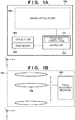
- an image capturing apparatus 100 includes an imaging optical system 101, an image sensor 102, a control unit 103, and an optical filter 104, which is arranged on the imaging optical system 101 side (-z side) relative to the image sensor 102.
- the image sensor 102 is arranged on an optical axis of the imaging optical system 101, and the imaging optical system 101 forms a subject image on the image sensor 102.
- the image sensor 102 is made of an inorganic semiconductor such as Si, InGaAs, or metal oxide, an organic semiconductor, or the like that has absorbability in at least a part of the wavelength band of visible light and in at least a part of the wavelength band of infrared light.
- visible light means light with a wavelength from 380 nm to 750 nm
- infrared light means light with a wavelength from 750 nm to 2500 nm.
- “Having absorbability” means that the extinction coefficient is 1 x 10 -3 or more in a desired wavelength band.
- the absorption edge of Si is 1100 nm, and thus has absorbability in light in the entire wavelength band of visible light and infrared light with a wavelength from 750 nm to 1100 nm.
- FIG. 1B is a schematic diagram that shows a configuration of the imaging optical system 101 according to this embodiment.
- the imaging optical system 101 has a focus adjustment mechanism 105 and a plurality of imaging lenses.
- An in-focus position of the imaging optical system 101 is adjusted by moving the position of a focus lens 106, which is included in the plurality of imaging lenses, in an optical axis direction (Z-axis direction) using the focus adjustment mechanism 105, which has a driving mechanism such as a stepping motor.
- the control unit 103 controls the focus adjustment mechanism 105, drives the image sensor 102, reads out signals from the image sensor 102, and generates an image. Also, the control unit 103 holds a later-described focus lens control table 111.
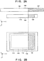
- FIGS. 2A and 2B illustrate a configuration of the optical filter 104 according to the first embodiment that is used in the image capturing apparatus 100 that has the above configuration, and a positional relationship between the optical filter 104 and the image sensor 102.
- FIG. 2A shows the optical filter 104 and the image sensor 102 as viewed from a +Y-axis direction
- FIG. 2B shows the image sensor 102 as viewed from a -Z-axis direction.
- the optical filter 104 has a first filter region 107, which selectively allows the passage of visible light (first wavelength) that is included in a predetermined wavelength band therethrough, and selectively absorbs infrared light (second wavelength) that is included in a predetermined wavelength band that at least partially differs from that of visible light, and a second filter region 108, which allows the passage of both visible light and infrared light therethrough.
- the first filter region 107 is arranged so as to cover a portion of the image sensor 102.
- a pixel region covered by the first filter region 107 will be called a first pixel region 109
- a pixel region covered by the second filter region 108 will be called a second pixel region 110. That is to say, pixels in the second pixel region 110 receives both visible light and infrared light, whereas pixels in the first pixel region 109 only receives visible light due to infrared light being absorbed by the first filter region 107.
- the product of the illumination wavelength of ambient light and the spectral reflectance of a subject (wavelength of ambient light) is estimated based on a difference between the signal level of signals read out from pixels in the first pixel region 109 and the signal level of signals read out from pixels in the second pixel region 110. Then, the focus adjustment mechanism 105 is controlled using the estimation result and the focus lens control table 111. A detailed description will be given below.
- FIG. 3 shows an example of the focus lens control table 111.
- the control unit 103 holds the focus lens control table 111, which indicates a relationship between the distance (shooting distance) at which focus is to be placed and the position of the focus lens 106 that corresponds to the wavelength of ambient light.
- the focus lens control table 111 has positions PVI of the focus lens 106 when visible light is incident on the imaging optical system 101, and positions PIR of the focus lens 106 when infrared light is incident on the imaging optical system 101, with respect to the shooting distances L.
- the positions PVI and PIR may be respectively obtained by performing interpolation between the positions PVI and between the positions PIR corresponding to the distances L before and after the desired distance in the focus lens control table 111, by means of linear interpolation or the like.
- FIG. 3 shows the case where the relationship between the shooting distance L and the positions PVI and PIR is held in the form of a table, the relationship may alternatively be held in the form of an expression, such as a polynomial.
- the pixels in the first pixel region 109 only receive visible light, and the pixels in the second pixel region 110 receive both visible light and infrared light. Accordingly, if a first signal level of signals read out from the pixels in the first pixel region 109 is denoted as S1, and a second signal level of signals read out from the pixels in the second pixel region 110 is denoted as S2, the wavelength of ambient light can be estimated using Equations (1) and (2) below.
- SVI S 1
- SIR S 2 ⁇ S 1
- SVI denotes a visible light component in the wavelength of ambient light
- SIR denotes an infrared light component in the wavelength of ambient light. That is to say, the visible light component (first component) and the infrared light component (second component) that are included in the wavelength of ambient light can be estimated using Equations (1) and (2).
- the first signal level S1 and the second signal level S2 may be signal levels at specific pixels in the first pixel region 109 and the second pixel region 110, or may be the average value or the median value of signal levels at a plurality of pixels. Note that the estimation accuracy increases if the average value or the median value of the signal levels at a plurality of pixels is used.
- FIG. 4A is a schematic diagram for illustrating an example of a pixel region that includes a plurality of pixels to be used to calculate the signal levels according to the first embodiment.
- an imaging optical system has a rotationally-symmetric image-forming capability with respect to its optical axis. Accordingly, so-called shading occurs, that is, the amount of light received by the pixels differs depending on the distance (image height) from the optical axis. For this reason, if the image height of a first wavelength estimation region 109a for obtaining the first signal level S1 is equal to the image height of a second wavelength estimation region 110a for obtaining the second signal level S2, the visible light component and the infrared light component in the wavelength of ambient light can be estimated more accurately. Note that it is assumed here that the image height of the first wavelength estimation region 109a and the image height of the second wavelength estimation region 110a are the image heights of the centroids of the respective regions. The image heights of these regions are allowed to have tolerance of about 10%.
- the exposure timing differs between pixels located in different rows (i.e. pixels with different Y coordinates).
- pixels located in different rows i.e. pixels with different Y coordinates.
- the coordinates (Y coordinates) of the first wavelength estimation region 109a and the second wavelength estimation region 110a in the direction in which pixel signals are read out are the same as shown in FIG.
- the visible light component and the infrared light component in the wavelength of ambient light can be estimated more accurately. Note that it is assumed here that the Y coordinates of the first wavelength estimation region 109a and the second wavelength estimation region 110a are the Y coordinates of the centroids of the respective regions.
- the focus lens control table 111 has the positions PVI of the focus lens for adjusting the in-focus position when visible light is incident, and the positions PIR of the focus lens for adjusting the in-focus position when infrared light is incident.
- a weighted average of a position PVI and a position PIR for a shooting distance L is obtained based on the visible light component SVI and the infrared light component SIR in the wavelength of ambient light, as indicated by Equation (3).
- PMIX PVI ⁇ SVI + PIR ⁇ SIR / SVI + SIR
- the dependency of the in-focus position on the illumination wavelength of ambient light and the spectral reflectance of a subject can be reduced by estimating the visible light component and the infrared light component in the wavelength of ambient light and controlling the position of the focus lens using the estimation result.
- the image quality can be improved.
- FIGS. 2A and 2B show the case where the first pixel region 109 is provided along a side of the image sensor 102 in the +X direction
- the arrangement of the first pixel region 109 and the second pixel region 110 is not limited to the arrangement shown in FIGS. 2A and 2B .
- the first filter region is provided along any one of the sides of the optical filter, since this configuration facilitates manufacturing of the optical filter.
- the ratio of the second pixel region 110 is greater in an effective pixel region 112, which is used to generate an image, in the pixel region 113 of the image sensor 102. The reason will be described below.
- the pixels in the second pixel region 110 receive both visible light and infrared light, whereas the pixels in the first pixel region 109 only receive visible light. Accordingly, the amount of light received by the pixels in the first pixel region 109 is smaller than the amount of light received by the pixels in the second pixel region 110.
- the larger the amount of light received by a pixel the higher the SN ratio of a pixel signal, and thus, the SN ratio of the pixel signals from the second pixel region 110 is higher than that of the pixel signals from the first pixel region 109.
- the quality of an image generated using the pixel signals from the second pixel region 110 is higher than the quality of an image generated using the pixel signals from the first pixel region 109. For this reason, it is more preferable that the ratio of the second pixel region 110 is greater in the effective pixel region 112. Especially, it is yet more preferable that the entire effective pixel region 112 is the second pixel region 110.
- the ratio of the area covered by the first filter region 107 of the optical filter 104 is smaller in the effective pixel region 112 of the image sensor 102, and it is yet more preferable that the effective pixel region 112 is not covered by the first filter region 107.
- the image capturing apparatus 100 has a pixel region outside the effective pixel region 112
- the area of the pixel region 113 of the image sensor 102 is larger than the area of an image circle 101b of the imaging optical system 101.
- the region determined by the image circle 101b of the imaging optical system 101, in the rectangular pixel region 113 of the image sensor 102 is a circular effective pixel region 112, and the remaining region is the pixel region outside the effective pixel region 112.
- the first filter region 107 of the optical filter 104 may be arranged so as to cover a region that includes four corners of the pixel region 113 and not to cover the effective pixel region 112 at the center.
- FIG. 4B shows an example in which a region that includes four corners of the pixel region 113, excluding the effective pixel region 112 at the center, is covered by the first filter region 107.
- the visible light component (first component) and the infrared light component (second component) that are included in the wavelength of ambient light can be estimated using pixel signals from the first pixel region 109, which is not used to generate an image, and pixel signals from the second pixel region 110, which is the effective pixel region 112.
- an image can be generated using pixel signals that are obtained with both visible light and infrared light.
- the dependency of the in-focus position on the illumination wavelength of ambient light and the spectral reflectance of a subject can be reduced, and the image quality can be improved.
- the shooting conditions for the first pixel region 109 and the second pixel region 110 may be the same, or may differ. To reduce the calculation load of calculation of the difference between the first signal level S1 and the second signal level S2 in Equation (2), it is preferable that the shooting conditions for the first pixel region 109 and the second pixel region 110 are the same.
- the amount of light received by the pixels in the first pixel region 109 is smaller than the amount of light received by the pixels in the second pixel region 110. Accordingly, it is preferable that the exposure level in the first pixel region 109 is made higher than the exposure level of the second pixel region 110. Specifically, it is preferable that the accumulation time and analog gain of the pixels in the first pixel region 109 are made higher than the accumulation time and analog gain of the pixels in the second pixel region 110.
- the arrangement shown in FIG. 4C is preferable in the case of changing the accumulation time of the pixels in the first pixel region 109 with respect to the accumulation time of the pixels in the second pixel region 110. That is to say, it is preferable that the boundary (X direction) between the first pixel region 109 and the second pixel region 110 is perpendicular to the direction (Y direction) in which pixel signals are read out in the image sensor 102. The reason will be described below.
- the accumulation time can be more readily controlled if the boundary (X direction) between the first pixel region 109 and the second pixel region 110 of the optical filter 104 is perpendicular to the direction (Y direction) in which pixel signals are read out in the image sensor 102.
- FIGS. 2A and 2B show the case where the optical filter 104 has the first filter region 107 and the second filter region 108
- the optical filter 104 may alternatively have the first filter region 107 only, and the first filter region 107 may be arranged so as to cover a portion of the image sensor 102.
- a configuration may be employed in which the optical filter is made of a material that selectively allows the passage of visible light therethrough and selectively absorbs infrared light, and the optical filter 104 is arranged so as to cover a portion of the image sensor 102.
- the wavelength of ambient light can be estimated by comparing the signal level of signals from the first pixel region 109 and the signal level of signals from the second pixel region 110, similarly to the case in FIGS. 2A and 2B .
- FIG. 5A illustrates a configuration of the optical filter 104 according to the second embodiment and a positional relationship between the optical filter 104 and the image sensor 102 in the second embodiment, and shows the optical filter 104 and the image sensor 102 as viewed from the +Y-axis direction.
- the optical filter 104 has a first filter region 207, which selectively allows the passage of infrared light therethrough and selectively absorbs visible light, and a second filter region 208, which allows the passage of both infrared light and visible light therethrough.
- the first filter region 207 is arranged so as to cover a portion of the image sensor 102, similarly to the arrangement shown in FIG. 2B in the first embodiment.
- a pixel region covered by the first filter region 207 will be called a first pixel region 209
- a pixel region covered by the second filter region 208 will be called a second pixel region 210. That is to say, pixels in the second pixel region 210 receive both visible light and infrared light, whereas pixels in the first pixel region 209 only receives infrared light due to visible light being absorbed by the first filter region 207.
- the wavelength of ambient light is estimated based on the difference between the signal level of signals read out from the pixels in the first pixel region 209 and the signal level of signals read out from pixels in the second pixel region 210.
- the focus adjustment mechanism is controlled using the estimation result and the focus lens control table 111.
- the configuration of the optical filter 104 according to the second embodiment differs from that of the first embodiment, and the method for estimating the wavelength of ambient light differs accordingly. If the signal level of signals read out from the pixels in the first pixel region 209 is denoted as S3, and the signal level of signals read out from the pixels in the second pixel region 110 is denoted as S4, the wavelength of ambient light can be estimated using Equations (4) and (5) below.
- SIR S 3
- SVI S 4 ⁇ S 3
- SVI denotes the visible light component (first component) in the wavelength of ambient light
- SIR denotes the infrared light component (second component) in the wavelength of ambient light, similarly to the above-described Equations (1) and (2).
- the focus lens 106 is driven to the position obtained using Equation (3), similarly to the above-described first embodiment, using the visible light component SVI and the infrared light component SIR that are estimated using Equations (4) and (5).
- the dependency of the in-focus position on the illumination wavelength of ambient light and the spectral reflectance of a subject can be reduced, and the image quality can be improved, similarly to the first embodiment.
- first filter region 207 and the second filter region 208 are not limited to that shown in FIG. 5A .
- first filter region 207 and the second filter region 208 may alternatively be arranged so as to form the arrangements of the first pixel region 109 and the second pixel region 110 that has been described in the above modifications 1 to 3.
- the in-focus position differs depending on the wavelength, not only between visible light and infrared light but also within the infrared light band. Accordingly, the dependency of the in-focus position on the wavelength of ambient light can be reduced by estimating a wavelength distribution in the infrared light component as well as the visible light component (first component) and the infrared light component (second component) in the wavelength of ambient light, and controlling the position of the focus lens 106 in accordance with this estimation.
- FIG. 5B shows the case where the first filter region 207 illustrated in FIG. 5A is divided into a third filter region, which selectively allows the passage of near-infrared light (less than 1100 nm) therethrough, and a fourth filter region, which selectively allows the passage of shortwave infrared light (1100 nm or more) therethrough.
- a pixel region covered by the second filter region 208 will be called a second pixel region 210
- a pixel region covered by the third filter region will be called a third pixel region 214
- a pixel region covered by the fourth filter region will be called a fourth pixel region 215.
- a first signal level of signals read out from pixels in the third pixel region 214 is denoted as S5
- a third signal level of signals read out from pixels in the fourth pixel region 215 is denoted as S6.
- a near-infrared light component SNIR (first component) and a shortwave infrared light component SSWIR (third component) in the wavelength band of infrared light can be estimated in addition to the visible light component SVI (second component) in the wavelength of ambient light, using Equations (6), (7), and (8) below.
- SNIR S 5
- SSWIR S 6
- SVI S 4 ⁇ S 5 ⁇ S 6
- FIG. 6 shows an example of the focus lens control table 111 according to the modification 4.
- positions PVI of the focus lens 106 when visible light is incident on the imaging optical system 101 positions PNIR when near-infrared light is incident thereon, and positions PSWIR when shortwave infrared light is incident thereon are provided with respect to shooting distances L.
- PMIX is calculated using Equation (9) below, using an estimated near-infrared light component SNIR, shortwave infrared light component SSWIR, and visible light component SVI, as well as the focus lens control table 111.
- the dependency of the in-focus position on the wavelength of ambient light can be reduced by moving the focus lens 106 to the position of the calculated PMIX.
- PMIX PVI ⁇ SVI + PNIR ⁇ SNIR + PSWIR ⁇ SSWIR ⁇ SVI + SNIR + SSWIR
- the region that allows the passage of infrared light therethrough includes two regions, namely the region that selectively allows the passage of near-infrared light therethrough and the region that selectively allows the passage of shortwave infrared light therethrough
- the region that allows the passage of infrared light therethrough may alternatively include three or more regions.
- the region that allows the passage of infrared light therethrough may also include a plurality of regions that selectively allows the passage of infrared light having different forms of transmission spectra in the infrared band.
- FIGS. 7A and 7B illustrate a configuration of the optical filter 104 and a positional relationship between the optical filter 104 and the image sensor 102 according to the third embodiment.
- FIG. 7A shows the optical filter 104 and the image sensor 102 as viewed from the +Y-axis direction
- FIG. 7B shows the image sensor 102 as viewed from the -Z-axis direction.
- the optical filter 104 has a first filter region 316, which selectively absorbs infrared light and selectively allows the passage of visible light therethrough, a second filter region 317, which selectively absorbs visible light and selectively allows the passage of infrared light therethrough, and a third filter region 318, which allows the passage of visible light and infrared light therethrough.
- a pixel region covered by the first filter region 316 will be called a first pixel region 319
- a pixel region covered by the second filter region 317 will be called a second pixel region 320
- a pixel region covered by the third filter region 318 will be called a third pixel region 321.
- the image capturing apparatus 100 according to the third embodiment also estimates the wavelength of ambient light based on the difference between the signal levels of signals read out from pixels in the first to third pixel regions 319 to 321, similarly to the image capturing apparatus 100 according to the first and second embodiments.
- the focus adjustment mechanism 105 is controlled using the estimation result and the focus lens control table 111, similarly to the first embodiment.
- the wavelength of ambient light can be estimated as follows. That is to say, the first pixel region 319 only receives visible light, and the second pixel region 320 only receives infrared light.
- the visible light component and the infrared light component in the wavelength of ambient light can be estimated without obtaining the difference in the signal level between a plurality of pixel regions.
- the third embodiment can achieve a reduction in the calculation load of the difference calculation, in addition to the same effects as those of the first and second embodiments.
- the arrangement of the image sensor 102 and the optical filter 104 is not limited to the arrangement shown in FIGS. 7A and 7B . However, as mentioned above, it is preferable that the distances from the optical axis of the imaging optical system to the first pixel region 319 and to the second pixel region 320 coincide with each other, from the viewpoint of shading in the imaging optical system.
- FIG. 8 is a block diagram that shows a schematic diagram of an image capturing apparatus 400 according to the fourth embodiment. Note that, in FIG. 8 , the same elements as those in FIGS. 1A and 1B are assigned the same reference numerals, and a description thereof is omitted.
- the image capturing apparatus 400 differs from the image capturing apparatus 100 shown in FIGS. 1A and 1B in that the image capturing apparatus 400 has a filter driving mechanism 401 that moves the optical filter 104 on a plane perpendicular to the optical axis of the imaging optical system 101 based on the control performed by a control unit 403.
- FIGS. 9A and 9B illustrates a configuration of the optical filter 104 and a positional relationship between the optical filter 104 and the image sensor 102 according to the fourth embodiment, and shows the optical filter 104 and the image sensor 102 as viewed from the +Y axis direction.
- the optical filter 104 according to the fourth embodiment has a first filter region 407, which selectively allows the passage of visible light therethrough and selectively absorbs infrared light, and a second filter region 408, which allows the passage of both visible light and infrared light therethrough.
- the image sensor 102 has a plurality of types of color filters in the pixels, and can acquire a color image. Specifically, the image sensor 102 has pixels in a so-called RGB Bayer array.
- the shooting mode is switched between a shooting mode (day mode) of acquiring a color image and a shooting mode (night mode) in which a clear image can be acquired even in low light while color information is lost, by driving the optical filter 104.
- the first filter region 407 of the optical filter 104 may be arranged by the filter driving mechanism 401 so as to cover the entire pixel region 113 of the image sensor 102, as shown in FIG. 9A .
- the visible light component (first component) and the infrared light component (second component) in the wavelength of ambient light need not be estimated. Accordingly, the position of the focus lens 106 need only be controlled at a position corresponding to the shooting distance, using information regarding the focus lens position when visible light is incident in the focus lens control table 111 shown in FIG. 3 .
- the in-focus position also differs depending on the wavelength in the visible light band. Accordingly, the dependency of the in-focus position on the wavelength of ambient light may also be reduced by estimating the wavelength distribution in the visible light component in the wavelength of ambient light and controlling the position of the focus lens in accordance with the estimated wavelength distribution.
- the wavelength distribution in the visible light component may be estimated based on the signal levels at R pixels, G pixels, and B pixels to control the position of the focus lens 106.
- information may be prepared, such as a focus lens control table or a polynomial that indicates the relationship between the position at which focus is to be placed and the wavelengths of R, G, and B, and a weighted average may be obtained.
- the image capturing apparatus 400 when the image capturing apparatus 400 is used in the night mode, it is preferable to generate an image using pixels that receive both visible light and infrared light.
- the dependency of a shift in the in-focus position on the illumination wavelength of ambient light and the spectral reflectance of a subject is large, and therefore, the visible light component and the infrared light component in the wavelength of ambient light are estimated.
- the first filter region 407 and the second filter region 408 are arranged by the filter driving mechanism 401 so as to cover portions of the pixel region 113 of the image sensor 102, as shown in FIG. 9B .
- the visible light component and the infrared light component in the wavelength of ambient light are estimated using the above-described Equations (1) and (2), using the first signal level S1 at the pixels in a first pixel region 409 that is covered by the first filter region 407, and the second signal level S2 at the pixels in a second pixel region 410 that is covered by the second filter region 408.
- the focus adjustment mechanism 105 is controlled using the estimation result and the focus lens control table 111, similarly to the first embodiment.
- FIGS. 9A and 9B various methods for arranging the first filter region 407 and the second filter region 408 and methods for driving the optical filter 104 are possible.
- a configuration is preferable in which the first filter region 407 and the second filter region 408 are arranged along the direction in which the optical filter 104 is driven (the X direction in the example shown in FIGS. 9A and 9B ), and the filter driving mechanism 401 drives the first filter region 407 and the second filter region 408 in the direction in which these filter regions are arranged (the X direction in the example shown in FIGS. 9A and 9B ).
- this configuration it is possible to simplify the mechanism for driving the optical filter, and also to switch between the day mode of only acquiring visible light and the night mode of estimating the visible light component and the infrared light component in the wavelength of ambient light.
- the fourth embodiment enables an image with higher color reproducibility to be obtained in the day mode, in addition to the same effects as those of the first embodiment.
- the fifth embodiment of the present invention will be described. Note that the schematic configuration of the image capturing apparatus 400 according to the fifth embodiment is the same as that described in the fourth embodiment with reference to FIG. 8 , and a description thereof is omitted here accordingly.
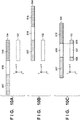
- FIGS. 10A to 10C illustrates a configuration of the optical filter 104 and the arrangement of the optical filter 104 and the image sensor 102 according to the fifth embodiment, and shows the optical filter 104 and the image sensor 102 as viewed from the +Y axis direction.
- the optical filter 104 according to the fifth embodiment has a first filter region 516, which selectively absorbs infrared light and selectively allows the passage of visible light therethrough, a second filter region 517, which selectively absorbs visible light and selectively allows the passage of infrared light therethrough, and a third filter region 518, which allows the passage of visible light and infrared light therethrough.
- the shooting mode of the image capturing apparatus 400 according to the fifth embodiment can be switched to a shooting mode (infrared mode) in which a clear image of a subject at a far distance can be acquired, in addition to the day mode and the night mode, by driving the optical filter 104 shown in FIGS. 10A to 10C .
- a shooting mode infrared mode
- the optical filter 104 is arranged such that the entire pixel region 113 of the image sensor 102 is covered by the first filter region 516, as shown in FIG. 10A .
- the position of the focus lens 106 is controlled similarly to the case of the day mode in the fourth embodiment.
- the optical filter 104 is arranged such that the entire pixel region 113 of the image sensor 102 is covered by the second filter region 517, as shown in FIG. 10B .
- This arrangement makes it possible to restrict the light received by the image sensor 102 to infrared light only. Accordingly, the position of the focus lens 106 need only be controlled at a position corresponding to the shooting distance, using information regarding the focus lens position when infrared light is incident in the focus lens control table 111 shown in FIG. 3 .
- the first filter region 516, the second filter region 517, and the third filter region 518 are arranged so as to cover the pixel region 113 of the image sensor 102 as shown in FIG. 10C .
- the visible light component (first component) and the infrared light component (second component) in the wavelength of ambient light are estimated using pixel signals from the first pixel region 519 that is covered by the first filter region 516 and the second pixel region 520 that is covered by the second filter region 517, similarly to the third embodiment.
- the position of the focus lens 106 is controlled as described in the third embodiment.
- the fifth embodiment enables acquisition of a clear image of a subject at a far distance by selectively receiving infrared light only, in addition to the same effects as those of the fourth embodiment.
- the image capturing apparatus 400 when in the night mode, may also estimate a wavelength distribution in the infrared light component, using a difference in spectral sensitivity characteristics of the R pixels, G pixels, and B pixels in the image sensor 102 in the wavelength band of infrared light.
- FIG. 11 shows respective spectral sensitivity of R, G, and B pixels in the image sensor 102 according to the modification 5.
- the R pixels are most sensitive to infrared light IR1 with shorter wavelengths
- the B pixels is most sensitive to infrared light IR3 with longer wavelengths, in the wavelength band of infrared light.
- all pixels are sensitive to infrared light IR2 with wavelengths between infrared light IR1 and infrared light IR3 to the same degree.
- the spectral sensitivity shown in FIG. 11 is determined by the material and configuration of photoelectric converters in the image sensor 102, and physical properties of color filter materials used in the RGB pixels. Note that the spectral sensitivity of the pixels in the wavelength band of infrared light can be controlled more accurately by mixing coloring matter that has absorbability in a specific wavelength band in infrared light in the color filters.
- the wavelength distribution in the infrared light component in the wavelength of ambient light can also be estimated using signals from a plurality of pixels with different spectral sensitivities in the wavelength band of infrared light. Furthermore, the dependency of the in-focus position on the wavelength of ambient light can be reduced by controlling the position of the focus lens in accordance with the estimation result.
- the signal levels of signals from the R pixels, G pixels, and B pixels in the second pixel region 520 in FIG. 10C are denoted as SvR, SvG, and SvB, respectively.
- the pixel sensitivities of the R, G, and B pixels in the wavelength band IR1 shown in FIG. 11 are denoted respectively as Rir1, Gir1, and Bir1
- the pixel sensitivities of the R, G, and B pixels in the wavelength band IR2 are denoted respectively as Rir2, Gir2, and Bir2
- the pixel sensitivities of the R, G, and B pixels in the wavelength band IR3 are denoted respectively as Rir3, Gir3, and Bir3.
- the components Sir1, Sir2, and Sir3 in the wavelength bands IR1, IR2, and IR3 can be estimated using Equation (12) below.
- Sir 1 Sir 2 Sir 3 R ir 1 R ir 2 R ir 3 G ir 1 G ir 2 G ir 3 B ir 1 B ir 2 B ir 3 ⁇ 1 SvR SvG SvB
- the above description has described an example of reducing the dependency of the in-focus position on the wavelength of ambient light in the night mode by estimating the wavelength distribution in the infrared light component in the night mode, but the same method may also be used in the infrared mode.
- the components Sir1, Sir2, and Sir3 in the wavelength bands IR1, IR2, and IR3 of infrared light in the wavelength of ambient light can be estimated using Equation (12), based on the signal levels of signals from the RGB pixels in the region covered by the second filter region 517.
- Equation (12) the dependency of the in-focus position on the wavelength of ambient light can be reduced in the infrared mode as well.
- an image in the effective pixel region in an image acquired to estimate the wavelength of ambient light is also used as a captured image.
- the position of the optical filter may be changed for between a frame for estimating the wavelength and a frame for acquiring a captured image.
- the first filter region 407 and the second filter region 408 are arranged so as to cover portions of the pixel region 113 of the image sensor 102.
- the first filter region 407 is arranged such that the effective pixel region of the image sensor 102 is not covered by the first filter region 407.
- the first filter region 516, the second filter region 517, and the third filter region 518 are arranged so as to cover the pixel region 113 of the image sensor 102.
- the first filter region 516 and the second filter region 517 of the optical filter are arranged such that the effective pixel region of the image sensor 102 is not covered thereby.
- the driving mode for the image sensor 102 can also be changed between the frames. For example, in a frame for acquiring a captured image, signals are read out from all of the pixels in the image sensor 102 in order to acquire a high-resolution captured image. On the other hand, since the resolution is not required in the mode of estimating the wavelength of ambient light, pixels to be read out can be thinned out to reduce power consumption and increase the frame rate.
- Embodiment(s) of the present invention can also be realized by a computer of a system or apparatus that reads out and executes computer executable instructions (e.g., one or more programs) recorded on a storage medium (which may also be referred to more fully as a 'non-transitory computer-readable storage medium') to perform the functions of one or more of the above-described embodiment(s) and/or that includes one or more circuits (e.g., application specific integrated circuit (ASIC)) for performing the functions of one or more of the above-described embodiment(s), and by a method performed by the computer of the system or apparatus by, for example, reading out and executing the computer executable instructions from the storage medium to perform the functions of one or more of the above-described embodiment(s) and/or controlling the one or more circuits to perform the functions of one or more of the above-described embodiment(s).
- computer executable instructions e.g., one or more programs
- a storage medium which may also be referred to more fully as
- the computer may comprise one or more processors (e.g., central processing unit (CPU), micro processing unit (MPU)) and may include a network of separate computers or separate processors to read out and execute the computer executable instructions.
- the computer executable instructions may be provided to the computer, for example, from a network or the storage medium.
- the storage medium may include, for example, one or more of a hard disk, a random-access memory (RAM), a read only memory (ROM), a storage of distributed computing systems, an optical disk (such as a compact disc (CD), digital versatile disc (DVD), or Blu-ray Disc (BD)TM), a flash memory device, a memory card, and the like.
Landscapes
- Engineering & Computer Science (AREA)
- Multimedia (AREA)
- Signal Processing (AREA)
- Physics & Mathematics (AREA)
- General Physics & Mathematics (AREA)
- Optics & Photonics (AREA)
- Automatic Focus Adjustment (AREA)
- Studio Devices (AREA)
- Focusing (AREA)
- Blocking Light For Cameras (AREA)
- Color Television Image Signal Generators (AREA)
Applications Claiming Priority (1)
| Application Number | Priority Date | Filing Date | Title |
|---|---|---|---|
| JP2018226720A JP7169863B2 (ja) | 2018-12-03 | 2018-12-03 | 撮像装置及びその制御方法、及び演算方法 |
Publications (1)
| Publication Number | Publication Date |
|---|---|
| EP3664436A1 true EP3664436A1 (de) | 2020-06-10 |
Family
ID=68581312
Family Applications (1)
| Application Number | Title | Priority Date | Filing Date |
|---|---|---|---|
| EP19208688.2A Withdrawn EP3664436A1 (de) | 2018-12-03 | 2019-11-12 | Bilderfassungsvorrichtung, verfahren zur steuerung der bilderfassungsvorrichtung und berechnungsverfahren |
Country Status (4)
| Country | Link |
|---|---|
| US (1) | US11108968B2 (de) |
| EP (1) | EP3664436A1 (de) |
| JP (1) | JP7169863B2 (de) |
| CN (1) | CN111263057B (de) |
Families Citing this family (6)
| Publication number | Priority date | Publication date | Assignee | Title |
|---|---|---|---|---|
| CN111726514B (zh) * | 2019-03-20 | 2021-09-28 | 浙江宇视科技有限公司 | 一种摄像机及其昼夜模式切换方法、装置、设备、介质 |
| JP7693289B2 (ja) * | 2020-08-04 | 2025-06-17 | キヤノン株式会社 | 撮像装置 |
| JP7496879B2 (ja) * | 2020-08-20 | 2024-06-07 | 富士フイルム株式会社 | 撮像装置、撮像方法、及びプログラム |
| CN112665618B (zh) * | 2020-12-17 | 2022-05-17 | 安徽中元新材料技术有限公司 | 一种基于形态学的波长敏感模式提取装置及方法 |
| CN113873132B (zh) * | 2021-10-26 | 2024-03-22 | 维沃移动通信有限公司 | 镜头模组、移动终端、拍摄方法和拍摄装置 |
| CN120166277A (zh) * | 2023-12-15 | 2025-06-17 | 三赢科技(深圳)有限公司 | 成像模组及摄像装置 |
Citations (8)
| Publication number | Priority date | Publication date | Assignee | Title |
|---|---|---|---|---|
| JP2001045512A (ja) | 1999-08-04 | 2001-02-16 | Sanyo Electric Co Ltd | 白黒/カラー切換カメラ |
| US20070211155A1 (en) * | 2006-03-08 | 2007-09-13 | Hajime Numata | Imaging apparatus and method of controlling imaging apparatus |
| US20070285540A1 (en) * | 2006-06-01 | 2007-12-13 | Samsung Electronics Co., Ltd. | Image photographing device and method |
| US20130050453A1 (en) * | 2011-08-24 | 2013-02-28 | Fluke Corporation | Thermal imaging camera with range detection |
| US20160198103A1 (en) * | 2014-05-23 | 2016-07-07 | Panasonic Intellectual Property Management Co., Ltd. | Imaging device, imaging system, and imaging method |
| US20180045867A1 (en) * | 2015-04-23 | 2018-02-15 | Fujifilm Corporation | Imaging device, image processing method and program for imaging device |
| EP3340603A1 (de) * | 2016-12-22 | 2018-06-27 | Axis AB | Fokussierung einer überwachungskamera, die eine szene überwacht |
| US20180227490A1 (en) * | 2017-02-03 | 2018-08-09 | Panasonic Intellectual Property Management Co., Ltd. | Method for controlling imaging device, and imaging device |
Family Cites Families (15)
| Publication number | Priority date | Publication date | Assignee | Title |
|---|---|---|---|---|
| JP2004132836A (ja) * | 2002-10-10 | 2004-04-30 | Seiko Precision Inc | 測光機能付き位相差検出装置、測光機能付き測距装置および測光機能付き撮像装置 |
| JP4999494B2 (ja) * | 2007-02-28 | 2012-08-15 | オンセミコンダクター・トレーディング・リミテッド | 撮像装置 |
| JP5178396B2 (ja) * | 2008-08-21 | 2013-04-10 | キヤノン株式会社 | 撮像装置 |
| JP2014048620A (ja) * | 2012-09-04 | 2014-03-17 | Canon Inc | 焦点調節装置、その制御方法、および制御プログラム |
| JP2014075780A (ja) * | 2012-09-14 | 2014-04-24 | Ricoh Co Ltd | 撮像装置及び撮像システム |
| KR101473768B1 (ko) * | 2013-11-28 | 2014-12-24 | 한국과학기술연구원 | 편광 라이트 필드 카메라를 이용한 스페큘러 및 디퓨즈 영상 생성 장치 및 그것의 제어방법 |
| JP6372109B2 (ja) * | 2014-03-11 | 2018-08-15 | リコーイメージング株式会社 | Af機能を備えた撮像装置 |
| KR101783991B1 (ko) * | 2014-04-29 | 2017-10-11 | 한화테크윈 주식회사 | 영상촬영장치에서 개선된 줌트래킹 방법 |
| US9992469B2 (en) * | 2014-06-24 | 2018-06-05 | Hitachi Maxell, Ltd. | Imaging processing device and imaging processing method |
| WO2016158196A1 (ja) * | 2015-03-31 | 2016-10-06 | 富士フイルム株式会社 | 撮像装置及び撮像装置の画像処理方法及びプログラム |
| US10579871B2 (en) * | 2016-02-03 | 2020-03-03 | Hefei Xu | Biometric composite imaging system and method reusable with visible light |
| US10277842B1 (en) * | 2016-11-29 | 2019-04-30 | X Development Llc | Dynamic range for depth sensing |
| JP6849438B2 (ja) * | 2017-01-10 | 2021-03-24 | キヤノン株式会社 | 撮像装置及び撮像装置の制御方法 |
| US10536623B2 (en) * | 2017-03-13 | 2020-01-14 | Lumileds Llc | Imaging device with an improved autofocusing performance |
| JP6989466B2 (ja) * | 2018-09-13 | 2022-01-05 | 株式会社東芝 | 光学フィルタ、撮像装置および測距装置 |
-
2018
- 2018-12-03 JP JP2018226720A patent/JP7169863B2/ja active Active
-
2019
- 2019-11-12 EP EP19208688.2A patent/EP3664436A1/de not_active Withdrawn
- 2019-11-25 US US16/694,138 patent/US11108968B2/en active Active
- 2019-12-03 CN CN201911220409.3A patent/CN111263057B/zh active Active
Patent Citations (8)
| Publication number | Priority date | Publication date | Assignee | Title |
|---|---|---|---|---|
| JP2001045512A (ja) | 1999-08-04 | 2001-02-16 | Sanyo Electric Co Ltd | 白黒/カラー切換カメラ |
| US20070211155A1 (en) * | 2006-03-08 | 2007-09-13 | Hajime Numata | Imaging apparatus and method of controlling imaging apparatus |
| US20070285540A1 (en) * | 2006-06-01 | 2007-12-13 | Samsung Electronics Co., Ltd. | Image photographing device and method |
| US20130050453A1 (en) * | 2011-08-24 | 2013-02-28 | Fluke Corporation | Thermal imaging camera with range detection |
| US20160198103A1 (en) * | 2014-05-23 | 2016-07-07 | Panasonic Intellectual Property Management Co., Ltd. | Imaging device, imaging system, and imaging method |
| US20180045867A1 (en) * | 2015-04-23 | 2018-02-15 | Fujifilm Corporation | Imaging device, image processing method and program for imaging device |
| EP3340603A1 (de) * | 2016-12-22 | 2018-06-27 | Axis AB | Fokussierung einer überwachungskamera, die eine szene überwacht |
| US20180227490A1 (en) * | 2017-02-03 | 2018-08-09 | Panasonic Intellectual Property Management Co., Ltd. | Method for controlling imaging device, and imaging device |
Also Published As
| Publication number | Publication date |
|---|---|
| JP7169863B2 (ja) | 2022-11-11 |
| US20200177781A1 (en) | 2020-06-04 |
| US11108968B2 (en) | 2021-08-31 |
| JP2020091328A (ja) | 2020-06-11 |
| CN111263057A (zh) | 2020-06-09 |
| CN111263057B (zh) | 2021-08-27 |
Similar Documents
| Publication | Publication Date | Title |
|---|---|---|
| US11108968B2 (en) | Image capturing apparatus, method for controlling image capturing apparatus, and calculation method for calculating an in-focus position of a focus lens based on estimating components of at least a first wavelength band passing through an optical filter and of a second wavelength band | |
| KR102088401B1 (ko) | 이미지 센서 및 이를 포함하는 촬상 장치 | |
| US9277150B2 (en) | Image pickup apparatus and camera system capable of improving calculation accuracy of defocus amount | |
| KR101059483B1 (ko) | 감도 조절이 가능한 적외선 센서 | |
| US10419685B2 (en) | Image processing apparatus, image processing method, and computer-readable recording medium | |
| US20130107002A1 (en) | Imaging apparatus | |
| US20130293744A1 (en) | Luminance source selection in a multi-lens camera | |
| US9160930B2 (en) | Lens driving control apparatus and lens apparatus | |
| US10819927B1 (en) | Image sensor with self-testing black level correction | |
| US10638072B2 (en) | Control apparatus, image pickup apparatus, and control method for performing noise correction of imaging signal | |
| US10887527B2 (en) | Image capture apparatus having illumination section, monitoring system including image capture apparatus, method of controlling image capture apparatus, and storage medium | |
| US10630883B2 (en) | Image capturing apparatus and focus detection method | |
| KR102100031B1 (ko) | 카메라 및 컬러 이미지 생성 방법 | |
| US20130240710A1 (en) | Imaging apparatus and image sensor thereof | |
| JP5625286B2 (ja) | 撮像装置 | |
| US11831968B2 (en) | Image pickup apparatus comprising first and second sensor units each including a plurality of sensors | |
| US20240205560A1 (en) | Sensor including micro lenses of different sizes | |
| US20130002919A1 (en) | Image capturing apparatus and method for controlling the image capturing apparatus | |
| CN113615151B (zh) | 车辆安装的照相机装置和图像失真校正方法 | |
| US20170257583A1 (en) | Image processing device and control method thereof | |
| JP2019140696A (ja) | 固体撮像装置 | |
| EP2061235B1 (de) | Empfindlichkeitskorrekturverfahren und abbildungseinrichtung | |
| US10200622B2 (en) | Image processing method, image processing apparatus, and imaging apparatus | |
| KR101642401B1 (ko) | 디지털 촬영장치, 및 그 제어 방법 | |
| US12382195B2 (en) | Image pickup apparatus and image processing method |
Legal Events
| Date | Code | Title | Description |
|---|---|---|---|
| PUAI | Public reference made under article 153(3) epc to a published international application that has entered the european phase |
Free format text: ORIGINAL CODE: 0009012 |
|
| STAA | Information on the status of an ep patent application or granted ep patent |
Free format text: STATUS: THE APPLICATION HAS BEEN PUBLISHED |
|
| AK | Designated contracting states |
Kind code of ref document: A1 Designated state(s): AL AT BE BG CH CY CZ DE DK EE ES FI FR GB GR HR HU IE IS IT LI LT LU LV MC MK MT NL NO PL PT RO RS SE SI SK SM TR |
|
| AX | Request for extension of the european patent |
Extension state: BA ME |
|
| STAA | Information on the status of an ep patent application or granted ep patent |
Free format text: STATUS: REQUEST FOR EXAMINATION WAS MADE |
|
| 17P | Request for examination filed |
Effective date: 20201210 |
|
| RBV | Designated contracting states (corrected) |
Designated state(s): AL AT BE BG CH CY CZ DE DK EE ES FI FR GB GR HR HU IE IS IT LI LT LU LV MC MK MT NL NO PL PT RO RS SE SI SK SM TR |
|
| STAA | Information on the status of an ep patent application or granted ep patent |
Free format text: STATUS: EXAMINATION IS IN PROGRESS |
|
| 17Q | First examination report despatched |
Effective date: 20210616 |
|
| STAA | Information on the status of an ep patent application or granted ep patent |
Free format text: STATUS: THE APPLICATION HAS BEEN WITHDRAWN |
|
| 18W | Application withdrawn |
Effective date: 20240129 |