EP3664555A1 - Verfahren zur übertragung eines demodulationsreferenzsignals, netzwerkvorrichtung und computerlesbares speichermedium - Google Patents
Verfahren zur übertragung eines demodulationsreferenzsignals, netzwerkvorrichtung und computerlesbares speichermedium Download PDFInfo
- Publication number
- EP3664555A1 EP3664555A1 EP18840905.6A EP18840905A EP3664555A1 EP 3664555 A1 EP3664555 A1 EP 3664555A1 EP 18840905 A EP18840905 A EP 18840905A EP 3664555 A1 EP3664555 A1 EP 3664555A1
- Authority
- EP
- European Patent Office
- Prior art keywords
- dmrs
- slot
- service channel
- mini
- domain
- Prior art date
- Legal status (The legal status is an assumption and is not a legal conclusion. Google has not performed a legal analysis and makes no representation as to the accuracy of the status listed.)
- Granted
Links
Images


Classifications
-
- H—ELECTRICITY
- H04—ELECTRIC COMMUNICATION TECHNIQUE
- H04L—TRANSMISSION OF DIGITAL INFORMATION, e.g. TELEGRAPHIC COMMUNICATION
- H04L5/00—Arrangements affording multiple use of the transmission path
- H04L5/003—Arrangements for allocating sub-channels of the transmission path
- H04L5/0048—Allocation of pilot signals, i.e. of signals known to the receiver
- H04L5/0051—Allocation of pilot signals, i.e. of signals known to the receiver of dedicated pilots, i.e. pilots destined for a single user or terminal
-
- H—ELECTRICITY
- H04—ELECTRIC COMMUNICATION TECHNIQUE
- H04L—TRANSMISSION OF DIGITAL INFORMATION, e.g. TELEGRAPHIC COMMUNICATION
- H04L5/00—Arrangements affording multiple use of the transmission path
- H04L5/003—Arrangements for allocating sub-channels of the transmission path
- H04L5/0048—Allocation of pilot signals, i.e. of signals known to the receiver
-
- H—ELECTRICITY
- H04—ELECTRIC COMMUNICATION TECHNIQUE
- H04L—TRANSMISSION OF DIGITAL INFORMATION, e.g. TELEGRAPHIC COMMUNICATION
- H04L5/00—Arrangements affording multiple use of the transmission path
- H04L5/0001—Arrangements for dividing the transmission path
- H04L5/0003—Two-dimensional division
- H04L5/0005—Time-frequency
-
- H—ELECTRICITY
- H04—ELECTRIC COMMUNICATION TECHNIQUE
- H04L—TRANSMISSION OF DIGITAL INFORMATION, e.g. TELEGRAPHIC COMMUNICATION
- H04L5/00—Arrangements affording multiple use of the transmission path
- H04L5/0001—Arrangements for dividing the transmission path
- H04L5/0003—Two-dimensional division
- H04L5/0005—Time-frequency
- H04L5/0007—Time-frequency the frequencies being orthogonal, e.g. OFDM(A) or DMT
-
- H—ELECTRICITY
- H04—ELECTRIC COMMUNICATION TECHNIQUE
- H04L—TRANSMISSION OF DIGITAL INFORMATION, e.g. TELEGRAPHIC COMMUNICATION
- H04L5/00—Arrangements affording multiple use of the transmission path
- H04L5/0001—Arrangements for dividing the transmission path
- H04L5/0014—Three-dimensional division
- H04L5/0023—Time-frequency-space
-
- H—ELECTRICITY
- H04—ELECTRIC COMMUNICATION TECHNIQUE
- H04W—WIRELESS COMMUNICATION NETWORKS
- H04W72/00—Local resource management
- H04W72/04—Wireless resource allocation
- H04W72/044—Wireless resource allocation based on the type of the allocated resource
- H04W72/0446—Resources in time domain, e.g. slots or frames
-
- H—ELECTRICITY
- H04—ELECTRIC COMMUNICATION TECHNIQUE
- H04W—WIRELESS COMMUNICATION NETWORKS
- H04W72/00—Local resource management
- H04W72/04—Wireless resource allocation
- H04W72/044—Wireless resource allocation based on the type of the allocated resource
- H04W72/0453—Resources in frequency domain, e.g. a carrier in FDMA
-
- H—ELECTRICITY
- H04—ELECTRIC COMMUNICATION TECHNIQUE
- H04W—WIRELESS COMMUNICATION NETWORKS
- H04W72/00—Local resource management
- H04W72/12—Wireless traffic scheduling
-
- H—ELECTRICITY
- H04—ELECTRIC COMMUNICATION TECHNIQUE
- H04W—WIRELESS COMMUNICATION NETWORKS
- H04W72/00—Local resource management
- H04W72/12—Wireless traffic scheduling
- H04W72/1263—Mapping of traffic onto schedule, e.g. scheduled allocation or multiplexing of flows
-
- H—ELECTRICITY
- H04—ELECTRIC COMMUNICATION TECHNIQUE
- H04B—TRANSMISSION
- H04B7/00—Radio transmission systems, i.e. using radiation field
- H04B7/02—Diversity systems; Multi-antenna system, i.e. transmission or reception using multiple antennas
- H04B7/04—Diversity systems; Multi-antenna system, i.e. transmission or reception using multiple antennas using two or more spaced independent antennas
- H04B7/06—Diversity systems; Multi-antenna system, i.e. transmission or reception using multiple antennas using two or more spaced independent antennas at the transmitting station
- H04B7/0613—Diversity systems; Multi-antenna system, i.e. transmission or reception using multiple antennas using two or more spaced independent antennas at the transmitting station using simultaneous transmission
- H04B7/0615—Diversity systems; Multi-antenna system, i.e. transmission or reception using multiple antennas using two or more spaced independent antennas at the transmitting station using simultaneous transmission of weighted versions of same signal
-
- H—ELECTRICITY
- H04—ELECTRIC COMMUNICATION TECHNIQUE
- H04L—TRANSMISSION OF DIGITAL INFORMATION, e.g. TELEGRAPHIC COMMUNICATION
- H04L5/00—Arrangements affording multiple use of the transmission path
- H04L5/02—Channels characterised by the type of signal
- H04L5/06—Channels characterised by the type of signal the signals being represented by different frequencies
- H04L5/10—Channels characterised by the type of signal the signals being represented by different frequencies with dynamo-electric generation of carriers; with mechanical filters or demodulators
Definitions
- the present disclosure relates to the field of communication technology, in particular to a Demodulation Reference Signal (DMRS) transmission method, a network device and a computer-readable storage medium.
- DMRS Demodulation Reference Signal
- a DMRS is mainly used for channel estimation and demodulation of a service channel, a control channel and a broadcast channel, and a DMRS pattern is located at a fixed position in a time domain and a frequency domain.
- the DMRS for the service channel within a normal Transmission Time Interval (TTI) is multiplexed by the service channel within a short TTI.
- TTI Transmission Time Interval
- a front-loaded DMRS In a coming 5 th -Generation (5G) mobile communication system (also called as New Radio (NR) system), in order to support various services such as an enhanced Mobile Broadband (eMBB) service and an Ultra Reliable & Low Latency Communication (URLLC) service, a front-loaded DMRS has been introduced.
- the front-loaded DMRS includes two configurable patterns, and its main purpose is to achieve the demodulation as soon as possible.
- an additional DMRS has been defined.
- the number of ports for the additional DMRS may be different from the number of ports for the front-loaded DMRS.
- a time-domain density of the additional DMRS may be dynamically configured in accordance with the requirements in each scenario. For example, in the case of a low speed in a high-speed movement scenario, the time-domain density of the additional DMRS may increase.
- a time length of a time-domain transmission unit is smaller than a normal slot, e.g., a mini-slot scenario.
- a mini-slot scenario there is currently no DMRS configuration and transmission method in the mini-slot scenario.
- the present disclosure provides in some embodiments a DMRS transmission method for a network device, including: configuring a DMRS for a service channel within a mini-slot; mapping at least one antenna port corresponding to the DMRS for the service channel to a time-domain transmission resource and a frequency-domain transmission resource corresponding to a DMRS for a control channel within the mini-slot; and transmitting the DMRS for the service channel on the time-domain transmission resource and the frequency-domain transmission resource.
- the present disclosure provides in some embodiments a network device, including: a first configuration module configured to configure a DMRS for a service channel within a mini-slot; a first mapping module configured to map at least one antenna port corresponding to the DMRS for the service channel to a time-domain transmission resource and a frequency-domain transmission resource corresponding to a DMRS for a control channel within the mini-slot; and a first transmission module configured to transmit the DMRS for the service channel on the time-domain transmission resource and the frequency-domain transmission resource.
- the present disclosure provides in some embodiments a network device, including a processor, a memory, and a program being stored in the memory and capable of being executed by the processor.
- the processor is configured to execute the program so as to implement the above-mentioned DMRS transmission method in the first aspect.
- the present disclosure provides in some embodiments a computer-readable storage medium storing therein a program.
- the program is executed by a processor so as to implement the above-mentioned DMRS transmission method in the first aspect.
- the present disclosure provides in some embodiments a DMRS transmission method for a network device, including: configuring a DMRS for a service channel within a mini-slot; mapping, to a transmission resource of M symbols being offset in time domain relative to a time-domain transmission resource corresponding to a control channel within the mini-slot, at least one antenna port corresponding to the DMRS for the service channel, M being an integer greater than or equal to 1; and transmitting the DMRS for the service channel on the transmission resource.
- the present disclosure further provides in some embodiments a network device, including: a second configuration module configured to configure a DMRS for a service channel within a mini-slot; a second mapping module configured to map, to a transmission resource of M symbols being offset in time domain relative to a time-domain transmission resource corresponding to a control channel within the mini-slot, at least one antenna port corresponding to the DMRS for the service channel, M being an integer greater than or equal to 1; and The DMRS for the service channel is transmitted on the transmission resource.
- a network device including: a second configuration module configured to configure a DMRS for a service channel within a mini-slot; a second mapping module configured to map, to a transmission resource of M symbols being offset in time domain relative to a time-domain transmission resource corresponding to a control channel within the mini-slot, at least one antenna port corresponding to the DMRS for the service channel, M being an integer greater than or equal to 1; and
- the DMRS for the service channel is transmitted on the transmission
- the present disclosure provides in some embodiments a network device, including a processor, a memory, and a program being stored in the memory and capable of being executed by the processor.
- the processor is configured to execute the program so as to implement the above-mentioned DMRS transmission method in the fifth aspect.
- the present disclosure provides in some embodiments a computer-readable storage medium storing therein a program.
- the program is executed by a processor so as to implement the above-mentioned DMRS transmission method in the fifth aspect.
- the present disclosure provides in some embodiments a DMRS transmission method for a network device, including: configuring a corresponding DMRS for a service channel in accordance with a start position of a mini-slot where the service channel for the same User Equipment (UE) is located; and transmitting the DMRS for the service channel to the UE.
- UE User Equipment
- the present disclosure provides in some embodiments a network device, including: a third configuration module configured to configure a corresponding DMRS for a service channel in accordance with a start position of a mini-slot where the service channel for a same UE is located; and a second transmission module configured to transmit the DMRS for the service channel to the UE.
- the present disclosure provides in some embodiments a network device, including a processor, a memory, and a program being stored in the memory and capable of being executed by the processor.
- the processor is configured to execute the program so as to implement the above-mentioned DMRS transmission method in the ninth aspect.
- the present disclosure provides in some embodiments a computer-readable storage medium storing therein a program.
- the program is executed by a processor so as to implement the above-mentioned DMRS transmission method in the ninth aspect.
- a position of a front-loaded DMRS is fixed and independent of a position of a time-domain symbol (Orthogonal Frequency Division Multiplexing (OFDM) symbol) occupied by a first Physical Downlink Shared Channel (PDSCH).
- OFDM Orthogonal Frequency Division Multiplexing
- PDSCH Physical Downlink Shared Channel
- the configuration type 1 may be: 1 symbol, Comb2+CS2, which supports at most four antenna ports; or 2 symbols, Comb2+CS2+TD-OCC, which supports at most eight antenna ports.
- the configuration type 2 may be: 1 symbol, 2-FD-OCC (consecutive REs in a frequency domain), which supports at most six antenna ports; or 2 symbols, 2-FD-OCC (consecutive REs in a frequency domain) +TD-OCC, which supports at most twelve antenna ports.
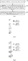
- Fig. 1 shows a DMRS pattern of a configuration type 1.
- a DMRS mapped to one OFDM symbol may support at most four antenna ports.
- One OFDM symbol may include two groups of comb resources, and each group of comb resources may correspond to one antenna port.
- Each group of comb resources may carry two groups of cyclically-shifted sequence codes, and one group of sequence codes may correspond to one antenna port.
- the DMRS mapped to one OFDM symbol may support at most four antenna ports
- the DMRS mapped to two OFDM symbols may support at most eight antenna ports.
- Fig.2 shows a DMRS pattern of a configuration type 2.
- the DMRS mapped to one OFDM symbol may support at most six antenna ports. At most three groups of DMRS patterns with consecutive REs may be mapped to one OFDM symbol, and each group of DMRS patterns may correspond to one antenna port. Each group of DMRS patterns may carry two groups of orthogonal codes, and each group of orthogonal codes may correspond to one antenna port.
- the DMRS mapped to one OFDM symbol may support at most six antenna ports, and the DMRS mapped to two OFDM symbols may support at most twelve antenna ports.
- a position of a first DMRS for the PDSCH may be fixed on a third and/or fourth OFDM symbols within a normal slot, or on an OFDM symbol for scheduling data within a first non-normal slot.
- the position of the first DMRS may be switched between the third OFDM symbol and/or fourth OFDM symbol and the first symbol for scheduling the data.
- An object of the present disclosure is to provide a DMRS transmission method, a network device and a computer-readable storage medium, so as to solve the problems in the related art where there is no DMRS configuration and transmission method in the mini-slot scenario in the NR system.
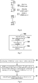
- the present disclosure provides in this embodiment a DMRS transmission method for a network device which, as shown in Fig.3 , includes Steps 31 to 33.
- Step 31 configuring a DMRS for a service channel within a mini-slot.
- a normal slot (also called as slot) has a length of 7 or 14 time-domain symbols (also called OFDM symbols).
- a slot having a length shorter than the normal slot may be called as short slot or mini-slot.
- a control channel and a service channel may occur in one or more time-domain symbols concurrently, and at this time, the network device needs to configure the DMRSs for the control channel and the service channel respectively.
- Step 32 mapping at least one antenna port corresponding to the DMRS for the service channel to a time-domain transmission resource and a frequency-domain transmission resource corresponding to a DMRS for a control channel within the mini-slot.
- the network device may map the at least one antenna port corresponding to the DMRS for the service channel to the transmission resources corresponding to the DMRS for the control channel.
- the transmission resources mainly include the time-domain transmission resource and the frequency-domain transmission resource.
- a UE may determine, through decoding, whether the DMRS transmitted on the transmission resources is for the control channel or the service channel.
- the network device may multiplex a part of the DMRS ports for the service channel to the transmission resources for the control channel, so as to improve the resource utilization of the control channel, and rapidly demodulate the service channel.
- the service channel may include a Physical Uplink Shared Channel (PUSCH) or a Physical Downlink Shared Channel (PDSCH).
- the control channel may include a Physical Uplink Control Channel (PUCCH) or a Physical Downlink Control Channel (PDCCH).
- the network device may multiplex a part of the DMRS ports for the PUSCH to the transmission resources for the PUCCH, and multiplex a part of the DMRS ports for the PDSCH to the transmission resources for the PDCCH, so as to improve the resource utilization, and rapidly demodulate the service channel.
- Step 33 transmitting or receiving the DMRS for the service channel on the time-domain transmission resource and the frequency-domain transmission resource.
- the network device may multiplex a part of the DMRS ports for the service channel to the transmission resources for the control channel. In other words, the network device may transmit the DMRS for the service channel and the DMRS for the control channel to the UE on the corresponding transmission resources, so that the UE may demodulate the service channel and the control channel in accordance with the corresponding DMRSs.
- Scenario 1 in a mini-slot transmission scenario, when the number of the antenna ports corresponding to the DMRS for the service channel is smaller than or equal to a predetermined value N, same time-frequency-domain resources may be multiplexed by the DMRS for the service channel and the DMRS for the control channel.
- Step 32 may include, when the number of the antenna ports corresponding to the DMRS for the service channel is smaller than or equal to a predetermined value, mapping all the antenna ports corresponding to the DMRS for the service channel to the time-domain transmission resource and the frequency-domain transmission resource corresponding to the DMRS for the control channel within the mini-slot.
- a part of resources of a first symbol (e.g., a low-frequency portion in figure) are occupied by the control channel, the number of the antenna ports corresponding to the DMRS for the control channel is 1, the other resources are occupied by the service channel, and the number of the antenna ports corresponding to the DMRS for the service channel is 1.
- the network device may map the DMRS for the service channel to the transmission resources corresponding to the DMRS for the control channel.
- the same time-frequency-domain resources are multiplexed by the DMRS for the service channel and the DMRS for the control channel, it is able to improve the resource utilization as well as a downlink data transmission rate.
- Scenario 2 in the mini-slot transmission scenario, the number of the antenna ports corresponding to the DMRS for the service channel is greater than the predetermined value N, same time-frequency-domain resources may be multiplexed by parts of the DMRS ports for the service channel and the DMRS for the control channel.
- Step 32 may include, when the number of the antenna ports corresponding to the DMRS for the service channel is greater than the predetermined value, mapping a first part of the antenna ports corresponding to the DMRS for the service channel to the time-domain transmission resource and the frequency-domain transmission resource corresponding to the DMRS for the control channel within the mini-slot, and mapping, to a transmission resource of M symbols being offset in time domain relative to the time-domain transmission resource corresponding to the control channel within the mini-slot, a second part of the antenna ports corresponding to the DMRS for the service channel.
- the second part of the antenna ports may be antenna ports corresponding to the DMRS for the service channel which overlap the frequency-domain transmission resource corresponding to the DMRS for the control channel, or antenna ports corresponding to the DMRS for the service channel whose number is greater than the predetermined value, or the antenna ports corresponding to the DMRS for the service channel whose number is greater than the predetermined value and which overlap the frequency-domain transmission resource corresponding to the DMRS for the control channel.
- the first part of the antenna ports is all the antenna ports corresponding to the DMRS for the service channel other than the second part of the antenna ports.
- a portion of the DMRS for the service channel overlapping the DMRS for the control channel may be offset backward by M symbols.
- a part of resources of a first symbol e.g., a low-frequency portion in figure
- the number of the antenna ports corresponding to the DMRS for the control channel is 1, the other resources are occupied by the service channel, and the number of the antenna ports corresponding to the DMRS for the service channel is 2.
- the same time-frequency-domain transmission resources are multiplexed by the DMRS for the service channel and the DMRS for the control channel in the case that the number of the antenna ports corresponding to the DMRS for the service channel is smaller than or equal to 1, it is necessary to enable the part of the antenna ports overlapping the frequency-domain resource corresponding to the DMRS for the control channel to be backward by one symbol, because the number of the antenna ports corresponding to the DMRS for the service channel is 2.
- the time-domain resource is multiplexed by the DMRS for the downlink service channel and the DMRS for the control channel and the frequency-domain resource is offset backward, it is able to improve the resource utilization as well as the downlink data transmission rate.
- the same time-frequency-domain resources may be multiplexed by the antenna ports corresponding to the DMRS for the service channel whose number is smaller than N and the DMRS for the control channel, and the other antenna ports corresponding to the DMRS for the service channel may be offset backward by M symbols.
- a part of resources of a first symbol (e.g., a low-frequency portion in the figure) are occupied by the control channel, the number of the antenna ports corresponding to the DMRS for the control channel is 1, the other resources are occupied by the service channel, and the number of the antenna ports corresponding to the DMRS for the service channel is 2.
- the same time-frequency-domain transmission resources are multiplexed by the DMRS for the service channel and the DMRS for the control channel in the case that the number of the antenna ports corresponding to the DMRS for the service channel is smaller than or equal to 1
- the same time-frequency-domain transmission resources may be multiplexed by an antenna port 1 corresponding to the DMRS for the service channel and the DMRS for the control channel, and a portion of the DMRS for the service channel corresponding to an antenna port 2 and overlapping the frequency-domain resource corresponding to the DMRS for the control channel may be offset backward by one symbol.
- each DMRS for the service channel corresponding to the antenna port 2 may be offset backward by one symbol.
- Step 31 may include: configuring predetermined parameters of the DMRS for the service channel within the mini-slot; and transmitting the predetermined parameters of the DMRS for the service channel to the UE.
- the predetermined parameters may include at least one of configuration type information, frequency-domain density information, time-domain position information, and occupied-port information.
- the configuration type information of the DMRS may be used to indicate whether the DMRS pattern is of the configuration type 1 or the configuration type 2.
- the network device may transmit the configuration type information carried in a broadcast channel or Radio Resource Control (RRC) signaling to the UE.
- RRC Radio Resource Control
- the frequency-domain density information of the DMRS may be used to indicate a frequency-domain density of the DMRS, i.e., a frequency-domain distribution of the DMRS, it mainly functions as to reduce the overhead for the DMRS.
- the network device may transmit the frequency-domain density information carried in the RRC signaling to the UE.
- the time-domain position information of the DMRS may be used to indicate a position of the time-domain symbol occupied by the DMRS.
- the network device may transmit the time-domain position information carried in the RRC signaling to the UE.
- the occupied-port information of the DMRS may be used to indicate a port or a port set occupied by the DMRS.
- the network device may transmit the occupied-port information carried in Downlink Control Information (DCI) to the UE.
- DCI Downlink Control Information
- the network device may multiplex the DMRS for the service channel to the time-frequency-domain transmission resources corresponding to the DMRS for the control channel in the mini-slot transmission scenario, so it is able for the UE to measure a data channel in advance on the transmission resources for the control channel, thereby to effectively improve the data transmission rate.
- the present disclosure further provides in the first embodiment a network device 700 capable of configuring a DMRS for a service channel within a mini-slot, mapping at least one antenna port corresponding to the DMRS for the service channel to a time-domain transmission resource and a frequency-domain transmission resource corresponding to a DMRS for a control channel within the mini-slot, and transmitting or receiving the DMRS for the service channel on the time-domain transmission resource and the frequency-domain transmission resource, with a same technical effect.
- the network device 700 may include: a first configuration module 710 configured to configure the DMRS for the service channel within the mini-slot; a first mapping module 720 configured to map at least one antenna port corresponding to the DMRS for the service channel to the time-domain transmission resource and the frequency-domain transmission resource corresponding to the DMRS for the control channel within the mini-slot; and a first transmission module 730 configured to transmit or receive the DMRS for the service channel on the time-domain transmission resource and the frequency-domain transmission resource.
- a first configuration module 710 configured to configure the DMRS for the service channel within the mini-slot
- a first mapping module 720 configured to map at least one antenna port corresponding to the DMRS for the service channel to the time-domain transmission resource and the frequency-domain transmission resource corresponding to the DMRS for the control channel within the mini-slot
- a first transmission module 730 configured to transmit or receive the DMRS for the service channel on the time-domain transmission resource and the frequency-domain transmission resource.
- the first mapping module 720 may include: a first mapping unit configured to, when the number of the antenna ports corresponding to the DMRS for the service channel is smaller than or equal to a predetermined value, map all the antenna ports corresponding to the DMRS for the service channel to the time-domain transmission resource and the frequency-domain transmission resource corresponding to the DMRS for the control channel.
- the first mapping module 720 may further include: a second mapping unit configured to, when the number of the antenna ports corresponding to the DMRS for the service channel is greater than the predetermined value, map a first part of the antenna ports corresponding to the DMRS for the service channel to the time-domain transmission resource and the frequency-domain transmission resource corresponding to the DMRS for the control channel within the mini-slot; and a third mapping unit configured to map, to a transmission resource of M symbols being offset in time domain relative to the time-domain transmission resource corresponding to the control channel within the mini-slot, a second part of the antenna ports corresponding to the DMRS for the service channel, where M is an integer greater than or equal to 1.
- the second part of the antenna ports is antenna ports corresponding to the DMRS for the service channel which overlap the frequency-domain transmission resource corresponding to the DMRS for the control channel, or antenna ports corresponding to the DMRS for the service channel whose number is greater than the predetermined value and which overlap the frequency-domain transmission resource corresponding to the DMRS for the control channel; and the first part of the antenna ports is all the antenna ports corresponding to the DMRS for the service channel other than the second part of the antenna ports.
- the first configuration module 710 may include: a first configuration unit configured to configure predetermined parameters of the DMRS for the service channel within the mini-slot; and a transmission unit configured to transmit the predetermined parameters of the DMRS for the service channel to the UE.
- the predetermined parameters may include at least one of configuration type information, frequency-domain density information, time-domain position information, and occupied-port information.
- the service channel may include a PUSCH or a PDSCH
- the control channel may include a PUCCH or a PDCCH.
- the network device may multiplex the DMRS for the service channel in the mini-slot to the time-frequency-domain transmission resources corresponding to the DMRS for the control channel in the mini-slot in the mini-slot transmission scenario, so it is able for the UE to measure a data channel in advance on the transmission resources for the control channel, thereby to effectively improve the data transmission rate.
- the present disclosure further provides in this embodiment a DMRS transmission method for a network device.
- the DMRS transmission method includes Steps 81 to 83.
- Step 81 configuring a DMRS for a service channel within a mini-slot.
- a control channel and the service channel may occur on one or more time-domain symbols concurrently, and at this time, the network device needs to configure the DMRSs for the control channel and the service channel respectively.
- Step 82 mapping, to a transmission resource of M symbols being offset in time domain relative to a time-domain transmission resource corresponding to a control channel within the mini-slot, at least one antenna port corresponding to the DMRS for the service channel.
- M may be an integer greater than or equal to 1.
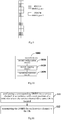
- Fig.9 where each antenna port is mapped to the transmission resource of M symbols being offset in time domain relative to the time-domain transmission resource, it is presumed that two time-domain symbols are occupied by a downlink mini-slot, a part of resources of a first symbol (e.g., a low-frequency portion in the figure) are occupied by the control channel, the number of the antenna ports corresponding to the DMRS for the control channel is 1, the other resources are occupied by the service channel, and the number of the antenna ports corresponding to the DMRS for the service channel is 1.
- a part of the DMRS for the service channel overlapping the frequency-domain resource corresponding to the DMRS for the control channel may be offset backward by one symbol.
- a part of the DMRS for the service channel overlapping the frequency-domain resource corresponding to the DMRS for the control channel is offset backward, it is able to prevent the occurrence of the interference between the DMRS for the service channel and the DMRS for the control channel, thereby to improve a downlink data transmission rate.
- the service channel may include a PUSCH or a PDSCH
- the control channel may include a PUCCH or a PDCCH.
- Step 83 transmitting the DMRS for the service channel on the transmission resource.
- the network device may multiplex a part of the antenna ports corresponding to the DMRS for the service channel not overlapping the DMRS for the control channel to the transmission resource corresponding to the DMRS for the control channel within the mini-slot, and the DMRS for the service channel overlapping the DMRS for the control channel may be offset by M time-domain symbols, i.e., the network device may transmit a part of the DMRS for the service channel through the control channel. As a result, it is able to improve the resource utilization as well as the downlink data transmission rate.
- the network device may multiplex a part of the antenna ports corresponding to the DMRS for the service channel and not overlapping the DMRS for the control channel to the transmission resource for the control channel, so as to enable the service channel and the control channel to multiplex a part of the transmission resources, thereby to improve the resource utilization.
- it is able for the UE to measure a data channel in advance on the transmission resource for the control channel, thereby to effectively improve the data transmission rate.
- the present disclosure further provides in the first embodiment a network device 1000 capable of configuring a DMRS for a service channel within a mini-slot, mapping, to a transmission resource of M symbols being offset in time domain relative to a time-domain transmission resource corresponding to a control channel within the mini-slot, at least one antenna port corresponding to the DMRS for the service channel, M being an integer greater than or equal to 1, and transmitting the DMRS for the service channel on the transmission resource, with a same technical effect.
- the network device 1000 may include: a second configuration module 1010 configured to configure the DMRS for the service channel within the mini-slot; a second mapping module 1020 configured to map, to the transmission resource of M symbols being offset in time domain relative to the time-domain transmission resource corresponding to the control channel within the mini-slot, at least one antenna port corresponding to the DMRS for the service channel, M being an integer greater than or equal to 1; and a second transmission module 1030 configured to transmit the DMRS for the service channel on the transmission resource.
- a second configuration module 1010 configured to configure the DMRS for the service channel within the mini-slot
- a second mapping module 1020 configured to map, to the transmission resource of M symbols being offset in time domain relative to the time-domain transmission resource corresponding to the control channel within the mini-slot, at least one antenna port corresponding to the DMRS for the service channel, M being an integer greater than or equal to 1
- a second transmission module 1030 configured to transmit the DMRS for the service channel on the transmission resource.
- the service channel may include a PUSCH or a PDSCH
- the control channel may include a PUCCH or a PDCCH.
- the network device may multiplex a part of the antenna ports corresponding to the DMRS for the service channel and not overlapping the DMRS for the control channel to the transmission resource for the control channel, so as to enable the service channel and the control channel to multiplex a part of the transmission resources, thereby to improve the resource utilization.
- it is able for the UE to measure a data channel in advance on the transmission resource for the control channel, thereby to effectively improve the data transmission rate.
- the present disclosure further provides in the third embodiment a DMRS transmission method for a network device.
- the DMRS transmission method includes Steps 111 and 112.
- Step 111 configuring a corresponding DMRS for a service channel in accordance with a start position of a mini-slot where the service channel for a same UE is located.
- a normal slot (also called as slot) has a length of 7 or 14 time-domain symbols (also called OFDM symbols), and a slot having a length smaller than the normal slot may be called as short slot or mini-slot.
- the network device may concurrently configure slot-based transmission and mini-slot-based transmission for the same UE. At this time, it is necessary to configure the corresponding DMRS in accordance with the start transmission position of the mini-slot.
- Step 112 transmitting the DMRS for each service channel to the UE.
- the network device may transmit the DMRS to the UE on the corresponding transmission resource, so that the UE may demodulate the service channel in accordance with the corresponding DMRS.
- Step 111 may include: when a first time-domain symbol of the mini-slot, where the service channel for the same UE is located, is located before a first time-domain symbol of a front-loaded DMRS within a normal slot, separately configuring the DMRS within the mini-slot where the service channel is located, and the front-loaded DMRS and/or an additional DMRS within the normal slot.
- the network device may configure a separate DMRS for the service channel within the mini-slot, and further configure the front-loaded DMRS and the additional DMRS within the slot.
- Step 111 may further include, when the first time-domain symbol of the mini-slot where the service channel for the same UE is located is located on a time-domain symbol of the front-loaded DMRS or the additional DMRS within the normal slot, separately configuring the DMRS within the mini-slot where the service channel is located, and the front-loaded DMRS and/or the additional DMRS within the normal slot.
- a service transmitted within the mini-slot has a relatively higher priority level, so it is still necessary for the network device to separately configure the DMRS within the mini-slot, although the front-loaded DMRS and/or the additional DMRS within the slot have been configured by the network device.
- Step 111 may further include, when the first time-domain symbol of the mini-slot where the service channel for the same UE is located is located on a time-domain symbol of the front-loaded DMRS or the additional DMRS within the normal slot, not configuring the configuration of the front-loaded DMRS or the additional DMRS within the normal slot, and configuring the DMRS within the mini-slot where the service channel is located.
- the configuration of the front-loaded DMRS or the additional DMRS within the slot may be not configured and the DMRS within the mini-slot may be configured, so as to prevent the interference caused by the front-loaded DMRS or the additional DMRS within the slot on the DMRS within the mini-slot.
- Step 111 may further include, when the first time-domain symbol of the mini-slot where the service channel for the same UE is located is located on a time-domain symbol of the front-loaded DMRS or the additional DMRS within the normal slot, configuring the front-loaded DMRS and/or the additional DMRS within the normal slot, and determining the front-loaded DMRS and/or the additional DMRS as the DMRS within the mini-slot where the service channel is located.
- the front-loaded DMRS and/or the additional DMRS may be directly determined as the DMRS within the mini-slot, so as to reduce the transmission resources.
- Step 111 may further include, when the first time-domain symbol of the mini-slot where the service channel for the same UE is located is located after the time-domain symbol of the front-loaded DMRS and/or the additional DMRS within the normal slot, separately configuring the DMRS within the mini-slot where the service channel is located, and the front-loaded DMRS and/or the additional DMRS within the normal slot.
- the first symbol of the mini-slot is located after the time-domain symbol of the front-loaded DMRS and/or the additional DMRS within the slot, it is still necessary to separately configure the DMRS within the mini-slot, although the network device has configured the front-loaded DMRS and/or the additional DMRS within the slot.
- Step 111 may further include, when the first time-domain symbol of the mini-slot where the service channel for the same UE is located is located after the time-domain symbol of the front-loaded DMRS and/or the additional DMRS within the normal slot, configuring the front-loaded DMRS and/or the additional DMRS within the normal slot, and determining the front-loaded DMRS and/or the additional DMRS as the DMRS within the mini-slot where the service channel is located.
- the front-loaded DMRS and/or the additional DMRS may be directly determined as the DMRS within the mini-slot, so as to reduce the transmission resources.
- the network device may configure the corresponding DMRS at the start position of the mini-slot. Different DMRSs may be configured depending on different start positions of the mini-slot. This configuration mode is flexible, so it is able to flexibly configure the resources while ensuring the accurate demodulation of the channel and the normal data transmission, thereby to maximize the resource utilization.
- the present disclosure further provides in the embodiment a network device 1200 capable of configuring a corresponding DMRS for a service channel in accordance with a start position of a mini-slot where the service channel for a same UE is located, and transmit the DMRS for the service cannel to the UE, with a same technical effect.
- the network device 1200 may include: a third configuration module 1210 configured to configure the corresponding DMRS for the service channel in accordance with the start position of the mini-slot where the service channel for the same UE is located; and a third transmission module 1220 configured to transmit the DMRS for the service channel to the UE.
- the third configuration module 1210 may include: a first configuration sub-module configured to, when a first time-domain symbol of the mini-slot where the service channel for the same UE is located is located before a first time-domain symbol of a front-loaded DMRS within a normal slot, separately configure the DMRS within the mini-slot where the service channel is located, and the front-loaded DMRS and/or an additional DMRS within the normal slot.
- the third configuration module 1210 may include: a second configuration sub-module configured to, when the first time-domain symbol of the mini-slot where the service channel for the same UE is located is located on a time-domain symbol of the front-loaded DMRS or the additional DMRS within the normal slot, separately configure the DMRS within the mini-slot where the service channel is located, and the front-loaded DMRS and/or the additional DMRS within the normal slot; or a third configuration sub-module configured to, when the first time-domain symbol of the mini-slot where the service channel for the same UE is located is located on a time-domain symbol of the front-loaded DMRS or the additional DMRS within the normal slot, not configure the configuration of the front-loaded DMRS or the additional DMRS within the normal slot, and configure the DMRS within the mini-slot where the service channel is located; or a fourth configuration sub-module configured to, when the first time-domain symbol of the mini-slot where the service channel for the same UE is located
- the third configuration module 1210 may further include: a fifth configuration sub-module configured to, when the first time-domain symbol of the mini-slot where the service channel for the same UE is located is located after the time-domain symbol of the front-loaded DMRS and/or the additional DMRS within the normal slot, separately configure the DMRS within the mini-slot where the service channel is located, and the front-loaded DMRS and/or the additional DMRS within the normal slot; or a sixth configuration sub-module configured to, when the first time-domain symbol of the mini-slot where the service channel for the same UE is located is located after the time-domain symbol of the front-loaded DMRS and/or the additional DMRS within the normal slot, configure the front-loaded DMRS and/or the additional DMRS within the normal slot, and determine the front-loaded DMRS and/or the additional DMRS as the DMRS within the mini-slot where the service channel is located.
- a fifth configuration sub-module configured to, when the first time-domain
- the network device may configure the corresponding DMRS at the start position of the mini-slot. Different DMRSs may be configured depending on different start positions of the mini-slot. This configuration mode is flexible, so it is able to flexibly configure the resources while ensuring the accurate demodulation of the channel and the normal data transmission, thereby to maximize the resource utilization.
- the present disclosure further provides in some embodiments a network device which includes a processor, a memory, and a program being stored in the memory and capable of being executed by the processor.
- the processor is configured to execute the program so as to implement the above-mentioned DMRS transmission method.
- the present disclosure further provides in some embodiments a computer-readable storage medium storing therein a program. The program is executed by a processor so as to implement the above-mentioned DMRS transmission method.
- the present disclosure further provides in some embodiments a network device 1300 which, as shown in Fig.13 , includes an antenna 131, a Radio Frequency (RF) device 132, and a baseband device 133.
- the antenna 131 is connected to the RF device 132.
- the RF device 132 is configured to receive information via the antenna 131, and transmit the received information to the baseband device 133 for processing.
- the baseband device 133 is configured to process to-be-transmitted information, and transmit the processed information to the RF device 132.
- the RF device 132 is configured to process the received information and transmit the processed information via the antenna 131.
- a frequency band processing unit may be located within the baseband device 133, so that the above method for the network device of the above embodiment may be implemented within the baseband device 133.
- the baseband device 133 may include a processor 134 and a memory 135.
- the baseband device 133 may, e.g., include at least one baseband board on which a plurality of chips is located, as shown in Fig. 13 .
- One chip may be, e.g., the processor 134 connected to the memory 135 and configured to call a program stored in the memory 135 so as to perform operations for the network device in the above-mentioned method embodiments.
- the baseband device 133 may further include a network interface 136 configured to exchange information with the RF device 132.
- the network interface may be, e.g., a Common Public Radio Interface (CPRI).
- CPRI Common Public Radio Interface
- the processor may include merely one processor, or a plurality of processing elements.
- the processor may be a Central Processing Unit (CPU), an Application Specific Integrated Circuit (ASIC), or one or more Integrated Circuits (ICs) configured to implement the above-mentioned method for the network device, e.g., one or more Digital Signal Processors (DSPs), or one or more Field Programmable Gate Arrays (FPGAs).
- the memory may include merely one memory, or a plurality of storage elements.
- the memory 135 may be a volatile memory, a nonvolatile memory or both.
- the nonvolatile memory may be a Read-Only Memory (ROM), a Programmable ROM (PROM), an Erasable PROM (EPROM), an Electrically EPROM (EEPROM) or a flash memory.
- the volatile memory may be a Random Access Memory (RAM) which serves as an external high-speed cache.
- the RAM may be in various forms, e.g., Static RAM (SRAM), Dynamic RAM (DRAM), Synchronous DRAM (SDRAM), Double Data Rate SDRAM (DDRSDRAM), Enhanced SDRAM (ESDRAM), Synchlink DRAM (SLDRAM) or Direct Rambus RAM (DRRAM).
- the memory 135 intends to include, but not limited to, the above-mentioned and any other appropriate memories.
- the network device may further include a computer program stored in the memory 135 and executed by the processor 134.
- the processor 134 is configured to call the computer program in the memory 135 so as to implement the method executed by the modules in Fig.7 .
- the processor 134 is configured to call the computer program, so as to: configure a DMRS for a service channel within a mini-slot; map at least one antenna port corresponding to the DMRS for the service channel to a time-domain transmission resource and a frequency-domain transmission resource corresponding to a DMRS for a control channel within the mini-slot; and transmit or receive the DMRS for the service channel on the time-domain transmission resource and the frequency-domain transmission resource.
- the processor 134 is configured to call the computer program, so as to, when the number of the antenna ports corresponding to the DMRS for the service channel is smaller than or equal to a predetermined value, map all the antenna ports corresponding to the DMRS for the service channel to the time-domain transmission resource and the frequency-domain transmission resource corresponding to the DMRS for the control channel within the mini-slot.
- the processor 134 is configured to call the computer program, so as to: when the number of the antenna ports corresponding to the DMRS for the service channel is greater than the predetermined value, map a first part of the antenna ports corresponding to the DMRS for the service channel to the time-domain transmission resource and the frequency-domain transmission resource corresponding to the DMRS for the control channel within the mini-slot; and map, to a transmission resource of M symbols being offset in time domain relative to the time-domain transmission resource corresponding to the control channel within the mini-slot, a second part of the antenna ports corresponding to the DMRS for the service channel, where M is an integer greater than or equal to 1.
- the second part of the antenna ports may include antenna ports corresponding to the DMRS for the service channel and overlapping the frequency-domain transmission resource corresponding to the DMRS for the control channel, or antenna ports corresponding to the DMRS for the service channel whose number is greater than the predetermined value.
- the first part of the antenna ports may include all the antenna ports corresponding to the DMRS for the service channel other than the second part of the antenna ports.
- the processor 134 is configured to call the computer program, so as to: configure predetermined parameters of the DMRS for the service channel within the mini-slot; and transmit the predetermined parameters of the DMRS for the service channel to the UE.
- the predetermined parameters may include at least one of configuration type information, frequency-domain density information, time-domain position information, and occupied-port information.
- the service channel may include a PUSCH or a PDSCH
- the control channel may include a PUCCH or a PDCCH.
- the network device may multiplex the DMRS for the service channel to the time-frequency-domain transmission resources corresponding to the DMRS for the control channel in the mini-slot transmission scenario, so it is able for the UE to measure a data channel in advance on the transmission resources for the control channel, thereby to effectively improve the data transmission rate.
- the processor 134 is further configured to call the computer program stored in the memory 135, so as to implement the method executed by the modules in Fig. 10 .
- the processor 134 is configured to call the computer program, so as to: configure a DMRS for a service channel within a mini-slot; map, to a transmission resource of M symbols being offset in time domain relative to a time-domain transmission resource corresponding to a control channel within the mini-slot, at least one antenna port corresponding to the DMRS for the service channel, M being an integer greater than or equal to 1; and transmit the DMRS for the service channel on the transmission resource.
- the service channel may include a PUSCH or a PDSCH
- the control channel may include a PUCCH or a PDCCH.
- the network device may multiplex a part of the antenna ports corresponding to the DMRS for the service channel and not overlapping the DMRS for the control channel to the transmission resource for the control channel, so as to enable the service channel and the control channel to multiplex a part of the transmission resources, thereby to improve the resource utilization.
- it is able for the UE to measure a data channel in advance on the transmission resource for the control channel, thereby to effectively improve the data transmission rate.
- the processor 134 is further configured to call the computer program stored in the memory 135, so as to implement the method executed by the modules in Fig.12 .
- the processor 134 is configured to call the computer program, so as to: configure a corresponding DMRS for a service channel in accordance with a start position of a mini-slot where the service channel for a same UE is located; and transmit the DMRS for the service channel to the UE.
- the processor 134 is configured to call the computer program, so as to, when a first time-domain symbol of the mini-slot where the service channel for the same UE is located is located before a first time-domain symbol of a front-loaded DMRS within a normal slot, separately configure the DMRS within the mini-slot where the service channel is located, and the front-loaded DMRS and/or an additional DMRS within the normal slot.
- the processor 134 is configured to call the computer program, so as to: when the first time-domain symbol of the mini-slot where the service channel for the same UE is located is located on a time-domain symbol of the front-loaded DMRS or the additional DMRS within the normal slot, separately configure the DMRS within the mini-slot where the service channel is located, and the front-loaded DMRS and/or the additional DMRS within the normal slot; or when the first time-domain symbol of the mini-slot where the service channel for the same UE is located is located on a time-domain symbol of the front-loaded DMRS or the additional DMRS within the normal slot, not configure the configuration of the front-loaded DMRS or the additional DMRS within the normal slot, and configure the DMRS within the mini-slot where the service channel is located; or when the first time-domain symbol of the mini-slot where the service channel for the same UE is located is located on a time-domain symbol of the front-loaded DMRS or the additional DMRS within the normal
- the processor 134 is configured to call the computer program, so as to: when the first time-domain symbol of the mini-slot where the service channel for the same UE is located is located after the time-domain symbol of the front-loaded DMRS and/or the additional DMRS within the normal slot, separately configure the DMRS within the mini-slot where the service channel is located, and the front-loaded DMRS and/or the additional DMRS within the normal slot; or when the first time-domain symbol of the mini-slot where the service channel for the same UE is located is located after the time-domain symbol of the front-loaded DMRS and/or the additional DMRS within the normal slot, configure the front-loaded DMRS and/or the additional DMRS within the normal slot, and determine the front-loaded DMRS and/or the additional DMRS as the DMRS within the mini-slot where the service channel is located.
- the network device may be a Base Transceiver Station (BTS) in a Global System of Mobile communication (GSM) system or a Code Division Multiple Access (CDMA) system, a Node B (NB) in a Wideband Code Division Multiple Access (WCDMA) system, an evolved Node B (eNB, or eNodeB), a relay or an access point in a Long Term Evolution (LTE) system, or a base station in a coming 5G network, which will not be particularly defined herein.
- BTS Base Transceiver Station
- GSM Global System of Mobile communication
- CDMA Code Division Multiple Access
- NB Node B
- WCDMA Wideband Code Division Multiple Access
- eNB evolved Node B
- LTE Long Term Evolution
- the network device may configure the corresponding DMRS at the start position of the mini-slot. Different DMRSs may be configured depending on different start positions of the mini-slot. This configuration mode is flexible, so it is able to flexibly configure the resources while ensuring the accurate demodulation of the channel and the normal data transmission, thereby to maximize the resource utilization.
- the device and method may be implemented in any other ways.
- the embodiments for the device is merely for illustrative purposes, and the units are provided merely on the basis of their logic functions.
- the units may be provided in other manners, for example, some components or units may be combined together or integrated into another system. Alternatively, some functions of the components or units may be omitted or not executed.
- the coupling connection, direct coupling connection or communication connection between the components or units may be implemented via interfaces, and the indirect coupling connection or communication connection between the devices or units may be implemented in an electrical or mechanical form or in any other form.
- the units may be, or may not be, physically separated from each other.
- the shown units may be, or may not be, physical units, i.e., they may be arranged at an identical position, or distributed on a plurality of network elements. Parts or all of the units may be selected in accordance with the practical need, so as to achieve the purpose of the present disclosure.
- the functional units in the embodiments of the present disclosure may be integrated into a processing unit, or the functional units may exist independently, or two or more functional units may be combined together.
- the functional units are implemented in a software form and sold or used as a separate product, they may be stored in a computer-readable medium.
- the technical solutions of the present disclosure partial or full, parts of the technical solutions of the present disclosure contributing to the related art, or parts of the technical solutions may appear in the form of software products, which may be stored in a storage medium and include instructions so as to enable computer equipment (e.g., a personal computer, a server or network equipment) to execute all or parts of the steps of the method according to the embodiments of the present disclosure.
- computer equipment e.g., a personal computer, a server or network equipment
- the storage medium includes any medium capable of storing therein program codes, e.g., a Universal Serial Bus (USB) flash disk, a mobile Hard Disk (HD), a Read-Only Memory (ROM), a Random Access Memory (RAM), a magnetic disk or an optical disk.
- USB Universal Serial Bus
- HD Hard Disk
- ROM Read-Only Memory
- RAM Random Access Memory
- the members and/or steps may be subdivided and/or recombined, which shall also be deemed as equivalents of the present disclosure.
- the steps for executing the above-mentioned processings may be performed in a chronological order, but the present disclosure is not limited thereto. Some steps may also be performed in parallel, or independently of each other.
- the purposes of the present disclosure may also be implemented by one program or a set of programs running on any computing device, e.g., a known general-purpose device, or implemented merely by a program product including programs codes capable of implementing the method or device.
- this program product and a storage medium storing therein the program product also constitute a part of the present disclosure.
- the storage medium may be any known storage medium or a storage medium that may be developed in future.
- the members and/or steps may be subdivided and/or recombined, which shall also be deemed as equivalents of the present disclosure.
- the steps for executing the above-mentioned processings may be performed in a chronological order, but the present disclosure is not limited thereto. Some steps may also be performed in parallel, or independently of each other.
Landscapes
- Engineering & Computer Science (AREA)
- Signal Processing (AREA)
- Computer Networks & Wireless Communication (AREA)
- Mobile Radio Communication Systems (AREA)
- Transceivers (AREA)
Applications Claiming Priority (2)
| Application Number | Priority Date | Filing Date | Title |
|---|---|---|---|
| CN201710657551.9A CN109391387B (zh) | 2017-08-03 | 2017-08-03 | 解调参考信号传输方法、网络设备及计算机可读存储介质 |
| PCT/CN2018/096804 WO2019024711A1 (zh) | 2017-08-03 | 2018-07-24 | 解调参考信号传输方法、网络设备及计算机可读存储介质 |
Publications (3)
| Publication Number | Publication Date |
|---|---|
| EP3664555A1 true EP3664555A1 (de) | 2020-06-10 |
| EP3664555A4 EP3664555A4 (de) | 2020-08-12 |
| EP3664555B1 EP3664555B1 (de) | 2023-11-22 |
Family
ID=65233529
Family Applications (1)
| Application Number | Title | Priority Date | Filing Date |
|---|---|---|---|
| EP18840905.6A Active EP3664555B1 (de) | 2017-08-03 | 2018-07-24 | Verfahren zur übertragung eines demodulationsreferenzsignals, netzwerkvorrichtung und computerlesbares speichermedium |
Country Status (5)
| Country | Link |
|---|---|
| US (1) | US11476991B2 (de) |
| EP (1) | EP3664555B1 (de) |
| CN (2) | CN109391387B (de) |
| ES (1) | ES2966621T3 (de) |
| WO (1) | WO2019024711A1 (de) |
Cited By (2)
| Publication number | Priority date | Publication date | Assignee | Title |
|---|---|---|---|---|
| EP3697011A4 (de) * | 2017-10-11 | 2020-11-25 | Vivo Mobile Communication Co., Ltd. | Verfahren zur übertragung von demodulatiosreferenzsignalen, netzvorrichtung und endgerät |
| EP4181545A4 (de) * | 2020-07-15 | 2023-12-20 | Huawei Technologies Co., Ltd. | Datenübertragungsverfahren und -vorrichtung |
Families Citing this family (18)
| Publication number | Priority date | Publication date | Assignee | Title |
|---|---|---|---|---|
| US10616914B2 (en) * | 2017-01-06 | 2020-04-07 | Qualcomm Incorporated | Unicast data transmission on a downlink common burst of a slot using mini-slots |
| JP7142148B2 (ja) | 2018-08-08 | 2022-09-26 | アイディーエーシー ホールディングス インコーポレイテッド | ニューラジオ(nr)における物理サイドリンク制御チャネル(pscch)設計に対する方法および装置 |
| WO2020226396A1 (ko) * | 2019-05-03 | 2020-11-12 | 엘지전자 주식회사 | 무선 통신 시스템에서 신호를 송수신 하는 방법 및 이를 지원하는 장치 |
| CN111836377B (zh) * | 2019-08-12 | 2023-09-22 | 维沃移动通信有限公司 | 一种调度方法、网络设备及终端 |
| CN114303429B (zh) * | 2019-11-08 | 2025-07-04 | Oppo广东移动通信有限公司 | 时域资源配置方法、装置、电子设备及存储介质 |
| CN112929967B (zh) * | 2019-12-06 | 2023-04-07 | 中国电信股份有限公司 | 网络设备及其通信方法 |
| CN116567714A (zh) * | 2020-02-17 | 2023-08-08 | 华为技术有限公司 | 一种业务传输方法及装置 |
| CN111669263B (zh) * | 2020-05-19 | 2023-04-18 | 上海芯袖微电子科技有限公司 | 5g通信中dmrs配置方法、装置和终端 |
| WO2022031617A1 (en) * | 2020-08-06 | 2022-02-10 | Intel Corporation | Dmrs indication in special slots for unpaired spectrum operations |
| CN114080031B (zh) | 2020-08-13 | 2025-08-05 | 华为技术有限公司 | 一种通信方法及装置 |
| WO2022052073A1 (zh) * | 2020-09-11 | 2022-03-17 | 北京小米移动软件有限公司 | 信道估计的方法、装置、通信设备及存储介质 |
| CN114337955A (zh) * | 2020-09-30 | 2022-04-12 | 维沃移动通信有限公司 | 传输方法、装置、设备及可读存储介质 |
| EP4231718A4 (de) | 2020-10-14 | 2023-12-06 | Beijing Xiaomi Mobile Software Co., Ltd. | Pdcch-sendeverfahren und -vorrichtung sowie pdcch-empfangsverfahren und -vorrichtung |
| CN114826505B (zh) * | 2021-01-18 | 2023-11-21 | 大唐移动通信设备有限公司 | 信息传输方法、终端设备及网络设备 |
| US12224884B2 (en) * | 2022-04-04 | 2025-02-11 | Charter Communications Operating, Llc | DMRS-free operation of new radio (NR) shared channels |
| CN117320159A (zh) * | 2022-06-21 | 2023-12-29 | 维沃移动通信有限公司 | 传输方法、设备及可读存储介质 |
| WO2024007136A1 (zh) * | 2022-07-04 | 2024-01-11 | Oppo广东移动通信有限公司 | 无线通信方法、终端设备以及网络设备 |
| WO2025166711A1 (zh) * | 2024-02-08 | 2025-08-14 | Oppo广东移动通信有限公司 | 无线通信方法、终端设备以及网络设备 |
Family Cites Families (15)
| Publication number | Priority date | Publication date | Assignee | Title |
|---|---|---|---|---|
| CN102088434B (zh) * | 2009-12-04 | 2015-05-13 | 中兴通讯股份有限公司 | 解调参考信号发送方法、序列生成方法及发射、接收装置 |
| US20130064216A1 (en) * | 2011-09-12 | 2013-03-14 | Research In Motion Limited | DMRS Association and Signaling for Enhanced PDCCH in LTE Systems |
| WO2013109036A1 (ko) * | 2012-01-16 | 2013-07-25 | 엘지전자 주식회사 | 무선 통신 시스템에서 복조참조신호 전송 방법 및 장치 |
| CN103581094B (zh) * | 2012-07-24 | 2016-12-28 | 电信科学技术研究院 | 下行用户专用解调参考信号的传输方法和设备 |
| CN103095637A (zh) * | 2012-12-18 | 2013-05-08 | 李文龙 | 一种解调参考信号传输的方法和系统 |
| CN105025574B (zh) * | 2014-04-16 | 2019-07-02 | 中兴通讯股份有限公司 | 一种数据传输方法及装置 |
| WO2016195411A1 (ko) * | 2015-06-03 | 2016-12-08 | 엘지전자 주식회사 | 무선 통신 시스템에서 v2v 통신을 위한 참조 신호 설정 방법 및 이를 위한 장치 |
| WO2017015813A1 (zh) * | 2015-07-27 | 2017-02-02 | 华为技术有限公司 | 通信方法和网络设备 |
| CN110557237B (zh) * | 2015-11-25 | 2021-10-29 | 上海朗帛通信技术有限公司 | 一种降低网络延迟的无线通信方法和装置 |
| US10313168B2 (en) * | 2015-12-11 | 2019-06-04 | Lg Electronics Inc. | Method and user equipment for receiving downlink channel, and method and base station for transmitting downlink channel |
| WO2017110959A1 (ja) * | 2015-12-25 | 2017-06-29 | 株式会社Nttドコモ | ユーザ端末、無線基地局及び無線通信方法 |
| CN106604405B (zh) | 2016-04-28 | 2021-11-19 | 纵横非凡(北京)科技有限公司 | 一种宽带集群无线传输方法与系统 |
| US10225826B2 (en) * | 2017-03-24 | 2019-03-05 | Nokia Technologies Oy | Transmission of uplink control information for multiple control channel format lengths |
| KR102318438B1 (ko) * | 2017-04-26 | 2021-10-27 | 삼성전자 주식회사 | 무선 셀룰라 통신 시스템에서 dmrs 위치 설정 방법 및 장치 |
| EP3646547A4 (de) * | 2017-06-26 | 2021-02-17 | Motorola Mobility LLC | Konfiguration eines demodulationsreferenzsignals |
-
2017
- 2017-08-03 CN CN201710657551.9A patent/CN109391387B/zh active Active
- 2017-08-03 CN CN202210122034.2A patent/CN114422098B/zh active Active
-
2018
- 2018-07-24 EP EP18840905.6A patent/EP3664555B1/de active Active
- 2018-07-24 ES ES18840905T patent/ES2966621T3/es active Active
- 2018-07-24 WO PCT/CN2018/096804 patent/WO2019024711A1/zh not_active Ceased
- 2018-07-24 US US16/635,109 patent/US11476991B2/en active Active
Cited By (4)
| Publication number | Priority date | Publication date | Assignee | Title |
|---|---|---|---|---|
| EP3697011A4 (de) * | 2017-10-11 | 2020-11-25 | Vivo Mobile Communication Co., Ltd. | Verfahren zur übertragung von demodulatiosreferenzsignalen, netzvorrichtung und endgerät |
| US11411698B2 (en) | 2017-10-11 | 2022-08-09 | Vivo Mobile Communication Co., Ltd. | Demodulation Reference Signal transmission method, network device and User Equipment |
| EP4181545A4 (de) * | 2020-07-15 | 2023-12-20 | Huawei Technologies Co., Ltd. | Datenübertragungsverfahren und -vorrichtung |
| US12538276B2 (en) | 2020-07-15 | 2026-01-27 | Huawei Technologies Co., Ltd. | Data transmission method and apparatus |
Also Published As
| Publication number | Publication date |
|---|---|
| CN109391387A (zh) | 2019-02-26 |
| WO2019024711A1 (zh) | 2019-02-07 |
| CN114422098A (zh) | 2022-04-29 |
| US11476991B2 (en) | 2022-10-18 |
| US20200220702A1 (en) | 2020-07-09 |
| EP3664555A4 (de) | 2020-08-12 |
| ES2966621T3 (es) | 2024-04-23 |
| EP3664555B1 (de) | 2023-11-22 |
| CN114422098B (zh) | 2024-07-26 |
| CN109391387B (zh) | 2022-05-17 |
Similar Documents
| Publication | Publication Date | Title |
|---|---|---|
| US11476991B2 (en) | Demodulation reference signal transmission method, network device and computer-readable storage medium | |
| US11476993B2 (en) | Method for transmitting demodulation reference signal and network device | |
| US10952207B2 (en) | Method for transmitting data, terminal device and network device | |
| US11641653B2 (en) | Method of configuring control resource set, network equipment and terminal | |
| US20200374097A1 (en) | Pilot signal generation method and apparatus | |
| EP3817479A1 (de) | Kommunikationsverfahren und kommunikationsvorrichtung | |
| US11632207B2 (en) | Method and apparatus for transmitting uplink signal | |
| JP2020500475A (ja) | 無線通信方法及び機器 | |
| US11202294B2 (en) | Methods and devices for determining downlink resource set and sending resource position information | |
| KR20210151233A (ko) | 데이터 전송 방법, 단말기 디바이스 및 네트워크 디바이스 | |
| EP3857775B1 (de) | Burst-detektion in der drahtlosen kommunikation | |
| WO2022077524A1 (en) | Dedicated resource configuration for transmission of demodulation reference signal | |
| HK40003493B (zh) | 用於传输上行信号的方法和装置 |
Legal Events
| Date | Code | Title | Description |
|---|---|---|---|
| STAA | Information on the status of an ep patent application or granted ep patent |
Free format text: STATUS: THE INTERNATIONAL PUBLICATION HAS BEEN MADE |
|
| PUAI | Public reference made under article 153(3) epc to a published international application that has entered the european phase |
Free format text: ORIGINAL CODE: 0009012 |
|
| STAA | Information on the status of an ep patent application or granted ep patent |
Free format text: STATUS: REQUEST FOR EXAMINATION WAS MADE |
|
| 17P | Request for examination filed |
Effective date: 20200226 |
|
| AK | Designated contracting states |
Kind code of ref document: A1 Designated state(s): AL AT BE BG CH CY CZ DE DK EE ES FI FR GB GR HR HU IE IS IT LI LT LU LV MC MK MT NL NO PL PT RO RS SE SI SK SM TR |
|
| AX | Request for extension of the european patent |
Extension state: BA ME |
|
| A4 | Supplementary search report drawn up and despatched |
Effective date: 20200709 |
|
| RIC1 | Information provided on ipc code assigned before grant |
Ipc: H04L 5/00 20060101ALI20200704BHEP Ipc: H04W 72/12 20090101AFI20200704BHEP |
|
| DAV | Request for validation of the european patent (deleted) | ||
| DAX | Request for extension of the european patent (deleted) | ||
| STAA | Information on the status of an ep patent application or granted ep patent |
Free format text: STATUS: EXAMINATION IS IN PROGRESS |
|
| 17Q | First examination report despatched |
Effective date: 20220405 |
|
| REG | Reference to a national code |
Ref legal event code: R079 Ipc: H04B0007060000 Ref country code: DE Ref document number: 602018061572 Country of ref document: DE Free format text: PREVIOUS MAIN CLASS: H04W0072120000 |
|
| GRAP | Despatch of communication of intention to grant a patent |
Free format text: ORIGINAL CODE: EPIDOSNIGR1 |
|
| STAA | Information on the status of an ep patent application or granted ep patent |
Free format text: STATUS: GRANT OF PATENT IS INTENDED |
|
| RIC1 | Information provided on ipc code assigned before grant |
Ipc: H04L 5/00 20060101ALI20230825BHEP Ipc: H04W 72/12 20090101ALI20230825BHEP Ipc: H04B 7/06 20060101AFI20230825BHEP |
|
| INTG | Intention to grant announced |
Effective date: 20230912 |
|
| GRAS | Grant fee paid |
Free format text: ORIGINAL CODE: EPIDOSNIGR3 |
|
| GRAA | (expected) grant |
Free format text: ORIGINAL CODE: 0009210 |
|
| STAA | Information on the status of an ep patent application or granted ep patent |
Free format text: STATUS: THE PATENT HAS BEEN GRANTED |
|
| AK | Designated contracting states |
Kind code of ref document: B1 Designated state(s): AL AT BE BG CH CY CZ DE DK EE ES FI FR GB GR HR HU IE IS IT LI LT LU LV MC MK MT NL NO PL PT RO RS SE SI SK SM TR |
|
| REG | Reference to a national code |
Ref country code: GB Ref legal event code: FG4D |
|
| REG | Reference to a national code |
Ref country code: CH Ref legal event code: EP |
|
| REG | Reference to a national code |
Ref country code: DE Ref legal event code: R096 Ref document number: 602018061572 Country of ref document: DE |
|
| REG | Reference to a national code |
Ref country code: IE Ref legal event code: FG4D |
|
| REG | Reference to a national code |
Ref country code: NL Ref legal event code: FP |
|
| REG | Reference to a national code |
Ref country code: LT Ref legal event code: MG9D |
|
| PG25 | Lapsed in a contracting state [announced via postgrant information from national office to epo] |
Ref country code: GR Free format text: LAPSE BECAUSE OF FAILURE TO SUBMIT A TRANSLATION OF THE DESCRIPTION OR TO PAY THE FEE WITHIN THE PRESCRIBED TIME-LIMIT Effective date: 20240223 |
|
| PG25 | Lapsed in a contracting state [announced via postgrant information from national office to epo] |
Ref country code: IS Free format text: LAPSE BECAUSE OF FAILURE TO SUBMIT A TRANSLATION OF THE DESCRIPTION OR TO PAY THE FEE WITHIN THE PRESCRIBED TIME-LIMIT Effective date: 20240322 |
|
| PG25 | Lapsed in a contracting state [announced via postgrant information from national office to epo] |
Ref country code: LT Free format text: LAPSE BECAUSE OF FAILURE TO SUBMIT A TRANSLATION OF THE DESCRIPTION OR TO PAY THE FEE WITHIN THE PRESCRIBED TIME-LIMIT Effective date: 20231122 |
|
| REG | Reference to a national code |
Ref country code: AT Ref legal event code: MK05 Ref document number: 1634814 Country of ref document: AT Kind code of ref document: T Effective date: 20231122 |
|
| PG25 | Lapsed in a contracting state [announced via postgrant information from national office to epo] |
Ref country code: AT Free format text: LAPSE BECAUSE OF FAILURE TO SUBMIT A TRANSLATION OF THE DESCRIPTION OR TO PAY THE FEE WITHIN THE PRESCRIBED TIME-LIMIT Effective date: 20231122 |
|
| REG | Reference to a national code |
Ref country code: ES Ref legal event code: FG2A Ref document number: 2966621 Country of ref document: ES Kind code of ref document: T3 Effective date: 20240423 |
|
| PG25 | Lapsed in a contracting state [announced via postgrant information from national office to epo] |
Ref country code: LT Free format text: LAPSE BECAUSE OF FAILURE TO SUBMIT A TRANSLATION OF THE DESCRIPTION OR TO PAY THE FEE WITHIN THE PRESCRIBED TIME-LIMIT Effective date: 20231122 Ref country code: IS Free format text: LAPSE BECAUSE OF FAILURE TO SUBMIT A TRANSLATION OF THE DESCRIPTION OR TO PAY THE FEE WITHIN THE PRESCRIBED TIME-LIMIT Effective date: 20240322 Ref country code: GR Free format text: LAPSE BECAUSE OF FAILURE TO SUBMIT A TRANSLATION OF THE DESCRIPTION OR TO PAY THE FEE WITHIN THE PRESCRIBED TIME-LIMIT Effective date: 20240223 Ref country code: BG Free format text: LAPSE BECAUSE OF FAILURE TO SUBMIT A TRANSLATION OF THE DESCRIPTION OR TO PAY THE FEE WITHIN THE PRESCRIBED TIME-LIMIT Effective date: 20240222 Ref country code: AT Free format text: LAPSE BECAUSE OF FAILURE TO SUBMIT A TRANSLATION OF THE DESCRIPTION OR TO PAY THE FEE WITHIN THE PRESCRIBED TIME-LIMIT Effective date: 20231122 Ref country code: PT Free format text: LAPSE BECAUSE OF FAILURE TO SUBMIT A TRANSLATION OF THE DESCRIPTION OR TO PAY THE FEE WITHIN THE PRESCRIBED TIME-LIMIT Effective date: 20240322 |
|
| PG25 | Lapsed in a contracting state [announced via postgrant information from national office to epo] |
Ref country code: SE Free format text: LAPSE BECAUSE OF FAILURE TO SUBMIT A TRANSLATION OF THE DESCRIPTION OR TO PAY THE FEE WITHIN THE PRESCRIBED TIME-LIMIT Effective date: 20231122 Ref country code: RS Free format text: LAPSE BECAUSE OF FAILURE TO SUBMIT A TRANSLATION OF THE DESCRIPTION OR TO PAY THE FEE WITHIN THE PRESCRIBED TIME-LIMIT Effective date: 20231122 Ref country code: PL Free format text: LAPSE BECAUSE OF FAILURE TO SUBMIT A TRANSLATION OF THE DESCRIPTION OR TO PAY THE FEE WITHIN THE PRESCRIBED TIME-LIMIT Effective date: 20231122 Ref country code: NO Free format text: LAPSE BECAUSE OF FAILURE TO SUBMIT A TRANSLATION OF THE DESCRIPTION OR TO PAY THE FEE WITHIN THE PRESCRIBED TIME-LIMIT Effective date: 20240222 Ref country code: LV Free format text: LAPSE BECAUSE OF FAILURE TO SUBMIT A TRANSLATION OF THE DESCRIPTION OR TO PAY THE FEE WITHIN THE PRESCRIBED TIME-LIMIT Effective date: 20231122 Ref country code: HR Free format text: LAPSE BECAUSE OF FAILURE TO SUBMIT A TRANSLATION OF THE DESCRIPTION OR TO PAY THE FEE WITHIN THE PRESCRIBED TIME-LIMIT Effective date: 20231122 |
|
| PG25 | Lapsed in a contracting state [announced via postgrant information from national office to epo] |
Ref country code: DK Free format text: LAPSE BECAUSE OF FAILURE TO SUBMIT A TRANSLATION OF THE DESCRIPTION OR TO PAY THE FEE WITHIN THE PRESCRIBED TIME-LIMIT Effective date: 20231122 |
|
| PG25 | Lapsed in a contracting state [announced via postgrant information from national office to epo] |
Ref country code: CZ Free format text: LAPSE BECAUSE OF FAILURE TO SUBMIT A TRANSLATION OF THE DESCRIPTION OR TO PAY THE FEE WITHIN THE PRESCRIBED TIME-LIMIT Effective date: 20231122 |
|
| PG25 | Lapsed in a contracting state [announced via postgrant information from national office to epo] |
Ref country code: SK Free format text: LAPSE BECAUSE OF FAILURE TO SUBMIT A TRANSLATION OF THE DESCRIPTION OR TO PAY THE FEE WITHIN THE PRESCRIBED TIME-LIMIT Effective date: 20231122 |
|
| PG25 | Lapsed in a contracting state [announced via postgrant information from national office to epo] |
Ref country code: SM Free format text: LAPSE BECAUSE OF FAILURE TO SUBMIT A TRANSLATION OF THE DESCRIPTION OR TO PAY THE FEE WITHIN THE PRESCRIBED TIME-LIMIT Effective date: 20231122 Ref country code: SK Free format text: LAPSE BECAUSE OF FAILURE TO SUBMIT A TRANSLATION OF THE DESCRIPTION OR TO PAY THE FEE WITHIN THE PRESCRIBED TIME-LIMIT Effective date: 20231122 Ref country code: RO Free format text: LAPSE BECAUSE OF FAILURE TO SUBMIT A TRANSLATION OF THE DESCRIPTION OR TO PAY THE FEE WITHIN THE PRESCRIBED TIME-LIMIT Effective date: 20231122 Ref country code: IT Free format text: LAPSE BECAUSE OF FAILURE TO SUBMIT A TRANSLATION OF THE DESCRIPTION OR TO PAY THE FEE WITHIN THE PRESCRIBED TIME-LIMIT Effective date: 20231122 Ref country code: EE Free format text: LAPSE BECAUSE OF FAILURE TO SUBMIT A TRANSLATION OF THE DESCRIPTION OR TO PAY THE FEE WITHIN THE PRESCRIBED TIME-LIMIT Effective date: 20231122 Ref country code: DK Free format text: LAPSE BECAUSE OF FAILURE TO SUBMIT A TRANSLATION OF THE DESCRIPTION OR TO PAY THE FEE WITHIN THE PRESCRIBED TIME-LIMIT Effective date: 20231122 Ref country code: CZ Free format text: LAPSE BECAUSE OF FAILURE TO SUBMIT A TRANSLATION OF THE DESCRIPTION OR TO PAY THE FEE WITHIN THE PRESCRIBED TIME-LIMIT Effective date: 20231122 |
|
| REG | Reference to a national code |
Ref country code: DE Ref legal event code: R097 Ref document number: 602018061572 Country of ref document: DE |
|
| PLBE | No opposition filed within time limit |
Free format text: ORIGINAL CODE: 0009261 |
|
| STAA | Information on the status of an ep patent application or granted ep patent |
Free format text: STATUS: NO OPPOSITION FILED WITHIN TIME LIMIT |
|
| PG25 | Lapsed in a contracting state [announced via postgrant information from national office to epo] |
Ref country code: SI Free format text: LAPSE BECAUSE OF FAILURE TO SUBMIT A TRANSLATION OF THE DESCRIPTION OR TO PAY THE FEE WITHIN THE PRESCRIBED TIME-LIMIT Effective date: 20231122 |
|
| 26N | No opposition filed |
Effective date: 20240823 |
|
| PG25 | Lapsed in a contracting state [announced via postgrant information from national office to epo] |
Ref country code: SI Free format text: LAPSE BECAUSE OF FAILURE TO SUBMIT A TRANSLATION OF THE DESCRIPTION OR TO PAY THE FEE WITHIN THE PRESCRIBED TIME-LIMIT Effective date: 20231122 |
|
| PG25 | Lapsed in a contracting state [announced via postgrant information from national office to epo] |
Ref country code: MC Free format text: LAPSE BECAUSE OF FAILURE TO SUBMIT A TRANSLATION OF THE DESCRIPTION OR TO PAY THE FEE WITHIN THE PRESCRIBED TIME-LIMIT Effective date: 20231122 |
|
| REG | Reference to a national code |
Ref country code: CH Ref legal event code: PL |
|
| PG25 | Lapsed in a contracting state [announced via postgrant information from national office to epo] |
Ref country code: LU Free format text: LAPSE BECAUSE OF NON-PAYMENT OF DUE FEES Effective date: 20240724 |
|
| PG25 | Lapsed in a contracting state [announced via postgrant information from national office to epo] |
Ref country code: LU Free format text: LAPSE BECAUSE OF NON-PAYMENT OF DUE FEES Effective date: 20240724 |
|
| PG25 | Lapsed in a contracting state [announced via postgrant information from national office to epo] |
Ref country code: BE Free format text: LAPSE BECAUSE OF NON-PAYMENT OF DUE FEES Effective date: 20240731 Ref country code: CH Free format text: LAPSE BECAUSE OF NON-PAYMENT OF DUE FEES Effective date: 20240731 |
|
| REG | Reference to a national code |
Ref country code: BE Ref legal event code: MM Effective date: 20240731 |
|
| PGFP | Annual fee paid to national office [announced via postgrant information from national office to epo] |
Ref country code: GB Payment date: 20250605 Year of fee payment: 8 |
|
| PGFP | Annual fee paid to national office [announced via postgrant information from national office to epo] |
Ref country code: NL Payment date: 20250613 Year of fee payment: 8 |
|
| PGFP | Annual fee paid to national office [announced via postgrant information from national office to epo] |
Ref country code: FR Payment date: 20250610 Year of fee payment: 8 |
|
| PG25 | Lapsed in a contracting state [announced via postgrant information from national office to epo] |
Ref country code: IE Free format text: LAPSE BECAUSE OF NON-PAYMENT OF DUE FEES Effective date: 20240724 |
|
| PG25 | Lapsed in a contracting state [announced via postgrant information from national office to epo] |
Ref country code: FI Free format text: LAPSE BECAUSE OF FAILURE TO SUBMIT A TRANSLATION OF THE DESCRIPTION OR TO PAY THE FEE WITHIN THE PRESCRIBED TIME-LIMIT Effective date: 20231122 |
|
| PGFP | Annual fee paid to national office [announced via postgrant information from national office to epo] |
Ref country code: ES Payment date: 20250807 Year of fee payment: 8 |
|
| PGFP | Annual fee paid to national office [announced via postgrant information from national office to epo] |
Ref country code: DE Payment date: 20250528 Year of fee payment: 8 |
|
| PG25 | Lapsed in a contracting state [announced via postgrant information from national office to epo] |
Ref country code: CY Free format text: LAPSE BECAUSE OF FAILURE TO SUBMIT A TRANSLATION OF THE DESCRIPTION OR TO PAY THE FEE WITHIN THE PRESCRIBED TIME-LIMIT; INVALID AB INITIO Effective date: 20180724 |
|
| PG25 | Lapsed in a contracting state [announced via postgrant information from national office to epo] |
Ref country code: HU Free format text: LAPSE BECAUSE OF FAILURE TO SUBMIT A TRANSLATION OF THE DESCRIPTION OR TO PAY THE FEE WITHIN THE PRESCRIBED TIME-LIMIT; INVALID AB INITIO Effective date: 20180724 |