EP3664663B1 - Ensemble de stockage à structure en acier de base interchangeable - Google Patents
Ensemble de stockage à structure en acier de base interchangeable Download PDFInfo
- Publication number
- EP3664663B1 EP3664663B1 EP18843046.6A EP18843046A EP3664663B1 EP 3664663 B1 EP3664663 B1 EP 3664663B1 EP 18843046 A EP18843046 A EP 18843046A EP 3664663 B1 EP3664663 B1 EP 3664663B1
- Authority
- EP
- European Patent Office
- Prior art keywords
- horizontal member
- steel structure
- base steel
- columns
- overlying
- Prior art date
- Legal status (The legal status is an assumption and is not a legal conclusion. Google has not performed a legal analysis and makes no representation as to the accuracy of the status listed.)
- Active
Links
Images


Classifications
-
- A—HUMAN NECESSITIES
- A47—FURNITURE; DOMESTIC ARTICLES OR APPLIANCES; COFFEE MILLS; SPICE MILLS; SUCTION CLEANERS IN GENERAL
- A47B—TABLES; DESKS; OFFICE FURNITURE; CABINETS; DRAWERS; GENERAL DETAILS OF FURNITURE
- A47B47/00—Cabinets, racks or shelf units, characterised by features related to dismountability or building-up from elements
- A47B47/02—Cabinets, racks or shelf units, characterised by features related to dismountability or building-up from elements made of metal only
- A47B47/021—Racks or shelf units
- A47B47/028—Racks or shelf units with crossbars
-
- B—PERFORMING OPERATIONS; TRANSPORTING
- B65—CONVEYING; PACKING; STORING; HANDLING THIN OR FILAMENTARY MATERIAL
- B65G—TRANSPORT OR STORAGE DEVICES, e.g. CONVEYORS FOR LOADING OR TIPPING, SHOP CONVEYOR SYSTEMS OR PNEUMATIC TUBE CONVEYORS
- B65G1/00—Storing articles, individually or in orderly arrangement, in warehouses or magazines
- B65G1/02—Storage devices
-
- B—PERFORMING OPERATIONS; TRANSPORTING
- B65—CONVEYING; PACKING; STORING; HANDLING THIN OR FILAMENTARY MATERIAL
- B65G—TRANSPORT OR STORAGE DEVICES, e.g. CONVEYORS FOR LOADING OR TIPPING, SHOP CONVEYOR SYSTEMS OR PNEUMATIC TUBE CONVEYORS
- B65G2207/00—Indexing codes relating to constructional details, configuration and additional features of a handling device, e.g. Conveyors
- B65G2207/40—Safety features of loads, equipment or persons
Definitions
- the invention is in the art of storage racks for accommodating products and pallets for holding palletized material
- the storage racks have upright columns and beams either structural or roll-form attached to the columns with boltless or bolted connections.
- This invention relates to storage racks of that type installed in Warehouses/Distribution Centers for the support of palletized material, particularly to those designated storage rack sites which are high volume, high throughput applications.
- the loaded pallets either side of the damaged component must be removed from the system and the rack dissembled. After repairs, the pallet must then be reloaded on the structure.
- the individual in charge (IC) of the system must first be notified by the MHE operator that such damaged occurred. Then it must be inspected by a qualified individual to verify that the system or component is still fit for use. If deemed not fit for use then all beam levels must be unloaded of product as previously mentioned above. Then the (IC) must reach out to the manufacturer for a replacement component making sure to specify the exact part required as per the engineering calculation package and installation drawings. A miscommunication during this step can lead to an improper column or upright or brace being ordered and installed which is not capable of handling the required loading conditions thus creating a health and safety concern for all parties working in and around the system. This usually requires a site visit by a manufacturer or dealer representative to verify that the upright requested is correct which further delays the repair process.
- the (IC) typically waits for several damages to occur within the racking system prior to ordering in replacement components.
- Good operators will lock out their damaged locations within their warehouse management system (WMS) as well as physically empty all pallets within the damaged material zone and further tape off said locations. This unfortunately is not the norm and damage is only reported or discovered in an annual safety audit thus an unsafe working environment can be allowed to continue for as long as the incident goes unreported or undiscovered.
- WMS warehouse management system
- U.S. Patent No. 3,647,080 discloses a supporting column arrangement for use in sectional shelving, racks, scaffolding and the like, particularly the knockdown or point of use type.
- the patent does not teach the use of the structure as a base structure for supporting overlying shelving.
- the upright members of the structure are of a roll form type as opposed to structural steel.
- CA2711891A1 discloses a storage system according to the preamble of claim 1 and a method according to the preamble of claim 4.
- the present invention is defined by a storage system according to claim 1 and a method according to claim 4 and provides a means in which to replace damaged components of the most critical part of the structure all while the above storage system stays in place.
- This design provides the following distinct advantages over prior art.
- the base steel structure assembly is manufactured as an entirely separate piece from the above storage rack itself however the above loading conditions are factored into the engineering and design of the base assembly. As the base steel structure assembly would be required to take more abuse than the above rack system it would be manufactured from heavy structural members thus allowing for a more economical lighter gauge material to be used for the rack system above.
- the base is designed with front and rear columns with holes punched on the face of the material to allow for bolted connections.
- the front and rear columns would have welded tabs which are provided with holes to accept hardware. and the holes are located at various heights within the web as dictated by engineering.
- the welded tabs allow for the bracing panels to be bolted to the front and rear columns as well as the horizontal channels located at the lower end of the base.
- the bracing panels can be of ("K", "X”, or "Z") configuration or as per engineering requirements.
- the base steel structure assembly is designed such that the front and rear column support a horizontal member at the top of the assembly to which the above storage rack upright would be affixed to.
- the horizontal memberand all subsequent bracing panels would be bolted to the front and rear column to allow for the damaged components to be replaced in the event of accidental MHE contact.
- the MHE operator Upon damage either being discovered or reported, the MHE operator would simply unload palletized material from all beams levels either side of the damaged base steel structure assembly and proceed with the repair as follows.
- the trained individual would simply unfasten two bolts at either end of the damaged structural member, remove the damaged component, install the new component, and then fasten the new hardware as required.
- the estimated time to replace a damaged component is about 10 minutes.
- the trained individual would unfasten and remove all internal bracing components allowing for the placement of a load jack under the top horizontal member which in turn would support the above load. This would allow pressure to be released from the bolted connections and the removal of the hardware from the damaged column.
- the front column would simply be removed allowing for the installation of the new front column. All bolted connections would be installed with new hardware and fastened as required.
- the estimated time to replace a damaged component is about 45 minutes.
- a solid connection is made between the load jack and the horizontal member via a hole punched or otherwise formed in the member that accepts a bolt fixed to the load jack that can then be held in place with a nut.
- the first load beam level be made of structural material (as opposed to roll-form) as it receives a great deal of impact from MHE as well.
- the front and rear base columns as well as the top horizontal member should terminate above the first load beam as the load beam connection will add further rigidity to the system.
- This design configuration further benefits the above racking system as it elevates the weakest link in the chain out of the MHE impact zone.
- this invention saves valuable time and costs associated with repairing the most critical part of the racking system as well as drastically increases the overall durability, longevity and safety of the system.
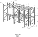
- FIG. 1 shows an example of a prior art storage rack that may be retrofitted to make a rack in accordance with the present invention.
- a preferred embodiment of the present invention is shown in FIGS. 2-11 .
- the rack of FIG. 1 has a multitude of forward columns 24, and a multitude of rear columns 36, and horizontal load beams 18 interconnecting the forward and rear columns 24, 36 to form levels to support palletized material.
- Each pair of forward and rear columns 24, 36 extends from a baseplate 26 and also includes horizontal forward-to-rear braces 14 and diagonal forward-to-rear braces 17.
- the back to back columns 36 have row spacers 16 that control the flue dimension.
- This rack is prone to damage from material handling equipment (MHE) when the operator is interfacing with the racking system. It is then very problematic and costly to repair the damage uprights as discussed above.
- MHE material handling equipment
- FIG. 2 shows a storage rack with a base steel structure assembly made up of structural components to greatly reduce the damage due to impact by the MHE.
- the upper portion of the front columns terminate above the first load beam level as the load beam connection adds additional durability and rigidity to the base steel structure assembly.
- This rack may be made in this form initially, or it may be made by retrofitting the prior art rack of FIG. 1 .
- This rack also has a front column 78, rear column 98, horizontal load beams 86 and horizontal pallet supports 66.
- the columns are supported by bolted horizontal forward-to-rear braces 58 and bolted diagonal forward-to-rear braces 60.
- the pallet supports interconnect via an angle bracket 64 to the front and rear horizontal load beams 86.
- a horizontal member 82 is bolted connected to the top of the front column 78 and the rear column 98.
- This horizontal member has an identical hole punch pattern on the front face of the material which corresponds to the baseplates' 26 hole pattern, this allows for a bolted connection between the upper and lower columns.
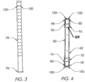
- FIG. 3 shows front column 78 with corresponding baseplate 70.
- the front column is punched with round holes to accept bolted connections as required.
- FIG. 4 shows a top view of the horizontal member 82 with corresponding front column 78 and rear column 98.
- the horizontal member would have holes 84, punched or otherwise formed on the front face of the material which correspond to the holes in the baseplate 26 in FIG. 2 to allow for a bolted connection.
- the front baseplate 70 and rear baseplate 96 which allow for the assembly to be anchored to the floor are also illustrated.
- a plate 80 is welded to each end of the horizontal structural member 82 which allows for a bolted connection between the front column 78 and the rear column 98.
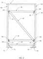
- FIG. 5 shows the base steel structure assembly fully assembled and prior to being connected to the above storage system.
- Bolted connections 100 allow for quick and easy replacement of damaged components all while the above storage system stays in place.
- the front column 78 and rear column 98 are typically rectangular or C-shaped structural members. The columns are supported by horizontal forward-to-rear braces 58 and diagonal forward-to-rear braces 60.
- the braces are bolted to tabs 74 and 76 on the front column and tabs 90 and 92 on the rear column. Before being welded to the columns the tabs are provided with holes through punching or otherwise to accept a bolted connection which allows for easy replacement of braces if ever damaged.
- the horizontal member 82 which is positioned at the top of the assembly is bolted to the front column 78 and rear column 98.
- This horizontal member allows for the columns in the above storage rack to remain in place during the replacement of any damaged structural component as it supports the load from both columns and is connected by bolts through said columns baseplates 26 in FIG. 1 .
- a vertical load jack 200 ( Figs. 9 and 11 ) may be installed under the horizontal member to take the above load while the required repairs are being completed.
- the horizontal channel 62 which is bolted to tabs 72 and 94 acts as a guard rail to further protect the critical bracing panel above from damage. This structural channel is considered a sacrificial component and is generally not considered in the engineering of the base steel structure assembly.
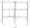
- FIG. 6 and 7 shows the base steel structure assembly connected to the above storage rack assembly as per the present invention.
- the front column 78 should terminate above the first load beam 86 as any lower and the lighter column material 24 in the above storage rack would be exposed to damage as it would more than likely fail before the structural material below.
- the structural bolted angle connectors 84 and 88 which are positioned on either end of the load beam 86, add further rigidity and durability to the base assembly and greatly restricts the transfer of forces from the MHE further up the column 78. This design configuration keeps the damage below the top horizontal member 82 in FIG. 5 thus allowing damage components to be replaced without the dismantling of the above storage rack.
- FIG. 8 shows the base steel structure assembly completely dismantled or prior to assembly as well as all the locations of the bolt 100 and nut 102 connections. This further shows the ease in which the front column or braces can be replaced in the event of damaged caused by the MHE.
- This view of the front column 78 further details the tabs 72, 74 and 76 which may be punched and welded to the web of the column.
- the plates 80 on either end of the top horizontal channel 82 may be punched and welded to allow for a bolted connection with the front column 78 and rear column 98. Having the plates 80 welded to the horizontal member 82 allows for the front column 78 to pull away without restriction from the assembly when being replaced due to damage.
- FIG. 9 shows the base steel structure assembly's front column 78 under repair.
- the vertical load jack 200 is installed under the top horizontal member 82 and fastened in place via a nut on the fixed bolt of the jack.
- the horizontal member 82 has pre-punched hole locations at either end of the member ( FIG. 11 ) to allow for the bolt from the vertical load jack to be positioned into as an added safety feature.
- the vertical load jack would then be ratcheted up to pick up the load from the above storage rack and release the shear load on the bolted connections of the base steel structure assembly below.
- the damaged component Upon removal of all bolted connections 100, the damaged component would be simply removed and a new component would be installed with new hardware.
- the vertical load jack would then be unbolted from the horizontal member 82 returning the above load to the base assembly below.
- FIG. 10 shows a detail view of the load beam 86 being bolted with bolts 100 through the beam connector 84 to the rear column 98.
- the above storage rack rear column 24 is bolted via the rear columns baseplate 26 to the base assemblies' top horizontal member 82. in the event of a repair to the base steel structure assembly, the top horizontal member 82 remains fixed to the above storage rack.
- FIG. 11 shows a detail view of the front column 78 of the base assembly being repaired.
- the vertical load jack is positioned with the bolt 100 through the top horizontal member 82 for the duration of the repair.
- the position of the top horizontal member plate 80 is instrumental in allowing the front column 78 to be removed without restriction upon the removal of all hardware.
- the punched and welded tab 76 has been released from the horizontal brace 58 and diagonal brace 60 by a single bolt connection.
- the front column 24 and subsequent baseplate 26 remain bolted to the top horizontal member 82 for the duration of the repair thus simplifying the entire process and greatly reducing the high cost associated with a complete dismantle.
- FIG. 12 shows the base assembly completely dismantled or prior to assembly with enhancements to the plates 180 and the top horizontal member 182 as compared to prior embodiments 80 and 82. All else remains the same.
- 182 By changing the structural material of 182 from channel to (formed and notched) plate, it allows for a wider more stable platform for the upper column 24 and subsequent baseplate 26 to sit on. The wider platform also allows for the acceptance of various baseplate 26 dimensions and anchor locations.
- the prior narrower embodiment 82 would have required manufacturers to modify their baseplates to suit causing reduced market acceptance and additional costs.
- the plates 180 which are now welded to the underside of 182 have been slightly recessed from either end of the top horizontal member thus allowing the plate material to extend to the front face of the front column 78 and rear column 98. This enhancement guarantees that the top horizontal member 182 always sits above the front column 78 and the rear column 98.
- Prior embodiments may have allowed for the top horizontal member 82 to rest below the front column 78 and rear column 98 creating unwanted stress on
- FIG. 13 shows the base assemblies in an exploded view for the rear column 98, the enhanced top horizontal member 182, the repositioned plate 180 as well as the horizontal brace 58 and diagonal brace 60.
- the explanation for enhancements to both 180 and 180 are explained in FIG. 12 .
Landscapes
- Engineering & Computer Science (AREA)
- Mechanical Engineering (AREA)
- Warehouses Or Storage Devices (AREA)
- Load-Engaging Elements For Cranes (AREA)
- Rod-Shaped Construction Members (AREA)
- Packaging Of Machine Parts And Wound Products (AREA)
- Working Measures On Existing Buildindgs (AREA)
Claims (4)
- Système de stockage comprenant un ensemble de structure métallique de base et un système de rayonnage superposé, dans lequel l'ensemble de structure métallique de base supporte le système de rayonnage superposé, ledit système de rayonnage comportant des colonnes verticales (24) qui supportent des poutres horizontales (18) s'étendant entre elles et reliées à elles, ledit ensemble de structure métallique de base comprenant :une colonne avant (78) s'étendant à partir d'une plaque de base avant (70) ;une colonne arrière (98) généralement parallèle à ladite colonne avant ets'étendant à partir d'une plaque de base arrière (96) ;un élément horizontal supérieur (82) s'étendant entre une extrémité supérieure desdites colonnes avant et arrière (78, 98) et fixé de manière amovible à celles-ci;un élément horizontal inférieur (58) s'étendant entre une extrémité inférieure desdites colonnes avant et arrière (78, 98) et fixé de manière amovible à celles-ci;au moins un renfort(6) s'étendant en diagonale entre lesdites colonnes avant etarrière (78, 98) et fixé de manière amovible à celles-ci;caractérisé en ce que ledit élément horizontal supérieur (82) peut être fixé auxdites colonnes verticales (24) dudit système de rayonnage superposé pour supporter ledit système de rayonnage superposé ; et,lesdites colonnes avant et arrière (78, 98) étant pourvues de trous (84) à travers celles-ci pour la fixation d'une poutre de support respectivement aux colonnes avant et arrière (78, 98) d'un ensemble adjacent dudit ensemble de structure métallique de base, et dans lequel lesdites colonnes verticales (24) s'étendent vers le haut à partir de plaques de base respectives (26) ;lesdites plaques de base respectives (26) ont des trous s'étendant à travers celles-ci ;ledit élément horizontal supérieur (82) est pourvu de trous à travers celui-ci qui s'alignent sur les trous dans les plaques de base respectives des colonnes verticales (24) pour le boulonnage des plaques de base respectives (26) à l'élément horizontal supérieur (82).
- Système de stockage selon la revendication 1, dans lequel lesdits éléments horizontaux supérieurs sont fixés de manière amovible auxdites colonnes avant et arrière à l'aide d'écrous (102) et de boulons (100).
- Système de stockage selon la revendication 1 ou 2, comportant un canal horizontal inférieur (62) boulonné entre lesdites colonnes avant et arrière (78, 98) sous l'élément horizontal inférieur (82) pour servir de garde-corps afin de protéger ledit au moins un renfort (6).
- Méthode de réparation d'un ensemble de structure métallique de base qui supporte un système de rayonnage superposé, ledit ensemble de structure métallique de base comprenant un élément horizontal supérieur (82) boulonné à celui-ci,
caractérisée en ce que ledit élément horizontal supérieur (82) peut être fixé audit système de rayonnage superposé pour supporter ledit système de rayonnage supérieur, ledit ensemble de structure métallique de base comportant une pluralité de composants structurels fixés de manière amovible par des boulons, ladite méthode comprenant les étapes suivantes :(i) le détachement dudit panneau de renfort horizontal et diagonal incluant le garde-corps ;(ii) le placement d'un vérin sous l'élément horizontal supérieur (82) ;(iii) le levage dudit vérin pour supporter ledit élément horizontal supérieur (82) ;(iv) le déboulonnage d'un composant endommagé parmi lesdits composants structurels ;(v) le retrait dudit composant structurel endommagé ;(vi) le remplacement dudit composant structurel endommagé par un composant structurel en bon état ;(vii) le boulonnage dudit composant structurel en bon état à un reste dudit ensemble de base ;(viii) l'abaissement dudit vérin(ix) le retrait dudit vérin ; et(x) la réinstallation dudit panneau de renfort horizontal et diagonal incluant le garde-corps.
Applications Claiming Priority (2)
| Application Number | Priority Date | Filing Date | Title |
|---|---|---|---|
| US201762543114P | 2017-08-09 | 2017-08-09 | |
| PCT/CA2018/050924 WO2019028546A1 (fr) | 2017-08-09 | 2018-07-30 | Ensemble de stockage à structure en acier de base interchangeable |
Publications (4)
| Publication Number | Publication Date |
|---|---|
| EP3664663A1 EP3664663A1 (fr) | 2020-06-17 |
| EP3664663A4 EP3664663A4 (fr) | 2021-04-21 |
| EP3664663C0 EP3664663C0 (fr) | 2023-06-07 |
| EP3664663B1 true EP3664663B1 (fr) | 2023-06-07 |
Family
ID=65273121
Family Applications (1)
| Application Number | Title | Priority Date | Filing Date |
|---|---|---|---|
| EP18843046.6A Active EP3664663B1 (fr) | 2017-08-09 | 2018-07-30 | Ensemble de stockage à structure en acier de base interchangeable |
Country Status (6)
| Country | Link |
|---|---|
| US (3) | US20200165064A1 (fr) |
| EP (1) | EP3664663B1 (fr) |
| AU (1) | AU2018313316B2 (fr) |
| CA (1) | CA3071446A1 (fr) |
| ES (1) | ES2950641T3 (fr) |
| WO (1) | WO2019028546A1 (fr) |
Families Citing this family (16)
| Publication number | Priority date | Publication date | Assignee | Title |
|---|---|---|---|---|
| CN112585070B (zh) * | 2018-09-07 | 2022-06-21 | 村田机械株式会社 | 自动仓库用货架 |
| US10974352B1 (en) * | 2019-03-04 | 2021-04-13 | Daniel V. Klinger | Modular pallet repair kit and method of use thereof |
| FR3094359B1 (fr) * | 2019-03-27 | 2021-04-02 | Saint Gobain | Rack de stockage adaptatif |
| AT16745U1 (de) * | 2019-05-27 | 2020-07-15 | Tgw Mechanics Gmbh | Regallagersystem und Regalrahmenteil für ein Regallagersystem |
| CN111700439A (zh) * | 2020-06-28 | 2020-09-25 | 贵州电网有限责任公司 | 一种货架安全托架 |
| CA3192968A1 (fr) * | 2020-09-16 | 2022-03-24 | Jared W. Hanlon | Rayonnage utilitaire |
| US11958686B2 (en) * | 2020-11-10 | 2024-04-16 | Apex Storage, LLC | Braces, method and process of use thereof for the repair of a storage rack |
| USD1045135S1 (en) * | 2021-04-20 | 2024-10-01 | Ronald K. HARRISON | Brace panel |
| EP4333671B1 (fr) * | 2021-05-04 | 2025-10-22 | Ronald Harrison | Ensemble support de crémaillère boulonné et procédé de réparation |
| US12588759B2 (en) | 2023-03-31 | 2026-03-31 | Virco Mfg. Corporation | Retaining bracket for modular shelving unit |
| US20250019161A1 (en) * | 2023-07-11 | 2025-01-16 | Spaceguard Products Inc. | Modular and adjustable upright repair device for industrial storage racks |
| US12383057B2 (en) * | 2023-07-14 | 2025-08-12 | Ll&T International, Llc | Knockdown bracing for shelving unit end frame |
| USD1093134S1 (en) | 2023-10-16 | 2025-09-16 | Adrian Steel Company | Shelf end panel footer |
| TWM653800U (zh) * | 2024-01-03 | 2024-04-01 | 欣業企業股份有限公司 | 層架裝置 |
| US20260096647A1 (en) * | 2024-10-07 | 2026-04-09 | Steel King Industries, Inc. | Hot rolled storage rack systems and methods |
| US12570465B1 (en) * | 2025-08-06 | 2026-03-10 | Pallet Rack Avenger.Com, Inc. | Retail pallet rack support assembly with reinforced base and replaceable shelf interface adapter |
Family Cites Families (20)
| Publication number | Priority date | Publication date | Assignee | Title |
|---|---|---|---|---|
| US3152670A (en) | 1960-02-01 | 1964-10-13 | Bernard Glockler North East Co | Pallet rack |
| US3647080A (en) * | 1970-06-12 | 1972-03-07 | Inca Metal Products Corp | Structural element and structure |
| US5749481A (en) * | 1994-01-03 | 1998-05-12 | Miller; Myron W. | Storage rack and structural beam therefor |
| CA2232178C (fr) * | 1998-03-13 | 1999-07-27 | Dany Dion | Systeme de reparation de palettier |
| US6405884B1 (en) * | 1998-09-09 | 2002-06-18 | Damotech Inc. | Pallet rack reinforcement unit |
| WO2001010749A1 (fr) | 1999-08-06 | 2001-02-15 | Interlake Material Handling, Inc. | Ensemble etagere de rangement a base decalee |
| US6332549B1 (en) | 2000-09-12 | 2001-12-25 | Macdonald Shawn D. | Repair kit for industrial pallet rack frame |
| US20040079718A1 (en) * | 2002-10-25 | 2004-04-29 | Jean-Paul Gagne | System allowing to expand the bottom or top of racks for widen the aisles or the shelves in a warehouse. |
| US20050150853A1 (en) * | 2004-01-12 | 2005-07-14 | Kimball Richard L. | Storage rack reinforcement/repair unit |
| US7311487B1 (en) * | 2004-10-29 | 2007-12-25 | Eric Crossley | Apparatus and method for repositioning warehouse shelving units |
| US7249442B2 (en) * | 2005-04-11 | 2007-07-31 | Ridg-U-Rak, Inc. | Storage rack vibration isolators and related storage rack systems |
| US7748546B2 (en) | 2006-01-27 | 2010-07-06 | Konstant Products, Inc. | Reinforced and bolted rack truss |
| US7828161B2 (en) * | 2007-10-24 | 2010-11-09 | Konstant Products, Inc. | Bases for storage rack trusses |
| US20090148267A1 (en) | 2007-12-10 | 2009-06-11 | Eric Crossley | Method for repositioning warehouse shelving units |
| US8172098B2 (en) * | 2008-05-06 | 2012-05-08 | Rapid Rack Industries, Inc. | Modular rack assembly |
| US20110278251A1 (en) * | 2010-05-14 | 2011-11-17 | Smith Scott C | Apparatus for a Pallet Rack |
| CA2711891A1 (fr) * | 2010-08-03 | 2012-02-03 | Jason W. Roberts | Systeme et trousse de reparation de cadre |
| US8443992B2 (en) * | 2010-09-21 | 2013-05-21 | Whalen Furniture Manufacturing, Inc. a California corporation | Industrial frame rack support assembly |
| DE202010015133U1 (de) * | 2010-11-04 | 2011-01-27 | Steger, Lutz | Unterbauständer für Regalrahmen |
| US10974352B1 (en) * | 2019-03-04 | 2021-04-13 | Daniel V. Klinger | Modular pallet repair kit and method of use thereof |
-
2018
- 2018-07-30 EP EP18843046.6A patent/EP3664663B1/fr active Active
- 2018-07-30 WO PCT/CA2018/050924 patent/WO2019028546A1/fr not_active Ceased
- 2018-07-30 AU AU2018313316A patent/AU2018313316B2/en active Active
- 2018-07-30 ES ES18843046T patent/ES2950641T3/es active Active
- 2018-07-30 US US16/637,231 patent/US20200165064A1/en not_active Abandoned
- 2018-07-30 CA CA3071446A patent/CA3071446A1/fr active Pending
-
2021
- 2021-06-18 US US17/351,437 patent/US11690446B2/en active Active
-
2023
- 2023-02-06 US US18/165,097 patent/US11882932B2/en active Active
Also Published As
| Publication number | Publication date |
|---|---|
| EP3664663A4 (fr) | 2021-04-21 |
| ES2950641T3 (es) | 2023-10-11 |
| WO2019028546A1 (fr) | 2019-02-14 |
| EP3664663A1 (fr) | 2020-06-17 |
| US20200165064A1 (en) | 2020-05-28 |
| EP3664663C0 (fr) | 2023-06-07 |
| US20230180929A1 (en) | 2023-06-15 |
| AU2018313316A1 (en) | 2020-03-19 |
| US20210371199A1 (en) | 2021-12-02 |
| CA3071446A1 (fr) | 2019-02-14 |
| US11690446B2 (en) | 2023-07-04 |
| US11882932B2 (en) | 2024-01-30 |
| AU2018313316B2 (en) | 2024-05-30 |
Similar Documents
| Publication | Publication Date | Title |
|---|---|---|
| US11882932B2 (en) | Interchangeable base steel structure storage assembly | |
| US10863646B1 (en) | Modular data center support rack system and installation method | |
| US10974352B1 (en) | Modular pallet repair kit and method of use thereof | |
| US7753220B2 (en) | Reinforced and bolted rack truss | |
| CA2757976C (fr) | Chariot a profil bas a rangement par retro-poussage et systeme de rangement de chariots par retro-poussage | |
| US7748546B2 (en) | Reinforced and bolted rack truss | |
| US20070278169A1 (en) | Frame adapted to be fitted inside an outer container | |
| US7828161B2 (en) | Bases for storage rack trusses | |
| US20050150853A1 (en) | Storage rack reinforcement/repair unit | |
| EP4333671B1 (fr) | Ensemble support de crémaillère boulonné et procédé de réparation | |
| US20080173603A1 (en) | Adjustable brace | |
| US20250019161A1 (en) | Modular and adjustable upright repair device for industrial storage racks | |
| CA2232178C (fr) | Systeme de reparation de palettier | |
| JP6929717B2 (ja) | 二・多段式駐車装置の改造方法と、この方法で改造された駐車設備 | |
| US20260096647A1 (en) | Hot rolled storage rack systems and methods | |
| US12570465B1 (en) | Retail pallet rack support assembly with reinforced base and replaceable shelf interface adapter | |
| CN222808681U (zh) | 一种仓库仓储用横梁式货架结构 | |
| KR20220029483A (ko) | 데이터 센터용 랙 | |
| JP6815204B2 (ja) | ラック制振装置の設置方法 | |
| CN215685912U (zh) | 一种方便按需快速组装的货架 | |
| CN216791240U (zh) | 试验平台及具有其的多层试验平台 | |
| AU2017100201A4 (en) | Method and system for protecting a pallet rack | |
| CN211766181U (zh) | 方便减摇鳍调试的支撑结构 | |
| KR101878602B1 (ko) | 하중 변화의 대응과 용이한 조립해체를 위한 인상용 강재브라켓 유닛 | |
| CN121419927A (zh) | 多层储存系统 |
Legal Events
| Date | Code | Title | Description |
|---|---|---|---|
| STAA | Information on the status of an ep patent application or granted ep patent |
Free format text: STATUS: THE INTERNATIONAL PUBLICATION HAS BEEN MADE |
|
| PUAI | Public reference made under article 153(3) epc to a published international application that has entered the european phase |
Free format text: ORIGINAL CODE: 0009012 |
|
| STAA | Information on the status of an ep patent application or granted ep patent |
Free format text: STATUS: REQUEST FOR EXAMINATION WAS MADE |
|
| 17P | Request for examination filed |
Effective date: 20200305 |
|
| AK | Designated contracting states |
Kind code of ref document: A1 Designated state(s): AL AT BE BG CH CY CZ DE DK EE ES FI FR GB GR HR HU IE IS IT LI LT LU LV MC MK MT NL NO PL PT RO RS SE SI SK SM TR |
|
| AX | Request for extension of the european patent |
Extension state: BA ME |
|
| DAV | Request for validation of the european patent (deleted) | ||
| DAX | Request for extension of the european patent (deleted) | ||
| A4 | Supplementary search report drawn up and despatched |
Effective date: 20210319 |
|
| RIC1 | Information provided on ipc code assigned before grant |
Ipc: A47B 53/00 20060101AFI20210315BHEP Ipc: A47B 55/00 20060101ALI20210315BHEP Ipc: B25H 3/04 20060101ALI20210315BHEP Ipc: B65D 19/30 20060101ALI20210315BHEP Ipc: B65G 1/10 20060101ALI20210315BHEP |
|
| RIC1 | Information provided on ipc code assigned before grant |
Ipc: B65G 1/02 20060101ALI20220912BHEP Ipc: B65D 19/30 20060101ALI20220912BHEP Ipc: B25H 3/04 20060101ALI20220912BHEP Ipc: A47B 55/00 20060101ALI20220912BHEP Ipc: A47B 53/00 20060101AFI20220912BHEP |
|
| GRAP | Despatch of communication of intention to grant a patent |
Free format text: ORIGINAL CODE: EPIDOSNIGR1 |
|
| STAA | Information on the status of an ep patent application or granted ep patent |
Free format text: STATUS: GRANT OF PATENT IS INTENDED |
|
| INTG | Intention to grant announced |
Effective date: 20221214 |
|
| GRAS | Grant fee paid |
Free format text: ORIGINAL CODE: EPIDOSNIGR3 |
|
| GRAA | (expected) grant |
Free format text: ORIGINAL CODE: 0009210 |
|
| STAA | Information on the status of an ep patent application or granted ep patent |
Free format text: STATUS: THE PATENT HAS BEEN GRANTED |
|
| AK | Designated contracting states |
Kind code of ref document: B1 Designated state(s): AL AT BE BG CH CY CZ DE DK EE ES FI FR GB GR HR HU IE IS IT LI LT LU LV MC MK MT NL NO PL PT RO RS SE SI SK SM TR |
|
| REG | Reference to a national code |
Ref country code: GB Ref legal event code: FG4D |
|
| REG | Reference to a national code |
Ref country code: CH Ref legal event code: EP Ref country code: AT Ref legal event code: REF Ref document number: 1572143 Country of ref document: AT Kind code of ref document: T Effective date: 20230615 Ref country code: DE Ref legal event code: R096 Ref document number: 602018051507 Country of ref document: DE |
|
| U01 | Request for unitary effect filed |
Effective date: 20230705 |
|
| U07 | Unitary effect registered |
Designated state(s): AT BE BG DE DK EE FI FR IT LT LU LV MT NL PT SE SI Effective date: 20230725 |
|
| U20 | Renewal fee for the european patent with unitary effect paid |
Year of fee payment: 6 Effective date: 20230727 |
|
| REG | Reference to a national code |
Ref country code: LT Ref legal event code: MG9D |
|
| REG | Reference to a national code |
Ref country code: ES Ref legal event code: FG2A Ref document number: 2950641 Country of ref document: ES Kind code of ref document: T3 Effective date: 20231011 |
|
| PG25 | Lapsed in a contracting state [announced via postgrant information from national office to epo] |
Ref country code: NO Free format text: LAPSE BECAUSE OF FAILURE TO SUBMIT A TRANSLATION OF THE DESCRIPTION OR TO PAY THE FEE WITHIN THE PRESCRIBED TIME-LIMIT Effective date: 20230907 |
|
| PG25 | Lapsed in a contracting state [announced via postgrant information from national office to epo] |
Ref country code: RS Free format text: LAPSE BECAUSE OF FAILURE TO SUBMIT A TRANSLATION OF THE DESCRIPTION OR TO PAY THE FEE WITHIN THE PRESCRIBED TIME-LIMIT Effective date: 20230607 Ref country code: HR Free format text: LAPSE BECAUSE OF FAILURE TO SUBMIT A TRANSLATION OF THE DESCRIPTION OR TO PAY THE FEE WITHIN THE PRESCRIBED TIME-LIMIT Effective date: 20230607 Ref country code: GR Free format text: LAPSE BECAUSE OF FAILURE TO SUBMIT A TRANSLATION OF THE DESCRIPTION OR TO PAY THE FEE WITHIN THE PRESCRIBED TIME-LIMIT Effective date: 20230908 |
|
| PG25 | Lapsed in a contracting state [announced via postgrant information from national office to epo] |
Ref country code: SK Free format text: LAPSE BECAUSE OF FAILURE TO SUBMIT A TRANSLATION OF THE DESCRIPTION OR TO PAY THE FEE WITHIN THE PRESCRIBED TIME-LIMIT Effective date: 20230607 |
|
| PG25 | Lapsed in a contracting state [announced via postgrant information from national office to epo] |
Ref country code: IS Free format text: LAPSE BECAUSE OF FAILURE TO SUBMIT A TRANSLATION OF THE DESCRIPTION OR TO PAY THE FEE WITHIN THE PRESCRIBED TIME-LIMIT Effective date: 20231007 |
|
| PG25 | Lapsed in a contracting state [announced via postgrant information from national office to epo] |
Ref country code: SM Free format text: LAPSE BECAUSE OF FAILURE TO SUBMIT A TRANSLATION OF THE DESCRIPTION OR TO PAY THE FEE WITHIN THE PRESCRIBED TIME-LIMIT Effective date: 20230607 Ref country code: SK Free format text: LAPSE BECAUSE OF FAILURE TO SUBMIT A TRANSLATION OF THE DESCRIPTION OR TO PAY THE FEE WITHIN THE PRESCRIBED TIME-LIMIT Effective date: 20230607 Ref country code: RO Free format text: LAPSE BECAUSE OF FAILURE TO SUBMIT A TRANSLATION OF THE DESCRIPTION OR TO PAY THE FEE WITHIN THE PRESCRIBED TIME-LIMIT Effective date: 20230607 Ref country code: IS Free format text: LAPSE BECAUSE OF FAILURE TO SUBMIT A TRANSLATION OF THE DESCRIPTION OR TO PAY THE FEE WITHIN THE PRESCRIBED TIME-LIMIT Effective date: 20231007 Ref country code: CZ Free format text: LAPSE BECAUSE OF FAILURE TO SUBMIT A TRANSLATION OF THE DESCRIPTION OR TO PAY THE FEE WITHIN THE PRESCRIBED TIME-LIMIT Effective date: 20230607 |
|
| PG25 | Lapsed in a contracting state [announced via postgrant information from national office to epo] |
Ref country code: PL Free format text: LAPSE BECAUSE OF FAILURE TO SUBMIT A TRANSLATION OF THE DESCRIPTION OR TO PAY THE FEE WITHIN THE PRESCRIBED TIME-LIMIT Effective date: 20230607 |
|
| REG | Reference to a national code |
Ref country code: CH Ref legal event code: PL |
|
| REG | Reference to a national code |
Ref country code: DE Ref legal event code: R097 Ref document number: 602018051507 Country of ref document: DE |
|
| PG25 | Lapsed in a contracting state [announced via postgrant information from national office to epo] |
Ref country code: MC Free format text: LAPSE BECAUSE OF FAILURE TO SUBMIT A TRANSLATION OF THE DESCRIPTION OR TO PAY THE FEE WITHIN THE PRESCRIBED TIME-LIMIT Effective date: 20230607 |
|
| PG25 | Lapsed in a contracting state [announced via postgrant information from national office to epo] |
Ref country code: MC Free format text: LAPSE BECAUSE OF FAILURE TO SUBMIT A TRANSLATION OF THE DESCRIPTION OR TO PAY THE FEE WITHIN THE PRESCRIBED TIME-LIMIT Effective date: 20230607 |
|
| PLBE | No opposition filed within time limit |
Free format text: ORIGINAL CODE: 0009261 |
|
| STAA | Information on the status of an ep patent application or granted ep patent |
Free format text: STATUS: NO OPPOSITION FILED WITHIN TIME LIMIT |
|
| REG | Reference to a national code |
Ref country code: IE Ref legal event code: MM4A |
|
| PG25 | Lapsed in a contracting state [announced via postgrant information from national office to epo] |
Ref country code: CH Free format text: LAPSE BECAUSE OF NON-PAYMENT OF DUE FEES Effective date: 20230731 |
|
| 26N | No opposition filed |
Effective date: 20240308 |
|
| PG25 | Lapsed in a contracting state [announced via postgrant information from national office to epo] |
Ref country code: IE Free format text: LAPSE BECAUSE OF NON-PAYMENT OF DUE FEES Effective date: 20230730 |
|
| PG25 | Lapsed in a contracting state [announced via postgrant information from national office to epo] |
Ref country code: IE Free format text: LAPSE BECAUSE OF NON-PAYMENT OF DUE FEES Effective date: 20230730 |
|
| U20 | Renewal fee for the european patent with unitary effect paid |
Year of fee payment: 7 Effective date: 20240729 |
|
| PG25 | Lapsed in a contracting state [announced via postgrant information from national office to epo] |
Ref country code: CY Free format text: LAPSE BECAUSE OF FAILURE TO SUBMIT A TRANSLATION OF THE DESCRIPTION OR TO PAY THE FEE WITHIN THE PRESCRIBED TIME-LIMIT; INVALID AB INITIO Effective date: 20180730 |
|
| PG25 | Lapsed in a contracting state [announced via postgrant information from national office to epo] |
Ref country code: HU Free format text: LAPSE BECAUSE OF FAILURE TO SUBMIT A TRANSLATION OF THE DESCRIPTION OR TO PAY THE FEE WITHIN THE PRESCRIBED TIME-LIMIT; INVALID AB INITIO Effective date: 20180730 |
|
| PG25 | Lapsed in a contracting state [announced via postgrant information from national office to epo] |
Ref country code: TR Free format text: LAPSE BECAUSE OF FAILURE TO SUBMIT A TRANSLATION OF THE DESCRIPTION OR TO PAY THE FEE WITHIN THE PRESCRIBED TIME-LIMIT Effective date: 20230607 |
|
| U21 | Renewal fee for the european patent with unitary effect paid with additional fee |
Year of fee payment: 8 Effective date: 20260115 |
|
| PGFP | Annual fee paid to national office [announced via postgrant information from national office to epo] |
Ref country code: GB Payment date: 20260115 Year of fee payment: 8 |
|
| PGFP | Annual fee paid to national office [announced via postgrant information from national office to epo] |
Ref country code: ES Payment date: 20260130 Year of fee payment: 8 |