EP3664702B1 - Systeme und verfahren zum sammeln physiologischer informationen eines benutzers - Google Patents
Systeme und verfahren zum sammeln physiologischer informationen eines benutzers Download PDFInfo
- Publication number
- EP3664702B1 EP3664702B1 EP18823618.6A EP18823618A EP3664702B1 EP 3664702 B1 EP3664702 B1 EP 3664702B1 EP 18823618 A EP18823618 A EP 18823618A EP 3664702 B1 EP3664702 B1 EP 3664702B1
- Authority
- EP
- European Patent Office
- Prior art keywords
- user
- module
- sensor array
- sensors
- sensor
- Prior art date
- Legal status (The legal status is an assumption and is not a legal conclusion. Google has not performed a legal analysis and makes no representation as to the accuracy of the status listed.)
- Active
Links
Images



Classifications
-
- A—HUMAN NECESSITIES
- A61—MEDICAL OR VETERINARY SCIENCE; HYGIENE
- A61B—DIAGNOSIS; SURGERY; IDENTIFICATION
- A61B5/00—Measuring for diagnostic purposes; Identification of persons
- A61B5/02—Detecting, measuring or recording for evaluating the cardiovascular system, e.g. pulse, heart rate, blood pressure or blood flow
- A61B5/0205—Simultaneously evaluating both cardiovascular conditions and different types of body conditions, e.g. heart and respiratory condition
-
- A—HUMAN NECESSITIES
- A61—MEDICAL OR VETERINARY SCIENCE; HYGIENE
- A61B—DIAGNOSIS; SURGERY; IDENTIFICATION
- A61B5/00—Measuring for diagnostic purposes; Identification of persons
- A61B5/02—Detecting, measuring or recording for evaluating the cardiovascular system, e.g. pulse, heart rate, blood pressure or blood flow
- A61B5/024—Measuring pulse rate or heart rate
- A61B5/02416—Measuring pulse rate or heart rate using photoplethysmograph signals, e.g. generated by infrared radiation
- A61B5/02427—Details of sensor
-
- A—HUMAN NECESSITIES
- A61—MEDICAL OR VETERINARY SCIENCE; HYGIENE
- A61B—DIAGNOSIS; SURGERY; IDENTIFICATION
- A61B5/00—Measuring for diagnostic purposes; Identification of persons
- A61B5/02—Detecting, measuring or recording for evaluating the cardiovascular system, e.g. pulse, heart rate, blood pressure or blood flow
- A61B5/026—Measuring blood flow
- A61B5/0295—Measuring blood flow using plethysmography, i.e. measuring the variations in the volume of a body part as modified by the circulation of blood therethrough, e.g. impedance plethysmography
-
- A—HUMAN NECESSITIES
- A61—MEDICAL OR VETERINARY SCIENCE; HYGIENE
- A61B—DIAGNOSIS; SURGERY; IDENTIFICATION
- A61B5/00—Measuring for diagnostic purposes; Identification of persons
- A61B5/05—Detecting, measuring or recording for diagnosis by means of electric currents or magnetic fields; Measuring using microwaves or radio waves
- A61B5/053—Measuring electrical impedance or conductance of a portion of the body
- A61B5/0531—Measuring skin impedance
-
- A—HUMAN NECESSITIES
- A61—MEDICAL OR VETERINARY SCIENCE; HYGIENE
- A61B—DIAGNOSIS; SURGERY; IDENTIFICATION
- A61B5/00—Measuring for diagnostic purposes; Identification of persons
- A61B5/68—Arrangements of detecting, measuring or recording means, e.g. sensors, in relation to patient
- A61B5/6801—Arrangements of detecting, measuring or recording means, e.g. sensors, in relation to patient specially adapted to be attached to or worn on the body surface
- A61B5/6802—Sensor mounted on worn items
- A61B5/681—Wristwatch-type devices
-
- A—HUMAN NECESSITIES
- A61—MEDICAL OR VETERINARY SCIENCE; HYGIENE
- A61B—DIAGNOSIS; SURGERY; IDENTIFICATION
- A61B2562/00—Details of sensors; Constructional details of sensor housings or probes; Accessories for sensors
- A61B2562/02—Details of sensors specially adapted for in-vivo measurements
- A61B2562/0204—Acoustic sensors
-
- A—HUMAN NECESSITIES
- A61—MEDICAL OR VETERINARY SCIENCE; HYGIENE
- A61B—DIAGNOSIS; SURGERY; IDENTIFICATION
- A61B2562/00—Details of sensors; Constructional details of sensor housings or probes; Accessories for sensors
- A61B2562/02—Details of sensors specially adapted for in-vivo measurements
- A61B2562/0219—Inertial sensors, e.g. accelerometers, gyroscopes, tilt switches
-
- A—HUMAN NECESSITIES
- A61—MEDICAL OR VETERINARY SCIENCE; HYGIENE
- A61B—DIAGNOSIS; SURGERY; IDENTIFICATION
- A61B2562/00—Details of sensors; Constructional details of sensor housings or probes; Accessories for sensors
- A61B2562/02—Details of sensors specially adapted for in-vivo measurements
- A61B2562/0223—Magnetic field sensors
-
- A—HUMAN NECESSITIES
- A61—MEDICAL OR VETERINARY SCIENCE; HYGIENE
- A61B—DIAGNOSIS; SURGERY; IDENTIFICATION
- A61B2562/00—Details of sensors; Constructional details of sensor housings or probes; Accessories for sensors
- A61B2562/02—Details of sensors specially adapted for in-vivo measurements
- A61B2562/0247—Pressure sensors
-
- A—HUMAN NECESSITIES
- A61—MEDICAL OR VETERINARY SCIENCE; HYGIENE
- A61B—DIAGNOSIS; SURGERY; IDENTIFICATION
- A61B2562/00—Details of sensors; Constructional details of sensor housings or probes; Accessories for sensors
- A61B2562/04—Arrangements of multiple sensors of the same type
-
- A—HUMAN NECESSITIES
- A61—MEDICAL OR VETERINARY SCIENCE; HYGIENE
- A61B—DIAGNOSIS; SURGERY; IDENTIFICATION
- A61B2562/00—Details of sensors; Constructional details of sensor housings or probes; Accessories for sensors
- A61B2562/06—Arrangements of multiple sensors of different types
- A61B2562/066—Arrangements of multiple sensors of different types in a matrix array
-
- A—HUMAN NECESSITIES
- A61—MEDICAL OR VETERINARY SCIENCE; HYGIENE
- A61B—DIAGNOSIS; SURGERY; IDENTIFICATION
- A61B5/00—Measuring for diagnostic purposes; Identification of persons
- A61B5/02—Detecting, measuring or recording for evaluating the cardiovascular system, e.g. pulse, heart rate, blood pressure or blood flow
- A61B5/021—Measuring pressure in heart or blood vessels
-
- A—HUMAN NECESSITIES
- A61—MEDICAL OR VETERINARY SCIENCE; HYGIENE
- A61B—DIAGNOSIS; SURGERY; IDENTIFICATION
- A61B5/00—Measuring for diagnostic purposes; Identification of persons
- A61B5/02—Detecting, measuring or recording for evaluating the cardiovascular system, e.g. pulse, heart rate, blood pressure or blood flow
- A61B5/024—Measuring pulse rate or heart rate
-
- A—HUMAN NECESSITIES
- A61—MEDICAL OR VETERINARY SCIENCE; HYGIENE
- A61B—DIAGNOSIS; SURGERY; IDENTIFICATION
- A61B5/00—Measuring for diagnostic purposes; Identification of persons
- A61B5/02—Detecting, measuring or recording for evaluating the cardiovascular system, e.g. pulse, heart rate, blood pressure or blood flow
- A61B5/024—Measuring pulse rate or heart rate
- A61B5/02405—Determining heart rate variability
-
- A—HUMAN NECESSITIES
- A61—MEDICAL OR VETERINARY SCIENCE; HYGIENE
- A61B—DIAGNOSIS; SURGERY; IDENTIFICATION
- A61B5/00—Measuring for diagnostic purposes; Identification of persons
- A61B5/02—Detecting, measuring or recording for evaluating the cardiovascular system, e.g. pulse, heart rate, blood pressure or blood flow
- A61B5/026—Measuring blood flow
- A61B5/0261—Measuring blood flow using optical means, e.g. infrared light
-
- A—HUMAN NECESSITIES
- A61—MEDICAL OR VETERINARY SCIENCE; HYGIENE
- A61B—DIAGNOSIS; SURGERY; IDENTIFICATION
- A61B5/00—Measuring for diagnostic purposes; Identification of persons
- A61B5/05—Detecting, measuring or recording for diagnosis by means of electric currents or magnetic fields; Measuring using microwaves or radio waves
- A61B5/053—Measuring electrical impedance or conductance of a portion of the body
-
- A—HUMAN NECESSITIES
- A61—MEDICAL OR VETERINARY SCIENCE; HYGIENE
- A61B—DIAGNOSIS; SURGERY; IDENTIFICATION
- A61B5/00—Measuring for diagnostic purposes; Identification of persons
- A61B5/05—Detecting, measuring or recording for diagnosis by means of electric currents or magnetic fields; Measuring using microwaves or radio waves
- A61B5/053—Measuring electrical impedance or conductance of a portion of the body
- A61B5/0531—Measuring skin impedance
- A61B5/0533—Measuring galvanic skin response
-
- A—HUMAN NECESSITIES
- A61—MEDICAL OR VETERINARY SCIENCE; HYGIENE
- A61B—DIAGNOSIS; SURGERY; IDENTIFICATION
- A61B5/00—Measuring for diagnostic purposes; Identification of persons
- A61B5/08—Measuring devices for evaluating the respiratory organs
- A61B5/0816—Measuring devices for examining respiratory frequency
-
- A—HUMAN NECESSITIES
- A61—MEDICAL OR VETERINARY SCIENCE; HYGIENE
- A61B—DIAGNOSIS; SURGERY; IDENTIFICATION
- A61B5/00—Measuring for diagnostic purposes; Identification of persons
- A61B5/145—Measuring characteristics of blood in vivo, e.g. gas concentration or pH-value ; Measuring characteristics of body fluids or tissues, e.g. interstitial fluid or cerebral tissue
- A61B5/1455—Measuring characteristics of blood in vivo, e.g. gas concentration or pH-value ; Measuring characteristics of body fluids or tissues, e.g. interstitial fluid or cerebral tissue using optical sensors, e.g. spectral photometrical oximeters
- A61B5/14551—Measuring characteristics of blood in vivo, e.g. gas concentration or pH-value ; Measuring characteristics of body fluids or tissues, e.g. interstitial fluid or cerebral tissue using optical sensors, e.g. spectral photometrical oximeters for measuring blood gases
-
- A—HUMAN NECESSITIES
- A61—MEDICAL OR VETERINARY SCIENCE; HYGIENE
- A61B—DIAGNOSIS; SURGERY; IDENTIFICATION
- A61B5/00—Measuring for diagnostic purposes; Identification of persons
- A61B5/48—Other medical applications
- A61B5/4869—Determining body composition
- A61B5/4875—Hydration status, fluid retention of the body
-
- A—HUMAN NECESSITIES
- A61—MEDICAL OR VETERINARY SCIENCE; HYGIENE
- A61B—DIAGNOSIS; SURGERY; IDENTIFICATION
- A61B5/00—Measuring for diagnostic purposes; Identification of persons
- A61B5/68—Arrangements of detecting, measuring or recording means, e.g. sensors, in relation to patient
- A61B5/6801—Arrangements of detecting, measuring or recording means, e.g. sensors, in relation to patient specially adapted to be attached to or worn on the body surface
- A61B5/6843—Monitoring or controlling sensor contact pressure
Definitions
- the embodiments relate generally to systems and methods for detecting physiological information from a user through a number of sensors, analyzing and/or measuring the detected information, and interpreting the information.
- the devices described herein include a watch, strap, or band that comprises a number of sensors, including but not limited to one or more of a PPG sensor, an ECG sensor, a pressure sensor, an acoustic sensor, and/or other suitable physiological sensors.
- the devices can include a pair of modules: an upper module that can be positioned on the top or outside of the wrist; and a lower module that can be positioned on the underside or inside of the wrist.
- optical sensors are used to detect variation in blood flow through arteries or blood volume in subcutaneous tissue. Applications include the monitoring of heart rate, glucose level, apnea, respiratory stress, and other physiological conditions.
- the optical sensors often comprise one or more light sources that illuminate a targeted portion of the human body and one or more associated optical detectors that receive a portion of the optical energy emitted by the light sources.
- transmissive sensor arrangements a relatively thin portion of the body such as the tip of the finger or the earlobe is positioned between a light source and a photo detector. Light that passes through the body tissue impinges on the photo detector resulting in an electrical signal that is synchronized to each heartbeat.
- reflective sensor arrangements a sensor that includes one or more light sources located in spaced apart juxtaposition with a photo detector is positioned against a targeted area of the body. Optical energy emitted by the light sources passes through the skin of the targeted tissue region, is scattered, partially absorbed, and is reflected by blood flowing through arteries and other vascular structure. The reflected optical energy is in effect modulated in accordance with blood flow in the targeted area and detected by the photo detector.
- the detected reflection can then be used to produce a signal pulse that is indicative of a physiological parameter such as a heartbeat.
- a physiological parameter such as a heartbeat.
- the signal produced by the photo detectors is processed to display or otherwise provide a real-time indication of the monitored physiological parameter.
- physiological monitors One area of growing interest in the use of physiological monitors is with respect to personal wellness and/or physical exercise for purposes of fitness training, weight loss, or monitoring general health. Technological advances relating to optical sensors, signal processing, and display devices have made it possible to realize small, light-weight physiological monitors that can be embodied as devices that may be worn by a user. Such wearable devices may include, for example, wrist watches, bracelets, and arm bands.
- the electronic circuitry for processing the signal produced by the photo detector and displaying an indication of the monitored parameter must operate at a low power level to provide adequate battery life while simultaneously providing sufficient accuracy.
- Constraints relating to the physical design of such monitors are not limited to the challenges of packaging the electronics and display units in an arrangement that can be worn by a user.
- Special considerations and constraints are present with respect to incorporation of the optical sensor, including but not limited to variations in physiological features across a large number of users.
- sensor designs that can accurately interpret or predict not just heart rate but other physiological parameters such as calorie expenditure, body movement, heart rate variability, respiration rate, blood pressure, and oxygen level have not been developed.
- WO 2015/061783A1 relates to systems and methods for obtaining bodily function measurements using a mobile device.
- EP 2007273 A1 relates to an imaging device designed with the intent of visualizing subcutaneous structures within an organism.
- WO 2013/030744 A1 relates to a pulse oximetry device mounted on a wrist strap and fixating an area above a distal end of the ulna with a dome shaped structure.
- an apparatus for determining a physiological parameter of a user comprises: at least one sensor array comprising at least one light source and at least one photo detector; a processor for analyzing the physiological information collected by the sensor array; a database comprising housing physiological information associated with a plurality of subjects, the database further comprising at least one directly measured physiological indicia associated with each subject.
- the physiological information collected by the sensor array is compared to the physiological information of the plurality of subjects in the database and a physiological indicia of the user is estimated based on the directly measured physiological indicia corresponding to one or more of the subjects.
- the physiological indicia is one of blood pressure, oxygen levels (SvO 2 ), hydration, respiration rate, and heart rate variability.
- the at least one sensor array collects information from the user indicative of the user's blood flow pulses.
- a plurality of features are extracted from the user's blood flow pulses and each of the extracted features are compared to one or more extracted features stored for each subject in the database.
- the plurality of features extracted from the user's blood flow pulses comprise features extracted from partial pulses, single pulses, and series of pulses.
- a wearable device for collecting a pulse signal of a user.
- the wearable device comprises: at least one module comprising at least one light source; a strap extending from the at least one module at an angle such that when the strap is used to secure the at least one module to a portion of the user's wrist, the at least one light source can be positioned above the user's CUN location while at least a portion of the strap is positioned away from the user's wrist joint.
- the at least one module comprises a first module comprising the at least one light source and a second module comprising at least one photo detector.
- the pulse signal is determined based on light transmitted through a portion of the user's wrist.
- the portion of the user's wrist is an edge of the user's wrist offset from a longitudinal extension of the user's arm.
- the at least one module further comprises one or more of an ECG electrode, a bio impedance sensor, a galvanic skin response sensor, a contact sensor, an accelerometer, a pressure sensor, an acoustic sensor, and an electromagnetic sensor.
- the at least one module comprises an inward facing sensor array and an outward facing sensor array, each of the inward and outward facing sensor arrays comprising at least one ECG electrode.
- the ECG electrode of the inward facing sensor array is configured for contact with a portion of the user's wrist and the ECG electrode of the outward facing sensor is configured for contact with a portion of a fingertip of the user.
- the apparatus may be a wearable device comprising an upper module and a lower module.
- the wearable device may be worn on a user's body such that one or more sensors of the upper and lower modules contact a targeted area of tissue.
- the wearable device is a watch, band, or strap that can be worn on the wrist of a user such that the upper and lower modules are each in contact with a side of the wrist.
- one or more sensors of the upper module may be in contact with or adjacent to the outer portion of the user's wrist and one or more sensors of the lower module may be in contact or adjacent to the inner portion of the user's wrist.
- Each of the upper and lower modules may comprise one or more sensors, including but not limited to optical/PPG sensors, ECG sensors/electrodes, bio impedance sensors, galvanic skin response sensors, tonometry/contact sensors, accelerometers, pressure sensors, acoustic sensors, and electromagnetic sensors.
- one or more optical/PPG sensors may comprise one or more light sources for emitting light proximate a targeted area of tissue and one or more optical detectors for detecting either reflected light (where an optical detector is located on the same side of the targeted area as the light source(s), i.e., within the same module) or transmitted light (where an optical detector is located opposite the light source(s), i.e., within an opposing module).
- the strap or band of the wearable device may be configured so at to facilitate proper placement of one or more sensors of the upper and/or lower modules while still affording the user a degree of comfort in wearing the device.
- the band may be configured to traverse the user's wrist or arm at an angle that brings one or more components of the upper or lower modules into contact with a specific targeted area of the user while allowing another portion of the band to rest at a positon on the user's wrist or arm that the user finds comfortable.
- the precise location of the upper and/or lower modules can be customized such that one or more sensors of either module can be placed in an ideal location of a user, despite the physiological differences between body types from user to user.
- the aforementioned features result in more comfortable wearable device while also increasing reliability and accuracy of the device sensing, measuring, analyzing, and displaying of physiological information.
- the physiological information sensed, measured, analyzed, or displayed can include but is not limited to heart rate information, ECG waveforms, calorie expenditure, step count, speed, blood pressure, oxygen levels, pulse signal features, and respiration rate.
- the physiological information may be blood pressure information.
- the physiological information may be any information associated with a physiological parameter derived from information received by one or more sensors of the wearable device. Regardless, the physiological information may be used in the context of, for example, health and wellness monitoring, athletic training, physical rehabilitation, and patient monitoring. Of course, these examples are only illustrative of the possibilities and the device described herein may be used in any suitable context.
- apparatus 100 may be a physiological monitor worn by a user to sense, collect, monitor, analyze, and/or display information pertaining to one or more physiological parameters.
- apparatus 100 may comprise a band, strap, or wrist watch.
- apparatus 100 may be any wearable monitor device configured for positioning at a user's wrist, arm, another extremity of the user, or some other area of the user's body.
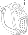
- apparatus 100 may comprise an upper module 110 and a lower module 150, each comprising one or more components and/or sensors for detecting, collecting, processing, and displaying one or more physiological parameters of a user and/or other information that may or may not be related to health, wellness, exercise, or physical training sessions.
- apparatus 100 may comprise a strap or band 105 extending from opposite edges of each module for securing apparatus 100 to the user.
- band(s) 105 may comprise an elastomeric material.
- band(s) 105 may comprise some other suitable material, including but not limited to, a fabric or metal material.
- Upper module 110 or lower module 150 may also comprise a display unit 112 for communicating information to the user.
- Display unit 112 may be an LED indicator comprising a plurality of LEDs, each a different color.
- the LED indicator can be configured to illuminate in different colors depending on the information being conveyed. For example, where apparatus 100 is configured to monitor the user's heart rate, display unit 112 may illuminate light of a first color when the user's heart rate is in a first numerical range, illuminate light of a second color when the user's heart rate is in a second numerical range, and illuminate light of a third color when the user's heart rate is in a third numerical range. In this manner, a user may be able to detect his or her approximate heart rate at a glance, even when numerical heart rate information is not displayed at display unit 112, and/or the user only sees apparatus 100 through his or her peripheral vision.
- display unit 112 may comprise a display screen for displaying images or characters to the user.
- Display unit 112 may further comprise one or more hard or soft buttons or switches configured to accept input by the user.
- Apparatus 100 may further comprise one or more communication modules.
- each of upper module 110 and lower module 150 comprise a communication module such that information received at either module can be shared with the other module.
- One or more communication modules can also be configured to communicate with other devices such as the user's cell phone, tablet, or computer. Communications between the upper and lower modules can be transmitted from one module to the other wirelessly (e.g., via Bluetooth, RF signal, WiFi, etc.) or through one or more electrical connections embedded in band 105.
- any analog information collected or analyzed by either module can be translated to digital information for reducing the size of information transfers between modules.
- communications between either module and another user device can be transmitted wirelessly or through a wired connection, and translated from analog to digital information to reduce the size of data transmissions.
- lower module 150 can comprise an array of sensors 155 including but not limited to one or more optical detectors 160, one or more light sources 165, and one or more contact pressure/tonometry sensors 170. These sensors are only illustrative of the possibilities, however, and lower module may comprise additional or alternative sensors such as one or more acoustic sensors, electromagnetic sensors, ECG electrodes, bio impedance sensors, galvanic skin response sensors, and/or accelerometers. Though not depicted in the view shown in Fig. 1 , upper module 110 may also comprise one or more such sensors and components on its inside surface, i.e. the surface in contact with the user's tissue or targeted area.
- band 105 may comprise an aperture or channel 175 within which lower module 150 is movably retained.
- lower module 150 and channel 175 can be configured to allow lower module 150 to slide along the length of channel 175 using, for example, a ridge and groove interface between the two components. In this manner, and as described in more detail below, where the user desires to place one more components of sensor array 155 at a particular location on his or her wrist, lower module 150 can be slid into the desired location along band 105.
- band 105 and upper module 110 can be similarly configured to allow for flexible or customized placement of one or more sensor components of upper module 110 with respect to the user's wrist or targeted tissue area.
- upper module 110 and/or lower module 150 may comprise additional sensors or components on their respective outer surfaces, i.e. the surfaces facing outward or away from the user's tissue.
- upper module 110 comprises one such outward facing sensor array 115.
- sensor array 115 may comprise one or more ECG electrodes 120. Similar to the sensor arrays of the upper and lower modules proximate or in contact with the user's tissue, outward facing sensor array 115 may further comprise one or more contact pressure/tonometry sensors, photo detectors, light sources, acoustic sensors, electromagnetic sensors, bio impedance sensors, galvanic skin response sensors, and/or accelerometers.
- outward facing sensors of sensor array 115 can be configured for activation when touched by the user (with his or her other hand) and used to collect additional information.
- outward facing sensor array 115 of upper module 110 may comprise ECG electrodes 120 that can be activated when the user places a fingertip in contact with the electrodes. While the optical detectors 160 and light sources 165 of lower module 150 can be used to continuously monitor blood flow of the user, outward facing sensor array 115 of upper module 110 can be used periodically or intermittently to collect potentially more accurate blood flow information which can be used to supplement or calibrate the measurements collected and analyzed by inward facing sensor array 155 of lower module 150.
- each module may further comprise other components for receiving, storing, analyzing, and/or transmitting physiological information. Some of those components are described below with respect to Fig. 8 .
- Fig. 2 depicts one embodiment of inward facing sensor array 155 of lower module 150.
- sensor array 155 can comprise sensors including but not limited to one or more optical detectors 160, one or more light sources 165, and one or more contact pressure/tonometry sensors 170. These sensors are only illustrative of the possibilities, however, and sensor array 155 may comprise additional or alternative sensors such as one or more acoustic sensors, electromagnetic sensors, ECG electrodes, bio impedance sensors, galvanic skin response sensors, and/or accelerometers.
- Upper module 110 may comprise a similar inward facing sensor array (not depicted in Fig. 1 ) configured to position sensors proximate or in contact with the outside portion of a user's wrist or arm.
- sensor components of the upper and lower modules 110, 150 can be used in combination to collect and analyze physiological information.
- one or more light sources of lower module 150 can be used to transmit light through a targeted area of the user's tissue (e.g., a portion of the user's wrist) and the transmitted light can be detected by one or more photodetectors of an inward facing sensor array of upper module 110.
- opposing modules 110 and 150 can be used to detect and analyze either reflected or transmitted light.
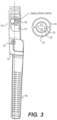
- Fig. 3 depicts another view of apparatus 100 comprising band 105, upper module 110, and lower module 150.
- lower module 150 can be placed within channel 175 of band 105 such that lower module 150 can slide along the longitudinal axis of band 105.
- the movability of lower module 150 (or upper module 110 in alternative embodiments) with respect to band 105 allows a user to customize the location of the inward facing sensors of lower module 150 with respect to a targeted tissue area to ensure reliable and accurate detection of physiological parameters. For example, a user can ensure that the inward facing sensors of lower module 150 are place in a location proximate the center of the user's radial artery.
- band 105 may not extend around the user's wrist such that it traverses a circumferential path lying in a plane perpendicular to the longitudinal axis of the user's wrist or arm. Rather, the longitudinal axis of band 105 extends at an angle such that portions of inward facing sensor arrays of upper or lower modules 110, 150 can be placed at suitable locations proximate a desired targeted area of tissue while a portion of band 105 is in contact with portions of the user's wrist or arm that the user finds comfortable (i.e., above or below the wrist joint).
- band 105 is set at an angle 107 with respect to the perpendicular plane.
- Angle 107 is between 5° and 15° with respect to the perpendicular plane. In other embodiments, angle 107 may be less than 5° or more than 15°.
- sensor array 115 may comprise one or more electrodes 120 for establishing an electrical connection with a user's fingertip and collected ECG data.
- Sensor array 115 may further comprise one or more contact pressure/tonometry sensors 125 for detecting the presence of the user's fingertip, which can trigger activation of electrodes 120.
- Sensor array 115 may also comprise additional or alternative components 130 such as one or more optical detectors, light sources, acoustic sensors, electromagnetic sensors, bio impedance sensors, galvanic skin response sensors, and/or accelerometers.
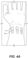
- Fig. 4A depicts some points of interest on a human wrist.
- the best point on the wrist for detecting blood flow is at a location coinciding with the wrist joint, approximately at location 1 shown as item 410.
- This location is proximate the radial artery and is referred to as the CUN location.
- the ideal location for a user to wear a wrist worn device is along the line across a line comprising locations 1-3-5.
- most users prefer to wear straps or bands off the wrist joint, for example, across locations 2-4-6 shown as item 420. The result is that in most cases, users wear their monitors and corresponding sensors at a location on their wrist or arm that is not ideal and likely to introduce errors in the detection of physiological parameters.
- the band angle 107 described with respect to Fig. 3 cures this deficiency in that it allows one or more sensor components of lower module 150 to be located above the CUN location while allowing a portion of the remaining band and/or upper module 110 to be positioned at a more comfortable location on the user's wrist or arm, such as line 2-4-6 (item 420).
- lower module 150 can slide along band 105. This allows the user to make further adjustments to the location of one or more sensors, not just along the longitudinal extension of the user's arm when apparatus 100 is in use, but also along the circumferential extension of band 105 while apparatus 100 is in use.
- band 105 extending around the user's wrist at an angle 107 together with the ability to slide lower module 150 along band 105, ensure the sensors of lower module 150 can be placed at an ideal location with respect to each user (even users of different body types and physical attributes) and that the physiological parameters detected and analyzed by apparatus 100 are collected as accurately as possible.
- apparatus 100 configured so as to ensure proper placement of one or more sensors and comfortability of band 105, but it also may contain additional sensors, such as a pressure sensor, at locations of apparatus 100 other than upper and lower modules 110, 150.
- apparatus 100 may comprise a pressure sensor located somewhere else along strap 105 or at a latch that secures opposing ends of band 105 around a user's wrist for detecting pressure.
- a sensor can be used to ensure that the user is wearing apparatus 100 tightly enough to ensure one more other sensors are in sufficient contact with a targeted area of the user's tissue to collect accurate physiological information.
- one or more pressure sensors of the upper and/or lower modules 110, 150 can be used to make the same determination.
- apparatus 100 may also be configured to alert the user (for example, via display unit 112 of upper module 110) if apparatus 100 is being worn too loosely or too tightly to ensure accurate measurements.
- Fig. 4B depicts one example of desirable locations for one or more sensors to placed with respect to a user's wrist or other targeted area.
- one or more sensors of lower module 150 can be placed adjacent or proximate point 410 (i.e., the CUN location) and one or more sensors of upper module 110 can be placed opposite point 410 at point 450 of the user's wrist or targeted area.
- Such a configuration provides the aforementioned benefits associated with proper placement of sensors over the CUN location, but also allows for apparatus 100 to detect, collect, and analyze blood flow through the radial artery using either reflective or transmissive systems.
- Wrist worn PPG sensors currently use a reflective system whereby a sensor array comprises one or more light sources and one or more optical detectors, located near one another and on the same side of a user's targeted area.
- the one or more light sources of the sensor array illuminate a portion of the user's tissue and light is reflected back to the optical detector(s) of the sensor array.
- the reflected light detected by the optical detector can be analyzed to estimate physiological parameters such as blood flow and pulse rate.
- An example schematic depicting a reflective system is shown below:
- transmissive systems may not be as accurate as transmissive systems that place one or more light sources on one side of a user's body and optical detectors on an opposing side of the user's body.
- a transmissive system are fingertip monitors used in a clinical setting. The monitors are clipped to a patient's fingertip, one side comprising a light source for illuminating the top or bottom of the patient's fingertip, the other side comprising an optical detector for detecting the light transmitted through the fingertip.
- apparatus 100 solves this problem by taking advantage of the natural location of the CUN location (the location of the radial artery at the wrist) at the inside of the wrist just under the thumb. As shown in Figs.
- apparatus 100 can be configured to place lower module 150 comprising a light source (and/or optical detector) at the location of the CUN artery on the underside of the wrist and place the upper module 110 comprising an opposing optical detector (or light source) at a location opposite the sensors of the lower module at the periphery of the outside of the wrist just below the thumb.
- the path of light transmitted through the wrist between the sensors of the lower and upper modules travels a shorter distance (shown in Fig. 4B ) than if the sensors were located closer to the center of the inside and outside of a user's wrist.
- light illuminated from either the upper or lower module can be detected at the opposing module in a manner previously only available in clinical settings and limited to locations on the body such as the fingertip.
- apparatus 100 may comprise a number of components and sensors for detecting physiological information and extracting data from it, such as blood flow, heart rate, respiratory rate, blood pressure, steps, calorie expenditure, and sleep.
- ECG electrodes/sensors bio impedance sensors, galvanic skin response sensors, tonometry/contact sensors, accelerometers, pressure sensors, acoustic sensors, and electromagnetic sensors
- One method for determining the heart rate, respiratory rate, blood pressure, oxygen levels, and other parameters of a user involves collecting a signal indicative of blood flow pulses from a targeted area of the user's tissue. As described above, this information can be collected using, for example, a light source and a photo detector. Some embodiments may use multiple light sources and they may be of varying colors. For example, one light source may be an IR light source and another might be an LED light (such as a red LED).
- Such embodiments may comprise multiple photo detectors, one or more configured to detect colored LED light (such as red) and one or more configured to detect IR light. These photo detectors (for detecting light of different wavelengths) can be combined into a single photodiode or maintained separate from one another. Further, the one or more light sources and one or more photodetectors could reside in the same module (upper or lower) in the case of a reflective system or the light source(s) could reside in one module while the optical detector(s) reside in the other in the case of a transmissive system.
- a number of parameters can be extracted from both single pulses and a waveform comprising multiple pulses.
- Fig. 6A depicts a single pulse from which a number of features or parameters can be extracted.
- Features or parameters extracted from a single pulse can include, but are not limited to, shape of the pulse, a maximum amplitude, a minimum amplitude, a maximum derivative, a time difference between main and secondary peaks, and integral through the entire extraction time (i.e., the area under the pulse).
- Figs. 6B and 6C illustrate that even portions of a single pulse can be analyzed for feature extraction. Extracting features at this level of detail has a number of advantages, including the ability to capture a great number of pulse features and store each of those features digitally without having to retain the analog waveform. The result is a savings in storage requirements and ease of data transmission.
- Feature extraction can also be performed on a number of pulses or a "pulse train.”
- Fig. 7 depicts a series of pulses overlaid with one another to show the variation among the group with respect to an identified feature. In this manner, the total variation among a series of pulses with respect to a single feature can be determined. The average of a group of pulses with respect to a single feature and the standard deviation of the group with respect to the feature can also be determined. Of course, these are just examples of the types of information that can be collected from a comparison of a single feature over a group of pulses. Moreover, while Fig.
- FIG. 7 depicts the extraction of a single feature from the group of pulses, it should be appreciated that any number of features can be extracted from the group in a manner similar to that described above with respect to a single pulse.
- Fig. 7 further depicts how information collected about a single feature over a group of pulses can be digitized or presented in a histogram 720.
- a PPG system comprising one or more light sources and/or one or more optical detectors
- additional sensors such as ECG electrodes/sensors, bio impedance sensors, galvanic skin response sensors, tonometry/contact sensors, accelerometers, pressure sensors, acoustic sensors, and electromagnetic sensors.
- one or more tonometry/contact sensors can be used to extract tonometry information by measuring the contact vessel pressure.
- one or more acoustic sensors comprising a speaker-microphone combination (such as a micro-electro-mechanical system (“MEMS”) acoustic sensor) can be used to extract reflected sound pulses from moving vessel walls.
- MEMS micro-electro-mechanical system
- one or more electromagnetic sensor MEMS can be used to extract voltage induced by coils or magnet pieces pressed to moving vessel walls.
- external or outward facing sensors can be configured to activate when touched by the off-hand (i.e., the hand on which apparatus 100 is not being worn) to collect additional information to help supplement or calibrate the information collected by the inward facing sensors of the upper or lower modules.
- the user can place a fingertip of his or her offhand on an outward facing ECG electrode (such as that shown in Fig. 1 ) to collect a more precise heart rate measurement.
- an outward facing ECG electrode such as that shown in Fig. 1
- heart rate measurement can be used to aid in the interpretation of the continuous heart rate measurements collected by the inward facing PPG sensors.
- the outward facing sensor can also comprise other sensors previously described herein, such as one or more contact/tonometry sensors, one or more bio impedance sensors, and one or more galvanic skin response sensors for analyzing electric pulse response. All of the information collected by an outward facing sensor from, for example, the fingertip of the user's off-hand, can be used to refine the analysis of the continuous measurements taken by any one or more of the inward facing sensors.
- apparatus 100 may further comprise additional internal components such as one or more accelerometers and/or gyroscopic components for determining whether and to what extent the user is in motion (i.e., whether the user is walking, jogging, running, swimming, sitting, or sleeping).
- Information collected by the accelerometer(s) and/or gyroscopic components can also be used to calculate the number of steps a user has taken over a period of time. This activity information can also be used in conjunction with physiological information collected by other sensors (such as heart rate, respiration rate, blood pressure, etc.) to determine a user's caloric expenditure and other relevant information.
- determining a user's blood pressure can comprise collecting a heart rate signal using a PPG system (i.e., one or more light sources and photo detectors) and performing feature extraction (described above) on single pulses and a series of pulses.
- a PPG system i.e., one or more light sources and photo detectors
- feature extraction described above
- the features extracted from single pulses and series of pulses can include statistical averages of various features across a series, information regarding the morphological shape of each pulse, the average and standard deviation of morphology of a series of pulses, temporal features such as the timing of various features within single pulses, the duration of a single pulse, as well as the average and standard deviation of the timing of a feature or duration of pulses within a series of pulses, and the timing of morphological features across a series of pulses (i.e., the frequency with which a particular pulse shape occurs in a series).
- this feature extraction can not only be performed on a series of pulses and single pulses, but also on portions of a single pulse.
- information pertaining to both systolic and diastolic blood pressure can be ascertained as one or more portions of an individual pulse correspond to the heart's diastole (relaxation) phase and one or more other portions of an individual pulse correspond to the heart's systole (contraction) phase.
- up to 60 features can be extracted from a partial pulse, a single pulse, and/or a series of pulses. In alternative embodiments, fewer or more features may be extracted.
- information and features can also be collected by contract/tonometry sensors, pressure sensors, bio impedance sensors galvanic skin response sensors, accelerometers, acoustic sensors, and electromagnetic sensors.
- pressure sensors or bio impedance sensors can be used to identify blood flow pulses of user and, similar to PPG or ECG data, features can be extracted from the collected data.
- the extracted features can then be cross-referenced or compared to entries in a library containing data corresponding to a population of subjects.
- the library may contain information associated with each extracted feature.
- the library can also contain a direct measured or verified blood pressure for each subject.
- the library may contain more than one directly measured or verified blood pressure measurement for each subject, each corresponding to a subject in a different condition, such as one corresponding to the subject at rest, one corresponding to the subject engaged in light activity, and one corresponding to the subject engaged in strenuous activity.
- the extracted features of the user can be compared to entries in the library to find one or more subjects with which the user's extracted features most closely compare and the user's blood pressure can then be estimated based on the verified blood pressure of those subjects.
- a standard deviation or range of variation across the series can be ascertained.
- a large variation across a series of pulses can be associated with flexible, healthy veins.
- individuals exhibiting large pulse-to-pulse variations across a series of pulses typically have relatively low blood pressure.
- little to no variation in features across a series of pulses is typically associated with relatively high blood pressure.
- the library described above can be generated by extracting the same features from partial pulses, individual pulses, and series of pulses across hundreds or thousands of subjects.
- the subjects' verified blood pressure can also be measured such that it can be associated with each feature extracted from the subject's pulse information.
- the subject entries in the library can also be sorted based on information helpful for estimating blood pressure. For example, subjects in the library can be identified as male or female, belonging to a particular age group, or associated with one or more past health conditions. Individual subjects can be associated with information indicative of the subject's sex, age, weight, race, and any other medically meaningful distinction.
- entries can be associated with information collected by other sensors at the time the verified blood pressure measurement was taken, including information collected by contract/tonometry sensors, pressure sensors, bio impedance sensors galvanic skin response sensors, accelerometers, acoustic sensors, and electromagnetic sensors.
- information collected by contract/tonometry sensors including information collected by contract/tonometry sensors, pressure sensors, bio impedance sensors galvanic skin response sensors, accelerometers, acoustic sensors, and electromagnetic sensors.
- a user is determined to be engaged in physical activity (through a combination of accelerometer and heart rate data, as an example)
- his or her extracted features may only be compared to data in the library corresponding to subjects engaged in similar physical activity.
- Information pertaining to subjects contained in the library may also be correlated to each subject's resting heart rate, BMI, or some other medically significant indicia.
- her extracted features should be compared to subjects in the library identified as young females with low resting heart rate whose blood pressure was verified during moderate activity rather than comparing the user's extracted features to an elderly male subject with a relatively high resting heart rate and whose blood pressure was verified during strenuous activity.
- apparatus 100 can also weigh the entries of subjects most closely corresponding to the user more heavily than entries of subjects associated with indicia different from that of the user. For example, if the user is a male, features extracted from male subjects may be weighed more heavily than female subjects because a particular pulse variation in men of a particular age may correspond to relatively high blood pressure whereas the same pulse variation in women of that particular age may correspond to lower blood pressure.
- accurate blood pressure estimates for a user can made without requiring direct blood pressure measurement of the user.
- the user's blood pressure estimates can be further calibrated by direct measurement of the user's blood pressure by another device and that verified blood pressure can be input into apparatus 100 to aid in future estimations of the user's blood pressure.
- Calibration can also be accomplished with an outward facing ECG sensor. While an inward facing PPG sensor can continuously or periodically collect heart rate data of a user, occasionally the user may be prompted to place a fingertip of his or her off-hand on an outward facing ECG sensor (e.g., electrodes).
- the inward facing sensor arrays of apparatus 100 may contain additional electrodes thereby completing an electrical circuit through the user's body and allowing a more precise pulse waveform to be collected. Feature extraction can be performed on these pulses, series of pulses, and partial pulses in the same manner as described above with respect to PPG information and used to cross-reference the library.
- apparatus 100 may prompt the user to place a fingertip of his or her off-hand on an outward facing ECG electrode in order to verify the unusual or unsafe condition. If necessary, apparatus 100 can then alert the user to call for help or seek medical assistance.
- the upper and/or lower modules 110, 150 can be configured to continuously collect data from a user using its inward facing sensor arrays. However, certain techniques can be employed to reduce power consumption and conserve battery life of apparatus 100. For instance, in some embodiments, only one of the upper or lower modules 110, 150 may continuously collect information. In alternative embodiments, neither module may be continuously active, but may wait to collect information when conditions are such that accurate readings are most likely. For example, when one or more accelerometers or gyroscopic components of apparatus 100 indicate that a user is still, at rest, or sleeping, one or more sensors of upper and/or lower module 110, 150 may collect information from the user while artifacts resulting from physical movement are absent.
- While techniques for estimating a user's blood pressure using pulse signal, pressure, impedance, and other collected and input information has been described above, it should be appreciated that similar techniques can be employed to estimate a user's oxygen levels (SvO 2 ), hydration, respiration rate, and heart rate variability.
- PPG, ECG, bio impedance, and acoustic measurements taken from the user can be cross-referenced with the aforementioned library and compared to subjects most closely matching the user (e.g., sex, age, height, weight, race, resting heart rate, BMI, current activity level, and any other medically meaningful distinction.
- Measured or verified hydration levels of one or more subjects can then be used to estimate the hydration level of the user.
- a similar process can be employed to estimate the user's oxygen levels (SvO 2 ), respiration rate, and heart rate variability.
- Fig. 8 depicts an illustrative processor-based computing system 800 representative of the type of computing system that may be present in or used in conjunction with any aspect of apparatus 100 comprising electronic circuitry.
- Each of upper or lower modules 110, 150 may comprise any one or more components of system 800.
- one module may contain one of the components of system 800 and the other module, rather than comprising a similar component, may be in wired or wireless communication with the component residing in the other first module.
- each module may comprise a similar component as compared to the other module such that it is not necessary to communication with the first module to enjoy the functionality of the component.
- upper module 110 may comprise storage, a power source, and/or a charging port
- lower module 150 may have access to the upper module's storage and/or draw power from the power source of the upper module through a wired or wireless connection.
- each module may have its own storage and/or power source.
- computing system 800 will be described herein as if it encompasses the components of upper and lower modules 110, 150 collectively, while the reader appreciates that one or more components described herein may reside only in one module or may be found in both modules.
- Processor-based computing system 800 may be used in conjunction with any one or more of transmitting signals to and from the one or more accelerometers, sensing or detecting signals received by one or more sensors of apparatus 100, processing received signals from one or more components or sensors of apparatus 100 or a secondary device, and storing, transmitting, or displaying information.
- Computing system 800 is illustrative only and does not exclude the possibility of another processor- or controller-based system being used in or with any of the aforementioned aspects of apparatus 100.
- system 800 may include one or more hardware and/or software components configured to execute software programs, such as software for storing, processing, and analyzing data.
- system 800 may include one or more hardware components such as, for example, processor 805, a random access memory (RAM) module 810, a read-only memory (ROM) module 820, a storage system 830, a database 840, one or more input/output (I/O) modules 850, an interface module 860, and one or more sensor modules 870.
- system 800 may include one or more software components such as, for example, a computer-readable medium including computer-executable instructions for performing methods consistent with certain disclosed embodiments.
- hard ware components listed above may be implemented using software.
- storage 830 may include a software partition associated with one or more other hardware components of system 800.
- System 800 may include additional, fewer, and/or different components than those listed above. It is understood that the components listed above are illustrative only and not intended to be limiting or exclude suitable alternatives or additional components.
- Processor 805 may include one or more processors, each configured to execute instructions and process data to perform one or more functions associated with system 800.
- processor 805 may be communicatively coupled to RAM 810, ROM 820, storage 830, database 840, I/O module 850, interface module 860, and one more sensor modules 870.
- Processor 805 may be configured to execute sequences of computer program instructions to perform various processes, which will be described in detail below. The computer program instructions may be loaded into RAM for execution by processor 805.
- RAM 810 and ROM 820 may each include one or more devices for storing information associated with an operation of system 800 and/or processor 805.
- ROM 820 may include a memory device configured to access and store information associated with system 800, including information for identifying, initializing, and monitoring the operation of one or more components and subsystems of system 800.
- RAM 810 may include a memory device for storing data associated with one or more operations of processor 805.
- ROM 820 may load instructions into RAM 810 for execution by processor 805.
- Storage 830 may include any type of storage device configured to store information that processor 805 may need to perform processes consistent with the disclosed embodiments.
- Database 840 may include one or more software and/or hardware components that cooperate to store, organize, sort, filter, and/or arrange data used by system 800 and/or processor 805.
- database 840 may include user profile information, historical activity and user-specific information, physiological parameter information, predetermined menu/display options, and other user preferences.
- database 840 may store additional and/or different information.
- I/O module 850 may include one or more components configured to communicate information with a user associated with system 800.
- I/O module 850 may comprise one or more buttons, switches, or touchscreens to allow a user to input parameters associated with system 800.
- I/O module 850 may also include a display including a graphical user interface (GUI) and/or one or more light sources for outputting information to the user.
- GUI graphical user interface
- I/O module 850 may also include one or more communication channels for connecting system 800 to one or more secondary or peripheral devices such as, for example, a desktop computer, a laptop, a tablet, a smart phone, a flash drive, or a printer, to allow a user to input data to or output data from system 800.
- Interface 860 may include one or more components configured to transmit and receive data via a communication network, such as the Internet, a local area network, a workstation peer-to-peer network, a direct link network, a wireless network, or any other suitable communication channel.
- interface 860 may include one or more modulators, demodulators, multiplexers, demultiplexers, network communication devices, wireless devices, antennas, modems, and any other type of device configured to enable data communication via a communication network.
- System 800 may further comprise one or more sensor modules 870.
- sensor modules 870 may comprise one or more of an accelerometer module, an optical sensor module, and/or an ambient light sensor module.
- these sensors are only illustrative of a few possibilities and sensor modules 870 may comprise alternative or additional sensor modules suitable for use in apparatus 100.
- sensor modules 870 may comprise alternative or additional sensor modules suitable for use in apparatus 100. It should be noted that although one or more sensor modules are described collectively as sensor modules 870, any one or more sensors or sensor modules within apparatus 100 may operate independently of any one or more other sensors or sensor modules.
- any one or more sensors of sensor module 870 may be configured to collect, transmit, or receive signals or information to and from other components or modules of system 800, including but not limited to database 840, I/O module 850, or interface 860.
- Additional features may also be incorporated into the described systems and methods to improve their functionality.
- physiological monitoring devices including but not limited to heart rate and blood pressure monitors, and that various sensor components may be employed.
- the devices may or may not comprise one or more features to ensure they are water resistant or waterproof. Some embodiments of the devices may hermetically sealed.
Landscapes
- Health & Medical Sciences (AREA)
- Life Sciences & Earth Sciences (AREA)
- Heart & Thoracic Surgery (AREA)
- Surgery (AREA)
- Physics & Mathematics (AREA)
- Veterinary Medicine (AREA)
- Biophysics (AREA)
- Pathology (AREA)
- Engineering & Computer Science (AREA)
- Biomedical Technology (AREA)
- Public Health (AREA)
- Medical Informatics (AREA)
- Molecular Biology (AREA)
- General Health & Medical Sciences (AREA)
- Animal Behavior & Ethology (AREA)
- Cardiology (AREA)
- Physiology (AREA)
- Dermatology (AREA)
- Pulmonology (AREA)
- Hematology (AREA)
- Radiology & Medical Imaging (AREA)
- Nuclear Medicine, Radiotherapy & Molecular Imaging (AREA)
- Measuring Pulse, Heart Rate, Blood Pressure Or Blood Flow (AREA)
Claims (7)
- Einrichtung (100) zum Bestimmen eines physiologischen Parameters eines Benutzers, wobei die Einrichtung (100) eine tragbare Vorrichtung ist und umfasst:ein erstes Modul (110), das in Kontakt mit oder benachbart zu einem äußeren Teil eines Handgelenks des Benutzers ist, wenn die Vorrichtung an dem Benutzer befestigt ist;ein zweites Modul (150), das in Kontakt mit oder benachbart zu einem inneren Teil des Handgelenks des Benutzers ist, wenn die Vorrichtung an dem Benutzer befestigt ist;
undein Band (105), das konfiguriert ist, um das erste Modul (110) und das zweite Modul (150) an einem Handgelenk des Benutzers zu befestigen, wenn die Vorrichtung an dem Benutzer befestigt ist,wobei das erste Modul (110) eine erste Sensoranordnung an einer nach innen gerichteten Oberfläche des Moduls, die für den Kontakt mit einem ersten Zielbereich des Benutzers konfiguriert ist, und eine zweite Sensoranordnung (115) an einer nach außen gerichteten Oberfläche des Moduls umfasst;wobei das zweite Modul (150) eine dritte Sensoranordnung (155) an einer nach innen gerichteten Oberfläche des Moduls umfasst, die für den Kontakt mit einem zweiten Zielbereich des Benutzers konfiguriert ist;dadurch gekennzeichnet, dass sich das Band (105) von dem ersten Modul (110) in einem Winkel zwischen 5° und 15° in Bezug auf eine Ebene senkrecht zu einer Längserstreckung des Arms oder Handgelenks des Benutzers derart erstreckt, dass, wenn es an dem Benutzer befestigt ist, die Umfangserstreckung des Bands in einer Ebene liegt, die nicht senkrecht zu einer Linie ist, die der Längserstreckung des Arms des Benutzers entspricht, und sich die dritte Sensoranordnung (155) nahe einer Mitte einer Speichenarterie des Benutzers befindet;die erste Sensoranordnung und die zweite Sensoranordnung jeweils eine oder mehrere Elektroden umfassen, wobei die eine oder die mehreren Elektroden der ersten Sensoranordnung für den Kontakt an dem Arm des Benutzers, an dem die Einrichtung befestigt ist, konfiguriert sind und die eine oder die mehreren Elektroden der zweiten Sensoranordnung für den Kontakt mit einer Fingerspitze des Benutzers an einem gegenüberliegenden Arm konfiguriert sind. - Einrichtung nach Anspruch 1, wobei die erste Sensoranordnung für den Kontakt mit der Außenseite des Arms des Benutzers nahe des Handgelenks des Benutzers konfiguriert ist.
- Einrichtung nach Anspruch 1 oder 2, wobei die dritte Sensoranordnung (155) für den Kontakt mit der Innenseite des Arms des Benutzers nahe des Handgelenks des Benutzers konfiguriert ist.
- Einrichtung nach einem der Ansprüche 1 bis 3, wobei das Band (105) eine Öffnung (175) umfasst, innerhalb derer das zweite Modul (150) relativ zu der Längserstreckung des Bands (105) gleiten kann.
- Einrichtung nach einem der Ansprüche 1 bis 4, wobei die dritte Sensoranordnung (155) mindestens eine Lichtquelle zum Beleuchten eines Zielgewebebereichs des Benutzers umfasst und die erste Sensoranordnung einen Fotodetektor zum Detektieren von Licht umfasst, das durch einen Teil des Gewebes des Benutzers transmittiert wird.
- Einrichtung nach einem der Ansprüche 1 bis 5, wobei die zweite Sensoranordnung und die dritte Sensoranordnung jeweils eines oder mehrere von einer EKG-Elektrode, einem Bioimpedanzsensor, einem galvanischen Hautreaktionssensor, einem Kontaktsensor, einem Beschleunigungsmesser, einem Drucksensor, einem Akustiksensor und einem elektromagnetischen Sensor umfasst.
- Einrichtung nach Anspruch 6, wobei die EKG-Elektrode der dritten Sensoranordnung (155) für den Kontakt mit einem Teil des Handgelenks des Benutzers konfiguriert ist und die EKG-Elektrode (120) der zweiten Sensoranordnung (115) für den Kontakt mit einem Teil einer Fingerspitze des Benutzers konfiguriert ist.
Applications Claiming Priority (3)
| Application Number | Priority Date | Filing Date | Title |
|---|---|---|---|
| US201762525483P | 2017-06-27 | 2017-06-27 | |
| US201762525795P | 2017-06-28 | 2017-06-28 | |
| PCT/IB2018/054726 WO2019003119A1 (en) | 2017-06-27 | 2018-06-27 | SYSTEMS AND METHODS FOR COLLECTING PHYSIOLOGICAL INFORMATION FROM A USER |
Publications (3)
| Publication Number | Publication Date |
|---|---|
| EP3664702A1 EP3664702A1 (de) | 2020-06-17 |
| EP3664702A4 EP3664702A4 (de) | 2021-10-13 |
| EP3664702B1 true EP3664702B1 (de) | 2025-03-05 |
Family
ID=64691245
Family Applications (1)
| Application Number | Title | Priority Date | Filing Date |
|---|---|---|---|
| EP18823618.6A Active EP3664702B1 (de) | 2017-06-27 | 2018-06-27 | Systeme und verfahren zum sammeln physiologischer informationen eines benutzers |
Country Status (3)
| Country | Link |
|---|---|
| US (1) | US11317814B2 (de) |
| EP (1) | EP3664702B1 (de) |
| WO (1) | WO2019003119A1 (de) |
Families Citing this family (21)
| Publication number | Priority date | Publication date | Assignee | Title |
|---|---|---|---|---|
| US10852069B2 (en) | 2010-05-04 | 2020-12-01 | Fractal Heatsink Technologies, LLC | System and method for maintaining efficiency of a fractal heat sink |
| KR20190065086A (ko) * | 2017-12-01 | 2019-06-11 | 삼성전자주식회사 | 생체 정보 처리 장치 및 방법 |
| US11266333B2 (en) * | 2018-04-26 | 2022-03-08 | Joseph Foresto | Apparatus and methods for monitoring hypoxia |
| CN109545326B (zh) * | 2019-01-28 | 2019-08-30 | 吉林师范大学 | 一种基于运动监测分析的体育设施器材 |
| US11488361B1 (en) * | 2019-02-15 | 2022-11-01 | Meta Platforms Technologies, Llc | Systems and methods for calibrating wearables based on impedance levels of users' skin surfaces |
| KR102649997B1 (ko) * | 2019-03-18 | 2024-03-22 | 삼성전자주식회사 | 전자 장치 및 전자 장치의 동작 방법 |
| CN110244033B (zh) * | 2019-06-06 | 2022-07-26 | 太原理工大学 | 一种便携式尿液检测装置及其检测方法 |
| CN110367964A (zh) * | 2019-07-23 | 2019-10-25 | 华一生物科技有限公司 | 一种生物回馈装置 |
| WO2021034784A1 (en) | 2019-08-16 | 2021-02-25 | Poltorak Technologies, LLC | Device and method for medical diagnostics |
| US11185246B2 (en) * | 2019-08-23 | 2021-11-30 | Aura Devices, Inc. | Smart watch strap for bioimpedance measurements |
| US10998101B1 (en) * | 2019-12-15 | 2021-05-04 | Bao Tran | Health management |
| DE112019007031T5 (de) * | 2019-12-31 | 2021-12-02 | Hannstar Display (Nanjing) Corporation | Tragbare Vorrichtung zum Messen eines physiologischen Signals |
| WO2021188878A1 (en) * | 2020-03-20 | 2021-09-23 | Georgia Tech Research Corporation | Methods and systems for non-invasive cuff-less blood pressure monitoring |
| KR102896496B1 (ko) * | 2020-04-06 | 2025-12-08 | 삼성디스플레이 주식회사 | 생체 센서를 포함하는 표시 장치 및 그것의 동작 방법 |
| CN112294274B (zh) * | 2020-05-29 | 2024-08-16 | 北京京东拓先科技有限公司 | 检测方法和装置 |
| FR3111063B1 (fr) * | 2020-06-05 | 2022-10-21 | Vincent Marty | Dispositif appel malade automatique portatif |
| KR20220009300A (ko) * | 2020-07-15 | 2022-01-24 | 삼성전자주식회사 | 접촉 압력 정보를 제공하는 전자 장치 및 그 제어 방법 |
| CN214712540U (zh) * | 2020-12-03 | 2021-11-16 | Oppo广东移动通信有限公司 | 血压检测模块、绑带组件及可穿戴设备 |
| EP4248842A1 (de) * | 2022-03-25 | 2023-09-27 | Fresenius Medical Care Deutschland GmbH | Vorrichtung zum personalisierten messen des hydratationszustandes eines patienten |
| CA3251789A1 (en) * | 2022-05-03 | 2023-11-09 | Andrew Urazaki | WEARABLE DEVICE AND HOW IT WORKS |
| AU2024289908A1 (en) * | 2023-07-06 | 2026-02-19 | Persperion Diagnostics Inc. | Touch-based biomarker monitoring system |
Citations (2)
| Publication number | Priority date | Publication date | Assignee | Title |
|---|---|---|---|---|
| EP2007273B1 (de) * | 2006-04-07 | 2017-01-25 | Novarix Ltd. | Venennavigationsvorrichtung |
| EP2898822B1 (de) * | 2013-12-09 | 2018-05-02 | Samsung Electronics Co., Ltd. | Modulare Sensorplattform |
Family Cites Families (12)
| Publication number | Priority date | Publication date | Assignee | Title |
|---|---|---|---|---|
| GB2494622A (en) | 2011-08-30 | 2013-03-20 | Oxitone Medical Ltd | Wearable pulse oximetry device |
| JP2015073824A (ja) * | 2013-10-11 | 2015-04-20 | セイコーエプソン株式会社 | 生体情報測定機器 |
| US10052035B2 (en) | 2013-10-25 | 2018-08-21 | Qualcomm Incorporated | System and method for obtaining bodily function measurements using a mobile device |
| US10278592B2 (en) * | 2013-12-09 | 2019-05-07 | Samsung Electronics Co., Ltd. | Modular sensor platform |
| US9844340B2 (en) * | 2013-12-31 | 2017-12-19 | Samsung Electronics Co., Ltd. | Electrocardiogram watch clasp |
| US10258288B2 (en) * | 2014-03-24 | 2019-04-16 | Samsung Electronics Co., Ltd. | Confidence indicator for physiological measurements using a wearable sensor platform |
| US20150265214A1 (en) * | 2014-03-24 | 2015-09-24 | Samsung Electronics Co., Ltd. | Adjustable sensor support structure for optimizing skin contact |
| JP6513708B2 (ja) * | 2014-05-23 | 2019-05-15 | サムスン エレクトロニクス カンパニー リミテッド | モジュール型センサープラットフォームを有する調整可能なウェアラブルシステム |
| JP6452565B2 (ja) * | 2015-07-15 | 2019-01-16 | 日本航空電子工業株式会社 | ケーブル接続構造、ケーブル整線部品 |
| US10786164B2 (en) * | 2015-12-12 | 2020-09-29 | Verily Life Sciences Llc | Method for improving heart rate estimates by combining multiple measurement modalities |
| US10194862B2 (en) * | 2015-12-28 | 2019-02-05 | Sensesemi Technologies Private Limited | Smart wearable device for health watch |
| US11589758B2 (en) * | 2016-01-25 | 2023-02-28 | Fitbit, Inc. | Calibration of pulse-transit-time to blood pressure model using multiple physiological sensors and various methods for blood pressure variation |
-
2018
- 2018-06-26 US US16/019,284 patent/US11317814B2/en active Active
- 2018-06-27 WO PCT/IB2018/054726 patent/WO2019003119A1/en not_active Ceased
- 2018-06-27 EP EP18823618.6A patent/EP3664702B1/de active Active
Patent Citations (2)
| Publication number | Priority date | Publication date | Assignee | Title |
|---|---|---|---|---|
| EP2007273B1 (de) * | 2006-04-07 | 2017-01-25 | Novarix Ltd. | Venennavigationsvorrichtung |
| EP2898822B1 (de) * | 2013-12-09 | 2018-05-02 | Samsung Electronics Co., Ltd. | Modulare Sensorplattform |
Also Published As
| Publication number | Publication date |
|---|---|
| EP3664702A1 (de) | 2020-06-17 |
| US11317814B2 (en) | 2022-05-03 |
| WO2019003119A1 (en) | 2019-01-03 |
| EP3664702A4 (de) | 2021-10-13 |
| US20180368701A1 (en) | 2018-12-27 |
Similar Documents
| Publication | Publication Date | Title |
|---|---|---|
| EP3664702B1 (de) | Systeme und verfahren zum sammeln physiologischer informationen eines benutzers | |
| US11534071B2 (en) | Blood pressure measurement | |
| US11717177B2 (en) | Blood pressure measurement | |
| US12059233B2 (en) | Blood pressure sensors | |
| Ganti et al. | Wearable cuff-less blood pressure estimation at home via pulse transit time | |
| US20210353165A1 (en) | Pressure Assessment Using Pulse Wave Velocity | |
| EP3565460B1 (de) | System und verfahren zur bereitstellung von benutzerrückmeldung über blutdrucksensorplatzierung und -kontaktqualität | |
| US20220183569A1 (en) | Blood Pressure Assessment Using Features Extracted Through Deep Learning | |
| US20190059752A1 (en) | Method and apparatus for cuff less blood pressure monitoring based on simultaneously measured ECG and PPG signals designed in wristband form for continuous wearing | |
| CN112889118A (zh) | 用于确定一个或多个用户的血压的系统 | |
| US20180235489A1 (en) | Photoplethysmographic wearable blood pressure monitoring system and methods | |
| EP3463073A1 (de) | Physiologischer monitor zur überwachung von patienten während der hämodialyse | |
| KR20160105481A (ko) | 센서의 최적 위치설정을 위한 방법, 시스템, 및 장치 | |
| WO2014089665A1 (en) | System for measurement of cardiovascular health | |
| US12274541B1 (en) | Systems and methods for monitoring hydration | |
| US20190298172A1 (en) | Wearable Biosensor Ring | |
| Mahmud et al. | SensoRing: An integrated wearable system for continuous measurement of physiological biomarkers | |
| US20220061759A1 (en) | Navigation-based ecg recording with a few electrodes | |
| KR20080044224A (ko) | 비침습적 연속 혈압, 동맥탄성도 측정방법 | |
| CN121152597A (zh) | 基于脉搏形态特征确定血压的系统和方法 | |
| KR100855042B1 (ko) | 비침습적 연속혈압, 동맥탄성도 측정장치 | |
| US20230084864A1 (en) | Method And Device That Generates A Respiration Signal | |
| KR100877207B1 (ko) | 비침습적 연속 혈압, 동맥탄성도 측정장치 | |
| WO2009138927A1 (en) | A method and apparatus for monitoring blood pressure | |
| WO2023195306A1 (ja) | 血圧推定方法および生体情報測定システム |
Legal Events
| Date | Code | Title | Description |
|---|---|---|---|
| STAA | Information on the status of an ep patent application or granted ep patent |
Free format text: STATUS: THE INTERNATIONAL PUBLICATION HAS BEEN MADE |
|
| PUAI | Public reference made under article 153(3) epc to a published international application that has entered the european phase |
Free format text: ORIGINAL CODE: 0009012 |
|
| STAA | Information on the status of an ep patent application or granted ep patent |
Free format text: STATUS: REQUEST FOR EXAMINATION WAS MADE |
|
| 17P | Request for examination filed |
Effective date: 20200403 |
|
| AK | Designated contracting states |
Kind code of ref document: A1 Designated state(s): AL AT BE BG CH CY CZ DE DK EE ES FI FR GB GR HR HU IE IS IT LI LT LU LV MC MK MT NL NO PL PT RO RS SE SI SK SM TR |
|
| AX | Request for extension of the european patent |
Extension state: BA ME |
|
| RAP1 | Party data changed (applicant data changed or rights of an application transferred) |
Owner name: BEIJING SHUNYUAN KAIHUA TECHNOLOGY CO., LTD. |
|
| RIN1 | Information on inventor provided before grant (corrected) |
Inventor name: AMINOV, YOAV Inventor name: SROMIN, ALEXANDER Inventor name: GALEEV, ARTEM Inventor name: VULE, YAN Inventor name: DICKINSON, ELISABETH Inventor name: GOREV, NINEL |
|
| DAV | Request for validation of the european patent (deleted) | ||
| DAX | Request for extension of the european patent (deleted) | ||
| RIC1 | Information provided on ipc code assigned before grant |
Ipc: A61B 5/02 20060101AFI20210608BHEP Ipc: A61B 5/00 20060101ALI20210608BHEP Ipc: A61B 5/024 20060101ALI20210608BHEP Ipc: G16H 10/60 20180101ALI20210608BHEP Ipc: G16H 50/20 20180101ALI20210608BHEP Ipc: A61B 5/053 20210101ALI20210608BHEP Ipc: A61B 5/1455 20060101ALI20210608BHEP Ipc: A61B 5/0295 20060101ALI20210608BHEP Ipc: A61B 5/0531 20210101ALI20210608BHEP Ipc: A61B 5/0533 20210101ALI20210608BHEP Ipc: A44C 5/00 20060101ALI20210608BHEP |
|
| A4 | Supplementary search report drawn up and despatched |
Effective date: 20210915 |
|
| RIC1 | Information provided on ipc code assigned before grant |
Ipc: A44C 5/00 20060101ALI20210909BHEP Ipc: A61B 5/0533 20210101ALI20210909BHEP Ipc: A61B 5/0531 20210101ALI20210909BHEP Ipc: A61B 5/0295 20060101ALI20210909BHEP Ipc: A61B 5/1455 20060101ALI20210909BHEP Ipc: A61B 5/053 20210101ALI20210909BHEP Ipc: G16H 50/20 20180101ALI20210909BHEP Ipc: G16H 10/60 20180101ALI20210909BHEP Ipc: A61B 5/024 20060101ALI20210909BHEP Ipc: A61B 5/00 20060101ALI20210909BHEP Ipc: A61B 5/02 20060101AFI20210909BHEP |
|
| STAA | Information on the status of an ep patent application or granted ep patent |
Free format text: STATUS: EXAMINATION IS IN PROGRESS |
|
| 17Q | First examination report despatched |
Effective date: 20230414 |
|
| GRAP | Despatch of communication of intention to grant a patent |
Free format text: ORIGINAL CODE: EPIDOSNIGR1 |
|
| STAA | Information on the status of an ep patent application or granted ep patent |
Free format text: STATUS: GRANT OF PATENT IS INTENDED |
|
| INTG | Intention to grant announced |
Effective date: 20241017 |
|
| GRAS | Grant fee paid |
Free format text: ORIGINAL CODE: EPIDOSNIGR3 |
|
| GRAA | (expected) grant |
Free format text: ORIGINAL CODE: 0009210 |
|
| STAA | Information on the status of an ep patent application or granted ep patent |
Free format text: STATUS: THE PATENT HAS BEEN GRANTED |
|
| AK | Designated contracting states |
Kind code of ref document: B1 Designated state(s): AL AT BE BG CH CY CZ DE DK EE ES FI FR GB GR HR HU IE IS IT LI LT LU LV MC MK MT NL NO PL PT RO RS SE SI SK SM TR |
|
| REG | Reference to a national code |
Ref country code: GB Ref legal event code: FG4D |
|
| REG | Reference to a national code |
Ref country code: CH Ref legal event code: EP |
|
| REG | Reference to a national code |
Ref country code: IE Ref legal event code: FG4D |
|
| REG | Reference to a national code |
Ref country code: DE Ref legal event code: R096 Ref document number: 602018079875 Country of ref document: DE |
|
| PG25 | Lapsed in a contracting state [announced via postgrant information from national office to epo] |
Ref country code: RS Free format text: LAPSE BECAUSE OF FAILURE TO SUBMIT A TRANSLATION OF THE DESCRIPTION OR TO PAY THE FEE WITHIN THE PRESCRIBED TIME-LIMIT Effective date: 20250605 |
|
| PG25 | Lapsed in a contracting state [announced via postgrant information from national office to epo] |
Ref country code: FI Free format text: LAPSE BECAUSE OF FAILURE TO SUBMIT A TRANSLATION OF THE DESCRIPTION OR TO PAY THE FEE WITHIN THE PRESCRIBED TIME-LIMIT Effective date: 20250305 |
|
| PGFP | Annual fee paid to national office [announced via postgrant information from national office to epo] |
Ref country code: DE Payment date: 20250618 Year of fee payment: 8 |
|
| REG | Reference to a national code |
Ref country code: NL Ref legal event code: MP Effective date: 20250305 |
|
| PG25 | Lapsed in a contracting state [announced via postgrant information from national office to epo] |
Ref country code: ES Free format text: LAPSE BECAUSE OF FAILURE TO SUBMIT A TRANSLATION OF THE DESCRIPTION OR TO PAY THE FEE WITHIN THE PRESCRIBED TIME-LIMIT Effective date: 20250305 |
|
| REG | Reference to a national code |
Ref country code: LT Ref legal event code: MG9D |
|
| PG25 | Lapsed in a contracting state [announced via postgrant information from national office to epo] |
Ref country code: NO Free format text: LAPSE BECAUSE OF FAILURE TO SUBMIT A TRANSLATION OF THE DESCRIPTION OR TO PAY THE FEE WITHIN THE PRESCRIBED TIME-LIMIT Effective date: 20250605 |
|
| PG25 | Lapsed in a contracting state [announced via postgrant information from national office to epo] |
Ref country code: HR Free format text: LAPSE BECAUSE OF FAILURE TO SUBMIT A TRANSLATION OF THE DESCRIPTION OR TO PAY THE FEE WITHIN THE PRESCRIBED TIME-LIMIT Effective date: 20250305 |
|
| PG25 | Lapsed in a contracting state [announced via postgrant information from national office to epo] |
Ref country code: LV Free format text: LAPSE BECAUSE OF FAILURE TO SUBMIT A TRANSLATION OF THE DESCRIPTION OR TO PAY THE FEE WITHIN THE PRESCRIBED TIME-LIMIT Effective date: 20250305 |
|
| PG25 | Lapsed in a contracting state [announced via postgrant information from national office to epo] |
Ref country code: BG Free format text: LAPSE BECAUSE OF FAILURE TO SUBMIT A TRANSLATION OF THE DESCRIPTION OR TO PAY THE FEE WITHIN THE PRESCRIBED TIME-LIMIT Effective date: 20250305 |
|
| REG | Reference to a national code |
Ref country code: AT Ref legal event code: MK05 Ref document number: 1772124 Country of ref document: AT Kind code of ref document: T Effective date: 20250305 |
|
| PG25 | Lapsed in a contracting state [announced via postgrant information from national office to epo] |
Ref country code: NL Free format text: LAPSE BECAUSE OF FAILURE TO SUBMIT A TRANSLATION OF THE DESCRIPTION OR TO PAY THE FEE WITHIN THE PRESCRIBED TIME-LIMIT Effective date: 20250305 |
|
| PG25 | Lapsed in a contracting state [announced via postgrant information from national office to epo] |
Ref country code: SE Free format text: LAPSE BECAUSE OF FAILURE TO SUBMIT A TRANSLATION OF THE DESCRIPTION OR TO PAY THE FEE WITHIN THE PRESCRIBED TIME-LIMIT Effective date: 20250305 |
|
| PG25 | Lapsed in a contracting state [announced via postgrant information from national office to epo] |
Ref country code: SM Free format text: LAPSE BECAUSE OF FAILURE TO SUBMIT A TRANSLATION OF THE DESCRIPTION OR TO PAY THE FEE WITHIN THE PRESCRIBED TIME-LIMIT Effective date: 20250305 |
|
| PG25 | Lapsed in a contracting state [announced via postgrant information from national office to epo] |
Ref country code: PT Free format text: LAPSE BECAUSE OF FAILURE TO SUBMIT A TRANSLATION OF THE DESCRIPTION OR TO PAY THE FEE WITHIN THE PRESCRIBED TIME-LIMIT Effective date: 20250707 |
|
| PG25 | Lapsed in a contracting state [announced via postgrant information from national office to epo] |
Ref country code: PL Free format text: LAPSE BECAUSE OF FAILURE TO SUBMIT A TRANSLATION OF THE DESCRIPTION OR TO PAY THE FEE WITHIN THE PRESCRIBED TIME-LIMIT Effective date: 20250305 Ref country code: IT Free format text: LAPSE BECAUSE OF FAILURE TO SUBMIT A TRANSLATION OF THE DESCRIPTION OR TO PAY THE FEE WITHIN THE PRESCRIBED TIME-LIMIT Effective date: 20250305 |
|
| PG25 | Lapsed in a contracting state [announced via postgrant information from national office to epo] |
Ref country code: AT Free format text: LAPSE BECAUSE OF FAILURE TO SUBMIT A TRANSLATION OF THE DESCRIPTION OR TO PAY THE FEE WITHIN THE PRESCRIBED TIME-LIMIT Effective date: 20250305 |
|
| PG25 | Lapsed in a contracting state [announced via postgrant information from national office to epo] |
Ref country code: EE Free format text: LAPSE BECAUSE OF FAILURE TO SUBMIT A TRANSLATION OF THE DESCRIPTION OR TO PAY THE FEE WITHIN THE PRESCRIBED TIME-LIMIT Effective date: 20250305 Ref country code: CZ Free format text: LAPSE BECAUSE OF FAILURE TO SUBMIT A TRANSLATION OF THE DESCRIPTION OR TO PAY THE FEE WITHIN THE PRESCRIBED TIME-LIMIT Effective date: 20250305 |
|
| PG25 | Lapsed in a contracting state [announced via postgrant information from national office to epo] |
Ref country code: RO Free format text: LAPSE BECAUSE OF FAILURE TO SUBMIT A TRANSLATION OF THE DESCRIPTION OR TO PAY THE FEE WITHIN THE PRESCRIBED TIME-LIMIT Effective date: 20250305 |
|
| PG25 | Lapsed in a contracting state [announced via postgrant information from national office to epo] |
Ref country code: SK Free format text: LAPSE BECAUSE OF FAILURE TO SUBMIT A TRANSLATION OF THE DESCRIPTION OR TO PAY THE FEE WITHIN THE PRESCRIBED TIME-LIMIT Effective date: 20250305 |
|
| PG25 | Lapsed in a contracting state [announced via postgrant information from national office to epo] |
Ref country code: IS Free format text: LAPSE BECAUSE OF FAILURE TO SUBMIT A TRANSLATION OF THE DESCRIPTION OR TO PAY THE FEE WITHIN THE PRESCRIBED TIME-LIMIT Effective date: 20250705 |
|
| REG | Reference to a national code |
Ref country code: DE Ref legal event code: R097 Ref document number: 602018079875 Country of ref document: DE |
|
| PLBE | No opposition filed within time limit |
Free format text: ORIGINAL CODE: 0009261 |
|
| STAA | Information on the status of an ep patent application or granted ep patent |
Free format text: STATUS: NO OPPOSITION FILED WITHIN TIME LIMIT |
|
| PG25 | Lapsed in a contracting state [announced via postgrant information from national office to epo] |
Ref country code: DK Free format text: LAPSE BECAUSE OF FAILURE TO SUBMIT A TRANSLATION OF THE DESCRIPTION OR TO PAY THE FEE WITHIN THE PRESCRIBED TIME-LIMIT Effective date: 20250305 |
|
| REG | Reference to a national code |
Ref country code: CH Ref legal event code: L10 Free format text: ST27 STATUS EVENT CODE: U-0-0-L10-L00 (AS PROVIDED BY THE NATIONAL OFFICE) Effective date: 20260114 |
|
| REG | Reference to a national code |
Ref country code: CH Ref legal event code: H13 Free format text: ST27 STATUS EVENT CODE: U-0-0-H10-H13 (AS PROVIDED BY THE NATIONAL OFFICE) Effective date: 20260127 |
|
| PG25 | Lapsed in a contracting state [announced via postgrant information from national office to epo] |
Ref country code: MC Free format text: LAPSE BECAUSE OF FAILURE TO SUBMIT A TRANSLATION OF THE DESCRIPTION OR TO PAY THE FEE WITHIN THE PRESCRIBED TIME-LIMIT Effective date: 20250305 |
|
| 26N | No opposition filed |
Effective date: 20251208 |
|
| PG25 | Lapsed in a contracting state [announced via postgrant information from national office to epo] |
Ref country code: LU Free format text: LAPSE BECAUSE OF NON-PAYMENT OF DUE FEES Effective date: 20250627 |
|
| GBPC | Gb: european patent ceased through non-payment of renewal fee |
Effective date: 20250627 |
|
| REG | Reference to a national code |
Ref country code: BE Ref legal event code: MM Effective date: 20250630 |
|
| PG25 | Lapsed in a contracting state [announced via postgrant information from national office to epo] |
Ref country code: GB Free format text: LAPSE BECAUSE OF NON-PAYMENT OF DUE FEES Effective date: 20250627 |
|
| PG25 | Lapsed in a contracting state [announced via postgrant information from national office to epo] |
Ref country code: IE Free format text: LAPSE BECAUSE OF NON-PAYMENT OF DUE FEES Effective date: 20250627 |
|
| PG25 | Lapsed in a contracting state [announced via postgrant information from national office to epo] |
Ref country code: BE Free format text: LAPSE BECAUSE OF NON-PAYMENT OF DUE FEES Effective date: 20250630 |
|
| PG25 | Lapsed in a contracting state [announced via postgrant information from national office to epo] |
Ref country code: FR Free format text: LAPSE BECAUSE OF NON-PAYMENT OF DUE FEES Effective date: 20250630 |
|
| PG25 | Lapsed in a contracting state [announced via postgrant information from national office to epo] |
Ref country code: CH Free format text: LAPSE BECAUSE OF NON-PAYMENT OF DUE FEES Effective date: 20250630 |