EP3664744B1 - Verfahren zur positionierung eines rohlings - Google Patents
Verfahren zur positionierung eines rohlings Download PDFInfo
- Publication number
- EP3664744B1 EP3664744B1 EP17752353.7A EP17752353A EP3664744B1 EP 3664744 B1 EP3664744 B1 EP 3664744B1 EP 17752353 A EP17752353 A EP 17752353A EP 3664744 B1 EP3664744 B1 EP 3664744B1
- Authority
- EP
- European Patent Office
- Prior art keywords
- blank
- holder
- adapter
- section
- positioning
- Prior art date
- Legal status (The legal status is an assumption and is not a legal conclusion. Google has not performed a legal analysis and makes no representation as to the accuracy of the status listed.)
- Active
Links
Images


Classifications
-
- A—HUMAN NECESSITIES
- A61—MEDICAL OR VETERINARY SCIENCE; HYGIENE
- A61C—DENTISTRY; APPARATUS OR METHODS FOR ORAL OR DENTAL HYGIENE
- A61C13/00—Dental prostheses; Making same
- A61C13/0003—Making bridge-work, inlays, implants or the like
- A61C13/0022—Blanks or green, unfinished dental restoration parts
-
- A—HUMAN NECESSITIES
- A61—MEDICAL OR VETERINARY SCIENCE; HYGIENE
- A61C—DENTISTRY; APPARATUS OR METHODS FOR ORAL OR DENTAL HYGIENE
- A61C13/00—Dental prostheses; Making same
- A61C13/0003—Making bridge-work, inlays, implants or the like
- A61C13/0006—Production methods
Definitions
- the invention relates to a method for positioning a blank, in particular a disc-shaped one, which, after being inserted into a holder, is in contact therewith, wherein the holder and an element connected to it in a fixed position has a structural element, such as a receptacle, a recess or a projection.
- the invention relates to a method for producing a prosthesis, in particular a full denture or an implant abutment, comprising at least the method steps
- processing steps include the securing of artificial teeth in the machined blank, in the case of the production of a full prosthesis, or the production of parts of an abutment.
- Ceramic materials are widely used for the production of dental reconstructions.
- blanks are generally machined from the material in a pre-sintered or densely sintered state.
- a holder e.g., through clamping, which in turn is arranged in a processing machine such as a milling machine.
- an adapter is provided according to WO02/17815 A1 , which is connected on the one hand to the blank and via which, on the other hand, fixing in the processing machine takes place.
- DE 203 16 004 U1 discloses a metallic blank for the production of a dental prosthesis.
- the blank has a circumferential groove as well as a notch extending perpendicularly thereto, so that a reproducible clamping can take place in a digitally-controlled dental milling system.
- the prior art document D1, EP 3 095 412 A2 relates to a blank for producing a dental element (eg a dental model or a dental replacement part) having a first side, a second side and at least one main holding surface spaced from the second side for holding the blank on a holding device, wherein the blank has a standard holding thickness between the main holding surface and the rear side.
- the object of the present invention is to further develop a method of the aforementioned type in such a way that, without changes to the holder and an element in fixed-position connection therewith, it is insured that the blank is always in the desired position in the holder and thus relative to the processing machine, so that machining errors resulting from incorrect positioning of the blank are avoided.
- the invention essentially provides for the blank to be positioned in the holder by means of an adapter, which is inserted into the holder and the structural element as well as into the blank, the adapter being positively engaged both in the holder or the structural element and in the blank.
- an unambiguous positioning of the blank in the holder is facilitated by a separately produced adapter.
- the adapter is inserted into a structure which is present in the holder and in an element that is connected thereto in a fixed position, such as a receptacle like a depression, on the one hand, and in a receptacle adapted to a section of the adapter in the blank to insure a fixed-position relationship between the holder and the blank.
- the receptacle can also be designed as a projection which is surrounded by the adapter at least in sections.
- Corresponding structures which are suitable for accommodating or fixing a section of the adapter are present in the holders that are available on the market. Such structures may also be formed as bores into which, a screw element is inserted e.g. for fixing an element which closes a holder, such as a cover. To position the blank, the screw is removed and a correspondingly adapted section of the adapter is positively inserted into the bore. A further section of the adapter then engages in the previously formed mechanical referencing, such as a groove, depression or the like, of the blank.
- a separate adapter is used to enable an unambiguous positioning of the blank.
- a holder comprising an integrated structural section, such as a projection, to bring about the desired positioning of the blank in the holder; as an unambiguous positioning is in principle only necessary if a repositioning is required.
- the holder were to have a projection serving as a positioning aid, then only blanks which have a correspondingly adapted section could be used. According to the teaching of the invention, however, only those blanks that are to be repositioned need to be provided with a mechanical referencing.
- the adapter which can also be referred to as an auxiliary part, can be produced from thermoplastic material such as PMMA, in particular in the processing machine in which the blank itself is machined.
- thermoplastic material such as PMMA
- prefabricated adapters from other materials, e.g., metallic ones.
- the receptacle for the adapter in the holder respectively the element requires no connection to the contact surface of the blank in the holder.
- the adapter may, for example, have a shape for enveloping or bridging regions of the holder, and sections engaging positively in the holder or in the receptacle, that is the mechanical referencing of the blank.
- the teaching according to the invention i.e., the use of a separately produced adapter, which can be releasably inserted into the holder as well as into the blank and which can also be removed before machining of the blank, is suitable for all types of holders, therefore also for those that circumscribe the blank or envelop it only in part.
- the present invention discloses a method for positioning a disc-shaped blank and a method for producing a prosthesis, in particular a full denture, as defined in the claims.
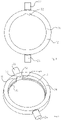
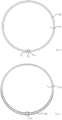
- Figures 1 and 2 show a holder 10, comprising a pot-shaped lower part that is open on the bottom side and an upper part 14, or cover, which is connectable thereto, for instance through screws, in an annular manner, to accommodate a disc-shaped blank 16 and to fix it so that it can be processed in a processing machine such as a milling machine through a CAD/CAM process for the production of a dental part, in particular a full denture.
- a processing machine such as a milling machine through a CAD/CAM process for the production of a dental part, in particular a full denture.
- an adapter 18 also referred to as a positioning aid, is used according to the invention.
- the adapter 18 brings about a positive connection between the blank 16 and the holder 10, so that the desired exact positioning and repositioning is ensured.
- the adapter 18 for instance made from PMMA, is designed in such a way that fixing in the holder 10 takes place by using an existing structural feature of the holder such as a recess or projection, so that changes to the holder itself are not required.
- the holder 10 described in the example consists of the lower part 12 which has a circumferential wall 20 that follows a hollow cylinder section from which diametrically opposite shaft stumps 22, 24, referred to as axes, project, which are used for attachment in a processing machine - hereinafter simply referred to as a milling machine.
- a substantially circumferential and inwardly-projecting web or flange 26 extends from the circumferential wall 20, onto which the blank 16 with a peripherally extending web or collar 28 is placed, which can be an integral component of the blank 16 itself or a separate element, which is connected to the blank 16, for instance through gluing.
- a recess 32 extends over the height of the circumferential wall 20 in the inner wall 30 of the circumferential wall 20 and is suitable for the insertion of an insert, not shown, into the lower part 12 of the holder 10, which can serve for example to hold individual blanks, as is known, for example, from WO 2016/153986 A1 .
- the recess 32 in the lower part 12 is provided for structural reasons.
- this recess 32 or another suitable structural design of the lower part 12 is used to positively hold the adapter 18 or a section thereof so that it is clearly positioned.
- a further section of the adapter 18 engages in a mechanical referencing device 34 to be formed in the blank 16, which in the example is designed as a groove extending in the axial direction of the blank 16.
- the adapter has an arcuate base section 36, which is adapted in the circumferential direction to the recess 32 and with respect to its boundaries 38, 40.
- the back surface 37 of the base portion 36 is adapted in its course to the base surface 39 of the recess 32.
- the distance between the side edges 42, 44 of the base part 36 corresponds to the distance between the edges 38, 40 of the recess 32.
- a projection 46 protrudes from the inner surface of the base part 36, the groove 36 of which is matched to the geometry so that the distance between the side edges 48, 50 of the projection 46 is equal to the distance of the side edges 52, 54 of the groove 34.
- flat-shaped sections 56, 58 in the form of an arc extend from the inner surface of the base section 36 and merge into the circumferential web or collar 28 on the upper side.
- the projections 56, 58 are not mandatory constructive features of the adapter 18.
- the blank 16 is inserted into the lower part 12 of the holder 10 without a positive connection being effected via the adapter 18. It can be seen from the drawing that the blank 16 can be inserted in virtually any desired position. Thus, it is not possible to ensure a predetermined, defined alignment between the blank 16 and the holder 10 or the lower part 12.
- the blank 16 can only be inserted into the lower part 12 in the position in which the groove 34 is aligned with the projection 46 and can penetrate into the groove 34.
- the blank 16 can be inserted into the holder 10 in a clear position and thus into the lower part 12.
- no other position can be assumed between the blank 16 and the lower part 12 of the holder 10 than that specified by the adapter 18.
- this is closed by means of the annular upper part 14 designated as the cover. In particular, the upper part 14 is screwed into the lower part 12.
- the adapter 18 in Fig. 7 is shown purely by way of example, without thereby limiting the invention.
- the adapter would have to bridge a section of the lower part 12, as will be explained with reference to Figures 11 to 13 .
- FIG. 11 A further embodiment of a holder 110 and an adapter 118 is shown in Figures 11 to 13 to enable a clear positioning and repositioning of a blank 116 in accordance with the teaching of the invention.
- the holder 110 comprises a lower part 112 in which a recess (not shown in the drawing) corresponding to the size of the blank 116 is present in order to provide the possibility that the blank 116 can be machined from both sides in a milling machine.
- the blank 116 is fixed in the holder 110 by means of a top part 114 designated as a clamping ring in the holder 110.
- the blank 116 rests with a circumferentially extending web or collar, as explained with reference to Figures 3 and 4 , on a corresponding shoulder of the lower part 112.
- the clamping ring 114 is fixed with the lower part 112 by means of screws, one of which is indicated by the reference number 115 by way of example only.
- corresponding oblong-shaped holes 117 are provided in the clamping ring 114 and have a clearance which is greater than the diameter of the head of the screw 115 in at least one section and is less than it in at least another section.
- oblong-shaped holes and the bore accessible therefrom are used to positively receive a section of the adapter 118.
- an oblong-shaped hole 119 with the bore 121 is used.
- a base section 136 of the adapter 118 is introduced into the oblong-shaped hole 119.
- the adapter 118 has a cuboid central part 138 with end-rounded sections 140, 142, as shown in the drawing for adaptation to the oblong-shaped hole 119.
- the base section 136 must be geometrically adapted to the geometry of the oblong-shaped hole 119 in such a way that movement is prevented in the radial direction of the clamping ring 114. In the longitudinal direction of the oblong-shaped hole 119 this is prevented by the fact that a pin-shaped projection 148, which is adapted to the internal geometry of the bore 121, protrudes from the base section 136.
- the projection 148 is adapted to the bore 121 in such a way that there is a positive engagement preventing, in principle, a relative movement.
- a cuboid projection 146 protrudes from the opposing flat side 150 of the base section 136, to which a mechanical referencing introduced in the blank 116 is adapted in the form of a groove 134 at least in sections so that a positive engagement of the projection 146 into the groove 134 is made possible.
- the adapter 118 is not inserted so that, as a result, the blank 116 can be fixed in any desired orientation to the holder 110. This possibility no longer exists if the adapter 118 on the one hand positively engages with the projection 148 into the bore 121 which is provided with an internal thread and, on the other hand, positively engages in the groove 134 with the projection 146.
- an implant blank 216 which can have a geometry which is the same as that of the blank 16.
- the implant blank has bores, some of which are identified by the reference numbers 218, 220 by way of example.
- the bores 218, 220 are geometrically adapted to the outer geometry of base elements of abutments. This is preferably a titanium base, on which a ceramic post is placed to form the abutment.
- the blank 216 is made from the corresponding material of the post, in particular zirconium dioxide.
- FIG. 14 An enlarged view of a section of the blank 216 is shown in the lower view in Fig. 14 .
- the blank 216 is provided with a mechanical referencing such as groove 234, as shown in the upper view in Fig. 14 .
- a mechanical referencing such as groove 234, as shown in the upper view in Fig. 14 .
Landscapes
- Health & Medical Sciences (AREA)
- General Health & Medical Sciences (AREA)
- Dentistry (AREA)
- Epidemiology (AREA)
- Life Sciences & Earth Sciences (AREA)
- Animal Behavior & Ethology (AREA)
- Oral & Maxillofacial Surgery (AREA)
- Public Health (AREA)
- Veterinary Medicine (AREA)
- Dental Prosthetics (AREA)
- Forging (AREA)
- Supporting Of Heads In Record-Carrier Devices (AREA)
- Adjustment Of The Magnetic Head Position Track Following On Tapes (AREA)
- Jigs For Machine Tools (AREA)
Claims (5)
- Verfahren zur Positionierung eines scheibenförmigen Rohlings (16, 116, 216), der nach dem Einsetzen in eine Halterung damit in Kontakt ist, wobei die Halterung (10, 110) ein Strukturelement (32, 119, 121), wie eine Vertiefung, wie eine Senkung oder einen Vorsprung, aufweist, wobei der Rohling (16, 116, 216) in der Halterung (10, 110) mittels eines Adapters (18, 118) positioniert ist, der sowohl in der Halterung (10, 110) als auch in dem Strukturelement (32, 119, 121) und dem Rohling (16, 116, 216) eingesetzt ist, wobei der Adapter formschlüssig mit der Halterung (10, 110) und dem Strukturelement (32, 119, 121) und mit dem Rohling (16, 116, 216) im Eingriff steht;wobei der Rohling (16, 116, 216) nach dem Positionieren in der Halterung (10, 110) verarbeitet, aus der Halterung entfernt und dann in der Halterung wieder mittels des Adapters (18, 118) positioniert wird;wobei der Rohling (16, 116, 216) mit einer mechanischen Referenzierung (34, 134), wie einer Vertiefung, wie einer Nut, versehen ist, die mit einem ersten Abschnitt (46, 146) des Adapters (18, 118) zum Positionieren des Rohlings in Wechselwirkung tritt, wobei der erste Abschnitt (46, 146) in die mechanische Referenzierung eindringt;und wobei zur eindeutigen Positionierung des Rohlings (16, 116, 216) der Adapter (18, 118) mit einem zweiten Abschnitt (36, 136) mit dem Strukturelement (34, 119, 121) in Wechselwirkung steht, und mit dem ersten Abschnitt (46, 146) mit der mechanischen Referenzierung (34, 134) des Rohlings in Wechselwirkung steht, wobei zwischen dem ersten Abschnitt und dem zweiten Abschnitt ein Abschnitt des Adapters (18, 118) einen Abschnitt der Halterung (10, 110) überbrückt.
- Verfahren nach Anspruch 1,
dadurch gekennzeichnet, dass
die Halterung (10, 110) den Rohling (16, 116, 216) ohne Vorsprung kontaktiert. - Verfahren zum Herstellen einer Prothese, insbesondere einer Vollprothese, das mindestens die folgenden Schritte umfasst- Positionieren eines scheibenförmigen Rohlings (16, 116, 216) in einer Halterung (10, 110),- Verarbeiten des Rohlings in einer Verarbeitungsmaschine,- Entfernen des Rohlings aus der Halterung und Bearbeiten des Rohlings außerhalb der Verarbeitungsmaschine,- Wiederpositionieren des Rohlings in der Halterung,- Wiederholen des Bearbeitens des Rohlings in der Verarbeitungsmaschine,dadurch gekennzeichnet, dass
sowohl das Positionieren als auch das Wiederpositionieren des Rohlings (16, 116, 216) in der Halterung (10, 110) mittels eines Adapters (18, 118) erfolgt, der sowohl mit der Halterung oder einem Element mit feststehender Position, das mit der Halterung verbunden ist, als auch mit einer mechanischen Referenzierung (34, 134), die in dem Rohling gebildet und an einen Abschnitt des Adapters angepasst ist, in Wechselwirkung tritt. - Verfahren nach mindestens einem der vorstehenden Ansprüche,
dadurch gekennzeichnet, dass
der Rohling (16, 116, 216) derart ist, dass seine Umfangsoberfläche oder ein Abschnitt der Umfangsoberfläche oder ein Element, das mit dem Rohling verbunden oder einstückig damit gebildet ist, wie ein Bund (28), bevorzugt umfänglich oder im Wesentlichen umfänglich mit der Halterung in Kontakt steht, die an die Umfangsoberfläche bzw. den Abschnitt anliegt. - Verfahren nach mindestens einem der vorstehenden Ansprüche,
dadurch gekennzeichnet, dass
der Rohling (16, 116, 216) ein Rohling ist, aus dem eine Zahnprothese oder Abschnitt eines Abutments erzeugt werden kann.
Applications Claiming Priority (1)
| Application Number | Priority Date | Filing Date | Title |
|---|---|---|---|
| PCT/EP2017/070003 WO2019029791A1 (en) | 2017-08-08 | 2017-08-08 | METHOD FOR POSITIONING A DRAFT |
Publications (2)
| Publication Number | Publication Date |
|---|---|
| EP3664744A1 EP3664744A1 (de) | 2020-06-17 |
| EP3664744B1 true EP3664744B1 (de) | 2023-03-08 |
Family
ID=59631755
Family Applications (1)
| Application Number | Title | Priority Date | Filing Date |
|---|---|---|---|
| EP17752353.7A Active EP3664744B1 (de) | 2017-08-08 | 2017-08-08 | Verfahren zur positionierung eines rohlings |
Country Status (5)
| Country | Link |
|---|---|
| EP (1) | EP3664744B1 (de) |
| JP (1) | JP7035165B2 (de) |
| CA (1) | CA3072372C (de) |
| ES (1) | ES2942852T3 (de) |
| WO (1) | WO2019029791A1 (de) |
Families Citing this family (2)
| Publication number | Priority date | Publication date | Assignee | Title |
|---|---|---|---|---|
| US10959817B2 (en) | 2019-08-14 | 2021-03-30 | Sdc U.S. Smilepay Spv | Dental model holding system |
| CN111444611B (zh) * | 2020-03-25 | 2023-04-07 | 东风汽车集团有限公司 | 基于enovia的毛坯件的编号和数模建立方法 |
Citations (1)
| Publication number | Priority date | Publication date | Assignee | Title |
|---|---|---|---|---|
| EP3372192A1 (de) * | 2017-03-10 | 2018-09-12 | Johannes Petrus Michael Grobbee | Zahnrohlingpositionierungsvorrichtung |
Family Cites Families (8)
| Publication number | Priority date | Publication date | Assignee | Title |
|---|---|---|---|---|
| CH665551A5 (de) | 1984-03-06 | 1988-05-31 | Werner Hans Dr Med De Moermann | Rohling zur herstellung zahntechnischer formteile. |
| US6482284B1 (en) | 2000-08-31 | 2002-11-19 | 3M Innovative Properties Company | Method of making a dental mill blank and support stub assembly |
| DE20316004U1 (de) | 2003-10-14 | 2004-03-04 | Stührenberg, Birgit | Rohling für die Herstellung von Zahnersatz |
| DE102007043837B4 (de) | 2007-09-14 | 2014-02-13 | Ivoclar Vivadent Ag | Rohlinganordnung |
| DE202012008015U1 (de) * | 2012-08-23 | 2012-12-12 | Doceram Gmbh | Halter für Rohlinge |
| DE102014117109A1 (de) * | 2014-11-21 | 2016-05-25 | Merz Dental Gmbh | Verfahren zur Lagepositionierung eines Halbzeuges, Verfahren zur Herstellung eines Halbzeuges zur reproduzierbaren Lagepositionierung sowie ein geeignetes Halbzeug und eine entsprechende Verwendung hierfür |
| US10010386B2 (en) | 2015-03-24 | 2018-07-03 | Ivoclar Vivadent Ag | Dental blank holder |
| AT516840B1 (de) * | 2015-04-30 | 2016-09-15 | Steger Heinrich | Rohling zur Herstellung eines Dentalelements |
-
2017
- 2017-08-08 EP EP17752353.7A patent/EP3664744B1/de active Active
- 2017-08-08 WO PCT/EP2017/070003 patent/WO2019029791A1/en not_active Ceased
- 2017-08-08 ES ES17752353T patent/ES2942852T3/es active Active
- 2017-08-08 CA CA3072372A patent/CA3072372C/en active Active
- 2017-08-08 JP JP2020507105A patent/JP7035165B2/ja active Active
Patent Citations (1)
| Publication number | Priority date | Publication date | Assignee | Title |
|---|---|---|---|---|
| EP3372192A1 (de) * | 2017-03-10 | 2018-09-12 | Johannes Petrus Michael Grobbee | Zahnrohlingpositionierungsvorrichtung |
Also Published As
| Publication number | Publication date |
|---|---|
| EP3664744A1 (de) | 2020-06-17 |
| CA3072372C (en) | 2023-06-27 |
| ES2942852T3 (es) | 2023-06-07 |
| CA3072372A1 (en) | 2019-02-14 |
| JP2020531069A (ja) | 2020-11-05 |
| JP7035165B2 (ja) | 2022-03-14 |
| WO2019029791A1 (en) | 2019-02-14 |
Similar Documents
| Publication | Publication Date | Title |
|---|---|---|
| US10799326B2 (en) | Method for the positioning of a blank | |
| EP3380036B1 (de) | Platte zur herstellung eines zahnimplantats und/oder einer künstlichen prothese | |
| US8622377B2 (en) | Holder for CAD/CAM blanks | |
| US7789601B2 (en) | Mill blank mandrel | |
| US9060831B2 (en) | Device for producing a dental workpiece | |
| EP3117794B1 (de) | Zahnimplantat prothesenstruktur | |
| US20180353269A1 (en) | Interface element for dental prostheses | |
| EP3868332B1 (de) | Fräsadapter | |
| US20150099243A1 (en) | Axially elongate dental machining portion | |
| KR20140018884A (ko) | 의치 시스템 | |
| US20080254413A1 (en) | Process for the production of a head piece of a tooth implant and manufacturing kit for such a process | |
| US11224919B2 (en) | Method for correcting an axial position of a workpiece support | |
| EP3664744B1 (de) | Verfahren zur positionierung eines rohlings | |
| US20170056134A1 (en) | Dental abutments and associated systems and methods | |
| EP3641695B1 (de) | Montageelement zur herstellung einer zahnprothese, prothese und herstellungsverfahren dafür | |
| US11839941B2 (en) | Holding device for an abutment blank | |
| JP2007222225A (ja) | 連結体及びそれを用いた歯科用補綴物の作製方法 | |
| CA3005382C (en) | Plate for production of a dental implant and/or artificial prosthesis | |
| KR101249515B1 (ko) | 어버트먼트 소재 및 이를 이용한 가공방법 | |
| CN112689484A (zh) | 用于生产牙齿假体的坯件及其制造方法 |
Legal Events
| Date | Code | Title | Description |
|---|---|---|---|
| STAA | Information on the status of an ep patent application or granted ep patent |
Free format text: STATUS: UNKNOWN |
|
| STAA | Information on the status of an ep patent application or granted ep patent |
Free format text: STATUS: THE INTERNATIONAL PUBLICATION HAS BEEN MADE |
|
| PUAI | Public reference made under article 153(3) epc to a published international application that has entered the european phase |
Free format text: ORIGINAL CODE: 0009012 |
|
| STAA | Information on the status of an ep patent application or granted ep patent |
Free format text: STATUS: REQUEST FOR EXAMINATION WAS MADE |
|
| 17P | Request for examination filed |
Effective date: 20200213 |
|
| AK | Designated contracting states |
Kind code of ref document: A1 Designated state(s): AL AT BE BG CH CY CZ DE DK EE ES FI FR GB GR HR HU IE IS IT LI LT LU LV MC MK MT NL NO PL PT RO RS SE SI SK SM TR |
|
| AX | Request for extension of the european patent |
Extension state: BA ME |
|
| RIN1 | Information on inventor provided before grant (corrected) |
Inventor name: GEBHARDT, ANDREAS Inventor name: VOELKL, LOTHAR Inventor name: FECHER, STEFAN |
|
| DAV | Request for validation of the european patent (deleted) | ||
| DAX | Request for extension of the european patent (deleted) | ||
| STAA | Information on the status of an ep patent application or granted ep patent |
Free format text: STATUS: EXAMINATION IS IN PROGRESS |
|
| 17Q | First examination report despatched |
Effective date: 20210503 |
|
| REG | Reference to a national code |
Ref country code: DE Ref legal event code: R079 Ref document number: 602017066632 Country of ref document: DE Free format text: PREVIOUS MAIN CLASS: A61C0013000000 Ipc: B23Q0003000000 |
|
| GRAP | Despatch of communication of intention to grant a patent |
Free format text: ORIGINAL CODE: EPIDOSNIGR1 |
|
| STAA | Information on the status of an ep patent application or granted ep patent |
Free format text: STATUS: GRANT OF PATENT IS INTENDED |
|
| RIC1 | Information provided on ipc code assigned before grant |
Ipc: B23Q 3/00 20060101AFI20220901BHEP |
|
| INTG | Intention to grant announced |
Effective date: 20221005 |
|
| GRAS | Grant fee paid |
Free format text: ORIGINAL CODE: EPIDOSNIGR3 |
|
| GRAA | (expected) grant |
Free format text: ORIGINAL CODE: 0009210 |
|
| STAA | Information on the status of an ep patent application or granted ep patent |
Free format text: STATUS: THE PATENT HAS BEEN GRANTED |
|
| AK | Designated contracting states |
Kind code of ref document: B1 Designated state(s): AL AT BE BG CH CY CZ DE DK EE ES FI FR GB GR HR HU IE IS IT LI LT LU LV MC MK MT NL NO PL PT RO RS SE SI SK SM TR |
|
| REG | Reference to a national code |
Ref country code: GB Ref legal event code: FG4D |
|
| REG | Reference to a national code |
Ref country code: CH Ref legal event code: EP Ref country code: AT Ref legal event code: REF Ref document number: 1552259 Country of ref document: AT Kind code of ref document: T Effective date: 20230315 |
|
| REG | Reference to a national code |
Ref country code: DE Ref legal event code: R096 Ref document number: 602017066632 Country of ref document: DE |
|
| REG | Reference to a national code |
Ref country code: IE Ref legal event code: FG4D |
|
| REG | Reference to a national code |
Ref country code: NL Ref legal event code: FP |
|
| REG | Reference to a national code |
Ref country code: ES Ref legal event code: FG2A Ref document number: 2942852 Country of ref document: ES Kind code of ref document: T3 Effective date: 20230607 |
|
| P01 | Opt-out of the competence of the unified patent court (upc) registered |
Effective date: 20230509 |
|
| REG | Reference to a national code |
Ref country code: LT Ref legal event code: MG9D |
|
| PG25 | Lapsed in a contracting state [announced via postgrant information from national office to epo] |
Ref country code: RS Free format text: LAPSE BECAUSE OF FAILURE TO SUBMIT A TRANSLATION OF THE DESCRIPTION OR TO PAY THE FEE WITHIN THE PRESCRIBED TIME-LIMIT Effective date: 20230308 Ref country code: NO Free format text: LAPSE BECAUSE OF FAILURE TO SUBMIT A TRANSLATION OF THE DESCRIPTION OR TO PAY THE FEE WITHIN THE PRESCRIBED TIME-LIMIT Effective date: 20230608 Ref country code: LV Free format text: LAPSE BECAUSE OF FAILURE TO SUBMIT A TRANSLATION OF THE DESCRIPTION OR TO PAY THE FEE WITHIN THE PRESCRIBED TIME-LIMIT Effective date: 20230308 Ref country code: LT Free format text: LAPSE BECAUSE OF FAILURE TO SUBMIT A TRANSLATION OF THE DESCRIPTION OR TO PAY THE FEE WITHIN THE PRESCRIBED TIME-LIMIT Effective date: 20230308 Ref country code: HR Free format text: LAPSE BECAUSE OF FAILURE TO SUBMIT A TRANSLATION OF THE DESCRIPTION OR TO PAY THE FEE WITHIN THE PRESCRIBED TIME-LIMIT Effective date: 20230308 |
|
| PG25 | Lapsed in a contracting state [announced via postgrant information from national office to epo] |
Ref country code: SE Free format text: LAPSE BECAUSE OF FAILURE TO SUBMIT A TRANSLATION OF THE DESCRIPTION OR TO PAY THE FEE WITHIN THE PRESCRIBED TIME-LIMIT Effective date: 20230308 Ref country code: GR Free format text: LAPSE BECAUSE OF FAILURE TO SUBMIT A TRANSLATION OF THE DESCRIPTION OR TO PAY THE FEE WITHIN THE PRESCRIBED TIME-LIMIT Effective date: 20230609 Ref country code: FI Free format text: LAPSE BECAUSE OF FAILURE TO SUBMIT A TRANSLATION OF THE DESCRIPTION OR TO PAY THE FEE WITHIN THE PRESCRIBED TIME-LIMIT Effective date: 20230308 |
|
| PG25 | Lapsed in a contracting state [announced via postgrant information from national office to epo] |
Ref country code: SM Free format text: LAPSE BECAUSE OF FAILURE TO SUBMIT A TRANSLATION OF THE DESCRIPTION OR TO PAY THE FEE WITHIN THE PRESCRIBED TIME-LIMIT Effective date: 20230308 Ref country code: RO Free format text: LAPSE BECAUSE OF FAILURE TO SUBMIT A TRANSLATION OF THE DESCRIPTION OR TO PAY THE FEE WITHIN THE PRESCRIBED TIME-LIMIT Effective date: 20230308 Ref country code: PT Free format text: LAPSE BECAUSE OF FAILURE TO SUBMIT A TRANSLATION OF THE DESCRIPTION OR TO PAY THE FEE WITHIN THE PRESCRIBED TIME-LIMIT Effective date: 20230710 Ref country code: EE Free format text: LAPSE BECAUSE OF FAILURE TO SUBMIT A TRANSLATION OF THE DESCRIPTION OR TO PAY THE FEE WITHIN THE PRESCRIBED TIME-LIMIT Effective date: 20230308 Ref country code: CZ Free format text: LAPSE BECAUSE OF FAILURE TO SUBMIT A TRANSLATION OF THE DESCRIPTION OR TO PAY THE FEE WITHIN THE PRESCRIBED TIME-LIMIT Effective date: 20230308 |
|
| PG25 | Lapsed in a contracting state [announced via postgrant information from national office to epo] |
Ref country code: SK Free format text: LAPSE BECAUSE OF FAILURE TO SUBMIT A TRANSLATION OF THE DESCRIPTION OR TO PAY THE FEE WITHIN THE PRESCRIBED TIME-LIMIT Effective date: 20230308 Ref country code: PL Free format text: LAPSE BECAUSE OF FAILURE TO SUBMIT A TRANSLATION OF THE DESCRIPTION OR TO PAY THE FEE WITHIN THE PRESCRIBED TIME-LIMIT Effective date: 20230308 Ref country code: IS Free format text: LAPSE BECAUSE OF FAILURE TO SUBMIT A TRANSLATION OF THE DESCRIPTION OR TO PAY THE FEE WITHIN THE PRESCRIBED TIME-LIMIT Effective date: 20230708 |
|
| REG | Reference to a national code |
Ref country code: DE Ref legal event code: R097 Ref document number: 602017066632 Country of ref document: DE |
|
| PLBE | No opposition filed within time limit |
Free format text: ORIGINAL CODE: 0009261 |
|
| STAA | Information on the status of an ep patent application or granted ep patent |
Free format text: STATUS: NO OPPOSITION FILED WITHIN TIME LIMIT |
|
| PG25 | Lapsed in a contracting state [announced via postgrant information from national office to epo] |
Ref country code: SI Free format text: LAPSE BECAUSE OF FAILURE TO SUBMIT A TRANSLATION OF THE DESCRIPTION OR TO PAY THE FEE WITHIN THE PRESCRIBED TIME-LIMIT Effective date: 20230308 Ref country code: DK Free format text: LAPSE BECAUSE OF FAILURE TO SUBMIT A TRANSLATION OF THE DESCRIPTION OR TO PAY THE FEE WITHIN THE PRESCRIBED TIME-LIMIT Effective date: 20230308 |
|
| 26N | No opposition filed |
Effective date: 20231211 |
|
| REG | Reference to a national code |
Ref country code: AT Ref legal event code: UEP Ref document number: 1552259 Country of ref document: AT Kind code of ref document: T Effective date: 20230308 |
|
| PG25 | Lapsed in a contracting state [announced via postgrant information from national office to epo] |
Ref country code: MC Free format text: LAPSE BECAUSE OF FAILURE TO SUBMIT A TRANSLATION OF THE DESCRIPTION OR TO PAY THE FEE WITHIN THE PRESCRIBED TIME-LIMIT Effective date: 20230308 |
|
| PG25 | Lapsed in a contracting state [announced via postgrant information from national office to epo] |
Ref country code: MC Free format text: LAPSE BECAUSE OF FAILURE TO SUBMIT A TRANSLATION OF THE DESCRIPTION OR TO PAY THE FEE WITHIN THE PRESCRIBED TIME-LIMIT Effective date: 20230308 |
|
| PG25 | Lapsed in a contracting state [announced via postgrant information from national office to epo] |
Ref country code: LU Free format text: LAPSE BECAUSE OF NON-PAYMENT OF DUE FEES Effective date: 20230808 |
|
| GBPC | Gb: european patent ceased through non-payment of renewal fee |
Effective date: 20230808 |
|
| PG25 | Lapsed in a contracting state [announced via postgrant information from national office to epo] |
Ref country code: LU Free format text: LAPSE BECAUSE OF NON-PAYMENT OF DUE FEES Effective date: 20230808 |
|
| REG | Reference to a national code |
Ref country code: BE Ref legal event code: MM Effective date: 20230831 |
|
| REG | Reference to a national code |
Ref country code: IE Ref legal event code: MM4A |
|
| PG25 | Lapsed in a contracting state [announced via postgrant information from national office to epo] |
Ref country code: IE Free format text: LAPSE BECAUSE OF NON-PAYMENT OF DUE FEES Effective date: 20230808 |
|
| PG25 | Lapsed in a contracting state [announced via postgrant information from national office to epo] |
Ref country code: GB Free format text: LAPSE BECAUSE OF NON-PAYMENT OF DUE FEES Effective date: 20230808 |
|
| PG25 | Lapsed in a contracting state [announced via postgrant information from national office to epo] |
Ref country code: IE Free format text: LAPSE BECAUSE OF NON-PAYMENT OF DUE FEES Effective date: 20230808 Ref country code: GB Free format text: LAPSE BECAUSE OF NON-PAYMENT OF DUE FEES Effective date: 20230808 |
|
| PG25 | Lapsed in a contracting state [announced via postgrant information from national office to epo] |
Ref country code: BE Free format text: LAPSE BECAUSE OF NON-PAYMENT OF DUE FEES Effective date: 20230831 |
|
| PGFP | Annual fee paid to national office [announced via postgrant information from national office to epo] |
Ref country code: NL Payment date: 20240705 Year of fee payment: 8 |
|
| PGFP | Annual fee paid to national office [announced via postgrant information from national office to epo] |
Ref country code: AT Payment date: 20240725 Year of fee payment: 8 |
|
| PG25 | Lapsed in a contracting state [announced via postgrant information from national office to epo] |
Ref country code: BG Free format text: LAPSE BECAUSE OF FAILURE TO SUBMIT A TRANSLATION OF THE DESCRIPTION OR TO PAY THE FEE WITHIN THE PRESCRIBED TIME-LIMIT Effective date: 20230308 |
|
| PG25 | Lapsed in a contracting state [announced via postgrant information from national office to epo] |
Ref country code: BG Free format text: LAPSE BECAUSE OF FAILURE TO SUBMIT A TRANSLATION OF THE DESCRIPTION OR TO PAY THE FEE WITHIN THE PRESCRIBED TIME-LIMIT Effective date: 20230308 |
|
| PG25 | Lapsed in a contracting state [announced via postgrant information from national office to epo] |
Ref country code: CY Free format text: LAPSE BECAUSE OF FAILURE TO SUBMIT A TRANSLATION OF THE DESCRIPTION OR TO PAY THE FEE WITHIN THE PRESCRIBED TIME-LIMIT; INVALID AB INITIO Effective date: 20170808 |
|
| PG25 | Lapsed in a contracting state [announced via postgrant information from national office to epo] |
Ref country code: HU Free format text: LAPSE BECAUSE OF FAILURE TO SUBMIT A TRANSLATION OF THE DESCRIPTION OR TO PAY THE FEE WITHIN THE PRESCRIBED TIME-LIMIT; INVALID AB INITIO Effective date: 20170808 |
|
| PGFP | Annual fee paid to national office [announced via postgrant information from national office to epo] |
Ref country code: ES Payment date: 20250901 Year of fee payment: 9 |
|
| PGFP | Annual fee paid to national office [announced via postgrant information from national office to epo] |
Ref country code: DE Payment date: 20250724 Year of fee payment: 9 |
|
| PGFP | Annual fee paid to national office [announced via postgrant information from national office to epo] |
Ref country code: IT Payment date: 20250723 Year of fee payment: 9 |
|
| PGFP | Annual fee paid to national office [announced via postgrant information from national office to epo] |
Ref country code: FR Payment date: 20250725 Year of fee payment: 9 |
|
| PGFP | Annual fee paid to national office [announced via postgrant information from national office to epo] |
Ref country code: CH Payment date: 20250901 Year of fee payment: 9 |
|
| PG25 | Lapsed in a contracting state [announced via postgrant information from national office to epo] |
Ref country code: TR Free format text: LAPSE BECAUSE OF FAILURE TO SUBMIT A TRANSLATION OF THE DESCRIPTION OR TO PAY THE FEE WITHIN THE PRESCRIBED TIME-LIMIT Effective date: 20230308 |
|
| REG | Reference to a national code |
Ref country code: NL Ref legal event code: MM Effective date: 20250901 |
|
| PG25 | Lapsed in a contracting state [announced via postgrant information from national office to epo] |
Ref country code: AT Free format text: LAPSE BECAUSE OF NON-PAYMENT OF DUE FEES Effective date: 20250808 |
|
| REG | Reference to a national code |
Ref country code: AT Ref legal event code: MM01 Ref document number: 1552259 Country of ref document: AT Kind code of ref document: T Effective date: 20250808 |