EP3664876B1 - Pulmonale freisetzungsvorrichtungen - Google Patents
Pulmonale freisetzungsvorrichtungen Download PDFInfo
- Publication number
- EP3664876B1 EP3664876B1 EP18762921.7A EP18762921A EP3664876B1 EP 3664876 B1 EP3664876 B1 EP 3664876B1 EP 18762921 A EP18762921 A EP 18762921A EP 3664876 B1 EP3664876 B1 EP 3664876B1
- Authority
- EP
- European Patent Office
- Prior art keywords
- chamber
- mouthpiece
- pulmonary delivery
- delivery device
- air inlets
- Prior art date
- Legal status (The legal status is an assumption and is not a legal conclusion. Google has not performed a legal analysis and makes no representation as to the accuracy of the status listed.)
- Active
Links
Images




Classifications
-
- A—HUMAN NECESSITIES
- A24—TOBACCO; CIGARS; CIGARETTES; SIMULATED SMOKING DEVICES; SMOKERS' REQUISITES
- A24F—SMOKERS' REQUISITES; MATCH BOXES; SIMULATED SMOKING DEVICES
- A24F40/00—Electrically operated smoking devices; Component parts thereof; Manufacture thereof; Maintenance or testing thereof; Charging means specially adapted therefor
- A24F40/30—Devices using two or more structurally separated inhalable precursors, e.g. using two liquid precursors in two cartridges
-
- A—HUMAN NECESSITIES
- A24—TOBACCO; CIGARS; CIGARETTES; SIMULATED SMOKING DEVICES; SMOKERS' REQUISITES
- A24F—SMOKERS' REQUISITES; MATCH BOXES; SIMULATED SMOKING DEVICES
- A24F40/00—Electrically operated smoking devices; Component parts thereof; Manufacture thereof; Maintenance or testing thereof; Charging means specially adapted therefor
- A24F40/40—Constructional details, e.g. connection of cartridges and battery parts
- A24F40/42—Cartridges or containers for inhalable precursors
-
- A—HUMAN NECESSITIES
- A24—TOBACCO; CIGARS; CIGARETTES; SIMULATED SMOKING DEVICES; SMOKERS' REQUISITES
- A24F—SMOKERS' REQUISITES; MATCH BOXES; SIMULATED SMOKING DEVICES
- A24F40/00—Electrically operated smoking devices; Component parts thereof; Manufacture thereof; Maintenance or testing thereof; Charging means specially adapted therefor
- A24F40/40—Constructional details, e.g. connection of cartridges and battery parts
- A24F40/48—Fluid transfer means, e.g. pumps
-
- A—HUMAN NECESSITIES
- A24—TOBACCO; CIGARS; CIGARETTES; SIMULATED SMOKING DEVICES; SMOKERS' REQUISITES
- A24F—SMOKERS' REQUISITES; MATCH BOXES; SIMULATED SMOKING DEVICES
- A24F40/00—Electrically operated smoking devices; Component parts thereof; Manufacture thereof; Maintenance or testing thereof; Charging means specially adapted therefor
- A24F40/40—Constructional details, e.g. connection of cartridges and battery parts
- A24F40/48—Fluid transfer means, e.g. pumps
- A24F40/485—Valves; Apertures
-
- A—HUMAN NECESSITIES
- A61—MEDICAL OR VETERINARY SCIENCE; HYGIENE
- A61M—DEVICES FOR INTRODUCING MEDIA INTO, OR ONTO, THE BODY; DEVICES FOR TRANSDUCING BODY MEDIA OR FOR TAKING MEDIA FROM THE BODY; DEVICES FOR PRODUCING OR ENDING SLEEP OR STUPOR
- A61M11/00—Sprayers or atomisers specially adapted for therapeutic purposes
-
- A—HUMAN NECESSITIES
- A61—MEDICAL OR VETERINARY SCIENCE; HYGIENE
- A61M—DEVICES FOR INTRODUCING MEDIA INTO, OR ONTO, THE BODY; DEVICES FOR TRANSDUCING BODY MEDIA OR FOR TAKING MEDIA FROM THE BODY; DEVICES FOR PRODUCING OR ENDING SLEEP OR STUPOR
- A61M11/00—Sprayers or atomisers specially adapted for therapeutic purposes
- A61M11/02—Sprayers or atomisers specially adapted for therapeutic purposes operated by air or other gas pressure applied to the liquid or other product to be sprayed or atomised
-
- A—HUMAN NECESSITIES
- A61—MEDICAL OR VETERINARY SCIENCE; HYGIENE
- A61M—DEVICES FOR INTRODUCING MEDIA INTO, OR ONTO, THE BODY; DEVICES FOR TRANSDUCING BODY MEDIA OR FOR TAKING MEDIA FROM THE BODY; DEVICES FOR PRODUCING OR ENDING SLEEP OR STUPOR
- A61M11/00—Sprayers or atomisers specially adapted for therapeutic purposes
- A61M11/04—Sprayers or atomisers specially adapted for therapeutic purposes operated by the vapour pressure of the liquid to be sprayed or atomised
- A61M11/041—Sprayers or atomisers specially adapted for therapeutic purposes operated by the vapour pressure of the liquid to be sprayed or atomised using heaters
-
- A—HUMAN NECESSITIES
- A61—MEDICAL OR VETERINARY SCIENCE; HYGIENE
- A61M—DEVICES FOR INTRODUCING MEDIA INTO, OR ONTO, THE BODY; DEVICES FOR TRANSDUCING BODY MEDIA OR FOR TAKING MEDIA FROM THE BODY; DEVICES FOR PRODUCING OR ENDING SLEEP OR STUPOR
- A61M11/00—Sprayers or atomisers specially adapted for therapeutic purposes
- A61M11/04—Sprayers or atomisers specially adapted for therapeutic purposes operated by the vapour pressure of the liquid to be sprayed or atomised
- A61M11/041—Sprayers or atomisers specially adapted for therapeutic purposes operated by the vapour pressure of the liquid to be sprayed or atomised using heaters
- A61M11/042—Sprayers or atomisers specially adapted for therapeutic purposes operated by the vapour pressure of the liquid to be sprayed or atomised using heaters electrical
-
- A—HUMAN NECESSITIES
- A61—MEDICAL OR VETERINARY SCIENCE; HYGIENE
- A61M—DEVICES FOR INTRODUCING MEDIA INTO, OR ONTO, THE BODY; DEVICES FOR TRANSDUCING BODY MEDIA OR FOR TAKING MEDIA FROM THE BODY; DEVICES FOR PRODUCING OR ENDING SLEEP OR STUPOR
- A61M15/00—Inhalators
-
- A—HUMAN NECESSITIES
- A24—TOBACCO; CIGARS; CIGARETTES; SIMULATED SMOKING DEVICES; SMOKERS' REQUISITES
- A24F—SMOKERS' REQUISITES; MATCH BOXES; SIMULATED SMOKING DEVICES
- A24F40/00—Electrically operated smoking devices; Component parts thereof; Manufacture thereof; Maintenance or testing thereof; Charging means specially adapted therefor
- A24F40/05—Devices without heating means
-
- A—HUMAN NECESSITIES
- A24—TOBACCO; CIGARS; CIGARETTES; SIMULATED SMOKING DEVICES; SMOKERS' REQUISITES
- A24F—SMOKERS' REQUISITES; MATCH BOXES; SIMULATED SMOKING DEVICES
- A24F40/00—Electrically operated smoking devices; Component parts thereof; Manufacture thereof; Maintenance or testing thereof; Charging means specially adapted therefor
- A24F40/10—Devices using liquid inhalable precursors
-
- A—HUMAN NECESSITIES
- A24—TOBACCO; CIGARS; CIGARETTES; SIMULATED SMOKING DEVICES; SMOKERS' REQUISITES
- A24F—SMOKERS' REQUISITES; MATCH BOXES; SIMULATED SMOKING DEVICES
- A24F40/00—Electrically operated smoking devices; Component parts thereof; Manufacture thereof; Maintenance or testing thereof; Charging means specially adapted therefor
- A24F40/20—Devices using solid inhalable precursors
-
- A—HUMAN NECESSITIES
- A24—TOBACCO; CIGARS; CIGARETTES; SIMULATED SMOKING DEVICES; SMOKERS' REQUISITES
- A24F—SMOKERS' REQUISITES; MATCH BOXES; SIMULATED SMOKING DEVICES
- A24F40/00—Electrically operated smoking devices; Component parts thereof; Manufacture thereof; Maintenance or testing thereof; Charging means specially adapted therefor
- A24F40/40—Constructional details, e.g. connection of cartridges and battery parts
- A24F40/46—Shape or structure of electric heating means
Definitions
- This disclosure relates to pulmonary delivery devices, particularly but not exclusively, to pulmonary delivery devices suitable for delivering active molecules and/or medicaments to users, such as nicotine, cannabinoid, peptides, proteins and other lung deliverable medicaments and other vape products.
- Pulmonary delivery devices have widespread uses in modern medicine as they enable drugs and medicaments to be delivered directly to the user's lungs. Moreover, as medicaments delivered to the lungs enter the bloodstream directly, rather than via the body's metabolism, as is the case with oral delivery systems, the benefits of the medicament, especially in pain relief or drug-weaning applications, are felt by the user almost immediately. Another major benefit of pulmonary delivery devices is their ability to deliver drugs without the use of needles.
- Existing pulmonary delivery systems take various forms, including inhalator sprays, nebulisers, metered dose inhalers in which the medication is administered in the form of a mist inhaled by the lungs and vapour delivery systems whereby the medicament is admixed to an inhalable vapour (often a water-containing vapour).
- a vapour type pulmonary delivery system comprises a carrier liquid, often water or a water-glycol mixture (the glycol serving to stabilise the water droplets when in the vapour form) to which is admixed a desired medicament.
- the carrier liquid can be vaporised in various ways, such as by spraying it through a nozzle, but in many cases, it is simply heated to form a vapour comprising the carrier liquid and the desired medicament.
- the resultant vapour is then inhaled by a user to deliver the medicament.
- heating of the medicament can result in undesirable by-products being formed and thus, inhaled by the user. This may also reduce the accuracy of the dose of medicament inhaled.
- vapour type pulmonary delivery system is an e-cigarette that vapes nicotine for inhalation by the user.
- a nicotine solution (“e-liquid") is provided in a reservoir (often in the form of a detachable cartridge) and passes along a wick to a heating element where it is vaporised and can be inhaled by the user.
- a length of resistance wire connected to a power source such as a battery, is coiled around the wick. When activated the wire heats up, turning the e-liquid to vapour which is then inhaled by the user.
- a power source such as a battery
- An alternative type of e-cigarette is an atomizer inhaler.
- This type of device provides a better, more rapid absorption of nicotine due to the use of a cold, pressurized vapour in place of a heated vapour, thereby avoiding significant condensation of the vapour in the mucosa of the nose and throat.
- the cold and dry sensation provided by this type of device results in the overall experience differing greatly to smoking conventional cigarettes resulting in such devices being less popular than the vaping type e-cigarettes, resulting in none or poor compliance.
- the Applicant's co-pending PCT Patent Publication No. WO 2015/079197 provides a solution to this problem by the provision of a first chamber having a heat source adapted to thermally vaporise a quantity of a carrier liquid to form a heated first vapour and a second chamber adapted to atomize a quantity of a second liquid containing an active molecule or medicament without heating of the second liquid to form a mist of a second vapour having a lower temperature than the first vapour, and an outlet via which, in use, a user can inhale a mixture of the first and second vapours.
- ETS Electronic nicotine delivery systems
- flavours in conjunction with the vaporised nicotine.
- Coffee, tobacco, mint and fruit flavours are often difficult to alternate due to their characteristic aromas.
- the flavours form an integral part of the propylene glycol/ water carrier liquid which contaminates the main body of the device.
- Patent document WO2015/079197A1 is hereby acknowledged .
- the present technology provides a pulmonary delivery device comprising: a first chamber adapted to thermally vaporise a quantity of a first fluid to form a relatively warm, wet first vapour; a second chamber adapted to atomize a quantity of a second fluid without heating of the second fluid to form a mist of a relatively cold, second vapour, and an outlet via which, in use, a user can inhale a mixture of the first and second vapours characterised in that the device incorporates a mouthpiece connectable to the outlet of the first chamber to provide an extension to the first chamber, the mouthpiece providing the second chamber in the form of a passive atomiser wherein the second chamber has at least one air inlet and is selectively or continuously in fluid communication with air, the second chamber including at least one flavouring or aroma and optionally an active molecule or medicament wherein the flavour/aroma and optional other active molecule or medicament are inhaled by drawing air through the second chamber.
- the flavourings and/or aroma may be selected from essential oils of dried flowers, buds, leaves, stems, fruit, seeds, peel, bark, or root e g oil of peppermint, spearmint, eucalyptus, wintergreen, clove, cardamom, cinnamon, bitter almond, coriander, caraway, ginger, juniper, orange, bitter orange, lemon, grapefruit, bergamot, thyme, fennel rosemary etc., natural flavors and aroma agents of essential oils or concentrates of flavor components with natural origin from e g fruits, berries, nuts, spices, mints, tobacco, cocoa, coffee, tea, vanilla, liquorice, caramel, toffee, honey, wine, liquors and brews, synthetic flavors and aroma agents consisting of mixtures of chemicals comprising hydrocarbons, alcohols, aldehydes, esters, ketones, ethers and oxides blended to match the natural flavor of e g fruits, berries, nuts, spices, mints, tobacco, cocoa, coffee, tea, vanilla, liquor
- the first chamber is provided with, or connected to, a heat source for vaporisation of the first fluid thereby creating a first "warm” vapour.
- the active molecule or medicament is included in the second fluid forming a "cold” vapour". In this manner, rapid absorption of an active molecule contained in the second vapour is achieved while providing the user with a desirable heat sensation on inhalation provided by the vapour of the "warm” first fluid.
- the active molecule or medicament may be included in the first fluid, forming a "hot vapour".
- the first fluid may comprise a carrier liquid (i.e. a liquid capable of forming a stable vapour), which may be an inert (non-medicated carrier liquid), such as water, or a water-glycol mixture.
- a carrier liquid i.e. a liquid capable of forming a stable vapour
- an inert non-medicated carrier liquid
- water such as water, or a water-glycol mixture.
- the flavour is provided in a solid or semi-solid form within the second chamber in a suitable formulation.
- the volume of air inhaled through the second chamber is selectively adjustable thereby enabling the amount of flavour inhaled to be varied and deposited in the mouth to enhance the flavour and avoid thermal decomposition thus avoiding carcinogenic degradant products.
- the device is provided with an outlet in the form of a mouthpiece, preferably being reversibly detachable, from the first and/or second chambers.
- the flavour may be provided in the mouthpiece to enable its easy replacement, for example to change to a different flavour or to allow replenishment of the flavour.
- the mouthpiece preferably comprises first and second mouthpiece chambers.
- the flavour preferably being in solid or semi-solid form, is provided in the second mouthpiece chamber.
- the mouthpiece comprises a central first mouthpiece chamber and a concentric outer second mouthpiece chamber, the second chamber having at least one air inlet.
- a flavour block is provided in the second chamber.
- the pulmonary delivery device includes only the first chamber with the mouthpiece providing the second chamber, the mouthpiece providing an extension to the first chamber in addition to providing the second chamber that preferably surrounds the extension to the first chamber.
- the central first chamber of the mouthpiece is dimensioned for receipt within a main first chamber provided in a pulmonary delivery device that produces heated or warm vapour.
- Suitable attachment means is provided for attachment of the mouthpiece to the main device.
- the end of the first mouthpiece chamber may be threaded or comprise a snap-fit arrangement.
- the outer second mouthpiece chamber may terminate in a flange having at least one air inlet wherein the flange is received on a top surface of the main first chamber of the main body of the pulmonary delivery device.
- multiple air inlets are provided at spaced apart intervals, preferably being equidistance apart, at the base of the second chamber. This provides control for optimized airflow for controlled or no flavour delivery.
- annular flange may extend laterally from a region of the first mouthpiece chamber that contacts that the main body of the device, the flange being provided with holes to allow air into the second mouthpiece chamber surrounding the first chamber.
- the entry of air through the inlets may be controllable and/or variable.
- the number of air inlets that are open may be adjustable to suit the preference of the user. Any suitable mechanism may be employed to allow opening and closing of one or more of the multiple inlets.
- the mouthpiece may comprise two parts, one part forming the central first chamber, at least a portion of the first chamber including air inlets in fluid communication with a second chamber formed by a second part surrounding the first part.
- the second part is at least partially rotatable with respect to the first part to effect closing or opening of one or multiple air inlets provided in the first part.
- the first part may be rotatable with respect to the second part.
- the mouthpiece may include means for closing a portion of the air inlets simultaneously (such as all air inlets on one half or one quarter of the chamber).
- the mouthpiece may be provided with different flavours in the second chamber and the user may select a flavour according to their preference.
- two semi-cylinder flavour blocks may be provided in opposing sides of the second mouthpiece chamber and air inlets selectively opened on the side of the chamber that contains the desired flavour.
- the delivery apparatus may comprise a controller adapted to control, in use, the composition of the first and/or second vapours in the mixture, that is to say, by controlling the relative amounts of the first and second vapours in the mixture, or the ratio between the two.
- the controller could be adapted to switch one or the other of the vaporisers on or off, thus providing the option of delivering one or the other of the liquids in vapour form.
- the first main chamber of the pulmonary delivery device preferably comprises a vaporiser in the form of an electric heater, for example a battery-powered resistive heating wire or coil.
- the current delivered to the resistive heating wire or coil can be used to control the temperature of the wire or coil, and thus regulate and/or control the heating and vaporisation of the liquids.
- the heater comprises a hydrophilic or super-hydrophilic foil, which coats with a film of the liquid to be vaporised. A current can be passed through the coil to heat it, thereby vaporising the liquid.
- a ceramic heater may be used as the heat source. The use of a ceramic or other suitable material heater may be preferred as it reduces the potential for metals to be transferred/inhaled into the user's lung i.e. metal elements exposed to the high temperature may result in harmful metal residue being delivered to the lungs.
- a feedback circuit may be provided to thermostatically regulate the temperature, or temperature profile of the heater.
- a circuit may be provided to monitor the resistance of the wire or coil (the resistance being dependent on the wire or coil's temperature) and to adjust the current in the wire or coil such that the resistance, and hence the temperature, is controlled.
- the vaporiser suitable for use in the first chamber of a pulmonary delivery device may comprise an electric heater adapted to vaporise a quantity of vaporisable liquid in contact therewith, the vaporiser further comprising a circuit configured to apply a time-dependent heating and/or cooling profile by temporally controlling an electric current in the heater in response to a measured temperature thereof.
- Such a configuration that is to say, a time-dependent heating and/or cooling profile, suitably controls the vaporisation of the liquid or liquids more precisely and reproducibly, and/or improves the longevity of the heater, which is suitably a heating wire, foil, coil or ceramic tube.
- heating devices could equally be used, such as thermionic emitters, Peltier devices, infrared emitters and so forth, and the disclosure is not restricted to resistive heater wires, foils or coils.
- the second liquid is vaporised by atomising or forcing a liquid through a nozzle or aperture to form a stable cold vapour or mist. This not only provides the user with rapid absorption of the active molecule but avoids potential degradation of the active ingredient or excipients such as flavours which may expose the user to potential harmful by-products.
- any suitable atomiser may be incorporated into the device for forming the mist of the second vapour, such as an aerosol dispensing system, ultrasonic vibrators, compressors and electrical vibrating mesh technology.
- the particles produced using suitable formulation in the mist provided by the second chamber have an average diameter of 5 to 50 ⁇ m, more preferably 8 - 35 ⁇ m.
- the flavour and/or active molecule is provided in a suitable formulation to provide the desired particle size.
- a suitable formulation may include viscosity enhancers, surfactants, stabilizers and/or humectants to optimise the organoleptic properties.
- the dosage of the active can be controlled more accurately with reproducible dosage i.e. by not exposing the active molecule or medicament to high temperature and designing the atomization to be more accurate & reproducible. Additionally, the potentially flavours are not heated to produce harmful by-products (degradants) and do not enter the stomach.
- the delivery of the medicament to the lungs of the user may be controlled and/or varied by selection of the particle droplet size and velocity of the second vapour.
- the pulmonary delivery system resembles a cigarette, a pipe or a cigar.
- the first fluid can comprise an inert mixture of water and glycol and the second fluid can contain a mixture of a propellant, flavouring and/or the desired medicament, in this case, liquid nicotine.
- the device can thus be programmed to deliver a certain dose of medicament (nicotine) in each "puff" of the device, or over a given period, such as a day.
- the nicotine may also be provided in the first fluid , as desired and, indeed, in certain cases, this may be preferred with only the flavouring being contained in the second fluid expelled from the second chamber.
- the vaporiser of the first main chamber of the pulmonary delivery device suitably comprises a reservoir for retaining, in use, a quantity of the respective liquid and a conveyor adapted to convey, in use, the liquid from the reservoir to a heater.
- the reservoir comprises a vial and the conveyor comprises a wick extending between the interior of the vial and the heater.
- a resistive heating wire such as that described herein, can be wrapped or coiled around the wick to vaporise the liquid.
- the conveyor may comprise a capillary tube extending between the vial and the heater.
- the first and/or second fluids may suitably comprise a solvent and a stabiliser in an appropriately designed formulation/recipe.
- the stabiliser is suitably adapted to stabilise droplets of the solvent in air.
- the carrier liquid can comprise any one of more of the group comprising:
- first or second fluids suitably comprise an active molecule or medicament.
- the active molecule, excipient or medicament may comprise any one or more of the pharmacologically active compounds from the group comprising:
- At least one active compound may be a nutraceutically active compound.
- a "nutraceutically active compound” is a compound, derived from a natural origin (animal or vegetable) that has a beneficial and/or therapeutic effect on the human or animal body in the treatment of a condition. Such compounds may be regarded as nutrients.
- Suitable nutraceutically active compounds may be natural products extracted from animals or vegetables. Examples of suitable nutraceutically active compounds include:
- the device suitably comprises a battery, such as a disposable or rechargeable battery, for powering the heater of the first chamber and/or control circuitry.
- a battery such as a disposable or rechargeable battery
- the heater is suitably switched on or off using a switch.
- the switch is suitably an automatic switch that is triggered by the user inhaling on the device.
- the switch may therefore comprise a pressure-activated switch associated with the outlet of the device, whereby when a user draws on the device, the switch is turned on thereby automatically switching on the heater, and whereby the heater is switched off again when the user ceases drawing on the device.
- the device additionally comprises a second pressure-sensitive switch for monitoring the pressure of the ambient air.
- the second main chamber of the pulmonary delivery device containing the second fluid may also be breath-activated.
- a mouthpiece for a pulmonary delivery apparatus having a first inlet end and a second outlet end and comprising: a first mouthpiece chamber adapted for receipt within a main body of a pulmonary delivery device at the inlet end of the mouthpiece and a second mouthpiece chamber, the second chamber being adapted for receipt of at least one flavour or aroma and having at least one air inlet at the inlet end whereby the second chamber is selectively or continuously in fluid communication with air wherein the first chamber of the mouthpiece extends beyond the end of the second chamber at the inlet end of the mouthpiece and the chambers are substantially co-terminus at the outlet end of the mouthpiece.
- the second chamber concentrically surrounds the first chamber.
- the mouthpiece could be permanently attached to a pulmonary delivery device, for example forming part of the device but more preferably, the mouthpiece is a separate component.
- the first and second mouthpiece chambers are preferably provided by concentric cylindrical walls.
- the first chamber of the mouthpiece extends beyond the end of the second mouthpiece chamber at the inlet end.
- the outlet ends of the chambers are substantially co-terminus.
- the inlet end of the second chamber is provided with an annular flange extending substantially perpendicularly from the second chamber, the flange having at least one air inlet in fluid communication with the second chamber.
- a portion of the first chamber extends beyond the flange for receipt within a main body of a pulmonary delivery device and the flange is adapted to rest or engage with the sides of the main body, whereby the air inlets of the second chamber are positioned beyond the sides of the main body.
- multiple air inlets are provided at the inlet end of the second chamber, preferably being spaced equidistant apart around the perimeter of the second chamber.
- the air inlets are adjacent the portion of the first chamber that extends beyond the flange.
- a flavour block is preferably provided within the second mouthpiece chamber.
- the annular flange forms part of the inner mouthpiece chamber, the flange being provided with a series of holes for forming air inlets into the second mouthpiece chamber surrounding the first chamber.
- the mouthpiece preferably includes means for selectively opening and closing the air inlets to the second chamber thereby enabling the volume of air entering the second chamber to be adjusted.
- the second chamber may be at least partially rotatable with respect to the first chamber to open and close the air inlets, or vice versa.
- the walls of the cylinder forming the second chamber may be provided with spaced apart protuberances or tabs that can extend over and close the air inlets depending upon the degree of rotation of the second cylinder with respect of the first chamber.
- other means may be provided to allow opening and closing of a desired selection of the air inlets.
- the second chamber is provided with multiple flavour blocks and the air inlets may be opened to allow flavour from only the desired flavour of the block.
- the flavour block may comprise two half sections, each being of a different flavour, and the mouthpiece is provided with means for opening only the air inlets adjacent one of the half sections, for example, by the provision of a rotatable or slidable shutter.
- the flavours may be provided in inner and outer concentric rings within the second chamber and the air inlets are provided in corresponding inner and outer concentric rings, wherein the mouthpiece is provided with means for selective opening and closing of the inner or outer concentric rings.
- a prior art pulmonary delivery device 10 comprises a generally cylindrical main body portion 12 adapted to resemble a cigarette.
- the main body portion 12 comprises a tubular filter chamber 14 encasing dual vaporiser chambers 15, 16 and a tubular battery chamber 18 encasing a rechargeable battery 20.
- the tip 22 of the main body 12 is closed off by a translucent end cap 24, behind which sits an LED indicator light 26 that illuminates when the device 10 is in use.
- a control circuit 28 is contained within the body 12, which comprises a programmable circuit for controlling the operation of the device 10, in use.
- the device 10 comprises a first pressure sensor (not visible) located within the filter chamber 14, which has an outlet aperture 30 therein through which, in use, vapour generated by the device 10 can be inhaled by a user.
- the pressure sensor activates the first and/or second vaporisers 15, 16 to form a mixed vapour comprising the first and/or second liquids, to be inhaled.
- the dual vaporiser chambers 15, 16 comprise a pair of separate reservoirs containing first and second liquids respectively.
- a first reservoir 15 contains a first liquid and comprises a capillary wick 31, which absorbs the liquid, and whose end touches a heater element in the form of a pyramid-shaped, super-hydrophilic foil 35, which is wetted by the first liquid, in use (see, in particular, Figure 3B ).
- the heater element 35 could alternatively comprise a resistive heating coil, which is wrapped around the wick 31. In any event, the heater element 35 is connected to the battery 20 under the control of the control circuit 28.
- the second reservoir 16 contains a second liquid that is held under pressure within the reservoir and includes a pressure release valve or flow control valve (not shown).
- a pressure release valve or flow control valve (not shown).
- the pressure sensor activates the valve to propel the second liquid out of the second reservoir as a fine mist or vapour.
- the absence of any heating element results in a cold vapour being released from the second reservoir.
- the first chamber acts as a "warm vapour chamber” with the first liquid being evaporated and forming a warm vapour B within the interior of the filter chamber 14.
- cold vapour A is released into the interior of the chamber 14 from the second reservoir (the “cold vapour chamber") thus allowing the warm and cold vapours B, A to mix in the hollow space of the filter chamber, before being inhaled by the user, via the outlet aperture 30 of the device.
- the first liquid comprises a mixture of glycerol and water and the second liquid comprises nicotine and a suitable propellant.
- the particles forming the mist of the second liquid are less than 10 ⁇ m in diameter, more preferably less than 5 ⁇ m.
- nicotine or other active molecule provided in the second liquid
- the simultaneous delivery of a warm, wet vapour in the form of the vaporised first liquid provides the user with a sensation that more closely resembles that experienced during the smoking of a conventional tobacco cigarette.
- the active molecule is not in direct contact with the heater element, reducing the potential for its thermal degradation which may have resulted in the user inhaling harmful by-products.
- only glycerol and water are in contact with the heater element which do not result in the production of harmful by-products upon their thermal degradation.
- the device may also be provided with a suitable control circuit 28 that may control the delivery of the first and/or second vapours from their respective chambers.
- a suitable control circuit 28 may control the delivery of the first and/or second vapours from their respective chambers.
- the ability to deliver nicotine from a pressurized chamber without heating allows for more accurate nicotine dosing using the device of the present disclosure than the delivery of nicotine using the heated vapour method. It is to be appreciated that the delivery of the wet warm vapour and the cold vapour may be controlled and the content of the mixed vapour may be adjusted as required.
- control of the delivery of heated vapour may be achieved using a resistance sensor operatively connected to the heater element 35 which measures the heater's resistance, and infers from that, the heater temperature.
- the control circuit 28 additionally comprises a current limiting circuit for limiting the current to the heater 35 and is programmed to heat it according to a predetermined, time-dependent heating/cooling profile.
- the pressure switch (not visible) triggers the control circuit 28 to heat the heater 35.
- the control circuit 28 thereby connects the battery 20 to the heater 35 in a controlled and reproducible manner. As such, the time, and time-at-temperature of the heater 35 is thus controlled, thereby regulating the vaporisation of the first liquid from the wick 31.
- the control circuit 28 may also be operatively connected to a second pressure sensor 39 ( Figure 2 ), which measures the ambient air pressure.
- the control circuit 28 is configured to switch on the heater 35 only when the first pressure switch is triggered, as described hereinabove.
- a vapour is thereby formed adjacent the heater within a hollow interior space (a mixing chamber) located towards the tip of the filter chamber 14, i.e. the space between the vaporiser chamber 15 and the outlet aperture 30, when the device 10 is assembled.
- a mixing chamber located towards the tip of the filter chamber 14, i.e. the space between the vaporiser chamber 15 and the outlet aperture 30, when the device 10 is assembled.
- the outlet aperture from the "cold vapour chamber” is sufficiently small as to control (mass-limit) the amount of the second liquid that can escape in each dispensation, and is selectively closed and/or opened by a control valve (not shown).
- the control valve is connected to the control circuit 28 enabling it to be controlled independently of the heater element.
- the control circuit 28 can thus be configured to open the valve a given number of times, per actuation, thereby incrementally controlling the dose of liquid dispensed (the dose per actuation being constant due to the size of the outlet aperture).
- the device is able to accurately control the ratio of the first and second liquids dispensed in each actuation, and hence the dose of a particular medicament or mixture of medicaments in the first and second liquids.
- the ratio may be adjusted by the control circuit 28, in accordance with a pre-programmed dosing regimen.
- the afore-mentioned device may accurately control the dose provided by each chamber, if the active molecule or medicament is only included in the "cold vapour" chamber then it is possible to only accurately control dosing provided by this chamber. This allows for simpler control of dosing than when the active molecule or medicament is dispensed in the warm vapour.
- Figure 4 shows an alternative pulmonary delivery device forming part of the state of the art.
- the first and second chambers are not in a side-by-side arrangement but instead arranged along the longitudinal axis of the device, in an end-to-end arrangement, thereby providing a slim-line device.
- the chambers 15, 16 are provided in a hollow cylindrical pressure vessel comprising a dual ended aerosol container having an aerosol outlet at each end, the container being surrounded by housing 14 having outlet 30.
- the cold vapour chamber 16 is provided in the intended top end of the aerosol container near to the outlet 30 and the warm vapour chamber 15 extends from the base of the chamber 16 in the bottom end of the aerosol container.
- a heating element 35 is provided in line with the base of the aerosol container.
- the second liquid containing the active molecule is dispensed from the upper chamber (A) and the first liquid is dispensed from the lower chamber on to the heating element 35 (B). This warms up the second vapour which then passes up the passage (B) between the housing and container to the outlet 30, thereby enabling mixing of the hot and cold vapours (B, A) prior to their exit through the outlet and inhalation by the user.
- control circuit may be programmed to activate vapourisation of the first liquid in the warm vapour chamber a few milliseconds before release of vapour from the cold vapour chamber thereby ensuring that warm vapour is released simultaneously with the cold vapour.
- the device may include a dual chamber having a hollow cylindrical pressure vessel comprising a central divider thus dividing the interior thereof into two separate reservoirs for first and second liquids.
- a pressurised propellant gas occupies the remaining space of one reservoir and a heater element and wick is provided in the other reservoir, with outlet apertures provided to enable the liquids to escape from their respective reservoirs under the actions of the pressurised propellant and heater.
- a ceramic heater may be used for heating the first liquid in the first chamber. This reduces the potential for harmful metal residues from metallic heating elements to be inhaled by the user.
- An alternative type of "cold vapour” chamber may comprise a spring-loaded syringe comprising a tubular body portion forming a reservoir for retaining the second liquid.
- a piston is slideably moveable within the body and is sealed thereto by an O-ring seal.
- a superelastic spring cooperates between the rear face of the piston and an end cap of the body to push the piston along the body and thus eject the liquid contained therein through an outlet aperture.
- An outlet flow control valve is also provided to open and close the outlet aperture.
- the super elastic spring is compressed within its super elastic range and, provided the superelastic spring is operated within this range, the pressure of the liquid remains constant, thereby accurately regulating the amount of liquid dispended during each actuation of the valve.
- a device incorporating this type of "cold vapour” vaporiser would, of course, also include a “warm vapour” chamber with a heating element for releasing a warm vapour, and, optionally, a control circuit 28 to control the delivery of the liquids.
- a dose control system 100 is shown in Figure 5 of the drawings.
- a pulmonary delivery device 10 such as that shown in in Figures 1 to 3B , Figure 4 or Figures 6A to7 is wirelessly connected 102 to a user's smartphone, tablet computer or PC 104 and to the internet 106, via a Wi-Fi access point 108, such as a broadband router.
- Internet connected computers 110, 112 can thus connect to the device 10 wirelessly, as can the user him or herself.
- the wireless connection is provided via a Wi-Fi and/or Bluetooth RTM interface of the control circuit 28, thereby providing a graphical user interface (GUI) 120 on any of the devices 104, 110, 112 for interacting with the device 10.
- GUI graphical user interface
- the GUI 120 has a secure login-in system 122 to prevent unauthorised reconfiguration of the device 10 and allows a user to select between three main modes of operation, namely a "wean" mode 124 whereby the dose 126 of a given medicament can be reduced over time 128, as shown on a dose-time graph 130 of the GUI.
- the graph has dragable handles 132 that enable the shape of the curve to be adjusted to change the weaning profile 124, i.e. the severity, duration, delay etc. of the weaning process.
- Another option from the drop-down menu is to select a control program 134, which ensures that a desired quantity of medicament is administered over a period of time.
- the dose-per-puff is thus controlled to ensure, on average, a relatively even administration of the medicament over the time period.
- a third option is to set an upper limit 136, which may be useful in analgesic applications. This program prevents a maximum dose per unit time from being delivered, but allows for under-administration.
- the GUI 120 comprises a configuration settings menu 138, which enables a user to configure the GUI in accordance with the liquids 140, 142 in the device.
- a history table 144 is also provided, which provides a summary of the number of administrations 146, the amount of medicament delivered 147 and a running total 148. These data are shown on a historic 150, actual 152 and a target 154 basis to facilitate monitoring of the drug delivery to the user.
- the device is not restricted to the details of the foregoing examples.
- the shape and configuration of the device can be changed, the materials of manufacture, the combinations of vaporiser technology used, the combinations of heaters used, the additional features, such as the on/off switch, control valves etc. can be varied.
- the first "warm vapour" reservoir containing an inert liquid, such as a water-glycol mixture, which forms an inhalable vapour may be consumed without restriction by a user.
- the device has a pressure switch located within the filter tube 14, which detects when a user inhales on the device.
- the pressure switch is connected to the control circuit 28, and the control circuit is adapted to switch on a current, from the battery 20, to a resistive heating coil wrapped around an end of the wick, which evaporates the first liquid to form a vapour that can be drawn from the device, via the vaporiser outlet and the device's main outlet aperture 30.
- the device may additionally comprise a push switch that is accessible from the exterior of the device, which a user can depress, in use, to actuate the valve of the "cold vapour" chamber.
- a user can use the device at will, and can choose when to administer a dose of a medicament or active ingredient, such as nicotine, which is contained in the second reservoir, by pressing on the button during inhalation.
- the afore-mentioned device provides many potential advantages over earlier pulmonary delivery devices.
- the active ingredient such as nicotine or a cannaniboid
- the simultaneous delivery of a warm inert vapour enhances the flavour and sensation of the inhalation.
- the active ingredient is not subject to thermal degradation, leading to a reduction in any harmful by-products and increasing the accuracy and reproducibility of the dosage.
- FIG. 6A-6D A device according to embodiments of the present disclosure is illustrated in Figures 6A-6D, Figure 7 and Figures 8A to 8C of the accompanying drawings.
- the device is an adaptation of the devices hereinbefore described and addresses the problems associated with flavourings, such as oils, being delivered in a hot wet vapour and the contamination of a pulmonary delivery device by said flavourings.
- the disclosure overcomes significant regulatory burden of inhalation toxicology for various flavour compounds where inhalation data is not known or where the risk of inhalation is significantly greater than oral deposition.
- the disclosure provides delivery of the flavor or aroma in a "cold" atomized vapour.
- the carrier liquid such as such as water, or a water-glycol mixture
- the aroma or flavour would be provided in the second chamber, optionally with the active molecule, rather than the first chamber that provides a relatively warm vapour relative to the second chamber. This ensures that the flavour is delivered to the mouth and prevents degradation of the flavour to harmful by-products that may occur on heating.
- flavours in the warm vapour also causes contamination or carryover in the tank/chamber system of the device.
- An embodiment of the present disclosure enables the flavour of an ENDS to be changed without contamination or carryover in to the tank system. Coffee, tobacco, mint and fruit flavours are often difficult to alternate due to their characteristic aromas.
- the disclosure as described in Figures 6A to 6D, 7 and 8A to 8C enables the use of a flavour block in the aerosolising chamber to reduce or eliminate cross-contamination of flavour from use to use with simple changeover.
- the flavours are integral part of the propylene glycol/water in devices available.
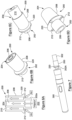
- the embodiment shown in Figures 6A to 6D is a mouthpiece 200 for attachment to a conventional pulmonary delivery device, such as the device 300 shown in Figure 7 .
- the mouthpiece has a first inlet end 202 and a second outlet end 204 with a first central chamber 206 consisting of a cylindrical tube which is adapted for receipt within a main body of a pulmonary delivery device 300 at the inlet end 202 of the mouthpiece.
- a second chamber 208 concentrically surrounds the first chamber, the second chamber being adapted for receipt of at least one flavour or aroma 210 and having at least one air inlet 212 at the inlet end.
- the first chamber 206 of the mouthpiece extends beyond the inlet end of the second chamber.
- the outlet ends 204 of the chambers are substantially co-terminus.
- the inlet end of the second chamber is provided with an annular flange 220 extending perpendicularly from the second chamber, the flange having the at least one air inlet 212 in fluid communication with the second chamber.
- a portion 202a of the first chamber extends beyond the flange for receipt within a main body of a pulmonary delivery device and the flange is adapted to rest or engage with the sides of the main body, whereby the air inlets of the second chamber are positioned beyond the sides of the main body.
- a filter tip 302 may also be received at the outlet end 204 of the mouthpiece (see Figure 7 ).
- multiple air inlets 212 may be provided at the inlet end of the second chamber, preferably being spaced equidistant apart around the perimeter of the second chamber to optimize air flow into the second chamber. Ideally, the air inlets 212 lie adjacent the portion of the first chamber that extends beyond the flange.
- flavour block 210 may be provided within the second chamber 208.
- warm wet vapour from the main body of the device enters the first chamber 206 of the mouthpiece.
- air is able to enter the second chamber through air inlets 212 to atomise the flavour in the flavour block.
- flavouring such as an oil
- This arrangement is not only less detrimental to health because the flavouring, such as an oil, is not subjected to heat, but also enables the mouthpiece to be easily changed for a mouthpiece having a different flavor block, without any contamination of the main pulmonary delivery device.
- the nicotine or other active agent is also delivered via the cold chamber.
- a heated aerosol typically flavourless
- the nicotine or other active agent is thought to increase customer satisfaction and is likely to result in a product more akin to customer expectations of a nicotine-containing product.
- the embodiment shown in Figures 6A to 6D and 7 is preferably formed from a simple two piece construction.
- the mouthpiece may be disposed of after use and replaced with a new mouthpiece or may have the flavor block removed, be cleaned and a new flavor block inserted.
- this provides an easy mechanism for a user to change the flavor or their device, for example from cherry to menthol.
- FIG. 8A to 8A Another embodiment of a mouthpiece according to the present disclosure is shown in Figures 8A to 8A .
- the mouthpiece 400 is similar to mouthpiece shown in Figures 6A to 6D but the annular flange 420 is formed as part of the moulding forming the first mouthpiece chamber 406 and a cylindrical sleeve 408a rests on the flange to form the second chamber 408.
- Air inlets 412 are provided through the flange and the portion of the first mouthpiece that extends beyond the inlet end 402 of the second chamber is threaded for engagement with the heated chamber of a pulmonary delivery device (not shown).
- the sleeve is preferably of a more malleable material than the rest of the mouthpiece to increase user comfort.
- the number of air inlets that are open to the second chamber are selectively adjustable to vary the flow of air through this chamber. This enables a user to select the amount of flavour that is inhaled and mixed with the hot vapour. Alternatively, or additionally, more than one type of flavour may be provided in the second chamber with the user being able to select which air inlets to open dependent upon which flavour is to be inhaled.
- the mouthpiece may have means for opening and closing the air inlets to the second chamber thereby enabling the volume of air entering the second chamber to be adjusted (not shown).
- the second chamber may be at least partially rotatable with respect to the first chamber to open and close the air inlets or vice versa.
- the walls of the cylinder forming the second chamber may be provided with spaced apart protruberances or tabs that can extend over and close the air inlets depending upon the degree of rotation of the second cylinder with respect of the first chamber.
- the second chamber is provided with multiple flavour blocks and the air inlets may be opened to allow flavour from only the desired flavour of the block.
- the flavour block may comprise two half sections, each being of a different flavour, and the mouthpiece is provided with means for opening only the air inlets adjacent one of the half sections, such as by the provision of a rotatable or slidable shutter.
- the flavours may be provided in inner and outer concentric rings within the second chamber having air inlets provided in a corresponding arrangement of inner and outer concentric rings, wherein the mouthpiece is provided with means for selective opening and closing of the air inlets of inner or outer concentric rings. This would enable a user to easily select a particular flavour without having to change the mouthpiece. This is desirable as many users get used to a flavour very quickly and may wish to alternate flavours, such as cherry and mint, throughout the day.
Landscapes
- Health & Medical Sciences (AREA)
- Engineering & Computer Science (AREA)
- Anesthesiology (AREA)
- Biomedical Technology (AREA)
- Heart & Thoracic Surgery (AREA)
- Hematology (AREA)
- Life Sciences & Earth Sciences (AREA)
- Animal Behavior & Ethology (AREA)
- General Health & Medical Sciences (AREA)
- Public Health (AREA)
- Veterinary Medicine (AREA)
- Bioinformatics & Cheminformatics (AREA)
- Pulmonology (AREA)
- Medicinal Preparation (AREA)
Claims (15)
- Vorrichtung zur pulmonalen Abgabe (300), die Folgendes umfasst: eine erste Kammer, die zum thermischen Verdampfen einer Menge einer ersten Flüssigkeit geeignet ist, um einen ersten Dampf zu bilden, und eine zweite Kammer, die zum Zerstäuben einer Menge einer zweiten Flüssigkeit ohne Erhitzen der zweiten Flüssigkeit geeignet ist, um einen Nebel eines zweiten Dampfes zu bilden, wobei die Vorrichtung weiter einen Auslass umfasst, über den bei Verwendung ein Anwender eine Mischung des ersten und zweiten Dampfes inhalieren kann, dadurch gekennzeichnet, dass die Vorrichtung ein Mundstück (200) enthält, das mit dem Auslass der ersten Kammer verbindbar ist, um eine Verlängerung (206) an der ersten Kammer bereitzustellen, wobei das Mundstück die zweite Kammer (208) in der Form eines passiven Zerstäubers bereitstellt, wobei die zweite Kammer mindestens einen Lufteinlass (212) aufweist und selektiv oder kontinuierlich mit Luft in fließender Verbindung ist, wobei die zweite Kammer 208) mindestens einen Aromastoff oder ein Aroma (210) und optional ein aktives Molekül oder Medikament einschließt, wobei der Aromastoff und optional das andere aktive Molekül oder Medikament durch Ziehen von Luft durch die zweite Kammer (208) inhaliert werden.
- Vorrichtung zur pulmonalen Abgabe nach Anspruch 1, wobei die erste Kammer mit einer Heizquelle zur Verdampfung der ersten Flüssigkeit bereitgestellt ist oder damit verbunden ist, bevorzugt wobei die erste Flüssigkeit eine Trägerflüssigkeit (d. h. eine Flüssigkeit, die einen stabilen Dampf bilden kann) ist, die aus Wasser und einer Wasser-Glykol-Mischung ausgewählt ist.
- Vorrichtung zur pulmonalen Abgabe nach Anspruch 1 oder 2, wobei der Aromastoff in einer festen oder halbfesten Form innerhalb der zweiten Kammer (208) bereitgestellt ist.
- Vorrichtung zur pulmonalen Abgabe nach einem der Ansprüche 1 bis 3, wobei das Volumen von Flüssigkeit, die durch die zweite Kammer (208) hindurchgeht, selektiv einstellbar ist und der Zerstäuber zur Bereitstellung einer Partikelgröße mit einem durchschnittlichen Durchmesser von 5-50 µm konfiguriert ist.
- Vorrichtung zur pulmonalen Abgabe nach einem der vorstehenden Ansprüche, wobei das Mundstück (200) reversibel abnehmbar ist.
- Vorrichtung zur pulmonalen Abgabe nach Anspruch 5, wobei die zweite Kammer (208) die Verlängerung (206) an der ersten Kammer umgibt.
- Vorrichtung zur pulmonalen Abgabe nach Anspruch 6, wobei das Mundstück eine mittlere erste Kammer und eine konzentrische äußere zweite Kammer umfasst, optional wobei die mittlere erste Kammer (206) des Mundstücks zur Aufnahme innerhalb einer ersten Hauptkammer dimensioniert ist, die in der Vorrichtung zur pulmonalen Abgabe (300) bereitgestellt ist, die den erhitzten oder warmen Dampf erzeugt, bevorzugt wobei die äußere zweite Kammer (208) in einem Flansch (220) endet, der den mindestens einen Lufteinlass (212) aufweist, wobei der Flansch auf einer oberen Oberfläche der ersten Hauptkammer des Hauptkörpers der Vorrichtung zur pulmonalen Abgabe aufgenommen ist.
- Vorrichtung zur pulmonalen Abgabe nach einem der Ansprüche 5 bis 7, wobei sich ein ringförmiger Flansch (220) lateral von der ersten Kammer des Mundstücks erstreckt, wobei der Flansch den mindestens einen Lufteinlass in die zweite Kammer, die die erste Kammer umgibt, aufweist, bevorzugt wobei mehrere Lufteinlässe in die zweite Kammer bereitgestellt sind und der Eintritt von Luft durch die Lufteinlässe durch Einstellung der Anzahl und/oder Größe der Lufteinlässe, die in die zweite Kammer geöffnet sind, einstellbar ist.
- Vorrichtung zur pulmonalen Abgabe nach Anspruch 8, wobei das Mundstück zwei Teile umfasst, wobei ein Teil die mittlere erste Kammer (206) des Mundstücks bildet, wobei mindestens ein Bereich der ersten Kammer Lufteinlässe in fließender Verbindung mit einer zweiten Kammer (208) einschließt, die durch einen zweiten Teil gebildet ist, der den ersten Teil umgibt, und wobei der erste Teil und zweite Teil zumindest teilweise in Bezug aufeinander drehbar sind, um das Schließen oder Öffnen von einem oder mehreren Lufteinlässen (212), die in dem ersten Teil bereitgestellt sind, zu bewirken.
- Vorrichtung zur pulmonalen Abgabe nach einem der Ansprüche 5 bis 9, wobei das Mundstück Mittel zum gleichzeitigen selektiven Schließen eines Bereichs der Lufteinlässe (212) einschließt, bevorzugt wobei ein halber Abschnitt der Lufteinlässe geöffnet sein kann, während der gegenüberliegende halbe Abschnitt geschlossen ist, bevorzugt wobei zwei halbzylindrische Aromastoffblöcke in gegenüberliegenden Seiten der zweiten Mundstückkammer bereitgestellt sind, wobei eine Hälfte der Lufteinlässe gleichzeitig auf der Seite der Kammer, die den gewünschten Aromastoff enthält, temporär geöffnet sein kann.
- Mundstück (200) für eine Vorrichtung zur pulmonalen Abgabe, wobei das Mundstück ein erstes Einlassende (202) und ein zweites Auslassende (204) aufweist und Folgendes umfasst: eine erste Kammer (206), die zur Aufnahme innerhalb eines Hauptkörpers einer Vorrichtung zur pulmonalen Abgabe an dem Einlassende des Mundstücks geeignet ist, und eine zweite Kammer (208), wobei die zweite Kammer zur Aufnahme von mindestens einem Aromastoff oder Aroma (210), bevorzugt in der Form eines festen oder halbfesten Blocks, geeignet ist und mindestens einen Lufteinlass (212) an dem Einlassende aufweist, wobei die zweite Kammer selektiv oder kontinuierlich mit Luft in fließender Verbindung ist, wobei sich die erste Kammer des Mundstücks über das Ende der zweiten Kammer hinaus an dem Einlassende des Mundstücks erstreckt und die Kammern im Wesentlichen an dem Auslassende des Mundstücks gemeinsam enden.
- Mundstück nach Anspruch 11, wobei die zweite Kammer (208) zumindest teilweise die erste Kammer (206) des Mundstücks (200) umgibt.
- Mundstück nach Anspruch 11 oder Anspruch 12, wobei das Einlassende der zweiten Kammer (208) mit einem ringförmigen Flansch (220) bereitgestellt ist, der sich im Wesentlichen senkrecht von der zweiten Kammer erstreckt, wobei der Flansch mindestens einen Lufteinlass (212) in fließender Verbindung mit der zweiten Kammer aufweist, bevorzugt wobei sich ein Bereich der ersten Kammer (206) über den Flansch hinaus zur Aufnahme innerhalb eines Hauptkörpers einer Vorrichtung zur pulmonalen Abgabe erstreckt und der Flansch zum Aufliegen oder Eingreifen in die Seiten des Hautkörpers geeignet ist, wobei die Lufteinlässe der zweiten Kammer über die Seiten des Hauptkörpers hinaus positioniert sind, insbesondere wobei das Einlassende der ersten Kammer mit einem ringförmigen Flansch bereitgestellt ist, wobei der Flansch mit einer Reihe von Löchern zur Bildung von Lufteinlässen in die zweite Kammer, die die erste Kammer umgibt, bereitgestellt ist.
- Mundstück nach einem der Ansprüche 11 bis 13, wobei mehrere Lufteinlässe (212) an dem Einlassende der zweiten Kammer (208) bereitgestellt sind, die bevorzugt äquidistant um den Umfang der zweiten Kammer beabstandet sind, wobei das Mundstück Mittel zum selektiven Öffnen und Schließen der Lufteinlässe zu der zweiten Kammer einschließt.
- Mundstück nach Anspruch 14, wobei die zweite Kammer (208) durch eine zylindrische Wand gebildet ist, die zumindest teilweise in Bezug auf die erste Kammer drehbar ist, um die Lufteinlässe (212) selektiv zu öffnen und zu schließen, die bevorzugt mit einer Reihe von Vorsprüngen zur selektiven Abdeckung der Lufteinlässe in Abhängigkeit vom Grad der Drehung der zweiten Kammer bereitgestellt sind, und optional wobei der Aromastoff zwei halbe Abschnitte umfasst, wobei jeder Abschnitt ein anderer Aromastoff ist, und das Mundstück mit Mitteln zum Öffnen von nur den Lufteinlässen bereitgestellt ist, die benachbart zu einem der halben Abschnitte vorliegen.
Applications Claiming Priority (3)
| Application Number | Priority Date | Filing Date | Title |
|---|---|---|---|
| GBGB1712749.9A GB201712749D0 (en) | 2017-08-09 | 2017-08-09 | Pulmonary delivery devices |
| GBGB1714880.0A GB201714880D0 (en) | 2017-09-15 | 2017-09-15 | Pulmonary delivery devices |
| PCT/IB2018/055626 WO2019030602A1 (en) | 2017-08-09 | 2018-07-27 | PULMONARY DELIVERY DEVICES |
Publications (2)
| Publication Number | Publication Date |
|---|---|
| EP3664876A1 EP3664876A1 (de) | 2020-06-17 |
| EP3664876B1 true EP3664876B1 (de) | 2025-06-18 |
Family
ID=63452686
Family Applications (1)
| Application Number | Title | Priority Date | Filing Date |
|---|---|---|---|
| EP18762921.7A Active EP3664876B1 (de) | 2017-08-09 | 2018-07-27 | Pulmonale freisetzungsvorrichtungen |
Country Status (8)
| Country | Link |
|---|---|
| US (3) | US11504486B2 (de) |
| EP (1) | EP3664876B1 (de) |
| JP (2) | JP7171723B2 (de) |
| CN (2) | CN111163820B (de) |
| GB (1) | GB2566802B (de) |
| PL (1) | PL3664876T3 (de) |
| RU (1) | RU2766733C2 (de) |
| WO (1) | WO2019030602A1 (de) |
Families Citing this family (20)
| Publication number | Priority date | Publication date | Assignee | Title |
|---|---|---|---|---|
| WO2019030602A1 (en) * | 2017-08-09 | 2019-02-14 | Twenty Sixteen (2016) Pharma Limited | PULMONARY DELIVERY DEVICES |
| US10786010B2 (en) | 2017-12-15 | 2020-09-29 | Rai Strategic Holdings, Inc. | Aerosol delivery device with multiple aerosol delivery pathways |
| WO2020097052A1 (en) * | 2018-11-05 | 2020-05-14 | Juul Labs, Inc. | Cartridges for vaporizer devices |
| US11607506B2 (en) | 2019-02-22 | 2023-03-21 | Altria Client Services Llc | Electronic dispersion device |
| US12564218B2 (en) * | 2019-08-29 | 2026-03-03 | Rai Strategic Holdings, Inc. | Dual-chamber aerosol dispenser |
| US11684083B2 (en) | 2019-12-09 | 2023-06-27 | Scott Reimann | Hexagonal cartridge having a hexagon shaped mouthpiece with six air flow inlets |
| US11109622B1 (en) * | 2020-03-30 | 2021-09-07 | Gofire, Inc. | System and method for metered dosing vaporizer |
| EP3888477B1 (de) * | 2020-03-30 | 2025-08-06 | Imperial Tobacco Limited | Aerosolabgabekomponente |
| WO2021262799A1 (en) | 2020-06-23 | 2021-12-30 | Flagship Pioneering, Inc. | Anti-viral compounds and methods of using same |
| CN114431541B (zh) * | 2020-11-04 | 2025-09-05 | 深圳市合元科技有限公司 | 气溶胶生成装置及其控制方法 |
| EP4294219B1 (de) * | 2021-02-18 | 2025-04-02 | Philip Morris Products S.A. | Austauschbare kartusche für eine aerosolerzeugungsvorrichtung mit verschiebbarem dichtungselement |
| KR102531112B1 (ko) * | 2021-03-11 | 2023-05-10 | 주식회사 케이티앤지 | 흐름 통로를 포함하는 에어로졸 생성 장치 |
| CN113289172B (zh) * | 2021-05-31 | 2023-11-03 | 成都中医药大学附属医院 | 用于治疗急诊创伤性疼痛的芳香化甲氧氟烷吸入装置 |
| EP4098134A1 (de) * | 2021-05-31 | 2022-12-07 | JT International S.A. | Aerosolerzeugendes verbrauchsmaterial mit einem aromatisierungsteil und zugehöriger aerosolerzeugungssatz |
| US12090265B2 (en) * | 2021-09-20 | 2024-09-17 | Cartean (Henan) Technology Co., Ltd. | Ultrasonic electronic rhinitis therapeutic apparatus with far-infrared atomized coconut essential oil |
| US12402660B2 (en) | 2022-03-22 | 2025-09-02 | Curb Living, Inc. | Handheld vaping implement |
| GB202219330D0 (en) | 2022-12-21 | 2023-02-01 | Twenty Sixteen 2016 Pharma Ltd | Pulmonary delivery devices |
| PL243803B1 (pl) * | 2023-01-16 | 2023-10-16 | Lubelska Polt | Układ do dozowania substancji zapachowych do wdychanego powietrza |
| US20240277947A1 (en) * | 2023-02-17 | 2024-08-22 | Kind Distribution LLC | Adapter for vaporization attachments |
| US11871793B1 (en) * | 2023-07-06 | 2024-01-16 | Benyamin Abehasera | Smart electronic smoking device |
Citations (1)
| Publication number | Priority date | Publication date | Assignee | Title |
|---|---|---|---|---|
| US3949743A (en) * | 1973-03-19 | 1976-04-13 | Schick Incorporated | Medicated vapor production method and apparatus |
Family Cites Families (37)
| Publication number | Priority date | Publication date | Assignee | Title |
|---|---|---|---|---|
| JPH01117355U (de) * | 1988-01-28 | 1989-08-08 | ||
| JP2984657B2 (ja) * | 1997-07-23 | 1999-11-29 | 日本たばこ産業株式会社 | 香味発生装置 |
| JP3327826B2 (ja) * | 1997-12-05 | 2002-09-24 | 日本たばこ産業株式会社 | 香味生成物品及び香味生成器具 |
| GB0112888D0 (en) * | 2001-05-26 | 2001-07-18 | Innovata Biomed Ltd | Device |
| JP2004159675A (ja) * | 2002-11-08 | 2004-06-10 | Yoshihiro Kizu | 香料吸引パイプ |
| US7913686B2 (en) * | 2002-12-19 | 2011-03-29 | Scadds Incorporated | Self contained aerosol dual delivery system (SCADDS) |
| JP5118701B2 (ja) * | 2006-08-22 | 2013-01-16 | グラクソ グループ リミテッド | 薬剤ディスペンサー |
| US7726320B2 (en) * | 2006-10-18 | 2010-06-01 | R. J. Reynolds Tobacco Company | Tobacco-containing smoking article |
| AT508244B1 (de) | 2010-03-10 | 2010-12-15 | Helmut Dr Buchberger | Inhalatorkomponente |
| US9861772B2 (en) * | 2010-05-15 | 2018-01-09 | Rai Strategic Holdings, Inc. | Personal vaporizing inhaler cartridge |
| MY156633A (en) * | 2010-08-20 | 2016-03-15 | Japan Tobacco Inc | Tobacco-flavor-releasing material and non-heating type tobacco flavor inhalator containing same |
| EP3508083B1 (de) * | 2010-08-24 | 2021-07-14 | JT International S.A. | Inhalationsvorrichtung mit substanzverwendungssteuerung |
| SG11201504008PA (en) * | 2012-11-28 | 2015-06-29 | Nicotine Technology Inc E | Methods and devices for compound delivery |
| US10034988B2 (en) | 2012-11-28 | 2018-07-31 | Fontem Holdings I B.V. | Methods and devices for compound delivery |
| KR102278193B1 (ko) * | 2013-05-21 | 2021-07-19 | 필립모리스 프로덕츠 에스.에이. | 전기 가열식 에어로졸 전달 시스템 |
| GB2522727B (en) * | 2013-11-26 | 2017-01-25 | Purity Health Pharma Ltd | Pulmonary delivery devices |
| GB201320834D0 (en) * | 2013-11-26 | 2014-01-08 | Guise Andrew | Pulmonary delivery devices |
| CN103783673A (zh) * | 2014-01-23 | 2014-05-14 | 深圳市合元科技有限公司 | 雾化器及其烟雾吸入装置 |
| TWI660685B (zh) | 2014-05-21 | 2019-06-01 | 瑞士商菲利浦莫里斯製品股份有限公司 | 電熱式氣溶膠產生系統及用於此系統中之匣筒 |
| GB201412954D0 (en) | 2014-07-22 | 2014-09-03 | Nicoventures Holdings Ltd | Electronic vapour provision system |
| GB2529201A (en) * | 2014-08-13 | 2016-02-17 | Batmark Ltd | Device and method |
| CN107106797A (zh) * | 2014-10-29 | 2017-08-29 | 奥驰亚客户服务有限责任公司 | 电子烟筒体 |
| HK1243893A1 (zh) * | 2015-02-27 | 2018-07-27 | British American Tobacco (Investments) Limited | 用於生成可吸入介质的料筒、部件以及方法 |
| JP7189765B2 (ja) * | 2015-04-15 | 2022-12-14 | フィリップ・モーリス・プロダクツ・ソシエテ・アノニム | 吸入装置のための香味要素 |
| JP6827424B2 (ja) * | 2015-05-06 | 2021-02-10 | アルトリア クライアント サービシーズ エルエルシー | 非燃焼型喫煙デバイスおよびそのエレメント |
| US9888723B2 (en) | 2015-05-15 | 2018-02-13 | Lunatech, Llc | Hybrid vapor delivery system utilizing nebulized and non-nebulized elements |
| GB201520056D0 (en) * | 2015-11-13 | 2015-12-30 | British American Tobacco Co | Tobacco blend |
| US12501928B2 (en) | 2016-03-11 | 2025-12-23 | Altria Client Services Llc | Multiple dispersion generating e-vaping device having a dual piston cylinder, configured to reduce a transmission of a pressure force from a carbon dioxide capsule to a tank configured to store a pre-aerosol formulation |
| CN118319066A (zh) | 2016-04-22 | 2024-07-12 | 尤尔实验室有限公司 | 具有间隔材料的气雾剂装置 |
| GB201615608D0 (en) * | 2016-09-14 | 2016-10-26 | British American Tobacco Investments Ltd | A container |
| WO2018086999A1 (en) * | 2016-11-14 | 2018-05-17 | Philip Morris Products S.A. | Aerosol-generating system having variable airflow |
| CN206542922U (zh) * | 2017-03-14 | 2017-10-10 | 常州市派腾电子技术服务有限公司 | 雾化头、雾化器及电子烟 |
| CN108851229A (zh) * | 2017-05-15 | 2018-11-23 | 深圳市康尔科技有限公司 | 多个加热元件的雾化器以及具有多个加热元件雾化器的电子烟 |
| WO2019012151A1 (en) | 2017-07-14 | 2019-01-17 | Philip Morris Products S.A. | AEROSOL GENERATION SYSTEM WITH VENTILATION AIR FLOW |
| WO2019030602A1 (en) * | 2017-08-09 | 2019-02-14 | Twenty Sixteen (2016) Pharma Limited | PULMONARY DELIVERY DEVICES |
| US10786010B2 (en) * | 2017-12-15 | 2020-09-29 | Rai Strategic Holdings, Inc. | Aerosol delivery device with multiple aerosol delivery pathways |
| CA3098251A1 (en) | 2018-04-24 | 2019-10-31 | Jt International Sa | Electronic cigarette with optimised vaporisation |
-
2018
- 2018-07-27 WO PCT/IB2018/055626 patent/WO2019030602A1/en not_active Ceased
- 2018-07-27 CN CN201880064455.6A patent/CN111163820B/zh active Active
- 2018-07-27 EP EP18762921.7A patent/EP3664876B1/de active Active
- 2018-07-27 RU RU2020109467A patent/RU2766733C2/ru active
- 2018-07-27 GB GB1812265.5A patent/GB2566802B/en active Active
- 2018-07-27 US US16/636,423 patent/US11504486B2/en active Active
- 2018-07-27 CN CN202310087569.5A patent/CN115813044B/zh active Active
- 2018-07-27 PL PL18762921.7T patent/PL3664876T3/pl unknown
- 2018-07-27 JP JP2020529836A patent/JP7171723B2/ja active Active
-
2022
- 2022-11-02 JP JP2022175928A patent/JP7487273B2/ja active Active
- 2022-11-04 US US17/980,621 patent/US20230057288A1/en not_active Abandoned
-
2023
- 2023-12-06 US US18/530,429 patent/US12453825B2/en active Active
Patent Citations (1)
| Publication number | Priority date | Publication date | Assignee | Title |
|---|---|---|---|---|
| US3949743A (en) * | 1973-03-19 | 1976-04-13 | Schick Incorporated | Medicated vapor production method and apparatus |
Also Published As
| Publication number | Publication date |
|---|---|
| PL3664876T3 (pl) | 2025-11-03 |
| CN111163820A (zh) | 2020-05-15 |
| US12453825B2 (en) | 2025-10-28 |
| GB2566802B (en) | 2022-06-22 |
| GB201812265D0 (en) | 2018-09-12 |
| US20200170301A1 (en) | 2020-06-04 |
| RU2020109467A3 (de) | 2021-09-10 |
| JP2020529911A (ja) | 2020-10-15 |
| US20230057288A1 (en) | 2023-02-23 |
| CN115813044A (zh) | 2023-03-21 |
| JP7487273B2 (ja) | 2024-05-20 |
| RU2766733C2 (ru) | 2022-03-15 |
| JP2023017886A (ja) | 2023-02-07 |
| GB2566802A (en) | 2019-03-27 |
| EP3664876A1 (de) | 2020-06-17 |
| WO2019030602A1 (en) | 2019-02-14 |
| RU2020109467A (ru) | 2021-09-10 |
| JP7171723B2 (ja) | 2022-11-15 |
| CN111163820B (zh) | 2023-02-21 |
| CN115813044B (zh) | 2025-10-28 |
| US20240100265A1 (en) | 2024-03-28 |
| US11504486B2 (en) | 2022-11-22 |
Similar Documents
| Publication | Publication Date | Title |
|---|---|---|
| US12453825B2 (en) | Mouthpiece of pulmonary delivery device having warm and cold chambers | |
| US20230405243A1 (en) | Pulmonary delivery devices | |
| EP3102056B1 (de) | Vorrichtungen zur pulmonalen verabreichung | |
| GB2524856A (en) | Pulmonary delivery devices | |
| JP7753553B2 (ja) | エアロゾル供給システム | |
| EP3349605A2 (de) | Inhalierbare zusammensetzung und inhalator | |
| NZ582152A (en) | An inhalable composition comprising nicotine and oxygen | |
| US12064547B2 (en) | Dry powder inhaler device | |
| AU2016247916A1 (en) | Flavoring element for an inhalation device | |
| CN112165967B (zh) | 喷雾装置、喷雾单元和喷雾套筒 | |
| US20040065324A1 (en) | Thermal inhaler | |
| WO2024133260A1 (en) | Pulmonary delivery devices | |
| CN112274737B (zh) | 一种医用鼻吸设备 |
Legal Events
| Date | Code | Title | Description |
|---|---|---|---|
| STAA | Information on the status of an ep patent application or granted ep patent |
Free format text: STATUS: UNKNOWN |
|
| STAA | Information on the status of an ep patent application or granted ep patent |
Free format text: STATUS: THE INTERNATIONAL PUBLICATION HAS BEEN MADE |
|
| PUAI | Public reference made under article 153(3) epc to a published international application that has entered the european phase |
Free format text: ORIGINAL CODE: 0009012 |
|
| STAA | Information on the status of an ep patent application or granted ep patent |
Free format text: STATUS: REQUEST FOR EXAMINATION WAS MADE |
|
| 17P | Request for examination filed |
Effective date: 20200224 |
|
| AK | Designated contracting states |
Kind code of ref document: A1 Designated state(s): AL AT BE BG CH CY CZ DE DK EE ES FI FR GB GR HR HU IE IS IT LI LT LU LV MC MK MT NL NO PL PT RO RS SE SI SK SM TR |
|
| AX | Request for extension of the european patent |
Extension state: BA ME |
|
| DAV | Request for validation of the european patent (deleted) | ||
| DAX | Request for extension of the european patent (deleted) | ||
| STAA | Information on the status of an ep patent application or granted ep patent |
Free format text: STATUS: EXAMINATION IS IN PROGRESS |
|
| 17Q | First examination report despatched |
Effective date: 20221206 |
|
| REG | Reference to a national code |
Ref country code: DE Ref legal event code: R079 Free format text: PREVIOUS MAIN CLASS: A61M0011000000 Ipc: A24F0040300000 Ref country code: DE Ref legal event code: R079 Ref document number: 602018082674 Country of ref document: DE Free format text: PREVIOUS MAIN CLASS: A61M0011000000 Ipc: A24F0040300000 |
|
| RIC1 | Information provided on ipc code assigned before grant |
Ipc: A61M 11/04 20060101ALI20231121BHEP Ipc: A61M 11/02 20060101ALI20231121BHEP Ipc: A61M 11/00 20060101ALI20231121BHEP Ipc: A24F 40/485 20200101ALI20231121BHEP Ipc: A24F 40/30 20200101AFI20231121BHEP |
|
| GRAP | Despatch of communication of intention to grant a patent |
Free format text: ORIGINAL CODE: EPIDOSNIGR1 |
|
| STAA | Information on the status of an ep patent application or granted ep patent |
Free format text: STATUS: GRANT OF PATENT IS INTENDED |
|
| INTG | Intention to grant announced |
Effective date: 20250124 |
|
| GRAS | Grant fee paid |
Free format text: ORIGINAL CODE: EPIDOSNIGR3 |
|
| GRAA | (expected) grant |
Free format text: ORIGINAL CODE: 0009210 |
|
| STAA | Information on the status of an ep patent application or granted ep patent |
Free format text: STATUS: THE PATENT HAS BEEN GRANTED |
|
| AK | Designated contracting states |
Kind code of ref document: B1 Designated state(s): AL AT BE BG CH CY CZ DE DK EE ES FI FR GB GR HR HU IE IS IT LI LT LU LV MC MK MT NL NO PL PT RO RS SE SI SK SM TR |
|
| REG | Reference to a national code |
Ref country code: GB Ref legal event code: FG4D |
|
| REG | Reference to a national code |
Ref country code: CH Ref legal event code: EP |
|
| REG | Reference to a national code |
Ref country code: DE Ref legal event code: R096 Ref document number: 602018082674 Country of ref document: DE |
|
| REG | Reference to a national code |
Ref country code: CH Ref legal event code: EP |
|
| REG | Reference to a national code |
Ref country code: IE Ref legal event code: FG4D |
|
| PG25 | Lapsed in a contracting state [announced via postgrant information from national office to epo] |
Ref country code: FI Free format text: LAPSE BECAUSE OF FAILURE TO SUBMIT A TRANSLATION OF THE DESCRIPTION OR TO PAY THE FEE WITHIN THE PRESCRIBED TIME-LIMIT Effective date: 20250618 |
|
| PGFP | Annual fee paid to national office [announced via postgrant information from national office to epo] |
Ref country code: DE Payment date: 20250828 Year of fee payment: 8 |
|
| REG | Reference to a national code |
Ref country code: LT Ref legal event code: MG9D |
|
| PG25 | Lapsed in a contracting state [announced via postgrant information from national office to epo] |
Ref country code: GR Free format text: LAPSE BECAUSE OF FAILURE TO SUBMIT A TRANSLATION OF THE DESCRIPTION OR TO PAY THE FEE WITHIN THE PRESCRIBED TIME-LIMIT Effective date: 20250919 Ref country code: NO Free format text: LAPSE BECAUSE OF FAILURE TO SUBMIT A TRANSLATION OF THE DESCRIPTION OR TO PAY THE FEE WITHIN THE PRESCRIBED TIME-LIMIT Effective date: 20250918 |
|
| PG25 | Lapsed in a contracting state [announced via postgrant information from national office to epo] |
Ref country code: BG Free format text: LAPSE BECAUSE OF FAILURE TO SUBMIT A TRANSLATION OF THE DESCRIPTION OR TO PAY THE FEE WITHIN THE PRESCRIBED TIME-LIMIT Effective date: 20250618 |
|
| PGFP | Annual fee paid to national office [announced via postgrant information from national office to epo] |
Ref country code: GB Payment date: 20250828 Year of fee payment: 8 |
|
| PG25 | Lapsed in a contracting state [announced via postgrant information from national office to epo] |
Ref country code: HR Free format text: LAPSE BECAUSE OF FAILURE TO SUBMIT A TRANSLATION OF THE DESCRIPTION OR TO PAY THE FEE WITHIN THE PRESCRIBED TIME-LIMIT Effective date: 20250618 |
|
| PGFP | Annual fee paid to national office [announced via postgrant information from national office to epo] |
Ref country code: FR Payment date: 20250826 Year of fee payment: 8 |
|
| PG25 | Lapsed in a contracting state [announced via postgrant information from national office to epo] |
Ref country code: RS Free format text: LAPSE BECAUSE OF FAILURE TO SUBMIT A TRANSLATION OF THE DESCRIPTION OR TO PAY THE FEE WITHIN THE PRESCRIBED TIME-LIMIT Effective date: 20250918 |
|
| REG | Reference to a national code |
Ref country code: NL Ref legal event code: MP Effective date: 20250618 |
|
| PG25 | Lapsed in a contracting state [announced via postgrant information from national office to epo] |
Ref country code: LV Free format text: LAPSE BECAUSE OF FAILURE TO SUBMIT A TRANSLATION OF THE DESCRIPTION OR TO PAY THE FEE WITHIN THE PRESCRIBED TIME-LIMIT Effective date: 20250618 |
|
| PG25 | Lapsed in a contracting state [announced via postgrant information from national office to epo] |
Ref country code: NL Free format text: LAPSE BECAUSE OF FAILURE TO SUBMIT A TRANSLATION OF THE DESCRIPTION OR TO PAY THE FEE WITHIN THE PRESCRIBED TIME-LIMIT Effective date: 20250618 |
|
| PG25 | Lapsed in a contracting state [announced via postgrant information from national office to epo] |
Ref country code: PT Free format text: LAPSE BECAUSE OF FAILURE TO SUBMIT A TRANSLATION OF THE DESCRIPTION OR TO PAY THE FEE WITHIN THE PRESCRIBED TIME-LIMIT Effective date: 20251020 |
|
| REG | Reference to a national code |
Ref country code: AT Ref legal event code: MK05 Ref document number: 1803365 Country of ref document: AT Kind code of ref document: T Effective date: 20250618 |
|
| PG25 | Lapsed in a contracting state [announced via postgrant information from national office to epo] |
Ref country code: IS Free format text: LAPSE BECAUSE OF FAILURE TO SUBMIT A TRANSLATION OF THE DESCRIPTION OR TO PAY THE FEE WITHIN THE PRESCRIBED TIME-LIMIT Effective date: 20251018 |
|
| PG25 | Lapsed in a contracting state [announced via postgrant information from national office to epo] |
Ref country code: AT Free format text: LAPSE BECAUSE OF FAILURE TO SUBMIT A TRANSLATION OF THE DESCRIPTION OR TO PAY THE FEE WITHIN THE PRESCRIBED TIME-LIMIT Effective date: 20250618 Ref country code: SM Free format text: LAPSE BECAUSE OF FAILURE TO SUBMIT A TRANSLATION OF THE DESCRIPTION OR TO PAY THE FEE WITHIN THE PRESCRIBED TIME-LIMIT Effective date: 20250618 |
|
| PG25 | Lapsed in a contracting state [announced via postgrant information from national office to epo] |
Ref country code: CZ Free format text: LAPSE BECAUSE OF FAILURE TO SUBMIT A TRANSLATION OF THE DESCRIPTION OR TO PAY THE FEE WITHIN THE PRESCRIBED TIME-LIMIT Effective date: 20250618 |
|
| PGFP | Annual fee paid to national office [announced via postgrant information from national office to epo] |
Ref country code: PL Payment date: 20250827 Year of fee payment: 8 |
|
| PG25 | Lapsed in a contracting state [announced via postgrant information from national office to epo] |
Ref country code: EE Free format text: LAPSE BECAUSE OF FAILURE TO SUBMIT A TRANSLATION OF THE DESCRIPTION OR TO PAY THE FEE WITHIN THE PRESCRIBED TIME-LIMIT Effective date: 20250618 |
|
| PG25 | Lapsed in a contracting state [announced via postgrant information from national office to epo] |
Ref country code: SK Free format text: LAPSE BECAUSE OF FAILURE TO SUBMIT A TRANSLATION OF THE DESCRIPTION OR TO PAY THE FEE WITHIN THE PRESCRIBED TIME-LIMIT Effective date: 20250618 Ref country code: RO Free format text: LAPSE BECAUSE OF FAILURE TO SUBMIT A TRANSLATION OF THE DESCRIPTION OR TO PAY THE FEE WITHIN THE PRESCRIBED TIME-LIMIT Effective date: 20250618 |
|
| PG25 | Lapsed in a contracting state [announced via postgrant information from national office to epo] |
Ref country code: ES Free format text: LAPSE BECAUSE OF FAILURE TO SUBMIT A TRANSLATION OF THE DESCRIPTION OR TO PAY THE FEE WITHIN THE PRESCRIBED TIME-LIMIT Effective date: 20250618 |
|
| REG | Reference to a national code |
Ref country code: CH Ref legal event code: H13 Free format text: ST27 STATUS EVENT CODE: U-0-0-H10-H13 (AS PROVIDED BY THE NATIONAL OFFICE) Effective date: 20260224 |
|
| PG25 | Lapsed in a contracting state [announced via postgrant information from national office to epo] |
Ref country code: LU Free format text: LAPSE BECAUSE OF NON-PAYMENT OF DUE FEES Effective date: 20250727 |
|
| REG | Reference to a national code |
Ref country code: DE Ref legal event code: R097 Ref document number: 602018082674 Country of ref document: DE |
|
| REG | Reference to a national code |
Ref country code: BE Ref legal event code: MM Effective date: 20250731 |
|
| PG25 | Lapsed in a contracting state [announced via postgrant information from national office to epo] |
Ref country code: MC Free format text: LAPSE BECAUSE OF FAILURE TO SUBMIT A TRANSLATION OF THE DESCRIPTION OR TO PAY THE FEE WITHIN THE PRESCRIBED TIME-LIMIT Effective date: 20250618 |
|
| PG25 | Lapsed in a contracting state [announced via postgrant information from national office to epo] |
Ref country code: DK Free format text: LAPSE BECAUSE OF FAILURE TO SUBMIT A TRANSLATION OF THE DESCRIPTION OR TO PAY THE FEE WITHIN THE PRESCRIBED TIME-LIMIT Effective date: 20250618 |
|
| PG25 | Lapsed in a contracting state [announced via postgrant information from national office to epo] |
Ref country code: BE Free format text: LAPSE BECAUSE OF NON-PAYMENT OF DUE FEES Effective date: 20250731 |
|
| PG25 | Lapsed in a contracting state [announced via postgrant information from national office to epo] |
Ref country code: CH Free format text: LAPSE BECAUSE OF NON-PAYMENT OF DUE FEES Effective date: 20250731 |
|
| PLBE | No opposition filed within time limit |
Free format text: ORIGINAL CODE: 0009261 |
|
| STAA | Information on the status of an ep patent application or granted ep patent |
Free format text: STATUS: NO OPPOSITION FILED WITHIN TIME LIMIT |
|
| REG | Reference to a national code |
Ref country code: CH Ref legal event code: L10 Free format text: ST27 STATUS EVENT CODE: U-0-0-L10-L00 (AS PROVIDED BY THE NATIONAL OFFICE) Effective date: 20260430 |