EP3665077B1 - Sicherheitssystem für unbemanntes flugobjekt - Google Patents
Sicherheitssystem für unbemanntes flugobjekt Download PDFInfo
- Publication number
- EP3665077B1 EP3665077B1 EP18758822.3A EP18758822A EP3665077B1 EP 3665077 B1 EP3665077 B1 EP 3665077B1 EP 18758822 A EP18758822 A EP 18758822A EP 3665077 B1 EP3665077 B1 EP 3665077B1
- Authority
- EP
- European Patent Office
- Prior art keywords
- flying object
- rotation
- cable
- tension
- distance
- Prior art date
- Legal status (The legal status is an assumption and is not a legal conclusion. Google has not performed a legal analysis and makes no representation as to the accuracy of the status listed.)
- Active
Links
Images


Classifications
-
- B—PERFORMING OPERATIONS; TRANSPORTING
- B64—AIRCRAFT; AVIATION; COSMONAUTICS
- B64D—EQUIPMENT FOR FITTING IN OR TO AIRCRAFT; FLIGHT SUITS; PARACHUTES; ARRANGEMENT OR MOUNTING OF POWER PLANTS OR PROPULSION TRANSMISSIONS IN AIRCRAFT
- B64D17/00—Parachutes
- B64D17/80—Parachutes in association with aircraft, e.g. for braking thereof
-
- B—PERFORMING OPERATIONS; TRANSPORTING
- B64—AIRCRAFT; AVIATION; COSMONAUTICS
- B64F—GROUND OR AIRCRAFT-CARRIER-DECK INSTALLATIONS SPECIALLY ADAPTED FOR USE IN CONNECTION WITH AIRCRAFT; DESIGNING, MANUFACTURING, ASSEMBLING, CLEANING, MAINTAINING OR REPAIRING AIRCRAFT, NOT OTHERWISE PROVIDED FOR; HANDLING, TRANSPORTING, TESTING OR INSPECTING AIRCRAFT COMPONENTS, NOT OTHERWISE PROVIDED FOR
- B64F3/00—Ground installations specially adapted for captive aircraft
-
- B—PERFORMING OPERATIONS; TRANSPORTING
- B64—AIRCRAFT; AVIATION; COSMONAUTICS
- B64U—UNMANNED AERIAL VEHICLES [UAV]; EQUIPMENT THEREFOR
- B64U10/00—Type of UAV
- B64U10/50—Glider-type UAVs, e.g. with parachute, parasail or kite
-
- B—PERFORMING OPERATIONS; TRANSPORTING
- B64—AIRCRAFT; AVIATION; COSMONAUTICS
- B64U—UNMANNED AERIAL VEHICLES [UAV]; EQUIPMENT THEREFOR
- B64U20/00—Constructional aspects of UAVs
- B64U20/30—Constructional aspects of UAVs for safety, e.g. with frangible components
-
- B—PERFORMING OPERATIONS; TRANSPORTING
- B64—AIRCRAFT; AVIATION; COSMONAUTICS
- B64U—UNMANNED AERIAL VEHICLES [UAV]; EQUIPMENT THEREFOR
- B64U70/00—Launching, take-off or landing arrangements
- B64U70/80—Vertical take-off or landing, e.g. using rockets
- B64U70/83—Vertical take-off or landing, e.g. using rockets using parachutes, balloons or the like
Definitions
- the present invention relates to the general technical field of uninhabited flying objects piloted by a user on the ground, such as drones.
- the present invention relates to a safety system making it possible to prevent the fall of such a flying object in the event of a failure.
- a wired system such as a cable—connecting the uninhabited flying object to the ground.
- This wired system can have a safety role but can also be used to supply the uninhabited flying object with electrical energy.
- a safety system for an unmanned aerial vehicle includes a parachute carrier mounted on the aerial vehicle, a parachute disposed in the parachute carrier, a flight sensor, and an actuator.
- the flight sensor is programmed to detect an abnormality in the flight conditions of the air vehicle and to transmit an actuator emergency signal in the event of an abnormality being detected.
- the actuator deploys the parachute carrier's parachute.
- the document WO 2010/092253 relates to an aerodyne comprising a lift propeller, a hull surrounding the propeller, and an electric motor for driving the propeller in rotation relative to the hull.
- the aerodyne further comprises a landing gear which is connected to the hull by a universal joint, the landing gear comprising connecting means serving to connect the landing gear to a cable making it possible to retain the aerodyne captive of a platform, and making it possible to supply the electric motor.
- the document US2014263852 discloses a winding apparatus that includes a filament feed mechanism for extending and rewinding a filament between the winding apparatus and an air vehicle, an exit geometry sensor operable to sense an exit geometry of the filament out of the winding apparatus, and a controller for controlling the feed mechanism to advance and rewind the filament based on the output geometry.
- An object of the present invention is to propose a safety system making it possible to prevent the fall of an uninhabited flying object in the event of a failure.
- the invention proposes a safety system for an uninhabited flying object piloted by a user on the ground according to appended independent claim 1.
- the invention also relates to a method for controlling a safety system of an uninhabited flying object piloted by a user on the ground according to appended independent claim 8.
- the security system makes it possible to bring the uninhabited flying object 1 back to a repatriation zone Z distant (for example by a few meters) from the public in the event of failure of the flying object 1.
- the repatriation zone is for example located at a height , at a distance from the ground greater than or equal to 3 meters. This makes it possible to ensure the safety of the public by avoiding the fall of the flying object 1 on the public.
- the safety system comprises a wing support and a wing 2, a mast 3, a retractor 4, a retaining cable 5 and a control station 6.
- the various elements constituting the safety system will be individually described. then we will present their principle of operation once the security system is assembled.
- the repatriation zone Z consists of a space around the top of the mast, and whose borders extend to half the height of the mast.
- the security system can for example be on board a vehicle trailer such as a truck.
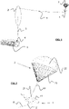
- the flying object 1 can comprise one or more rotor(s) 11 for its lift.
- the flying object 1 can also comprise an articulated rod 12 intended to be connected to the retaining cable 5.
- This articulated rod 12 makes it possible to move the retaining cable 5 away from the rotor(s) 11 in order to avoid that the retaining cable 5 becomes entangled in the (or in one of the) rotor(s) 11.
- the flying object 1 can also comprise a location system such as a GPS system (abbreviation of the Anglo-Saxon expression “ Global Positioning System” ) and wireless communication means to exchange data with the security system. It can also include various sensors - trim sensors, speed sensor, etc. - for the measurement of flight data enabling the safety system to detect a failure in its mode of operation.
- the uninhabited flying object 1 can for example be a drone piloted automatically (by a control unit) or from the ground by a user equipped with a remote control. Such a flying object 1 is well known to those skilled in the art and will not be described in more detail below.
- the flying object 1 can carry various pieces of equipment such as one (or more) on-board camera(s). It can for example be used to take shots in the context of television events, such as sporting events.
- the flying object 1 is likely to be used in populated areas (stadium, etc.). This is why the inventors have developed the security system described below in order to ensure the safety of the public and limit the risks of damage to the on-board equipment by the flying object 1 in the event of a failure.
- the safety system comprises a wing support 21 intended to be mounted on the flying object 1.
- the first (respectively the second) housing may comprise a cylindrical envelope including a bottom and a side wall.
- the wing support 21 may include means for ejecting the wing 2 in the event of failure.
- ejection means can for example be of the pyrotechnic type. This makes it possible to have powerful and reactive means of ejection.
- the ejection means may include a piston compressed by a spring held compressed by a blocking element intended to be disengaged from the spring (for example by destruction of the latter) by a pyrotechnic element (such as a pyrotechnic shear ) powered by a low power electrical signal.
- a pyrotechnic element such as a pyrotechnic shear
- the wing support 21 further comprises wireless communication means for the exchange of information between the control station 6 and the wing support 21, in particular to allow the reception of an activation signal from the means of ejection of the wing 2 in the event of detection of a failure.
- the wireless communication means can comprise an antenna of the radiofrequency type (WIFI, Bluetooth, etc.) for transmitting and/or receiving radio waves.
- the wing support 21 may also include mechanical triggering means to expel the reserve parachute in the event of damage to the ejection means of the wing 2.
- Wing 2 comprises at least one wing 22 and lines 23.
- the lines 23 are fine cords, the core of which may be made of polyethylene. They make it possible to connect the wing 22 to the wing support 21.
- the wing 22 is preferably made of a light and resistant material. It can be of the parasailing or paragliding type.
- the wing can be bi-surface and include boxes extending between an upper sail forming the upper surface and a lower sail forming the lower surface. The air is intended to rush into the cells of the wing at the level of its leading edge to give it its shape and allow it to generate sufficient lift to maintain the flying object at altitude.
- the wing can be monosurface, that is to say be devoid of a lower sail forming an intrados.
- the mast 3 can be of the telescopic type to facilitate its transport.
- Mast 3 may include linking means articulated at its base to allow mast 3 to pivot about an axis of rotation between a horizontal position and a vertical position. Mast 3 may also include adjacent telescoping sections slidable relative to each other between retracted and extended positions.
- the mast 3 can also comprise a motor and/or a jack to allow the displacement of the mast sections between said retracted and deployed positions.
- a motor and/or a jack can be associated with the articulated connection means to facilitate the pivoting of the mast 3 around its axis of rotation between the horizontal and vertical positions.
- the upper cylinders 312 are arranged on the lower cylinders 311 so that the axes of rotation of the upper cylinders 312 extend perpendicular to the axes of rotation of the lower cylinders 311.
- the mast can also include one (or more) inflatable cushion(s) into which air (or another gas) can be injected very quickly to inflate it and thus cushion a possible impact. between the flying object and the mast. This reduces the risk of damage to the flying object and/or the equipment it carries during the repatriation of the flying object 1.
- the airbag(s) can ( can) for example be mounted at the masthead.
- the reel 4 enables the retaining cable 5 of the security system to be wound or unwound.
- the winder 4 comprises a drum 41 rotatably mounted on a support base 42.
- the winder 4 also comprises a motor 43 connected to a shaft of the drum 41 to drive the drum 41 in rotation.
- the motor 43 (controlled by the control station 6) is capable of rotating the drum 41 in a single direction of rotation to allow the winding of the retaining cable 5, the motor 43 being decoupled from the drum 41 during the unwinding of the retaining cable 5.
- the motor 43 (controlled by the control station 6) is capable of rotating the drum 41 in both directions of rotation (antigonometric direction and retrograde direction). This makes it possible to maintain the tension of the restraint cable 5 within a specific tension range when unwinding the restraint cable 5.
- the reel 4 can comprise a sensor for measuring the length of unwound cable and/or a sensor for measuring the tension of the unwound cable.
- the reel may also include an emergency stop button allowing a user to deactivate the motor 43 in the event of a problem.
- the retaining cable 5 can be made up of fibers made of a resistant, non-extensible and light material, such as Kevlar ® or Dyneema ® .
- a resistant, non-extensible and light material such as Kevlar ® or Dyneema ® .
- the use of Dyneema ® has the advantage of making it possible to obtain a cable as resistant as a steel cable but ten times lighter.
- Kevlar ® or Dyneema ® cables have the advantage of being relatively inextensible.
- the weight of the retaining cable can be between 0.5 and 3 grams per meter, preferably between 1 and 1.5 grams per meter. This makes it possible to have a retaining cable whose weight has no effect on the flight conditions of the flying object.
- the retaining cable 5 is intended to be fixed to the drum 41 of the winder 4 by one of its ends, and to the flying object 1 by its other end.
- the reel 4 being positioned at the base of the mast 3, the retaining cable 5 extends between the base and the head of the mast along attachment means provided along the mast.
- a sheath can be provided around the retaining cable 5 between the reel and the mast head to limit the wear of the retaining cable 5 against the cable guide 31 and the attachment means provided along the mast 3 .
- the cable guide 31 can include sensors - such as one (or more) accelerometer(s) and one (or more) magnetometer(s) - to estimate the orientation of the retaining cable 5 with respect to a reference reference, and thus deduce the position of the flying object 1 (taking into account the length of unwound cable).
- sensors - such as one (or more) accelerometer(s) and one (or more) magnetometer(s) - to estimate the orientation of the retaining cable 5 with respect to a reference reference, and thus deduce the position of the flying object 1 (taking into account the length of unwound cable).
- the control station 6 can comprise a computer (for example a processor), input means (for example a keyboard, a touch screen, etc.), display means (for example a screen), and transmission/reception (including for example an antenna) to exchange data with the flying object 1, the winder 4, the wing support 21, the mast 3, etc.
- a computer for example a processor
- input means for example a keyboard, a touch screen, etc.
- display means for example a screen
- transmission/reception including for example an antenna
- the control station 6 is for example composed of one (or more) workstation(s), and/or of one (or more) computer(s) and/or of a mobile telephone, and/or of an electronic tablet (such as an IPAD ® ), a personal assistant (or " PDA ", acronym for the English expression " Personal Digital Assistant” ), and/or any other type of terminal known to the man of the trade.
- an electronic tablet such as an IPAD ®
- PDA personal assistant
- PDA acronym for the English expression " Personal Digital Assistant”
- the control station 6 preferably comprises wired and/or wireless communication means for exchanging measurement data and control signals with the various elements of the security system as well as with the flying object 1.
- the detection of a failure in the mode of operation of the flying object can be obtained by a remote operator.
- a safety procedure can be initiated either by the control station 6, or by the remote operator - for example by pressing a button of emergency.
- the initiation of the security procedure induces the repatriation of the flying object 1 by the control station 6. More precisely, the control station 6 is programmed to emit command signals to the various elements of the security system in order to bring back the flying object 1 in a repatriation zone Z (for example located at the top of the mast 3).
- the angular speed of rotation can be inversely proportional to the tension of the restraint cable (respectively proportional to the distance between the flying object and the repatriation zone).
- the fact of reducing the speed of rotation of the drum 41 when the tension of the retaining cable increases makes it possible to repatriate the flying object while maintaining its altitude substantially constant, this tension depending in particular on the winds contrary to the direction of repatriation which can be exerted on the flying object, etc.
- the control station 6 commands the activation of the wing support 21 in order to deploy the wing 2 (step 300).
- a signaling of the failure for information can be displayed on the display means of the control station 6 (step 250). This informs the user (driver or third party) that a failure has been detected.
- control station 6 commands the stopping of the motor(s) of the flying object 1 (step 400).
- control station 6 can take into account the wind speed or the altitude of the flying object in the calculation of the angular speed of rotation.
- the control station 6 can also take into account the weight of the flying object 1 in its calculation, etc.
- the calculated angular rotational speed is used to control the reel motor 43 so as to move the drum 41 at the calculated angular rotational speed (sub-step 502).
- the flying object 1 Due to the resultant between the lift of the wing 2 and the tension of the retaining cable 5, the flying object 1 is brought back to the repatriation zone Z at an altitude that is substantially stable with respect to the triggering altitude of the wing .
- control station 6 adapts the angular speed of rotation of the drum 41 throughout the repatriation procedure.
- the control station 6 commands the deactivation of the engine 43 coupled to the drum 41 so that the winding of the retaining cable 5 is interrupted (step 600). An operator can then recover the flying object. For this, the retaining cable is unwound from the drum at reduced speed so that the flying object suspended from the mast is brought back to the foot of the mast.
- a threshold value for example half the height of the mast
- the control station monitors and keeps the flying object safe within a predefined flight zone around the mast.
- the control station collects data measured by sensors located on the flying object and on the ground, on the other hand the control station controls the winder and the wing support.
- the control station is independent of the flying object. It allows the automatic safety of the flying object in order to prevent it from falling to the ground causing human or material damage.
- control station is based both on measured data transmitted by the flying object, and on data measured on the ground (i.e. by integrated sensors in the mast, the furler, etc.).
- control station comes from its capacity to receive a multitude of information (from the various sensors, etc.), to analyze it and to trigger the necessary corrective actions without human intervention.
- the calculations implemented in the control station are carried out in real time to guarantee a reaction time adapted to the situation.
Landscapes
- Engineering & Computer Science (AREA)
- Aviation & Aerospace Engineering (AREA)
- Remote Sensing (AREA)
- Mechanical Engineering (AREA)
- Burglar Alarm Systems (AREA)
- Operating, Guiding And Securing Of Roll- Type Closing Members (AREA)
- Toys (AREA)
Claims (15)
- Sicherheitssystem eines unbemannten Flugobjekts (1), das von einem Benutzer auf dem Boden gesteuert wird, wobei das Sicherheitssystem erlaubt, die Absturzrisiken des Flugobjekts (1) bei einer Fehlfunktion zu reduzieren, wobei das Sicherheitssystem umfasst:- einen Segelhalter (21), der bestimmt ist, an dem Flugobjekt (1) angebracht zu sein,- ein flexibles Segel (2) wie ein Fallschirm, der über dem Segelhalter (21) angeordnet ist,- eine Wickeleinrichtung (4), die in einer Rückführungszone (Z) des Flugobjekts (1) befestigt ist, wobei die Wickeleinrichtung (4) eine Wickeltrommel (41) und einen Elektromotor (43) zum Antreiben der Trommel (41) einschließt,- ein Haltekabel (5), das bestimmt ist, durch das eine seiner Enden mit dem Flugobjekt (1) verbunden zu sein und mit der Wickeltrommel (41) durch sein anderes Ende verbunden zu sein,- eine Überwachungsstation (6), um, wenn eine Fehlfunktion unter den Flugbedingungen des Flugobjekts (1) ermittelt wird:wobei das Sicherheitssystem Sensoren für das Sammeln des Abstands zwischen dem Flugobjekt und der Rückführungszone oder der Länge des abgewickelten Kabels und/oder der Spannung des Haltekabels einschließt, wobei die Sensoren ausgewählt sind aus:o die Aktivierung des Segelhalters (21) zu befehlen, um das flexible Segel (2) zu entfalten,o die Aktivierung des Elektromotors (43) zu befehlen, um die Trommel (41) derart rotatorisch anzutreiben, dass das Haltekabel (5) auf die Trommel (41) gewickelt wird,- Sensoren, die bestimmt sind, in das Flugobjekt für die Ermittlung einer Position des Flugobjekts integriert zu sein, und/oder- Sensoren, die in die Wickeleinrichtung für die Ermittlung einer aufgewickelten/abgewickelten Länge des Kabels und/oder einer Spannung des Kabels integriert sind,dadurch gekennzeichnet, dass die Überwachungsstation (6) programmiert ist, um die Rotationswinkelgeschwindigkeit des Elektromotors (43) während der Rückführung des Flugobjekts (1) zu ändern in Abhängigkeit von:- dem Abstand zwischen dem Flugobjekt und der Rückführungszone, oder- der Länge des abgewickelten Kabels, und/oder- der Spannung des Haltekabels,wobei die Änderung darin besteht, die Rotationswinkelgeschwindigkeit des Elektromotors (43) zu verringern:- wenn der Abstand zwischen dem Flugobjekt (1) und der Rückführungszone (Z) oder die abgewickelte Kabellänge kürzer als ein Grenzwert ist, und/oder- wenn die Spannung des Haltekabels (5) größer als eine Grenzwertspannung ist.
- Sicherheitssystem nach Anspruch 1, wobei die Überwachungsstation (6) programmiert ist, um:o eine Rotationswinkelgeschwindigkeit in Abhängigkeit von einer gemessenen Spannung des Haltekabels (5) zu berechnen (501),o die Aktivierung des Elektromotors (43) zu befehlen (502), um die Trommel (41) in der berechneten Rotationswinkelgeschwindigkeit rotatorisch anzutreiben,o die vorangehenden Schritte zu wiederholen, wenn der Abstand zwischen dem Flugobjekt (1) und der Rückführungszone (Z) größer als ein vorher festgelegter Sollwert ist.
- Sicherheitssystem nach Anspruch 1, wobei die Überwachungsstation (6) programmiert ist, um:o eine Rotationswinkelgeschwindigkeit in Abhängigkeit vom Abstand zwischen dem Flugobjekt (1) und der Rückführungszone (Z) zu berechnen (501), undo die Aktivierung des Elektromotors (43) zu befehlen (502), um die Trommel (41) in der berechneten Rotationswinkelgeschwindigkeit rotatorisch anzutreiben,o die vorhergehenden Schritte zu wiederholen, wenn der Abstand zwischen dem Flugobjekt (1) und der Rückführungszone (Z) größer als ein vorher festgelegter Sollwert ist.
- Sicherheitssystem nach einem der Ansprüche 1 bis 3, wobei die Überwachungsstation (6) einen Rechner umfasst, um:o eine Information zu erhalten (100, 503), die für die Position des Flugobjekts (1) repräsentativ ist und eine Information, die für die Spannung des Haltekabels repräsentativ ist,o einen Abstand zwischen dem Flugobjekt (1) und der Rückführungszone (Z) zu schätzen,o eine Rotationswinkelgeschwindigkeit in Abhängigkeit von dem geschätzten Abstand und/oder von der Information, die für die Spannung des Haltekabels repräsentativ ist, zu berechnen (501),o die vorhergehenden Schritte zu wiederholen, wenn der geschätzte Abstand größer als ein Sollwert ist.
- Sicherheitssystem nach Anspruch 4, wobei der Rechner ferner mindestens einen Parameter berücksichtigt, der ausgewählt ist aus:∘ der Windgeschwindigkeit,∘ dem Gewicht des Flugobjekts,∘ der Höhe des Flugobjekts,um eine Rotationswinkelgeschwindigkeit des Motors (43) zu berechnen.
- Sicherheitssystem nach einem der Ansprüche 4 oder 5, wobei die Information, die für die Position des Flugobjekts repräsentativ ist, umfasst:o eine gemessene Länge des abgewickelten Kabels,o einen ersten Winkel, gemessen zwischen dem Haltekabel und einer horizontalen Bezugsebene,o einen zweiten Winkel, gemessen zwischen dem Haltekabel und einer vertikalen Bezugsebene,wobei der Rechner imstande ist, die Position des Flugobjekts ausgehend von der gemessenen Länge und dem gemessenen ersten und zweiten Winkel zu schätzen.
- Sicherheitssystem nach einem der Ansprüche 1 bis 6, das ferner einen beispielsweise teleskopischen Mast (3) umfasst, wobei das Flugobjekt (1) bestimmt ist, durch das Haltekabel (5) am freien Ende des Masts (3) befestigt zu sein.
- Verfahren zur Steuerung eines Sicherheitssystems eines unbemannten Flugobjekts (1), das von einem Benutzer auf dem Boden gesteuert wird, wobei das Sicherheitssystem erlaubt, die Absturzrisiken des Flugobjekts (1) bei einer Fehlfunktion zu reduzieren, wobei das Sicherheitssystem umfasst:- einen Segelhalter (21), der an dem Flugobjekt (1) angebracht ist,- ein flexibles Segel (2) wie ein Fallschirm, der über dem Segelhalter (21) angeordnet ist,- eine Wickeleinrichtung (4), die in einer Rückführungszone (Z) des Flugobjekts (1) befestigt ist, wobei die Wickeleinrichtung (4) eine Wickeltrommel (41) und einen Elektromotor (43) zum Antreiben der Trommel (41) einschließt,- ein Haltekabel (5), das durch das eine seiner Enden mit dem Flugobjekt (1) verbunden ist und mit der Wickeltrommel (41) durch sein anderes Ende verbunden ist,wobei das Verfahren, wenn eine Fehlfunktion unter den Flugbedingungen des Flugobjekts ermittelt wird, die Schritte umfasst, die darin bestehen:o ausgehend von einer Überwachungsstation (6) die Aktivierung des Segelhalters (21) zu befehlen (300), um das flexible Segel zu entfalten,o ausgehend von der Überwachungsstation die Aktivierung des Elektromotors zu befehlen (500), um die Trommel derart rotatorisch anzutreiben, dass das Haltekabel auf die Trommel gewickelt wird,dadurch gekennzeichnet, dass der Schritt, der darin besteht, die Aktivierung des Elektromotors (43) zu befehlen (500), einen Unterschritt umfasst, der darin besteht, die Rotationswinkelgeschwindigkeit des Elektromotors (43) während der Rückführung des Flugobjekts (1) in Abhängigkeit vom Abstand zwischen dem Flugobjekt und der Rückführungszone oder von der Länge des abgewickelten Kabels und/oder von der Spannung des Haltekabels zu ändern, wobei die Änderung darin besteht, die Rotationswinkelgeschwindigkeit des Elektromotors (43) zu verringern:- wenn der Abstand zwischen dem Flugobjekt (1) und der Rückführungszone (Z) oder die Länge des abgewickelten Kabels (5) kürzer als ein Grenzwert ist, und/oder- wenn die Spannung des Haltekabels (5) größer als eine Grenzwertspannung ist.
- Verfahren nach Anspruch 8, wobei
der Schritt, der darin besteht, die Aktivierung des Elektromotors zu befehlen, die folgenden Unterschritte aufweist:- Berechnen einer Rotationswinkelgeschwindigkeit in Abhängigkeit von einer gemessenen Spannung des Kabels,- Aktivieren des Elektromotors in der berechneten Rotationswinkelgeschwindigkeit,- Wiederholen der beiden vorhergehenden Unterschritte, wenn der Abstand zwischen dem Flugobjekt und der Rückführungszone größer als ein vorher festgelegter Sollwert ist. - Verfahren nach Anspruch 9, wobei
der Unterschritte des Berechnens darin besteht, einen ersten Rotationswinkelgeschwindigkeitswert des Motors zuzuweisen, wenn die Spannung des Haltekabels größer als eine vorher festgelegte Grenzwertspannung ist und einen zweiten Rotationswinkelgeschwindigkeitswert zuzuweisen, der größer als der erste Wert ist, wenn die Spannung des Haltekabels kleiner als die vorher festgelegte Grenzwertspannung ist. - Verfahren nach Anspruch 8, wobei
der Schritt, der darin besteht, die Aktivierung des Elektromotors zu befehlen, die folgenden Unterschritte aufweist:- Berechnen einer Rotationswinkelgeschwindigkeit in Abhängigkeit vom Abstand zwischen dem Flugobjekt und der Rückführungszone, und- Aktivieren des Elektromotors in der berechneten Rotationswinkelgeschwindigkeit,- Wiederholen der beiden vorhergehenden Unterschritte, wenn der Abstand zwischen dem Flugobjekt und der Rückführungszone größer als ein vorher festgelegter Sollwert ist. - Verfahren nach Anspruch 11, wobei
der Unterschritte des Berechnens darin besteht, einen ersten Rotationswinkelgeschwindigkeitswert des Motors zuzuweisen, wenn der Abstand zwischen dem Flugobjekt und der Rückführungszone kleiner als ein vorher festgelegter Grenzwertabstand ist und einen zweiten Rotationswinkelgeschwindigkeitswert zuzuweisen, der größer als der erste Wert ist, wenn der Abstand zwischen dem Flugobjekt und der Rückführungszone größer als der vorher festgelegte Grenzwertabstand ist. - Verfahren nach Anspruch 8, wobei
der Schritt, der darin besteht, die Aktivierung des Elektromotors zu befehlen, die folgenden Unterschritte aufweist:o Erhalten einer Information, die für die Position des Flugobjekts repräsentativ ist und einer Information, die für die Spannung des Haltekabels repräsentativ ist,o Schätzen eines Abstands zwischen dem Flugobjekt und der Rückführungszone,o Berechnen einer Rotationswinkelgeschwindigkeit in Abhängigkeit von dem geschätzten Abstand und/oder von der Information, die für die Spannung des Haltekabels repräsentativ ist,o Wiederholen der vorhergehenden Schritte, wenn der geschätzte Abstand größer als ein vorher festgelegter Sollwert ist. - Verfahren nach Anspruch 13, wobei
der Unterschritt des Berechnens einer Winkelgeschwindigkeit ferner mindestens einen Parameter berücksichtigt, der ausgewählt ist aus:o der Windgeschwindigkeit,o dem Gewicht des Flugobjekts,o der Höhe des Flugobjekts,um eine Rotationswinkelgeschwindigkeit des Motors zu berechnen. - Verfahren nach einem der Ansprüche 13 oder 14, wobei die Information, die für die Position des Flugobjekts repräsentativ ist, umfasst:o eine gemessene Länge des abgewickelten Kabels,o einen ersten Winkel, gemessen zwischen dem Haltekabel und einer horizontalen Bezugsebene,o einen zweiten Winkel, gemessen zwischen dem Haltekabel und einer vertikalen Bezugsebene,wobei das Verfahren vor dem Unterschritt, der darin besteht, einen Abstand zwischen dem Flugobjekt und der Rückführungszone zu schätzen, einen Unterschritt umfasst, der darin besteht, die Position des Flugobjekts ausgehend von der gemessenen Länge und dem gemessenen ersten und zweiten Winkel zu schätzen.
Applications Claiming Priority (2)
| Application Number | Priority Date | Filing Date | Title |
|---|---|---|---|
| FR1757564A FR3069851B1 (fr) | 2017-08-07 | 2017-08-07 | Systeme de securite pour objet volant |
| PCT/EP2018/071033 WO2019030116A1 (fr) | 2017-08-07 | 2018-08-02 | Système de sécurité pour objet volant inhabité |
Publications (2)
| Publication Number | Publication Date |
|---|---|
| EP3665077A1 EP3665077A1 (de) | 2020-06-17 |
| EP3665077B1 true EP3665077B1 (de) | 2022-07-27 |
Family
ID=60020141
Family Applications (1)
| Application Number | Title | Priority Date | Filing Date |
|---|---|---|---|
| EP18758822.3A Active EP3665077B1 (de) | 2017-08-07 | 2018-08-02 | Sicherheitssystem für unbemanntes flugobjekt |
Country Status (3)
| Country | Link |
|---|---|
| EP (1) | EP3665077B1 (de) |
| FR (1) | FR3069851B1 (de) |
| WO (1) | WO2019030116A1 (de) |
Families Citing this family (1)
| Publication number | Priority date | Publication date | Assignee | Title |
|---|---|---|---|---|
| CN112046789B (zh) * | 2020-09-14 | 2022-07-26 | 中国科学院微小卫星创新研究院 | 一种太阳帆板驱动机构的控制方法 |
Family Cites Families (5)
| Publication number | Priority date | Publication date | Assignee | Title |
|---|---|---|---|---|
| WO2010092253A1 (fr) * | 2009-02-12 | 2010-08-19 | Geocean | Ameliorations aux aerodynes captifs |
| US9290269B2 (en) * | 2013-03-15 | 2016-03-22 | CyPhy Works, Inc. | Spooler for unmanned aerial vehicle system |
| WO2016115155A1 (en) * | 2015-01-12 | 2016-07-21 | Ryan Mark A | Tethered flight control system for small unmanned aircraft |
| WO2016182750A1 (en) | 2015-04-28 | 2016-11-17 | SkyFallX, LLC | Autonomous safety and recovery system for unmanned aerial vehicles |
| US10099782B2 (en) * | 2015-12-31 | 2018-10-16 | Tribune Broadcasting Company, Llc | Tethered unmanned aerial vehicle system |
-
2017
- 2017-08-07 FR FR1757564A patent/FR3069851B1/fr not_active Expired - Fee Related
-
2018
- 2018-08-02 WO PCT/EP2018/071033 patent/WO2019030116A1/fr not_active Ceased
- 2018-08-02 EP EP18758822.3A patent/EP3665077B1/de active Active
Also Published As
| Publication number | Publication date |
|---|---|
| EP3665077A1 (de) | 2020-06-17 |
| FR3069851A1 (fr) | 2019-02-08 |
| WO2019030116A1 (fr) | 2019-02-14 |
| FR3069851B1 (fr) | 2021-08-06 |
Similar Documents
| Publication | Publication Date | Title |
|---|---|---|
| EP3615425B1 (de) | System mit einer drohne, einem draht und einer andockstation zur ermöglichung des landens von drohnen in verschlechterten bedingungen | |
| EP4257495B1 (de) | Verdrehsicherungsvorrichtung und verfahren zum anheben, aufhängen und bewegen einer last | |
| EP3712059B1 (de) | Verfahren und vorrichtung zum verschieben des schwerpunktes eines luftfahrzeugs | |
| EP3210658B1 (de) | Drohne, die mit hochklappbaren drohnenhalterungen ausgestattet ist | |
| US9493250B2 (en) | Impact protection apparatus | |
| EP3310656B1 (de) | Sicheres drahtgebundenes system für eine drohne | |
| JP6835871B2 (ja) | 飛行制御方法、無人航空機、飛行システム、プログラム、及び記録媒体 | |
| EP3661867B1 (de) | Sicherheitssystem und hebevorrichtung mit einem solchen sicherheitssystem | |
| JP6945764B1 (ja) | 無人飛行体システム、制御装置及び制御方法 | |
| FR3048185A1 (fr) | Drone avec bras de liaison pliable. | |
| WO2016130711A1 (en) | Pod operating system for a vertical take-off and landing (vtol) unmanned aerial vehicle (uav) | |
| CA2741372C (fr) | Procede de decollage automatique d'un aeronef a voilure souple, voile, et aeronef | |
| EP0490722B1 (de) | Einrichtung zur Luft- und/oder Landferndetektierung, insbesondere zur Detektierung der Waldbrände | |
| FR3012423A1 (fr) | Dispositif pour securiser les drones civils en vol, coupant la propulsion et expulsant un parachute si le drone sort de son domaine de vol normal ou si le telepilote demande l'arret d'urgence du vol | |
| US12179902B2 (en) | Smart cargo bay door(s) for a UAV | |
| EP3665077B1 (de) | Sicherheitssystem für unbemanntes flugobjekt | |
| US20240017827A1 (en) | UAV with Open Cargo Bay and Method of Operation | |
| KR20220117952A (ko) | 심리스한 전원 공급을 위한 드론의 배터리 교체 지원 방법 및 이를 위한 장치 | |
| CA3020283C (fr) | Drone muni d'au moins un parachute | |
| WO2016059953A1 (ja) | 電力供給システム | |
| US12515797B2 (en) | Payload retrieval apparatus with extending member for use with a uav | |
| KR102691573B1 (ko) | 이동하는 운행체에서 운용이 가능한 유선 드론 시스템 | |
| CN113138603B (zh) | 系绳管理系统和方法 | |
| EP4351752B1 (de) | Vorrichtung zum transport durch motorisierte zugschraube und zugehörige transportanordnung und verfahren | |
| KR102917683B1 (ko) | 드론을 이용한 인명 구조 방법 및 시스템 |
Legal Events
| Date | Code | Title | Description |
|---|---|---|---|
| STAA | Information on the status of an ep patent application or granted ep patent |
Free format text: STATUS: UNKNOWN |
|
| STAA | Information on the status of an ep patent application or granted ep patent |
Free format text: STATUS: THE INTERNATIONAL PUBLICATION HAS BEEN MADE |
|
| PUAI | Public reference made under article 153(3) epc to a published international application that has entered the european phase |
Free format text: ORIGINAL CODE: 0009012 |
|
| STAA | Information on the status of an ep patent application or granted ep patent |
Free format text: STATUS: REQUEST FOR EXAMINATION WAS MADE |
|
| 17P | Request for examination filed |
Effective date: 20200228 |
|
| AK | Designated contracting states |
Kind code of ref document: A1 Designated state(s): AL AT BE BG CH CY CZ DE DK EE ES FI FR GB GR HR HU IE IS IT LI LT LU LV MC MK MT NL NO PL PT RO RS SE SI SK SM TR |
|
| AX | Request for extension of the european patent |
Extension state: BA ME |
|
| DAV | Request for validation of the european patent (deleted) | ||
| DAX | Request for extension of the european patent (deleted) | ||
| GRAP | Despatch of communication of intention to grant a patent |
Free format text: ORIGINAL CODE: EPIDOSNIGR1 |
|
| STAA | Information on the status of an ep patent application or granted ep patent |
Free format text: STATUS: GRANT OF PATENT IS INTENDED |
|
| INTG | Intention to grant announced |
Effective date: 20220217 |
|
| GRAS | Grant fee paid |
Free format text: ORIGINAL CODE: EPIDOSNIGR3 |
|
| GRAA | (expected) grant |
Free format text: ORIGINAL CODE: 0009210 |
|
| STAA | Information on the status of an ep patent application or granted ep patent |
Free format text: STATUS: THE PATENT HAS BEEN GRANTED |
|
| AK | Designated contracting states |
Kind code of ref document: B1 Designated state(s): AL AT BE BG CH CY CZ DE DK EE ES FI FR GB GR HR HU IE IS IT LI LT LU LV MC MK MT NL NO PL PT RO RS SE SI SK SM TR |
|
| REG | Reference to a national code |
Ref country code: CH Ref legal event code: EP |
|
| REG | Reference to a national code |
Ref country code: DE Ref legal event code: R096 Ref document number: 602018038483 Country of ref document: DE |
|
| REG | Reference to a national code |
Ref country code: AT Ref legal event code: REF Ref document number: 1506915 Country of ref document: AT Kind code of ref document: T Effective date: 20220815 |
|
| REG | Reference to a national code |
Ref country code: IE Ref legal event code: FG4D Free format text: LANGUAGE OF EP DOCUMENT: FRENCH |
|
| REG | Reference to a national code |
Ref country code: LT Ref legal event code: MG9D |
|
| REG | Reference to a national code |
Ref country code: NL Ref legal event code: MP Effective date: 20220727 |
|
| PG25 | Lapsed in a contracting state [announced via postgrant information from national office to epo] |
Ref country code: SE Free format text: LAPSE BECAUSE OF FAILURE TO SUBMIT A TRANSLATION OF THE DESCRIPTION OR TO PAY THE FEE WITHIN THE PRESCRIBED TIME-LIMIT Effective date: 20220727 Ref country code: RS Free format text: LAPSE BECAUSE OF FAILURE TO SUBMIT A TRANSLATION OF THE DESCRIPTION OR TO PAY THE FEE WITHIN THE PRESCRIBED TIME-LIMIT Effective date: 20220727 Ref country code: PT Free format text: LAPSE BECAUSE OF FAILURE TO SUBMIT A TRANSLATION OF THE DESCRIPTION OR TO PAY THE FEE WITHIN THE PRESCRIBED TIME-LIMIT Effective date: 20221128 Ref country code: NO Free format text: LAPSE BECAUSE OF FAILURE TO SUBMIT A TRANSLATION OF THE DESCRIPTION OR TO PAY THE FEE WITHIN THE PRESCRIBED TIME-LIMIT Effective date: 20221027 Ref country code: NL Free format text: LAPSE BECAUSE OF FAILURE TO SUBMIT A TRANSLATION OF THE DESCRIPTION OR TO PAY THE FEE WITHIN THE PRESCRIBED TIME-LIMIT Effective date: 20220727 Ref country code: LV Free format text: LAPSE BECAUSE OF FAILURE TO SUBMIT A TRANSLATION OF THE DESCRIPTION OR TO PAY THE FEE WITHIN THE PRESCRIBED TIME-LIMIT Effective date: 20220727 Ref country code: LT Free format text: LAPSE BECAUSE OF FAILURE TO SUBMIT A TRANSLATION OF THE DESCRIPTION OR TO PAY THE FEE WITHIN THE PRESCRIBED TIME-LIMIT Effective date: 20220727 Ref country code: FI Free format text: LAPSE BECAUSE OF FAILURE TO SUBMIT A TRANSLATION OF THE DESCRIPTION OR TO PAY THE FEE WITHIN THE PRESCRIBED TIME-LIMIT Effective date: 20220727 Ref country code: ES Free format text: LAPSE BECAUSE OF FAILURE TO SUBMIT A TRANSLATION OF THE DESCRIPTION OR TO PAY THE FEE WITHIN THE PRESCRIBED TIME-LIMIT Effective date: 20220727 |
|
| REG | Reference to a national code |
Ref country code: AT Ref legal event code: MK05 Ref document number: 1506915 Country of ref document: AT Kind code of ref document: T Effective date: 20220727 |
|
| PG25 | Lapsed in a contracting state [announced via postgrant information from national office to epo] |
Ref country code: PL Free format text: LAPSE BECAUSE OF FAILURE TO SUBMIT A TRANSLATION OF THE DESCRIPTION OR TO PAY THE FEE WITHIN THE PRESCRIBED TIME-LIMIT Effective date: 20220727 Ref country code: IS Free format text: LAPSE BECAUSE OF FAILURE TO SUBMIT A TRANSLATION OF THE DESCRIPTION OR TO PAY THE FEE WITHIN THE PRESCRIBED TIME-LIMIT Effective date: 20221127 Ref country code: HR Free format text: LAPSE BECAUSE OF FAILURE TO SUBMIT A TRANSLATION OF THE DESCRIPTION OR TO PAY THE FEE WITHIN THE PRESCRIBED TIME-LIMIT Effective date: 20220727 Ref country code: GR Free format text: LAPSE BECAUSE OF FAILURE TO SUBMIT A TRANSLATION OF THE DESCRIPTION OR TO PAY THE FEE WITHIN THE PRESCRIBED TIME-LIMIT Effective date: 20221028 |
|
| REG | Reference to a national code |
Ref country code: CH Ref legal event code: PL |
|
| PG25 | Lapsed in a contracting state [announced via postgrant information from national office to epo] |
Ref country code: SM Free format text: LAPSE BECAUSE OF FAILURE TO SUBMIT A TRANSLATION OF THE DESCRIPTION OR TO PAY THE FEE WITHIN THE PRESCRIBED TIME-LIMIT Effective date: 20220727 Ref country code: RO Free format text: LAPSE BECAUSE OF FAILURE TO SUBMIT A TRANSLATION OF THE DESCRIPTION OR TO PAY THE FEE WITHIN THE PRESCRIBED TIME-LIMIT Effective date: 20220727 Ref country code: MC Free format text: LAPSE BECAUSE OF FAILURE TO SUBMIT A TRANSLATION OF THE DESCRIPTION OR TO PAY THE FEE WITHIN THE PRESCRIBED TIME-LIMIT Effective date: 20220727 Ref country code: LU Free format text: LAPSE BECAUSE OF NON-PAYMENT OF DUE FEES Effective date: 20220802 Ref country code: LI Free format text: LAPSE BECAUSE OF NON-PAYMENT OF DUE FEES Effective date: 20220831 Ref country code: DK Free format text: LAPSE BECAUSE OF FAILURE TO SUBMIT A TRANSLATION OF THE DESCRIPTION OR TO PAY THE FEE WITHIN THE PRESCRIBED TIME-LIMIT Effective date: 20220727 Ref country code: CZ Free format text: LAPSE BECAUSE OF FAILURE TO SUBMIT A TRANSLATION OF THE DESCRIPTION OR TO PAY THE FEE WITHIN THE PRESCRIBED TIME-LIMIT Effective date: 20220727 Ref country code: CH Free format text: LAPSE BECAUSE OF NON-PAYMENT OF DUE FEES Effective date: 20220831 Ref country code: AT Free format text: LAPSE BECAUSE OF FAILURE TO SUBMIT A TRANSLATION OF THE DESCRIPTION OR TO PAY THE FEE WITHIN THE PRESCRIBED TIME-LIMIT Effective date: 20220727 |
|
| REG | Reference to a national code |
Ref country code: DE Ref legal event code: R097 Ref document number: 602018038483 Country of ref document: DE Ref country code: BE Ref legal event code: MM Effective date: 20220831 |
|
| PG25 | Lapsed in a contracting state [announced via postgrant information from national office to epo] |
Ref country code: SK Free format text: LAPSE BECAUSE OF FAILURE TO SUBMIT A TRANSLATION OF THE DESCRIPTION OR TO PAY THE FEE WITHIN THE PRESCRIBED TIME-LIMIT Effective date: 20220727 Ref country code: EE Free format text: LAPSE BECAUSE OF FAILURE TO SUBMIT A TRANSLATION OF THE DESCRIPTION OR TO PAY THE FEE WITHIN THE PRESCRIBED TIME-LIMIT Effective date: 20220727 |
|
| PLBE | No opposition filed within time limit |
Free format text: ORIGINAL CODE: 0009261 |
|
| STAA | Information on the status of an ep patent application or granted ep patent |
Free format text: STATUS: NO OPPOSITION FILED WITHIN TIME LIMIT |
|
| PG25 | Lapsed in a contracting state [announced via postgrant information from national office to epo] |
Ref country code: AL Free format text: LAPSE BECAUSE OF FAILURE TO SUBMIT A TRANSLATION OF THE DESCRIPTION OR TO PAY THE FEE WITHIN THE PRESCRIBED TIME-LIMIT Effective date: 20220727 |
|
| 26N | No opposition filed |
Effective date: 20230502 |
|
| PG25 | Lapsed in a contracting state [announced via postgrant information from national office to epo] |
Ref country code: IE Free format text: LAPSE BECAUSE OF NON-PAYMENT OF DUE FEES Effective date: 20220802 |
|
| PG25 | Lapsed in a contracting state [announced via postgrant information from national office to epo] |
Ref country code: SI Free format text: LAPSE BECAUSE OF FAILURE TO SUBMIT A TRANSLATION OF THE DESCRIPTION OR TO PAY THE FEE WITHIN THE PRESCRIBED TIME-LIMIT Effective date: 20220727 |
|
| PG25 | Lapsed in a contracting state [announced via postgrant information from national office to epo] |
Ref country code: BE Free format text: LAPSE BECAUSE OF NON-PAYMENT OF DUE FEES Effective date: 20220831 |
|
| PG25 | Lapsed in a contracting state [announced via postgrant information from national office to epo] |
Ref country code: MK Free format text: LAPSE BECAUSE OF FAILURE TO SUBMIT A TRANSLATION OF THE DESCRIPTION OR TO PAY THE FEE WITHIN THE PRESCRIBED TIME-LIMIT Effective date: 20220727 Ref country code: CY Free format text: LAPSE BECAUSE OF FAILURE TO SUBMIT A TRANSLATION OF THE DESCRIPTION OR TO PAY THE FEE WITHIN THE PRESCRIBED TIME-LIMIT Effective date: 20220727 |
|
| PG25 | Lapsed in a contracting state [announced via postgrant information from national office to epo] |
Ref country code: IT Free format text: LAPSE BECAUSE OF FAILURE TO SUBMIT A TRANSLATION OF THE DESCRIPTION OR TO PAY THE FEE WITHIN THE PRESCRIBED TIME-LIMIT Effective date: 20220727 Ref country code: HU Free format text: LAPSE BECAUSE OF FAILURE TO SUBMIT A TRANSLATION OF THE DESCRIPTION OR TO PAY THE FEE WITHIN THE PRESCRIBED TIME-LIMIT; INVALID AB INITIO Effective date: 20180802 |
|
| PG25 | Lapsed in a contracting state [announced via postgrant information from national office to epo] |
Ref country code: BG Free format text: LAPSE BECAUSE OF FAILURE TO SUBMIT A TRANSLATION OF THE DESCRIPTION OR TO PAY THE FEE WITHIN THE PRESCRIBED TIME-LIMIT Effective date: 20220727 |
|
| PG25 | Lapsed in a contracting state [announced via postgrant information from national office to epo] |
Ref country code: MT Free format text: LAPSE BECAUSE OF FAILURE TO SUBMIT A TRANSLATION OF THE DESCRIPTION OR TO PAY THE FEE WITHIN THE PRESCRIBED TIME-LIMIT Effective date: 20220727 |
|
| PGFP | Annual fee paid to national office [announced via postgrant information from national office to epo] |
Ref country code: DE Payment date: 20250820 Year of fee payment: 8 |
|
| PGFP | Annual fee paid to national office [announced via postgrant information from national office to epo] |
Ref country code: GB Payment date: 20250820 Year of fee payment: 8 |
|
| PGFP | Annual fee paid to national office [announced via postgrant information from national office to epo] |
Ref country code: FR Payment date: 20250828 Year of fee payment: 8 |
|
| PG25 | Lapsed in a contracting state [announced via postgrant information from national office to epo] |
Ref country code: TR Free format text: LAPSE BECAUSE OF FAILURE TO SUBMIT A TRANSLATION OF THE DESCRIPTION OR TO PAY THE FEE WITHIN THE PRESCRIBED TIME-LIMIT Effective date: 20220727 |
|
| REG | Reference to a national code |
Ref country code: GB Ref legal event code: 732E Free format text: REGISTERED BETWEEN 20251204 AND 20251210 |
|
| REG | Reference to a national code |
Ref country code: DE Ref legal event code: R081 Ref document number: 602018038483 Country of ref document: DE Owner name: HYPERION SEVEN, FR Free format text: FORMER OWNERS: CENTRE NATIONAL DE LA RECHERCHE SCIENTIFIQUE, PARIS, FR; ECOLE NORMALE SUPERIEURE DE LYON, LYON, FR; UNIVERSITE CLAUDE BERNARD LYON 1, VILLEURBANNE, FR |